EP2431685B1 - Air conditioner - Google Patents
Air conditioner Download PDFInfo
- Publication number
- EP2431685B1 EP2431685B1 EP10775079.6A EP10775079A EP2431685B1 EP 2431685 B1 EP2431685 B1 EP 2431685B1 EP 10775079 A EP10775079 A EP 10775079A EP 2431685 B1 EP2431685 B1 EP 2431685B1
- Authority
- EP
- European Patent Office
- Prior art keywords
- oil
- heat exchange
- refrigerant
- tube
- exchange units
- Prior art date
- Legal status (The legal status is an assumption and is not a legal conclusion. Google has not performed a legal analysis and makes no representation as to the accuracy of the status listed.)
- Active
Links
Images


Classifications
-
- F—MECHANICAL ENGINEERING; LIGHTING; HEATING; WEAPONS; BLASTING
- F25—REFRIGERATION OR COOLING; COMBINED HEATING AND REFRIGERATION SYSTEMS; HEAT PUMP SYSTEMS; MANUFACTURE OR STORAGE OF ICE; LIQUEFACTION SOLIDIFICATION OF GASES
- F25B—REFRIGERATION MACHINES, PLANTS OR SYSTEMS; COMBINED HEATING AND REFRIGERATION SYSTEMS; HEAT PUMP SYSTEMS
- F25B31/00—Compressor arrangements
- F25B31/002—Lubrication
- F25B31/004—Lubrication oil recirculating arrangements
-
- F—MECHANICAL ENGINEERING; LIGHTING; HEATING; WEAPONS; BLASTING
- F04—POSITIVE - DISPLACEMENT MACHINES FOR LIQUIDS; PUMPS FOR LIQUIDS OR ELASTIC FLUIDS
- F04B—POSITIVE-DISPLACEMENT MACHINES FOR LIQUIDS; PUMPS
- F04B39/00—Component parts, details, or accessories, of pumps or pumping systems specially adapted for elastic fluids, not otherwise provided for in, or of interest apart from, groups F04B25/00 - F04B37/00
- F04B39/02—Lubrication
Definitions
- the present invention relates to an air conditioner, more particularly, to an air conditioner that refrigerant and the oil mixed the refrigerant is superheated or supercooled by using the heat discharged from a condenser while the oil returned from an evaporator or a compressor flows into the compressor again and is reused. Therefore, it is possible to increase the durability and the compression performance of the compressor.
- an air conditioner comprises a compressor, a condenser, an expansion device and an evaporator.
- the air conditioner cools or heats an indoor space by using a refrigeration cycle including a phase change and a pressure change of the refrigerant while a refrigerant circulates the compressor, the condenser, the expansion device and the evaporator.
- the compressor When the compressor is operated, a mechanical friction is necessarily caused.
- oil is used in lubrication to protect the compressor from the mechanical friction.
- the refrigerant becomes high temperature/high pressure refrigerant by compression of the compressor, the oil discharged from the compressor with the refrigerant reaches high temperature.
- an oil cooler may be disposed to cool the oil collected to the compressor.
- the conventional air conditioner has to comprise a separate oil cooler for cooling an oil collected to the compressor, so that it needs a separate cooling device such as fan for cooling the oil cooler.
- the refrigerant mixed with the oil flows in the evaporator, the oil inside of the evaporator adhere to the heat exchange pipe disposed in the evaporator so that heat exchange performance is decreased.
- it may further comprise an oil recovery device to collect oil from the evaporator.
- the oil returned by the oil recovery device may be mixed with the refrigerant as well as oil, the refrigerant mixed with the oil is liquid state vaporized by the evaporator. If the refrigerant directly flows into the compressor, the compressor compressed the refrigerant in liquid state so that the performance of the compressor is decreased or the durability of the compressor is remarkably decreased.
- WO 2006/126396 A1 relates to a refrigeration cycle device that has a refrigerant circuit where a compressor, a radiator, an expander, an oil separator, and an evaporator are connected in this order, and also has an oil feeding pipe for connecting the oil separator and piping on the entrance side of the compressor.
- the oil feeding pipe In the oil feeding pipe are arranged a valve whose degree of opening is controllable and a heater for heating lubrication oil by heat exchange between a high-pressure refrigerant and the lubrication oil.
- DD 133 063 A1 relates to a cold-steam compression refrigerating system working with an oil-soluble refrigerant, whose evaporator is flooded with refrigerant, from which, for oil recirculation, a partial stream of liquid refrigerant-oil mixture is continually withdrawn, evaporated and passed into the suction pipe of the compressor.
- An object of the present invention is to provide an air conditioner, which comprises an oil recovery flow path connecting an evaporator with a compressor for superheating refrigerant mixed with oil returned from an evaporator by using a condenser or an oil recovery flow path connecting an oil separator to a compressor for supercooling oil collected from an oil separator by using a condenser.
- the air conditioner according to the present invention comprises a compressor which compresses refrigerant; and a condenser which comprises a heat-exchange unit having a refrigerant tube for passing refrigerant and a plurality of radiating fins disposed around the refrigerant tube, and condenses refrigerant compressed in the compressor by heat-exchanging with air passing through the heat-exchange unit; and an expansion device for expanding refrigerant condensed by the condenser; and an evaporator for evaporating refrigerant expanded by the expansion device, and an oil recovery flow path which collects oil from the evaporator into the compressor, and passes through the condenser for heating the oil and the refrigerant mixed with the oil by passing the heat-exchange unit of the condenser before oil is returned to the compressor.
- an oil tube may be disposed in the heat-exchange unit to form a portion of the oil recovery flow path.
- the heat-exchange units make a pair that a gap between each of lower sides is smaller than a gap between each of the upper sides, and the oil tube may be formed at the lower side of any one of the heat-exchange units in a body.
- the heat-exchange units make a pair that a gap between each of the lower sides is smaller than a gap between each of the upper sides.
- Several pairs of the heat-exchange units form a plurality of columns and are disposed at regular intervals, and the oil tube may be formed at the lower side of any one of the heat-exchange units in a body.
- the heat-exchange units make a pair that a gap between each of the lower sides is smaller than a gap between each of the upper sides.
- Several pairs of the heat-exchange unit form a plurality of columns and are disposed at regular intervals, and the oil tube may be formed at each lower side of the heat-exchange units in a body.
- it may further comprise a fan for blowing air to pass the heat-exchange unit.
- the heat-exchange unit comprises a plurality of pipe columns, which are parallel to a surface of the heat-exchange unit in which the air flows by the fan, some of a plurality of pipe columns may be the refrigerant tube and the oil tube, and the rest of a plurality of pipe columns may be the refrigerant tube.
- oil tube in the pipe columns having the refrigerant tube and the oil tube may be disposed at the last column close to the other surface of the heat-exchange unit, which air flows out.
- the heat-exchange unit makes a pair that a gap between each of the lower sides is smaller than a gap between each of the upper sides.
- the heat-exchange unit may further comprise an oil tube which forms a portion of the oil recovery flow path and an oil cooler disposed a space between a plurality heat-exchange units and a fan which blows air to pass the heat-exchange part.
- the fan may be disposed at an upper side of the oil cooler.
- the oil cooler and any one of the opposite face of the heat exchange units are parallel to each other.
- the oil cooler is contact with the radiating fin.
- the oil cooler is disposed to be horizontal at a space between the heat exchange units.
- the air conditioner of the present invention returns the oil from shell and tube type of evaporator and directs the returned oil into the compressor.
- the oil and the refrigerant mixed with the oil is heated by using the heat discharged from the heat exchange units, so that it is possible to improve a compression performance and a heat exchange performance of the evaporator.
- the oil that the quantity for heat-exchanging is less than that of the refrigerant is cooled by using a part of the condenser, so that it has an advantage that the extra oil cooler is not needed for cooling the oil.
- the oil cooler is disposed at a space between a plurality of heat exchange units, so that it can make better use of a space of the air conditioner and can blow the air passing the oil cooler by using the fan passing the condenser.
- the air conditioner of the present invention cools the oil by using a partial pipe column of the plurality of pipe columns of the heat exchange units, so that it cannot prevent to condense the refrigerant passing the other pipe columns.
- FIG. 1 shows a refrigeration cycle of an air conditioner according to the present invention.
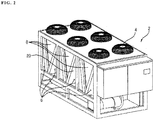
- FIG. 2 is a perspective view showing the exterior of the air conditioner according to the present invention.
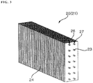
- FIG. 3 is a perspective view showing a heat exchange unit of a condenser according to an exemplary embodiment of the present invention.
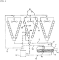
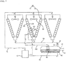
- FIG. 4 to FIG. 8 shows a flow path of the refrigerant and oil according to a variety of exemplary embodiment of the present invention.
- an air conditioner according to the exemplary embodiment of the present invention comprises a compressor 10 for compressing refrigerant, a condenser 20 for condensing refrigerant compressed by the compressor 10, an expansion device 30 for expanding refrigerant condensed by the condenser 20, an evaporator 40 for evaporating refrigerant expanded by the expansion device 30.
- the compressor 10 compresses refrigerant into high temperature/high pressure gas-phase refrigerant (referred to as 'gas refrigerant' hereinafter).
- a first connection pipe 15 connects the compressor 10 and the condenser 20 so that gas refrigerant can flow through the first connection pipe 15..
- the condenser 20 condenses the high temperature/high pressure refrigerant transferred from the compressor 10 through the first connection pipe 15 and changes phase of the refrigerant to medium temperature/high pressure liquid refrigerant(referred as 'liquid refrigerant' hereinafter) and discharges heat generated by phase change of the refrigerant to the outside.
- the condenser 20 is a kind of heat exchanger, referring to FIG. 3 , and comprises a refrigerant tube 23 which the gas refrigerant transferred from the compressor 10 circulates, a plurality of radiating fins 24 which is shaped to cover the outside of the refrigerant tube 23.
- the refrigerant tube 23 is a winding shape.
- the refrigerant tube 23 and the radiating fin 24 are to discharge heat of the gas refrigerant transferred from the refrigerant tube 23 to the outside air. It is desirable that the refrigerant tube 23 is made from high performance heat transfer material.
- the heat exchange unit 21 comprising the refrigerant tube 23 and the radiating fin 24 is disposed in the condenser case (not shown), and the air flows into the condenser 20 by the fan 50, and the air heat-exchanges with the gas refrigerant or the liquid refrigerant.
- a heat exchanger provided by the above-mentioned type is called as "a fin and tube type heat exchanger".
- the heat exchange unit 21 is provided that a plurality of the refrigerant tubes 23 are lined up in several columns (refer to 26, 27 in FIG.2 ). Each end of the refrigerant tubes 23 is connected so that the gas refrigerant or liquid refrigerant can flow to one way.
- columns of the refrigerant tubes 23 disposed in series about the direction of airflow are called as "a plurality of pipe columns 26 and 27".
- the heat exchange units 21 may be provided to make a pair 21 and 22 at the inside of the condenser case.
- Each pair of heat exchange units 21 and 22 may be disposed in the condenser case.
- Each pair of heat exchange units 21 and 22 are connected by a refrigerant connection pipe (not shown) so that the refrigerant may flow to the expansion device 30 through a second connection pipe 25 connecting the refrigerant connection pipe and the expansion device 30.
- the expansion device 30 reduces the pressure of the medium temperature/high pressure liquid refrigerant condensed by the condenser 20 and passed through the second connection pipe 25, so that the liquid refrigerant can easily change a phase in the following evaporator 40.
- a third connection pipe 35 connects the expansion device 30 and the evaporator 40. If the liquid refrigerant expected to evaporate in the evaporator 40 is at a low temperature state before flowing into the evaporator 40, cooling performance of the refrigerant is considerably improved. Thus, even though it is not shown in FIG, the refrigerant can be supercooled by the super-cooling heat exchanger before flowing into the expansion device 30.
- the liquid refrigerant expanded by the expansion device 30 flows into the evaporator 40 through the third connection pipe 35.
- the refrigerant flowing into the evaporator 40 takes heat from the surroundings and can cool a room, while the refrigerant evaporates in the evaporator 40 and changes to gas refrigerant.
- the evaporator 40 is a kind of heat exchanger like the condenser 20.
- the evaporator 40 may be a fin and tube type heat exchanger like the condenser 20.
- the evaporator 40 may not be a fin and tube type heat exchanger.
- the evaporator may comprise a case filled with refrigerant and a water pipe (not shown) which introduces a medium such as water to heat-exchange with the refrigerant.
- the water pipe connects with a water supply pipe 41 for supplying cold/hot water to a heat exchanger of an air-handling unit (AHU, not shown) and a water discharge pipe 42 for collecting the heat exchanged cold/hot water.
- AHU air-handling unit
- the kind of the heat exchanger is called "a shell and tube type heat exchanger" in distinction from the fin and tube type heat exchanger. Namely, in an air conditioner according to an exemplary embodiment of the present invention, it will hereinafter be described that the condenser is a fin and tube type heat exchanger and the evaporator is a shell and tube type heat exchanger.
- the compressor 10, the condenser 20, the expansion device 30 and the evaporator 40 are disposed in a main body 2 of the air conditioner, so that they construct a refrigeration cycle and performs heat absorption and heat emission.
- the evaporator 40 which heat-exchanges refrigerant with heating medium (air in the condenser 20 or water in the evaporator 40), is disposed in the main body 20, so that the refrigerant circulating the refrigeration cycle heat-exchanges with the heating medium and the heating medium heat exchanged is supplied to where heat is needed (for example, a space for cooling or heating).
- the evaporator 40 is disposed at the space which cooling or heating is needed and may cool or heat the space directly.
- the main body 2 is divided an upper space and a lower space.
- the condenser 20 and the fan 50 are disposed at the upper space.
- the evaporator 40 and the compressor 10 are disposed at the lower space.
- a pair of heat exchange unit 21 and 22 may be disposed across from each other at regular intervals.
- a space in which air passing through each the heat exchange unit 21 and 22 stays is formed between each of heat exchange units 21 and 22.
- the side of the space is separated from the outside by a side plate 8.
- the one pair of heat exchange unit 21 and 22 is disposed to have a gap between each of the upper sides larger than a gap between each of the lower sides and to have V-shaped cross section.
- a side air inlet 6 is formed in triangular shape in the side of the main body 2 so that air flows into the main body 2 through the side of the main body 2.
- a bottom air inlet is formed at a boundary surface between the upper space of the main body 2 at which the condenser 20 is disposed and the lower space of the main body 2 at which the compressor 10 and the evaporator 40.
- air flows into the main body 2 through the side air inlet 6 and the bottom air inlet and passes through the heat exchange unit 21 and 22, which make up the condenser 20.
- An air outlet 4 may be formed at the top surface of the main body 2 to correspond to the number of heat exchange pairs. The heat exchanged air passing through the condenser 20 flows to the outside through the air outlet 4 of the main body 2.
- the fan 5 is disposed at the space among the one pair of heat exchange unit 21 and 22 of the condenser 20 and the side plate 8 and the air outlet 4.
- the air directed into the main body 2 through the side air inlet 6 and the bottom air inlet discharges to the outside through the air outlet 4 after passing the one pair of the heat exchange unit 21 and 22 by the force of the fan 50.
- the air flows into an inflow surface of the heat exchange unit 21 and 22 and discharges through an outflow surface of the heat exchange unit 21 and 22.
- the refrigerant tube 23 that forms the one pair of the heat exchange unit 21 and 22 is disposed in series about the direction of airflow.
- An oil recovery means 60 may be constructed in the evaporator 40 to return the oil mixed with refrigerant from the compressor 10.
- the oil recovery means 60 has to construct in the evaporator 40.
- a state of the oil returned by the oil recovery means 60 is similar to a state of the refrigerant. Namely, it is obvious that the returned oil is low temperature/low pressure oil like the refrigerant inside of the evaporator 40.
- the oil returned by the oil recovery means 60 immediately flows into the compressor 10 again through an oil recovery flow path 100, so that it can solve problems of inconvenience that a user fills with oil to preserve the compressor 10.
- the oil recovery means 60 may return not only pure oil but also refrigerant by technical limits. If the low temperature/low pressure refrigerant returned by the oil recovery means 60 flows into the compressor 10, it is possible that a wet compression is occurred while the operation of the compressor 10 because of the nature of incompressible fluid. If the wet compression is occurred, the operating parts of the compressor may have problems easily.
- the compressor 10 compresses a gas refrigerant to the high temperature/high pressure gas refrigerant and circulates the refrigerant to the refrigeration cycle.
- An oil separator is provided on an outlet of the compressor 10 to separate the oil for use on a fabrication of the operation parts of the compressor 10 and to return the separated oil to the compressor 10.
- the oil separated by the oil separator 70 is cooled by an extra device called oil cooler, so that it prevents that a performance of the compressor 10 is decreased by the excessive temperature rise of the inside of the compressor 10.
- the oil recovery flow path 100 and 200 is formed as a flow path which can return the oil from the evaporator 40 and introduce the returned oil into the compressor 10 again, and passes through the condenser 20 so as to heat the oil and the refrigerant mixed with the oil by passing the heat exchange units 21 and 22 of the condenser 20.
- the oil recovery flow path 100 and 200 can prevent the wet compression of the compressor 10 and cool the oil and refrigerant separated by the oil separator 70 without the oil cooler.
- the oil flow path 100 for preventing the wet compression of the compressor 10 is formed to introduce the oil returned from the evaporator 40 into the compressor 10, but is formed to pass the condenser 20 before introducing to the compressor 10 so as to heat the oil and the refrigerant mixed with the oil by the heat discharged from the heat exchange units 21 and 22 of the condenser 20.
- the refrigerant mixed with the oil can be heated. It changes the phase of the refrigerant from liquid to gas, it has an effect that the wet compression of the refrigerant is prevented in the compressor 10.
- an oil tube 101 which forms a part of the oil return flow path 100 besides the refrigerant tube 23, may be disposed in the heat exchange units 21 and 22 in the heat exchange units 21 and 22 of the condenser 20.
- the oil return flow path 100 comprises a flow path connecting from the evaporator 40 to the compressor 10 and the oil tube 101 disposed in the condenser 20.
- the oil tube 101 is constructed at the heat exchange units 21 and 22 separately or in a body so as to heat the oil and the refrigerant mixed with the oil passing the inside of the condenser 20 by using the heat discharged from the condenser.
- the oil tube 101 is constructed at the heat exchange units 21 and 22 in a body, the oil tube 101 is suitable to its name and corresponds with the refrigerant tube 23 as specified. However, if the oil tube 101 is separated from the heat exchange units 21 and 22, it may use the name as oil cooler 102 comprising the oil tube 101 for convenience.
- the main composition related to the name as the oil cooler 102 is one of the various exemplary embodiments of the present invention.
- the oil tube 101 may be formed at the heat exchange units 21 and 22 in a body so as to constitute the lower side of any heat exchange unit (referred to as '21' of FIG. 4 ) among the one pair of heat exchange units 21 and 22.
- the oil tube 101 is formed at the heat exchange units 21 and 22 in a body to constitute the lower side of any heat exchange unit 21 among the one pair of heat exchange units 21 and 22 disposed in a V shape. Therefore, it is possible to heat the oil and the refrigerant passing the oil tube 101 by using the heat discharged from the heat-exchange unit 21.
- the air conditioner is also able to convert into a function, which supercools the oil and the refrigerant separated by the oil separator 70.
- the composition for preventing wet compression of the compressor 10 is a concept that it is able to heat because the temperature of the oil and the refrigerant mixed with the oil returned through the oil recovery flow path 100 is relatively lower than the temperature of the one pair of heat exchange units 21 and 22. On the contrary, it is possible to supercool by using the one pair of heat exchange units 21 and 22 whose temperature is relatively lower than the temperature of the refrigerant mixed with oil and the oil separated by the oil separator 70.
- any one of the one pair of heat exchange units 21 and 22 comprises the refrigerant tube 23, which refrigerant flows in, and the oil tube 101, which oil flows in.
- One side of the refrigerant tube 23 is connected to the first connection pipe 15 connecting with the compressor 10.
- the other side of the refrigerant tube 23 is connected to the second connection pipe 25 connecting with the expansion device 30 and circulates the refrigerant.
- One side of the oil tube 101 is connected with the oil recovery flow path 200 connecting to the oil separator 70.
- the other side of the oil tube 101 is connected with the oil recovery flow path 200 connecting to the compressor 10 and circulates the supercooled oil and the refrigerant mixed with oil.
- the heat exchange units 21 and 22 including the oil tube 101 oil cooling area
- the oil cooling area is disposed at the lower side of the heat exchange units 21 and 22.
- the exemplary embodiment of the present invention is not limited by the first exemplary embodiment.
- partial pipe column 27 of the plurality of pipe columns 26 and 27 in the heat exchange unit 21 is used for the oil tube 101 to form the oil recovery flow path 100 and 200.
- the rest of pipe column 26 of the plurality of pipe columns 26 and 27 is used for the refrigerant tube 23 to introduce the refrigerant flowing the normal refrigeration cycle regardless of the oil recovery flow path 100 and 200.
- the oil tube 101 according to the second exemplary embodiment is formed at the heat exchange unit 21 in a body like the first exemplary embodiment. But, the oil tube 101 according to the first exemplary embodiment is formed at the heat exchange unit 21 in a body so as to constitute the lower side of the heat exchange unit 21, the oil tube 101 according to the second exemplary embodiment is formed to constitute only one part of the lower side of the heat exchange unit 21, namely a part 27 of the plurality of the pipe columns 26 and 27. In other words, the first exemplary embodiment and the second exemplary embodiment differ in the position of the oil tube 101.
- the oil cooling area is near to the other side of the heat exchange units 21 and 22, which discharges the air flowing by the fan.
- the oil tube 101 is disposed at the last columns 27 among the plurality of the pipe columns 26 and 27 in the direction of the flow of air flowing by the fan 50.
- the air conditioner according to the second exemplary embodiment comprises that the air heat exchanged with the refrigerant tube 23 heat-exchanges with the oil passing through the oil tube 101.
- the air heat exchange with the oil passing through the oil tube 101 does not heat exchange with the refrigerant tube 23, so that it cannot affect the condensation of the refrigerant.
- the oil tube 101 is the lower side of the heat exchange units 21 and 22, like the first exemplary embodiment. It has an advantage of minimizing flow range of the oil and the oil mixed with refrigerant by decreasing the distance between the oil tube 101 and the compressor 10 or the oil separator disposed at the lower space of the main body 2 or the oil tube 101 and the oil separator 70 disposed at the lower space of the main body 2.
- the position of the oil tube 101 is set to be different with the first exemplary embodiment so that it is able to obtain more the heat exchange area about the oil tube 21 and has an advantage of increasing the heat exchange performance.
- the exemplary embodiment of the present invention is not limited at the first exemplary embodiment and the second exemplary embodiment.
- the heat-exchange units 21 and 22 makes a pair to have the gap between the lower sides is smaller than the distance between the upper sides.
- Several pairs of the heat exchange units form a plurality of columns and are disposed at regular intervals, and the oil tube 101 is formed at the lower side of any one of the heat exchange units 21 and 22 in a body.
- Such an exemplary embodiment is called as a third exemplary embodiment of the air conditioner.
- the oil tube 101 is not formed at the lower side of only one of the one pair of heat exchange units 21 and 22 like the first and second exemplary embodiment. However, the oil tube 101 is formed at each lower side of the one pair of heat exchange units 21 and 22 in a body so that the number of the oil tubes 101 is proportional to the number of the heat exchange units 21 and 22.
- the air conditioner according to the third exemplary embodiment has an advantage of resolving the heat exchange unbalance of the refrigerant between the heat exchange units 21 and 22 when the oil tube 101 is disposed at the any one of the heat exchange units 21 and 22.
- the air conditioner according to the present invention is realized by a fourth exemplary embodiment as follows.
- the oil cooling area at which the oil tube 101 is disposed is formed in the heat-exchange units 21 and 22 in a body.
- the oil cooling area may be disposed to contact with the heat exchange unit 21 regardless of the construction of the heat exchange units 21 and 22.
- the oil tube 101 is not a part of the heat exchange units 21 and 22, an extra component such as oil cooler 102 comprising the oil tube 101 may be disposed to contact with the radiating fins 24 among the components of the heat exchange units 21 and 22.
- the fan 50 is disposed at the upper side of the one pair of heat exchange units 21 and 22 and the air flows to the upper side by the fan 50, it is desirable that the oil cooler 102 is disposed at the one heat exchange unit 21 of the one pair of heat exchange units 21 and 22 and is diposed at the lower side of the opposite faces that the one pair of heat exchange units 21 and 22 faced each other.
- the oil cooler 102 is disposed to parallel to the opposite side of heat exchange units 21 and 22 faced each other. Namely, the oil cooler 102 is disposed close to the other side of the heat exchange units 21 and 22, which air flows out among the pipe columns 26 and 29 of the heat-exchange units 21 and 22 comprising the refrigerant tube 23.
- the heat exchange can be maximized.
- the air conditioner according to the present invention is realized by a fifth exemplary embodiment as follows.
- the oil cooler 102 is disposed a space between the one pair of heat-exchange units 21 and 22 not to contact the heat exchange units 21 and 22 so that the heat exchange can be properly performed between the one pair of heat-exchange units 21 and 22 and the oil tube 101 in the condenser 20
- the heat exchange rate is small because the heat exchange units 21 and 22 and the oil tube 101 is not directly contacted, but it is useful if the need for supercool of the refrigerant and the oil passing the oil tube 101 is a little.
- the air conditioner according to the fifth exemplary embodiment can reduce the flow resistance because it is not prevent the flow of the air.
- the extra fan is not needed for cooling the oil cooler 102.
- it can make better use of a space of the main body 2.
- the present invention has been particularly shown and described with reference to exemplary embodiments thereof.
- description about the super cool of the oil and the refrigerant mixed with the oil related from the oil recovery flow path 200 to the oil separator 70 is skipped, it will be included in the scope of the present invention as the same elements.
- the exemplary embodiments of the present invention describes that the number of the pipe columns 26 and 27 is two in the heat exchange units 21 and 22, it may be possible that the number of that is three.
- Two pipe columns of three pipe columns may comprise the refrigerant tube 23, and the third three pipe column may comprise the oil tube 101.
- the refrigerant compressed by the compressor 10 flows into the condenser in a gas-phase, the refrigerant directed into the condenser 20 is condensed by discharging the heat to the surrounding and by changing a phase.
- the refrigerant condensed by the condenser 20 is expanded by passing the supercooling heat exchanger or the expansion device 30, flows into the evaporator 40 and evaporates by absorbing the heat from the surrounding during the change of phase.
- the oil and the refrigerant mixed with the oil returned by the oil recovery means 60 disposed at the evaporator 40 flows into the oil cooler 102 or the condenser 20 at which the oil tube 101 is disposed and is fully heated by the heat discharged from the condenser 20 and then flows into the compressor 10 again.
- the low temperature/low pressure oil and refrigerant returned from the evaporator 40 is heated and then flows into the compressor again and can be reused. Therefore, it can prevent a wet compression of the compressor 10 and increase a heat exchange performance of products.
Applications Claiming Priority (3)
| Application Number | Priority Date | Filing Date | Title |
|---|---|---|---|
| KR1020090040917A KR20100121962A (ko) | 2009-05-11 | 2009-05-11 | 공기조화기 |
| KR1020090061811A KR101542120B1 (ko) | 2009-07-07 | 2009-07-07 | 칠러형 공기조화기 |
| PCT/KR2010/002944 WO2010131877A2 (ko) | 2009-05-11 | 2010-05-10 | 공기조화기 |
Publications (3)
| Publication Number | Publication Date |
|---|---|
| EP2431685A2 EP2431685A2 (en) | 2012-03-21 |
| EP2431685A4 EP2431685A4 (en) | 2014-06-25 |
| EP2431685B1 true EP2431685B1 (en) | 2019-07-03 |
Family
ID=43085435
Family Applications (1)
| Application Number | Title | Priority Date | Filing Date |
|---|---|---|---|
| EP10775079.6A Active EP2431685B1 (en) | 2009-05-11 | 2010-05-10 | Air conditioner |
Country Status (4)
| Country | Link |
|---|---|
| US (1) | US20120137723A1 (zh) |
| EP (1) | EP2431685B1 (zh) |
| CN (1) | CN102460040B (zh) |
| WO (1) | WO2010131877A2 (zh) |
Families Citing this family (3)
| Publication number | Priority date | Publication date | Assignee | Title |
|---|---|---|---|---|
| JP6742721B2 (ja) * | 2015-12-24 | 2020-08-19 | 株式会社前川製作所 | クーラユニット |
| CN106288524B (zh) * | 2016-08-16 | 2019-01-04 | 东北电力大学 | 带太阳能集热功能的翅片管结构 |
| CN106247690B (zh) * | 2016-08-16 | 2019-04-05 | 东北电力大学 | 翅片管式换热器 |
Family Cites Families (13)
| Publication number | Priority date | Publication date | Assignee | Title |
|---|---|---|---|---|
| US2954680A (en) * | 1957-03-28 | 1960-10-04 | V C Patterson & Associates Inc | Automatic defrosting apparatus |
| DD131963A1 (de) * | 1977-06-29 | 1978-08-09 | Eberhard Beyer | Verfahren zur oelrueckfuehrung in kaelteanlagen |
| DD133063A1 (de) * | 1977-09-13 | 1978-11-29 | Achim Franke | Einrichtung zur oelrueckfuehrung aus einem ueberflutet arbeitenden verdampfer |
| JPS56501659A (zh) * | 1979-12-03 | 1981-11-12 | ||
| US5761914A (en) * | 1997-02-18 | 1998-06-09 | American Standard Inc. | Oil return from evaporator to compressor in a refrigeration system |
| KR20050074133A (ko) * | 2004-01-13 | 2005-07-18 | 엘지전자 주식회사 | 멀티형 공기조화기 및 그 제어방법 |
| CN100538216C (zh) * | 2005-02-15 | 2009-09-09 | 开利公司 | 具有受控润滑剂回收的压缩机系统 |
| KR101230690B1 (ko) * | 2005-03-11 | 2013-02-07 | 엘지전자 주식회사 | 멀티형 공기조화기의 실외기 시스템 |
| JP4065313B2 (ja) * | 2005-05-24 | 2008-03-26 | 松下電器産業株式会社 | 冷凍サイクル装置 |
| US20090126376A1 (en) * | 2005-05-30 | 2009-05-21 | Johnson Controls Denmark Aps | Oil Separation in a Cooling Circuit |
| KR101266657B1 (ko) * | 2006-10-17 | 2013-05-28 | 엘지전자 주식회사 | 공기조화기 |
| WO2008064247A1 (en) * | 2006-11-22 | 2008-05-29 | Johnson Controls Technology Company | Multi-function multichannel heat exchanger |
| KR101385194B1 (ko) * | 2007-11-02 | 2014-04-14 | 한라비스테온공조 주식회사 | 응축기 |
-
2010
- 2010-05-10 EP EP10775079.6A patent/EP2431685B1/en active Active
- 2010-05-10 WO PCT/KR2010/002944 patent/WO2010131877A2/ko active Application Filing
- 2010-05-10 US US13/319,673 patent/US20120137723A1/en not_active Abandoned
- 2010-05-10 CN CN201080025168.8A patent/CN102460040B/zh not_active Expired - Fee Related
Non-Patent Citations (1)
| Title |
|---|
| None * |
Also Published As
| Publication number | Publication date |
|---|---|
| CN102460040A (zh) | 2012-05-16 |
| WO2010131877A3 (ko) | 2011-03-10 |
| US20120137723A1 (en) | 2012-06-07 |
| EP2431685A4 (en) | 2014-06-25 |
| CN102460040B (zh) | 2014-04-23 |
| EP2431685A2 (en) | 2012-03-21 |
| WO2010131877A2 (ko) | 2010-11-18 |
Similar Documents
| Publication | Publication Date | Title |
|---|---|---|
| US7908881B2 (en) | HVAC system with powered subcooler | |
| JP4358832B2 (ja) | 冷凍空調装置 | |
| KR101633781B1 (ko) | 칠러 | |
| US7984621B2 (en) | Air conditioning system for communication equipment and controlling method thereof | |
| CN107014015A (zh) | 热回收型蒸发冷凝式冷水机组 | |
| CN106196755B (zh) | 壳管式冷凝器和空调系统 | |
| JP4428341B2 (ja) | 冷凍サイクル装置 | |
| JP2009133624A (ja) | 冷凍空調装置 | |
| CN110023694A (zh) | 制冷循环装置 | |
| KR101173157B1 (ko) | 수냉식 응축기 및 과냉각용 수냉식 열교환기를 구비하는 차량용 공조 시스템 | |
| EP2431685B1 (en) | Air conditioner | |
| CN102455090A (zh) | 一种过冷冷凝器 | |
| KR20090045473A (ko) | 응축기 | |
| JP3650358B2 (ja) | 空気調和装置 | |
| KR101542120B1 (ko) | 칠러형 공기조화기 | |
| KR20130055790A (ko) | 고효율 히터펌프식 냉난방장치 | |
| CN112944741A (zh) | 用于冷水机组的液滴蒸发装置及冷水机组 | |
| CN215864154U (zh) | 内置回热器的制冷设备及其满液式壳管蒸发器 | |
| CN219414991U (zh) | 空调器 | |
| KR200371335Y1 (ko) | 착상 방지 건조기를 구비한 냉난방 겸용 공기조화기 | |
| CN217423483U (zh) | 空调系统 | |
| KR20060025899A (ko) | 착상 방지 건조기를 구비한 냉난방 겸용 공기조화기 | |
| KR101323527B1 (ko) | 공기 조화기 | |
| KR102161475B1 (ko) | 차량용 에어컨 시스템 | |
| KR0176887B1 (ko) | 냉동사이클의 증발장치 |
Legal Events
| Date | Code | Title | Description |
|---|---|---|---|
| PUAI | Public reference made under article 153(3) epc to a published international application that has entered the european phase |
Free format text: ORIGINAL CODE: 0009012 |
|
| 17P | Request for examination filed |
Effective date: 20111209 |
|
| AK | Designated contracting states |
Kind code of ref document: A2 Designated state(s): AL AT BE BG CH CY CZ DE DK EE ES FI FR GB GR HR HU IE IS IT LI LT LU LV MC MK MT NL NO PL PT RO SE SI SK SM TR |
|
| DAX | Request for extension of the european patent (deleted) | ||
| A4 | Supplementary search report drawn up and despatched |
Effective date: 20140527 |
|
| RIC1 | Information provided on ipc code assigned before grant |
Ipc: F25B 45/00 20060101ALI20140520BHEP Ipc: F24F 13/30 20060101ALI20140520BHEP Ipc: F25B 43/02 20060101AFI20140520BHEP Ipc: F04B 39/02 20060101ALI20140520BHEP |
|
| STAA | Information on the status of an ep patent application or granted ep patent |
Free format text: STATUS: EXAMINATION IS IN PROGRESS |
|
| 17Q | First examination report despatched |
Effective date: 20180523 |
|
| GRAP | Despatch of communication of intention to grant a patent |
Free format text: ORIGINAL CODE: EPIDOSNIGR1 |
|
| STAA | Information on the status of an ep patent application or granted ep patent |
Free format text: STATUS: GRANT OF PATENT IS INTENDED |
|
| INTG | Intention to grant announced |
Effective date: 20190103 |
|
| GRAS | Grant fee paid |
Free format text: ORIGINAL CODE: EPIDOSNIGR3 |
|
| GRAA | (expected) grant |
Free format text: ORIGINAL CODE: 0009210 |
|
| STAA | Information on the status of an ep patent application or granted ep patent |
Free format text: STATUS: THE PATENT HAS BEEN GRANTED |
|
| AK | Designated contracting states |
Kind code of ref document: B1 Designated state(s): AL AT BE BG CH CY CZ DE DK EE ES FI FR GB GR HR HU IE IS IT LI LT LU LV MC MK MT NL NO PL PT RO SE SI SK SM TR |
|
| REG | Reference to a national code |
Ref country code: GB Ref legal event code: FG4D |
|
| REG | Reference to a national code |
Ref country code: CH Ref legal event code: EP Ref country code: AT Ref legal event code: REF Ref document number: 1151514 Country of ref document: AT Kind code of ref document: T Effective date: 20190715 |
|
| REG | Reference to a national code |
Ref country code: IE Ref legal event code: FG4D |
|
| REG | Reference to a national code |
Ref country code: DE Ref legal event code: R096 Ref document number: 602010059849 Country of ref document: DE |
|
| REG | Reference to a national code |
Ref country code: NL Ref legal event code: MP Effective date: 20190703 |
|
| REG | Reference to a national code |
Ref country code: LT Ref legal event code: MG4D |
|
| REG | Reference to a national code |
Ref country code: AT Ref legal event code: MK05 Ref document number: 1151514 Country of ref document: AT Kind code of ref document: T Effective date: 20190703 |
|
| PG25 | Lapsed in a contracting state [announced via postgrant information from national office to epo] |
Ref country code: BG Free format text: LAPSE BECAUSE OF FAILURE TO SUBMIT A TRANSLATION OF THE DESCRIPTION OR TO PAY THE FEE WITHIN THE PRESCRIBED TIME-LIMIT Effective date: 20191003 Ref country code: CZ Free format text: LAPSE BECAUSE OF FAILURE TO SUBMIT A TRANSLATION OF THE DESCRIPTION OR TO PAY THE FEE WITHIN THE PRESCRIBED TIME-LIMIT Effective date: 20190703 Ref country code: NL Free format text: LAPSE BECAUSE OF FAILURE TO SUBMIT A TRANSLATION OF THE DESCRIPTION OR TO PAY THE FEE WITHIN THE PRESCRIBED TIME-LIMIT Effective date: 20190703 Ref country code: PT Free format text: LAPSE BECAUSE OF FAILURE TO SUBMIT A TRANSLATION OF THE DESCRIPTION OR TO PAY THE FEE WITHIN THE PRESCRIBED TIME-LIMIT Effective date: 20191104 Ref country code: LT Free format text: LAPSE BECAUSE OF FAILURE TO SUBMIT A TRANSLATION OF THE DESCRIPTION OR TO PAY THE FEE WITHIN THE PRESCRIBED TIME-LIMIT Effective date: 20190703 Ref country code: HR Free format text: LAPSE BECAUSE OF FAILURE TO SUBMIT A TRANSLATION OF THE DESCRIPTION OR TO PAY THE FEE WITHIN THE PRESCRIBED TIME-LIMIT Effective date: 20190703 Ref country code: AT Free format text: LAPSE BECAUSE OF FAILURE TO SUBMIT A TRANSLATION OF THE DESCRIPTION OR TO PAY THE FEE WITHIN THE PRESCRIBED TIME-LIMIT Effective date: 20190703 Ref country code: NO Free format text: LAPSE BECAUSE OF FAILURE TO SUBMIT A TRANSLATION OF THE DESCRIPTION OR TO PAY THE FEE WITHIN THE PRESCRIBED TIME-LIMIT Effective date: 20191003 Ref country code: SE Free format text: LAPSE BECAUSE OF FAILURE TO SUBMIT A TRANSLATION OF THE DESCRIPTION OR TO PAY THE FEE WITHIN THE PRESCRIBED TIME-LIMIT Effective date: 20190703 Ref country code: FI Free format text: LAPSE BECAUSE OF FAILURE TO SUBMIT A TRANSLATION OF THE DESCRIPTION OR TO PAY THE FEE WITHIN THE PRESCRIBED TIME-LIMIT Effective date: 20190703 |
|
| PG25 | Lapsed in a contracting state [announced via postgrant information from national office to epo] |
Ref country code: ES Free format text: LAPSE BECAUSE OF FAILURE TO SUBMIT A TRANSLATION OF THE DESCRIPTION OR TO PAY THE FEE WITHIN THE PRESCRIBED TIME-LIMIT Effective date: 20190703 Ref country code: IS Free format text: LAPSE BECAUSE OF FAILURE TO SUBMIT A TRANSLATION OF THE DESCRIPTION OR TO PAY THE FEE WITHIN THE PRESCRIBED TIME-LIMIT Effective date: 20191103 Ref country code: GR Free format text: LAPSE BECAUSE OF FAILURE TO SUBMIT A TRANSLATION OF THE DESCRIPTION OR TO PAY THE FEE WITHIN THE PRESCRIBED TIME-LIMIT Effective date: 20191004 Ref country code: AL Free format text: LAPSE BECAUSE OF FAILURE TO SUBMIT A TRANSLATION OF THE DESCRIPTION OR TO PAY THE FEE WITHIN THE PRESCRIBED TIME-LIMIT Effective date: 20190703 Ref country code: LV Free format text: LAPSE BECAUSE OF FAILURE TO SUBMIT A TRANSLATION OF THE DESCRIPTION OR TO PAY THE FEE WITHIN THE PRESCRIBED TIME-LIMIT Effective date: 20190703 |
|
| PG25 | Lapsed in a contracting state [announced via postgrant information from national office to epo] |
Ref country code: TR Free format text: LAPSE BECAUSE OF FAILURE TO SUBMIT A TRANSLATION OF THE DESCRIPTION OR TO PAY THE FEE WITHIN THE PRESCRIBED TIME-LIMIT Effective date: 20190703 |
|
| PG25 | Lapsed in a contracting state [announced via postgrant information from national office to epo] |
Ref country code: RO Free format text: LAPSE BECAUSE OF FAILURE TO SUBMIT A TRANSLATION OF THE DESCRIPTION OR TO PAY THE FEE WITHIN THE PRESCRIBED TIME-LIMIT Effective date: 20190703 Ref country code: EE Free format text: LAPSE BECAUSE OF FAILURE TO SUBMIT A TRANSLATION OF THE DESCRIPTION OR TO PAY THE FEE WITHIN THE PRESCRIBED TIME-LIMIT Effective date: 20190703 Ref country code: IT Free format text: LAPSE BECAUSE OF FAILURE TO SUBMIT A TRANSLATION OF THE DESCRIPTION OR TO PAY THE FEE WITHIN THE PRESCRIBED TIME-LIMIT Effective date: 20190703 Ref country code: DK Free format text: LAPSE BECAUSE OF FAILURE TO SUBMIT A TRANSLATION OF THE DESCRIPTION OR TO PAY THE FEE WITHIN THE PRESCRIBED TIME-LIMIT Effective date: 20190703 Ref country code: PL Free format text: LAPSE BECAUSE OF FAILURE TO SUBMIT A TRANSLATION OF THE DESCRIPTION OR TO PAY THE FEE WITHIN THE PRESCRIBED TIME-LIMIT Effective date: 20190703 |
|
| PG25 | Lapsed in a contracting state [announced via postgrant information from national office to epo] |
Ref country code: SK Free format text: LAPSE BECAUSE OF FAILURE TO SUBMIT A TRANSLATION OF THE DESCRIPTION OR TO PAY THE FEE WITHIN THE PRESCRIBED TIME-LIMIT Effective date: 20190703 Ref country code: SM Free format text: LAPSE BECAUSE OF FAILURE TO SUBMIT A TRANSLATION OF THE DESCRIPTION OR TO PAY THE FEE WITHIN THE PRESCRIBED TIME-LIMIT Effective date: 20190703 Ref country code: IS Free format text: LAPSE BECAUSE OF FAILURE TO SUBMIT A TRANSLATION OF THE DESCRIPTION OR TO PAY THE FEE WITHIN THE PRESCRIBED TIME-LIMIT Effective date: 20200224 |
|
| REG | Reference to a national code |
Ref country code: DE Ref legal event code: R097 Ref document number: 602010059849 Country of ref document: DE |
|
| PLBE | No opposition filed within time limit |
Free format text: ORIGINAL CODE: 0009261 |
|
| STAA | Information on the status of an ep patent application or granted ep patent |
Free format text: STATUS: NO OPPOSITION FILED WITHIN TIME LIMIT |
|
| PG2D | Information on lapse in contracting state deleted |
Ref country code: IS |
|
| 26N | No opposition filed |
Effective date: 20200603 |
|
| PG25 | Lapsed in a contracting state [announced via postgrant information from national office to epo] |
Ref country code: SI Free format text: LAPSE BECAUSE OF FAILURE TO SUBMIT A TRANSLATION OF THE DESCRIPTION OR TO PAY THE FEE WITHIN THE PRESCRIBED TIME-LIMIT Effective date: 20190703 |
|
| REG | Reference to a national code |
Ref country code: DE Ref legal event code: R119 Ref document number: 602010059849 Country of ref document: DE |
|
| PG25 | Lapsed in a contracting state [announced via postgrant information from national office to epo] |
Ref country code: CH Free format text: LAPSE BECAUSE OF NON-PAYMENT OF DUE FEES Effective date: 20200531 Ref country code: MC Free format text: LAPSE BECAUSE OF FAILURE TO SUBMIT A TRANSLATION OF THE DESCRIPTION OR TO PAY THE FEE WITHIN THE PRESCRIBED TIME-LIMIT Effective date: 20190703 Ref country code: LI Free format text: LAPSE BECAUSE OF NON-PAYMENT OF DUE FEES Effective date: 20200531 |
|
| REG | Reference to a national code |
Ref country code: BE Ref legal event code: MM Effective date: 20200531 |
|
| GBPC | Gb: european patent ceased through non-payment of renewal fee |
Effective date: 20200510 |
|
| PG25 | Lapsed in a contracting state [announced via postgrant information from national office to epo] |
Ref country code: LU Free format text: LAPSE BECAUSE OF NON-PAYMENT OF DUE FEES Effective date: 20200510 |
|
| PG25 | Lapsed in a contracting state [announced via postgrant information from national office to epo] |
Ref country code: GB Free format text: LAPSE BECAUSE OF NON-PAYMENT OF DUE FEES Effective date: 20200510 Ref country code: FR Free format text: LAPSE BECAUSE OF NON-PAYMENT OF DUE FEES Effective date: 20200531 Ref country code: IE Free format text: LAPSE BECAUSE OF NON-PAYMENT OF DUE FEES Effective date: 20200510 |
|
| PG25 | Lapsed in a contracting state [announced via postgrant information from national office to epo] |
Ref country code: DE Free format text: LAPSE BECAUSE OF NON-PAYMENT OF DUE FEES Effective date: 20201201 Ref country code: BE Free format text: LAPSE BECAUSE OF NON-PAYMENT OF DUE FEES Effective date: 20200531 |
|
| PG25 | Lapsed in a contracting state [announced via postgrant information from national office to epo] |
Ref country code: MT Free format text: LAPSE BECAUSE OF FAILURE TO SUBMIT A TRANSLATION OF THE DESCRIPTION OR TO PAY THE FEE WITHIN THE PRESCRIBED TIME-LIMIT Effective date: 20190703 Ref country code: CY Free format text: LAPSE BECAUSE OF FAILURE TO SUBMIT A TRANSLATION OF THE DESCRIPTION OR TO PAY THE FEE WITHIN THE PRESCRIBED TIME-LIMIT Effective date: 20190703 |
|
| PG25 | Lapsed in a contracting state [announced via postgrant information from national office to epo] |
Ref country code: MK Free format text: LAPSE BECAUSE OF FAILURE TO SUBMIT A TRANSLATION OF THE DESCRIPTION OR TO PAY THE FEE WITHIN THE PRESCRIBED TIME-LIMIT Effective date: 20190703 |