EP2431649A2 - Rohrisolierung - Google Patents
Rohrisolierung Download PDFInfo
- Publication number
- EP2431649A2 EP2431649A2 EP11275105A EP11275105A EP2431649A2 EP 2431649 A2 EP2431649 A2 EP 2431649A2 EP 11275105 A EP11275105 A EP 11275105A EP 11275105 A EP11275105 A EP 11275105A EP 2431649 A2 EP2431649 A2 EP 2431649A2
- Authority
- EP
- European Patent Office
- Prior art keywords
- pipe
- conduit
- insulation
- pipe insulation
- insulating
- Prior art date
- Legal status (The legal status is an assumption and is not a legal conclusion. Google has not performed a legal analysis and makes no representation as to the accuracy of the status listed.)
- Withdrawn
Links
- 238000009413 insulation Methods 0.000 title claims abstract description 61
- 239000000463 material Substances 0.000 claims abstract description 24
- 239000012530 fluid Substances 0.000 claims abstract description 4
- 238000000034 method Methods 0.000 claims description 6
- 230000015572 biosynthetic process Effects 0.000 claims description 2
- 238000005755 formation reaction Methods 0.000 claims description 2
- 238000010438 heat treatment Methods 0.000 claims description 2
- 239000004033 plastic Substances 0.000 abstract description 11
- 229920003023 plastic Polymers 0.000 abstract description 11
- -1 polypropylene Polymers 0.000 abstract description 6
- 239000004698 Polyethylene Substances 0.000 abstract description 4
- 229920000573 polyethylene Polymers 0.000 abstract description 4
- 239000004743 Polypropylene Substances 0.000 abstract description 3
- 229920001155 polypropylene Polymers 0.000 abstract description 3
- 239000011810 insulating material Substances 0.000 description 15
- XLYOFNOQVPJJNP-UHFFFAOYSA-N water Substances O XLYOFNOQVPJJNP-UHFFFAOYSA-N 0.000 description 7
- 230000008014 freezing Effects 0.000 description 3
- 238000007710 freezing Methods 0.000 description 3
- 230000002378 acidificating effect Effects 0.000 description 1
- 239000000853 adhesive Substances 0.000 description 1
- 230000001070 adhesive effect Effects 0.000 description 1
- 230000002411 adverse Effects 0.000 description 1
- 230000000903 blocking effect Effects 0.000 description 1
- 230000000694 effects Effects 0.000 description 1
- 238000009736 wetting Methods 0.000 description 1
Images


Classifications
-
- F—MECHANICAL ENGINEERING; LIGHTING; HEATING; WEAPONS; BLASTING
- F16—ENGINEERING ELEMENTS AND UNITS; GENERAL MEASURES FOR PRODUCING AND MAINTAINING EFFECTIVE FUNCTIONING OF MACHINES OR INSTALLATIONS; THERMAL INSULATION IN GENERAL
- F16L—PIPES; JOINTS OR FITTINGS FOR PIPES; SUPPORTS FOR PIPES, CABLES OR PROTECTIVE TUBING; MEANS FOR THERMAL INSULATION IN GENERAL
- F16L59/00—Thermal insulation in general
- F16L59/14—Arrangements for the insulation of pipes or pipe systems
- F16L59/153—Arrangements for the insulation of pipes or pipe systems for flexible pipes
-
- F—MECHANICAL ENGINEERING; LIGHTING; HEATING; WEAPONS; BLASTING
- F16—ENGINEERING ELEMENTS AND UNITS; GENERAL MEASURES FOR PRODUCING AND MAINTAINING EFFECTIVE FUNCTIONING OF MACHINES OR INSTALLATIONS; THERMAL INSULATION IN GENERAL
- F16L—PIPES; JOINTS OR FITTINGS FOR PIPES; SUPPORTS FOR PIPES, CABLES OR PROTECTIVE TUBING; MEANS FOR THERMAL INSULATION IN GENERAL
- F16L59/00—Thermal insulation in general
- F16L59/14—Arrangements for the insulation of pipes or pipe systems
- F16L59/147—Arrangements for the insulation of pipes or pipe systems the insulation being located inwardly of the outer surface of the pipe
Definitions
- the present invention relates to pipe insulation which may be used, for example, with condensate pipes of condensing boilers.
- condensate which is mildly acidic, is formed in the heat exchanger and flue. This condensate must be safely disposed of to ensure correct operation of the boiler and so a condensate drain pipe is normally provided to drain the condensate away.
- a nominal diameter of 22mm for the drain pipe should be used.
- the drain pipe runs outside the property in which the boiler is installed where it is exposed to potentially low temperatures that can cause water in the pipe to freeze and block the pipe.
- a minimum nominal diameter of 32mm is used to reduce the risk of the pipe icing up and becoming blocked.
- An object of the present invention is to provide pipe insulation that mitigates the above difficulties.
- pipe insulation adapted to be inserted into a pipe comprising a conduit through which fluid may flow and insulating means disposed to the outside of the conduit and arranged such that, when the pipe insulation is inserted into a pipe, the insulating means serves to restrict the transfer of thermal energy between the conduit and the pipe, wherein the conduit and the insulating means are flexible.
- the diameter of the pipe into which the insulation is inserted is not increased by the addition of the insulation thereby keeping the pipe diameter to a minimum whilst improving its resistance to icing up in low temperatures. Furthermore, the pipe insulation is protected from the environment by the pipe and so is not exposed to adverse conditions that might impair its insulating properties.
- the insulating means may comprise a material having insulating properties.
- the material may be a foamed plastics material.
- the plastics material may be polyethylene.
- the plastics material may be a closed cell, foamed plastics material. Alternatively, the material may be rubber.
- the insulating means may comprise one or more formations arranged, in use, to space the outside of the conduit from the pipe.
- the material may cover at least a substantial part of the conduit.
- the material may be substantially annular in cross section.
- the material may be resiliently compressible.
- the conduit may be substantially circular in cross section.
- the diameter of the conduit may vary along its length.
- the conduit may be ribbed.
- the conduit may be corrugated.
- the ribs and insulating means may be arranged to define chambers inside which air may be trapped.
- the conduit may comprise polypropylene plastics material.
- a pipe containing pipe insulation according to the first aspect of the present invention.
- the pipe may be a condensate drain pipe.
- a heating appliance having a condensate drain pipe, wherein pipe insulation according to the first aspect of the present invention is disposed inside the drain pipe.
- a method of insulating a pipe comprising the steps of:
- the method may further comprise the step of connecting the pipe insulation to the inlet of the pipe.
- the method may further comprise the step of arranging the pipe insulation so that the inlet is connected to the conduit.
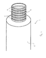
- pipe insulation 1 comprising a conduit 3 and insulating means 5 which takes the form of a layer of insulating material 5 disposed to the outside of the conduit 3 and covering at least a substantial part of the conduit 3 to provide thermal insulation.
- the conduit 3 comprises a flexible, hollow, ribbed tube made from polypropylene plastics material.
- the conduit 3 is also substantially water impermeable to enable condensate to flow down its interior without leaking.
- the layer of insulating material 5 comprises a length of flexible, foamed, closed cell polyethylene (PE) of substantially annular cross section having a durable PE-film covering.
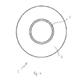
- the insulating material 5 has a central through hole 7 running the length of the material 5 whose internal diameter RD, which in this embodiment is 20mm, is substantially equal to the largest external diameter BD of the conduit 3.
- the conduit 3 is inserted through the hole 7 of the insulating material 5 such that it runs the length of the material 5 from one end to the other. Since the largest external diameter BD of the conduit 3 is substantially equal to the diameter of the central hole 7, the conduit 3 is held in place within the insulating material 5 by interference fit. It may additionally be held in place with the aid of an adhesive.
- the insulating material 5 is chosen such that its external diameter ED is substantially equal to the internal diameter of a condensate drain pipe 30 so that it can be inserted into the drain pipe 30 and held in place by interference fit.
- the diameter of the material 5 is therefore chosen to be approximately 28mm.
- the material 5 is chosen such that it is sufficiently resilient and flexible to bend with the conduit 3 and conform to the shape of a drain pipe 30 which may have bends along its length.
- the insulating material 5 is resiliently compressible so that it can be squeezed into a drain pipe 30 where it returns to its natural state and is held in place.
- the conduit 3 comprises a plurality of substantially parallel spaced apart ribs 9 that extend around the circumference of the conduit 3 along its length. Each rib 9 is separated by a depression 11 which is approximately equal in width to the width of a rib 9.
- the conduit 3 is constructed such that its internal wall is the negative of the external wall. In other words, a depression 11 on the external wall corresponds to a rib on the internal wall and a rib 9 on the external wall corresponds to a depression on the internal wall.
- the depressions 11 that join the ribs 9 together are sufficiently thin to flex under external pressure but the material is resilient enough that each depression returns to its non-flexed state when pressure is released.
- the depressions 11 therefore act as a hinge for the ribs 9 so that one rib 9 can move relative to an adjacent rib 9.
- the conduit 3 can therefore be flexed, bent and curved without kinking thereby permitting it to conform to the shape of a condensate drain pipe 30.
- the conduit 3 also serves as a spine or skeleton for the insulating material 5 which moves with the conduit 3.
- the pipe insulation 1 enable it to conform to the shape of a condensate pipe, it also enables the pipe insulation 1 to be wound around a spool that occupies a relatively small footprint. Large lengths of pipe insulation may therefore be easily transported in, for example, a van.
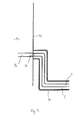
- a pipe insulation installer determines the length of pipe insulation 1 required to line the internal length of a condensate drain pipe 30 from its outlet to its inlet which is connected to the internally run pipe 32 of a dwelling 34 in which the condensing boiler is installed. The installer then cuts an appropriate length of pipe insulation 1 from a reel of pipe insulation and feeds the pipe insulation 1 into the condensate drain pipe 30 when disconnected from the wall 36 of the dwelling 34.
- the installer Having fed the pipe insulation 1 along the length of the condensate drain pipe 30, the installer connects the dwelling wall side 36 end of the pipe insulation 1 to the internally run condensate pipe 32 using a cap 38 made from plastics material which runs between the conduit 3 interior and the internal drain pipe interior to form a water tight seal.
- the cap 38 may effectively seal the end of the insulating material whilst leaving the end of the conduit 3 open so that, when the pipe insulation is inserted into the pipe inlet, fluid will flow down the conduit 3 without wetting the insulating material 5.
- the conduit 3 replaces the external condensate drain pipe as the flow channel and permits the condensate to flow freely and safely away from the condensing boiler.
- a first insulating layer comprises the plastic wall of the condensate drain pipe
- a second insulating layer comprises a layer of air 40 trapped between the insulating material 5 exterior and the condensate drain pipe interior
- a third insulating layer comprises the insulating material 5 itself
- a fourth insulating layer comprises the pockets of air trapped in the channels 15 surrounding the conduit 3
- a fifth insulating layer comprises the plastic wall of the conduit 3.
- the flow of condensate through the conduit 3 is facilitated by the ribbed structure.
- condensate running through the conduit 3 becomes trapped in the depressions formed by the ribs 9 along the conduit interior due to water surface tension thereby causing the conduit interior to be partially lined with water.
- Water tends to flow better over a film of water than the plastic surface of the tube interior and so the rate of flow of condensate along the ribbed structure is increased.
- the ribbed structure gives rise to a more graduated curvature when installed around a sharp bend in a condensate pipe thereby serving to straighten the bend and improve condensate flow which might otherwise collect at a bend.
- the combination of the increased number of insulating layers and the increased flow of condensate helps to keep the condensate from freezing even in very low, sub-zero temperatures, thereby reducing the risk of the condensate pipe freezing up and becoming blocked.
- the insulating means may comprise a series of fins disposed to and extending from the outside of the conduit.
- the fins are arranged around the conduit, parallel to one another and at intervals along the length of the conduit.
- the fins extend substantially perpendicularly out from the outside surface of the conduit a distance approximately equal to the distance between the outside surface of the conduit and the inner surface of the drain pipe when the conduit is centrally located within the pipe.
- the fins maintain the surface of the conduit away from the walls of the pipe so that a thermally insulating layer of air surrounds the conduit.
Landscapes
- Engineering & Computer Science (AREA)
- General Engineering & Computer Science (AREA)
- Mechanical Engineering (AREA)
- Thermal Insulation (AREA)
- Rigid Pipes And Flexible Pipes (AREA)
Applications Claiming Priority (1)
| Application Number | Priority Date | Filing Date | Title |
|---|---|---|---|
| GB1015591.9A GB2483699B (en) | 2010-09-17 | 2010-09-17 | Pipe insulation |
Publications (2)
| Publication Number | Publication Date |
|---|---|
| EP2431649A2 true EP2431649A2 (de) | 2012-03-21 |
| EP2431649A3 EP2431649A3 (de) | 2016-02-24 |
Family
ID=43065404
Family Applications (1)
| Application Number | Title | Priority Date | Filing Date |
|---|---|---|---|
| EP11275105.2A Withdrawn EP2431649A3 (de) | 2010-09-17 | 2011-08-02 | Rohrisolierung |
Country Status (2)
| Country | Link |
|---|---|
| EP (1) | EP2431649A3 (de) |
| GB (1) | GB2483699B (de) |
Family Cites Families (12)
| Publication number | Priority date | Publication date | Assignee | Title |
|---|---|---|---|---|
| US3747646A (en) * | 1970-04-22 | 1973-07-24 | Euratom | Insulation of gas feed tubes |
| FR2257850A1 (en) * | 1974-01-11 | 1975-08-08 | Strulik Wilhelm | Sound and thermally insulated duct system - has thermal insulating medium combined with perforated inner duct |
| US4061162A (en) * | 1976-12-27 | 1977-12-06 | Texaco Inc. | High temperature and shock resistant insulated pipe |
| DE2906397A1 (de) * | 1979-02-20 | 1980-08-28 | Hoechst Ag | Kraftstoffleitung aus kunststoffverbundsystem |
| DE2908414A1 (de) * | 1979-03-03 | 1980-09-11 | Basf Ag | Apparate und rohrleitungen fuer korrosive und heisse gase |
| GB2118672B (en) * | 1982-04-22 | 1986-06-18 | Curtiss Wright Corp | High temperature lined conduits elbows and tees and method of making same |
| US5078182A (en) * | 1989-11-07 | 1992-01-07 | The Babcock & Wilcox Company | Insulated pipe construction |
| US5148836A (en) * | 1990-07-12 | 1992-09-22 | Dayco Products, Inc. | Flexible hose construction |
| DE19749252C1 (de) * | 1997-11-07 | 1999-01-21 | Witzenmann Metallschlauchfab | Flexible Verbundleitung |
| US6116290A (en) * | 1999-03-16 | 2000-09-12 | J. Ray Mcdermott, S.A. | Internally insulated, corrosion resistant pipeline |
| JP2007205551A (ja) * | 2006-02-06 | 2007-08-16 | Mitsubishi Kagaku Sanshi Corp | 温冷水配管 |
| CN201382243Y (zh) * | 2009-02-20 | 2010-01-13 | 招远市天星塑料制品厂 | 一种室外恒温水管 |
-
2010
- 2010-09-17 GB GB1015591.9A patent/GB2483699B/en active Active
-
2011
- 2011-08-02 EP EP11275105.2A patent/EP2431649A3/de not_active Withdrawn
Non-Patent Citations (1)
| Title |
|---|
| None |
Also Published As
| Publication number | Publication date |
|---|---|
| GB2483699A (en) | 2012-03-21 |
| GB2483699B (en) | 2013-11-06 |
| EP2431649A3 (de) | 2016-02-24 |
| GB201015591D0 (en) | 2010-10-27 |
Similar Documents
| Publication | Publication Date | Title |
|---|---|---|
| KR100979968B1 (ko) | 열선이 내장된 보온관 | |
| US4399319A (en) | Thermally insulated composite flexible hose | |
| ES2791763T3 (es) | Tubo para la conducción de un fluido | |
| BR0215375B1 (pt) | conduto rìgido de transporte de hidrocarbonetos. | |
| ES2880296T3 (es) | Instalación hidráulica de calefacción con capacidad de protección contra las heladas | |
| US20050121093A1 (en) | Piping element and manufacturing method and apparatus | |
| EP2431649A2 (de) | Rohrisolierung | |
| JP5329931B2 (ja) | 給水湯管引出し口形成具 | |
| KR101338034B1 (ko) | 동파방지용 급수파이프 및 이를 이용한 이동식화장실의 동파방지시스템 | |
| ES2292523T3 (es) | Dispositivo para el aislamiento de conductos de tubos multiples. | |
| CN208816967U (zh) | 一种耐低温防爆型高密度聚乙烯给水管 | |
| KR101321205B1 (ko) | 벨로우즈 타입용 동파 방지구와 이를 적용한 수도계량기 및 열교환기 | |
| EA036548B1 (ru) | Предварительно изолированный линейный трубный узел и система локального распределения тепла | |
| RU2437025C2 (ru) | Гибкая теплоизолированная труба | |
| TWI788589B (zh) | 管系統及其形成方法 | |
| KR200411561Y1 (ko) | 단열 파이프 커버 구조체 및 단열 파이프 구조체 | |
| CN111305898B (zh) | 一种寒区隧道侧沟用预制保温构件 | |
| JP2004244958A (ja) | 凍結防止用流水配管 | |
| JP2006052759A (ja) | 波形可撓管及びそれの製造方法 | |
| JP2021183905A (ja) | 熱交換器用スペーサ | |
| FI124829B (fi) | Lämmön talteenottopiippu | |
| RU2019115079A (ru) | Гибкая труба | |
| GB2520178A (en) | An improved insulation | |
| KR101212585B1 (ko) | 배수연결관 | |
| KR20170120457A (ko) | 진공단열패널을 이용한 hvac 덕트 및 그 연결체 |
Legal Events
| Date | Code | Title | Description |
|---|---|---|---|
| PUAI | Public reference made under article 153(3) epc to a published international application that has entered the european phase |
Free format text: ORIGINAL CODE: 0009012 |
|
| AK | Designated contracting states |
Kind code of ref document: A2 Designated state(s): AL AT BE BG CH CY CZ DE DK EE ES FI FR GB GR HR HU IE IS IT LI LT LU LV MC MK MT NL NO PL PT RO RS SE SI SK SM TR |
|
| AX | Request for extension of the european patent |
Extension state: BA ME |
|
| PUAL | Search report despatched |
Free format text: ORIGINAL CODE: 0009013 |
|
| AK | Designated contracting states |
Kind code of ref document: A3 Designated state(s): AL AT BE BG CH CY CZ DE DK EE ES FI FR GB GR HR HU IE IS IT LI LT LU LV MC MK MT NL NO PL PT RO RS SE SI SK SM TR |
|
| AX | Request for extension of the european patent |
Extension state: BA ME |
|
| RIC1 | Information provided on ipc code assigned before grant |
Ipc: F16L 59/153 20060101AFI20160119BHEP Ipc: F16L 59/147 20060101ALI20160119BHEP |
|
| STAA | Information on the status of an ep patent application or granted ep patent |
Free format text: STATUS: THE APPLICATION IS DEEMED TO BE WITHDRAWN |
|
| 18D | Application deemed to be withdrawn |
Effective date: 20160825 |