EP2431145B1 - Vorrichtung zum Einbringen von Isoliermaterialien in Lochziegel - Google Patents
Vorrichtung zum Einbringen von Isoliermaterialien in Lochziegel Download PDFInfo
- Publication number
- EP2431145B1 EP2431145B1 EP11007505.8A EP11007505A EP2431145B1 EP 2431145 B1 EP2431145 B1 EP 2431145B1 EP 11007505 A EP11007505 A EP 11007505A EP 2431145 B1 EP2431145 B1 EP 2431145B1
- Authority
- EP
- European Patent Office
- Prior art keywords
- holes
- threader
- threaders
- perforated
- insulating materials
- Prior art date
- Legal status (The legal status is an assumption and is not a legal conclusion. Google has not performed a legal analysis and makes no representation as to the accuracy of the status listed.)
- Active
Links
Images




Classifications
-
- B—PERFORMING OPERATIONS; TRANSPORTING
- B28—WORKING CEMENT, CLAY, OR STONE
- B28B—SHAPING CLAY OR OTHER CERAMIC COMPOSITIONS; SHAPING SLAG; SHAPING MIXTURES CONTAINING CEMENTITIOUS MATERIAL, e.g. PLASTER
- B28B11/00—Apparatus or processes for treating or working the shaped or preshaped articles
- B28B11/04—Apparatus or processes for treating or working the shaped or preshaped articles for coating or applying engobing layers
- B28B11/042—Apparatus or processes for treating or working the shaped or preshaped articles for coating or applying engobing layers with insulating material
- B28B11/043—Apparatus or processes for treating or working the shaped or preshaped articles for coating or applying engobing layers with insulating material filling cavities or chambers of hollow blocks
Definitions
- the invention relates to a device for introducing insulating materials into perforated holes of perforated bricks (bricks), in particular for introducing strip-shaped insulating materials such as rockwool into holes of e.g. made of mineral materials such as perlite, clay clay and the like manufactured perforated bricks, with a supportable on a frame brick receptacle and arranged above the brick receiving, up and down feed device for the insulating materials, the feed elements such as plunger or the like. Has for the insulating materials.
- Hollow bricks often called hollow bricks, are bricks, which are provided with holes for weight reduction and better thermal insulation and holed through.
- hollow bricks and long bricks with the hollow holes in the corresponding holes are perpendicular to the support surface, the slotted tile, however, horizontally to the support surface.
- perforated bricks have a lower density compared to solid bricks, since the mass is controlled by the proportion of holes and the porosity or the choice of raw materials.
- the brick shards can be made by burnout of polystyrene beads, Sawdust, paper fiber and the like made easier and thereby also be set thermally insulating.
- the addition of eg foam polystyrene beads ensures that they burn during the firing process and leave air pores.
- the holes can be stuffed with insulating materials such as rock wool.
- insulating materials such as rock wool.
- a device of the aforementioned type is known in which a robot (feeder), for example, vertically arranged stone wool strips are supplied, which are then lowered by piercing pistons after a corresponding lowering movement of the feeder on the arranged on the brick receiving hole tiles.
- the feeder may be associated with a threading device, which has the hole pattern of Lochziegels corresponding hole recesses and spring plates as Einfädler in number and arrangement, which can be penetrated for a Einbring- and Stopfvorgang of the piercing flask along with the IsoliermaterialstMail and introduced into the holes of the perforated brick ,
- a threading device which has the hole pattern of Lochziegels corresponding hole recesses and spring plates as Einfädler in number and arrangement, which can be penetrated for a Einbring- and Stopfvorgang of the piercing flask along with the IsoliermaterialstMail and introduced into the holes of the perforated brick .
- the porosity of the hole also have the outer walls of the holes of the perforated brick, so that it comes to congestion during insertion of the insulating material with the result that the introduction of the insulating materials in the holes of the perforated brick in the of Manufacturing process required number of cycles is not enforce.
- a generic device for introducing insulating materials in a hole pattern performing holes of perforated bricks is from the EP 1 745 901 A2 already known.
- the device of the type mentioned above is characterized in that the threaders, which are held up and lowered on a threader device, in the number and the arrangement of the hole pattern of perforated bricks adapted support receptacles provided below the feeder, on and pass through movable support portal.
- a device for introducing the insulating materials is created, which is similar to many design details of the device according to the prior art, but certainly prevents the crucial provision of the support portal with the support receptacles that Einfädler in the form of, for example, spring plates in the insertion of the threader in the Holes of the hole brick outwardly buckle, but safely in the holes are to be introduced. Further introduction of the Einfädler together with the insulating materials by the feed is possible without hindrance, the threaders can invest in the outer wall of the holes of the perforated tile, so that the local porosity can no longer hinder the further introduction of insulating materials such as rock wool. Once the insulating material has been inserted, the threaders can be safely removed from the holes of the perforated brick again.
- the support portal together with the support receptacles, to be moved downwards and upwards relative to the feed device.
- the opening dimension of the threader can be widened again, eg, downwards, with respect to the inner dimension of the holes of the perforated brick, so that this contacts the inner wall of the perforation during a further lowering movement of both the support portal and the feeder Holes in the perforated brick.
- the support gantry with such movable adjustment parts which enable it to be moved towards and away from the threaders, thereby enlarging and reducing the geometry of the threader by measuring a controlled stuffing process is possible.
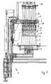
- Fig. 1 to 7 is the embodiment of the device for introducing insulating materials in the hole pattern representing holes of perforated bricks in each matching side view, but shown in different operating positions, with the exception of Fig. 7 in which the machine after a process of introducing insulating materials back in Fig. 1 has taken the basic position shown.
- the generally numbered with 1 device for introducing insulating materials in a hole pattern performing holes 2 of perforated bricks 3 has a supported on a frame 4 brick receptacle 5.
- the frame 4 different frame guides, motor drives, etc. are assigned, which are of interest for the function of the device are of only secondary importance, so that the further explanation and presentation of these device parts is dispensed with.
- a supporting portal 6 the threading device 7 is shown, which has different threading elements 8.
- the threading device 7 has various holes 9.
- the threading elements 8 are to consist of spring plates, for example, in a substantially rectangular configuration with four separate side parts, which may be designed to move toward and away from each other.
- the support portal 6 in turn has support receptacles 10, which are already penetrated by the Einfädelelementen 8 in the basic position.
- the support gantry 6, like the threading device, is guided up and down movably by corresponding motor drives on the frame, wherein the support gantry 6 can also be moved relative to the threading device 7.
- the dimension of the support receptacle 10 is given as 33.1 mm.
- the above the support seat located hole 9 of the threading device 7 is formed larger, so that when a movement of the support portal 6 by a dimension A, the smaller dimension of the support receptacle 10 ensures that the spring plates of the threader 8 in the in Fig. 1
- the support receptacle 10 has a dimension which corresponds to the geometry of the holes 2 of the hole pattern of the perforated brick is, as already the Basic position after Fig. 1 can be seen, this funnel-shaped end 11 of the threader 8 without difficulty in the corresponding hole 2 of the perforated brick 3 to introduce.
- Fig. 2 the threaders are lowered by 80 mm and introduced with their ends 11 straight into the holes 2 of the perforated tile 3.
- the support receptacles 10 surround the respective Soauswandungen the threader 8. In this position, the device is ready that the insulating materials can be introduced.
- the feeding device 12 is brought into position with its feeding elements 13 and the spiked grippers 14, which can move the insulating material, not shown, downwards in the direction of the holes 2.
- the support receptacles 10 of the support portal 6 still surround the Einfädler 8, but are moved with the Einfädemper 8 in the direction of the perforated brick 3 with down so that they locally surround the outer circumferential surface of the threader 8 and locally stiffen it so that it on a Buckling is prevented to the outside.
- This is still in the in Fig. 4 illustrated position of the case where the threaders 8 are substantially completely retracted into the holes 2 of the perforated brick 3 and the grippers now bring the insulating materials, such as stone wool and stuff the holes 2 with rock wool.
- the threaders 8 are raised again via the threading device 7.
- the support portal 6 is moved with the support receptacles 10 upwards, so that it again stiffen the threader 8 locally.
- the spiked grippers 14 remain in position and serve as a stop for the insulating materials, so that they are not brought out of their brought into the holes 2 position by the upward movement of the threader 8.
Landscapes
- Engineering & Computer Science (AREA)
- Structural Engineering (AREA)
- Chemical & Material Sciences (AREA)
- Ceramic Engineering (AREA)
- Mechanical Engineering (AREA)
- Furnace Housings, Linings, Walls, And Ceilings (AREA)
- Devices For Post-Treatments, Processing, Supply, Discharge, And Other Processes (AREA)
- Insulating Bodies (AREA)
Description
- Die Erfindung bezieht sich auf eine Vorrichtung zum Einbringen von Isoliermaterialien in ein Lochmuster darstellende Löcher von Lochziegeln (Mauerziegeln), insbesondere zum Einbringen von streifenförmigen Isoliermaterialien wie Steinwolle in Löcher von z.B. aus mineralischen Materialien wie Perlite, tonhaltigem Lehm und dergleichen gefertigten Lochziegeln, mit einer an einem Gestell abstützbaren Ziegelaufnahme und einer oberhalb der Ziegelaufnahme angeordneten, auf- und absenkbaren Zuführeinrichtung für die Isoliermaterialien, die Zuführelemente wie beispielsweise Stechkolben oder dgl. für die Isoliermaterialien aufweist.
- Lochziegel, vielfach auch Hohlziegel genannt, sind Mauerziegel, die zur Gewichtsminderung und zur besseren Wärmedämmfähigkeit mit Löchern versehen und insgesamt durchlocht sind. Hierbei wird zwischen Hohllochziegeln und Langlochziegeln unterschieden, wobei bei den Hohllochziegeln die entsprechenden Löcher senkrecht zur Auflagefläche verlaufen, beim Langlochziegel hingegen waagerecht zur Auflagefläche. Solche Lochziegel weisen gegenüber Vollziegeln eine geringere Rohdichte auf, da die Masse durch den Lochanteil und die Porosierung bzw. die Rohstoffauswahl gesteuert wird. Die Ziegelscherben können durch Ausbrennstoffe von Polystyrolkügelchen, Sägemehl, Papierfaser und dergleichen leichter gemacht und dadurch auch wärmedämmender eingestellt werden. Durch die Beimischung von z.B. Schaumpolystyrolkügelchen wird erreicht, dass diese beim Brennvorgang verbrennen und Luftporen hinterlassen.
- Zur noch besseren Wärmedämmfähigkeit können die Löcher mit Isoliermaterialien wie Steinwolle ausgestopft werden. Dazu wird angestrebt, dieses Isoliermaterial durch Stopfen in eine automatisierte Fertigung einzubringen. Dazu ist eine Vorrichtung der eingangs genannten Art bekannt, bei der über einen Roboter (Zuführeinrichtung) z.B. stehend angeordnete Steinwollestreifen zugeführt werden, wobei diese dann über Stechkolben nach einer entsprechenden Absenkbewegung der Zuführeinrichtung auf den auf der Ziegelaufnahme angeordneten Lochziegel herabgesenkt werden. Zudem kann der Zuführeinrichtung eine Einfädelvorrichtung zugeordnet sein, die in Anzahl und Anordnung dem Lochmuster des Lochziegels entsprechende Lochausnehmungen und Federbleche als Einfädler hat, die für einen Einbring- und Stopfvorgang von den Stechkolben mitsamt den Isoliermaterialstreifen durchdrungen werden können und in die Löcher des Lochziegels eingebracht werden. Dabei erweist es sich allerdings als außerordentlich erschwerend, dass die Porigkeit des Lochsteins auch die Außenwände der Löcher des Lochziegels aufweisen, so dass es zu Stauungen beim Einbringen des Isoliermaterials kommt mit dem Ergebnis, dass das Einbringen der Isoliermaterialien in die Löcher des Lochziegels in der vom Fertigungsvorgang geforderten Taktzahl nicht zu vollziehen ist. Vielfach sind die Löcher des Lochziegels nicht in einem zufriedenstellenden Maße mit den Isoliermaterialien zu versehen.
- Auch die an der Einfädelvorrichtung angebrachten Federbleche, die in den Lochziegel eingebracht werden, führen nicht zu befriedigenden Ergebnissen, weil die dem Lochziegel zugewandten Enden der Federbleche vielfach beim Absenkvorgang auf den Lochziegel gelangen und auf dessen Auflageflächen zur Anlage kommen mit dem Ergebnis eines nach außen hin gerichteten Ausknickens. Im Fertigungsprozess führte dies dazu, dass durch Ausknicken unbrauchbar gewordene Federbleche auszutauschen sind mit den damit einhergehenden Stillstandzeiten der Vorrichtung und den mit dem Austausch verbundenen Kosten.
- Eine gattungsgemäße Vorrichtung zum Einbringen von Isoliermaterialien in ein Lochmuster darstellende Löcher von Lochziegeln ist aus der
EP 1 745 901 A2 bereits bekannt. - Es ist Aufgabe der vorliegenden Erfindung, eine Vorrichtung der eingangs genannten Art zu schaffen, mit der Isoliermaterialien sicher in Löcher eines Lochziegels einzubringen sind.
- Zur Lösung dieser Aufgabe zeichnet sich die Vorrichtung der eingangs genannten Art dadurch aus, dass die Einfädler, die an einer Einfädlervorrichtung auf- und absenkbar gehaltert sind, in der Anzahl und der Anordnung dem Lochmuster der Lochziegel angepasste Stützaufnahmen eines unterhalb der Zuführungseinrichtung vorgesehenen, auf- und abbewegbare Stützportals durchgreifen.
- Damit ist eine Vorrichtung zum Einbringen der Isoliermaterialien geschaffen, die von vielen Konstruktionsdetails der Vorrichtung nach dem Stand der Technik gleicht, die allerdings durch das entscheidende Vorsehen des Stützportals mit den Stützaufnahmen sicher verhindert, dass Einfädler in Gestalt von z.B. Federblechen beim Einführen der Einfädler in die Löcher des Lochziegels nach außen hin ausknicken, sondern sicher in die Löcher einzubringen sind. Ein weiteres Einbringen der Einfädler mitsamt den Isoliermaterialien durch die Zuführelemente ist ungehindert möglich, wobei die Einfädler sich an die Außenwandung der Löcher des Lochziegels anlegen können, so dass die dortige Porigkeit das weitere Einbringen der Isoliermaterialien wie Steinwolle nicht mehr weiter behindern kann. Ist das Isoliermaterial eingebracht, können die Einfädler wieder sicher aus den Löchern des Lochziegels herausgebracht werden.
- Um den Einfädelvorgang noch weiter zu optimieren, ist darüber hinaus in einer vorteilhaften Ausgestaltung der Erfindung vorgesehen, dass das Stützportal mitsamt den Stützaufnahmen relativ zu der Zuführeinrichtung nach unten und nach oben zu bewegen ist. Durch eine geschickte Abstimmung der Aufnahmen bzw. Lochgeometrien im Hinblick auf die Geometrie der Löcher des Lochziegels ist darüber hinaus sicherzustellen, dass bei einer Absenkbewegung des Stützportals relativ zur Einfädelvorrichtung die Einfädler in z.B. Gestalt von vier Federblechteilen eine trichterförmige Gestalt einnehmen mit einem Trichterende, das ein kleineres lichtes Maß aufweist als die Löcher des Lochziegels. Sind die Einfädler in die Löcher eingeführt, kann durch eine Bewegung z.B. nach unten das Öffnungsmaß der Einfädler gegenüber dem Innenmaß der Löcher des Lochziegels wieder erweitert werden, so dass sich dieses im Verlaufe einer weiteren Absenkbewegung sowohl des Stützportals als auch der Zuführeinrichtung an die Innenwandung der Löcher des Lochziegels anlegt.
- Alternativ oder zusätzlich ist es möglich, das Stützportal mit solchen beweglichen Justierteilen zu versehen, die es ermöglichen, auf die Einfädler zu- und von diesen weg bewegt zu werden, um dadurch die Geometrie bzw. den Einfädler durch Messen zu vergrößern und zu verkleinern, wodurch ein gesteuerter Stopfvorgang ermöglicht ist.
- Hinsichtlich weiterer vorteilhafter Ausgestaltungen der Erfindung wird auf weitere Unteransprüche, die nachfolgende Beschreibung und die Zeichnung verwiesen. In der Zeichnung zeigen jeweils in einer schematischen Seitenansicht:
- Fig. 1
- ein Ausführungsbeispiel nach der Erfindung in der Grundstellung;
- Fig. 2
- das Ausführungsbeispiel nach
Fig. 1 , bei der die Einfädler über die Zuführeinrichtung um ein gewisses Maß abgesenkt sind; - Fig. 3
- ein relatives Absenken des Stützportals gegenüber der Zuführeinrichtung mit Zuführung der Isoliermaterialstreifen mittels Stachelgreifer;
- Fig. 4
- ein weiteres Absenken der Zuführeinrichtung mit einer Relativbewegung des Stützportals und Einführen der Isoliermaterialien mittels der Stachelgreifer;
- Fig. 5
- Anheben des Stützportals und der Zuführeinrichtung, wobei die Stachelgreifer als Anschlag für die Wolle in Position bleiben;
- Fig. 6
- Anheben der Stachelgreifer und Ausbringen aus den Einfädlern und der Zuführeinrichtung;
- Fig. 7
- Einnehmen der Grundstellung.
- In der Zeichnung sind grundsätzlich gleichwirkende Teile mit übereinstimmenden Bezugsziffern versehen.
- In den
Fig. 1 bis 7 ist das Ausführungsbeispiel der Vorrichtung zum Einbringen von Isoliermaterialien in die ein Lochmuster darstellenden Löcher von Lochziegeln in jeweils übereinstimmender Seitenansicht, aber in jeweils verschiedenen Betriebsstellungen dargestellt, mit Ausnahme vonFig. 7 , in der die Maschine nach einem Einbringvorgang von Isoliermaterialien wieder die inFig. 1 dargestellte Grundstellung eingenommen hat. Die allgemein mit 1 bezifferte Vorrichtung zum Einbringen von Isoliermaterialien in ein Lochmuster darstellende Löcher 2 von Lochziegeln 3 hat eine an einem Gestell 4 abgestützte Ziegelaufnahme 5. Dem Gestell 4 sind verschiedene Gestellführungen, motorische Antriebe usw. zugeordnet, die für die hier interessierende Funktion der Vorrichtung von nur zweitrangiger Bedeutung sind, so dass auf die nähere Erläuterung und Darstellung dieser Vorrichtungsteile abgesehen wird. - In der in
Fig. 1 gezeigten Grundstellung ist die Zuführeinrichtung mit den Zuführelementen noch nicht gezeigt. Oberhalb eines Stützportals 6 ist die Einfädelvorrichtung 7 dargestellt, die verschiedene Einfädelelemente 8 aufweist. Die Einfädelvorrichtung 7 hat verschiedene Löcher 9. Die Einfädelelemente 8 sollen aus Federblechen bestehen, z.B. in einer im Wesentlichen rechteckigen Ausbildung mit vier separaten Seitenteilen, die aufeinander zu und voneinander weg bewegbar ausgebildet sein können. Das Stützportal 6 seinerseits hat Stützaufnahmen 10, die schon in der Grundstellung von den Einfädelelementen 8 durchgriffen werden. Das Stützportal 6 ist genauso wie die Einfädelvorrichtung auf- und abbeweglich durch entsprechende motorische Antriebe an dem Gestell geführt, wobei das Stützportal 6 auch relativ zu der Einfädelvorrichtung 7 bewegt werden kann. In der Darstellung nachFig. 1 ist das Maß der Stützaufnahme 10 mit 33,1 mm angegeben. Das oberhalb der Stützaufnahme gelegene Loch 9 der Einfädelvorrichtung 7 ist größer ausgebildet, so dass bei einer Verfahrbewegung des Stützportals 6 um ein Maß A das geringere Maß der Stützaufnahme 10 dafür sorgt, dass sich die Federbleche der Einfädler 8 in die inFig. 1 gezeigte Trichterform bewegen mit einem Trichterende 11, das ein geringeres Maß aufweist als das Maß der Stützaufnahme 10 bzw. des Loches 9. Da die Stützaufnahme 10 ein Maß hat, was der Geometrie der Löcher 2 des Lochmusters des Lochziegels entspricht, ist, wie schon der Grundstellung nachFig. 1 zu entnehmen ist, ist dieses trichterförmige Ende 11 des Einfädlers 8 ohne Schwierigkeiten in das entsprechende Loch 2 des Lochziegels 3 einzuführen. - In
Fig. 2 sind die Einfädler um 80 mm abgesenkt und mit ihren Enden 11 gerade in die Löcher 2 des Lochziegels 3 eingebracht. Die Stützaufnahmen 10 umgreifen die jeweiligen Seitenauswandungen der Einfädler 8. In dieser Position ist die Vorrichtung bereit, dass die Isoliermaterialien eingebracht werden können. - Dazu ist in
Fig. 3 die Zuführeinrichtung 12 in Position gebracht mit ihren Zuführelementen 13 und den Stachelgreifern 14, die das nicht näher dargestellte Isoliermaterial nach unten in Richtung der Löcher 2 bewegen können. Die Stützaufnahmen 10 des Stützportals 6 umgreifen immer noch die Einfädler 8, sind jedoch mit den Einfädlern 8 in Richtung auf den Lochziegel 3 mit nach unten bewegt, so dass sie örtlich die Außenmantelfläche des Einfädlers 8 umgreifen und diese örtlich aussteifen, so dass er an einem Ausknicken nach außen gehindert ist. Dies ist auch noch in der inFig. 4 dargestellten Stellung der Fall, wo die Einfädler 8 im Wesentlichen ganz in die Löcher 2 des Lochziegels 3 eingefahren sind und die Greifer nun die Isoliermaterialien, beispielsweise die Steinwolle einbringen und die Löcher 2 mit Steinwolle ausstopfen. - In der
Fig. 5 sind die Einfädler 8 über die Einfädelvorrichtung 7 wieder hochgefahren. Parallel ist auch das Stützportal 6 mit den Stützaufnahmen 10 nach oben bewegt, so dass es wiederum örtlich die Einfädler 8 aussteift. Die Stachelgreifer 14 sind in Position verblieben und dienen als Anschlag für die Isoliermaterialien, damit diese durch die Heraufbewegung der Einfädler 8 nicht aus ihrer in die Löcher 2 eingebrachten Position herausgebracht werden. - In der Darstellung nach
Fig. 6 sind auch die Stachelgreifer 14 wieder aus den Löchern 2 und den Einfädlern 8 herausbewegt und die Zuführeinrichtung 12 ist aus der Vorrichtung wegbewegt. Danach nehmen die Teile die inFig. 7 dargestellte Grundstellung wieder ein, wie sie bereits im Zusammenhang mitFig. 1 erläutert wurde.
Claims (8)
- Vorrichtung (1) zum Einbringen von Isoliermaterialien in ein Lochmuster darstellende Löcher (2) von Lochziegeln (3) insbesondere zum Zuführen von streifenförmigen Isoliermaterialien wie Steinwolle in Löcher (2) von z.B. aus mineralischen Materialien wie Perlite, Ton und dergleichen gefertigten Lochziegeln (3), mit einer an einem Gestell (4) abstützbaren Ziegelaufnahme (5) sowie mit an einer auf- und absenkbaren Zuführeinrichtung (12) für die Isoliermaterialien vorgesehenen, in Anzahl und Anordnung dem Lochmuster der Löcher (2) der Lochziegel (3) angepassten Zuführelemente (13, 14) für die Isoliermaterialien, wobei die Zuführelemente (13, 14) in die Löcher (2) der Lochziegel (3) einführbar und aus diesen herausnehmbar sind und den Zuführelementen (13, 14) insbesondere als Federbleche ausgebildete Einfädler (8) zugeordnet sind, dadurch gekennzeichnet, dass die Einfädler an einer Einfädlervorrichtung (7) auf- und absenkbar gehaltert und dass die Einfädler (8) in Anzahl und Anordnung dem Lochmuster der Lochziegel (3) angepasste Stützaufnahmen (10) eines unterhalb der Zuführungseinrichtung (12) und der Einfädlervorrichtung (7) vorgesehenen, auf- und abbewegbaren Stützportals (6) durchgreifen.
- Vorrichtung nach Anspruch 1, dadurch gekennzeichnet, dass das Stützportal (6) relativ zur Zuführungseinrichtung (12) und relativ zu Einfädlervorrichtung (7) auf- und abbewegbar ist.
- Vorrichtung nach Anspruch 1 oder 2, dadurch gekennzeichnet, dass das Stützportal (6) oberhalb der Ziegelaufnahme (5) und unterhalb der.Zuführeinrichtung (12) und der Einfädlervorrichtung (7) auf- und abbeweglich an dem Gestell abstützbar ist.
- Vorrichtung nach einem der Ansprüche 1 bis 3, dadurch gekennzeichnet, dass die Einfädler (8) an der Einfädlervorrichtung (7) derart angeordnet sind, dass die Geometrie von Löchern (9) der Einfädlervorrichtung (7) größer ausgebildet sind als die Löcher (2) des Lochmusters der Lochsteine (3).
- Vorrichtung nach einem der Ansprüche 1 bis 4, dadurch gekennzeichnet, dass die Stützaufnahmen (10) des auf- und absenkbaren Stützportals (6) in Anzahl, Anordnung und Geometrie den Löchern (2) des Lochmusters des Lochziegels (3) entsprechen.
- Vorrichtung nach einem der Ansprüche 1 bis 5, dadurch gekennzeichnet, dass durch eine Relativbewegung des Stützportals (6) zu der Einfädlervorrichtung (7) die Einfädler (8) in eine trichterförmige Form bringbar sind und durch eine Relativbewegung auf die Einfädlervorrichtung (7) ein trichterförmiger Einfädler (8) aufweitbar ist.
- Vorrichtung nach Anspruch 6, dadurch gekennzeichnet, dass die Einfädler (8) mehrere Seitenwandbereiche haben, die aufeinander zu und voneinander weg bewegbar sind.
- Vorrichtung nach einem der Ansprüche 1 bis 7, dadurch gekennzeichnet, dass das Stützportal (6) zu den Einfädlern (8) relativ bewegliche Justierteile haben, mit denen die Geometrie der Stützaufnahmen (10) veränderlich ist.
Priority Applications (1)
| Application Number | Priority Date | Filing Date | Title |
|---|---|---|---|
| PL11007505T PL2431145T3 (pl) | 2010-09-21 | 2011-09-14 | Urządzenie do wprowadzania materiałów izolacyjnych do cegieł dziurawek |
Applications Claiming Priority (1)
| Application Number | Priority Date | Filing Date | Title |
|---|---|---|---|
| DE102010045927A DE102010045927B4 (de) | 2010-09-21 | 2010-09-21 | Vorrichtung zum Einbringen von Isoliermaterialien in Lochziegel |
Publications (3)
| Publication Number | Publication Date |
|---|---|
| EP2431145A2 EP2431145A2 (de) | 2012-03-21 |
| EP2431145A3 EP2431145A3 (de) | 2014-05-14 |
| EP2431145B1 true EP2431145B1 (de) | 2014-10-22 |
Family
ID=44883044
Family Applications (1)
| Application Number | Title | Priority Date | Filing Date |
|---|---|---|---|
| EP11007505.8A Active EP2431145B1 (de) | 2010-09-21 | 2011-09-14 | Vorrichtung zum Einbringen von Isoliermaterialien in Lochziegel |
Country Status (4)
| Country | Link |
|---|---|
| EP (1) | EP2431145B1 (de) |
| DE (1) | DE102010045927B4 (de) |
| ES (1) | ES2527726T3 (de) |
| PL (1) | PL2431145T3 (de) |
Families Citing this family (2)
| Publication number | Priority date | Publication date | Assignee | Title |
|---|---|---|---|---|
| DE102016008020B4 (de) * | 2016-07-04 | 2021-01-28 | Keller Hcw Gmbh | Vorrichtung und Verfahren zum Verbringen von Isoliermaterialien in Lochziegel |
| CN112171872B (zh) * | 2020-09-18 | 2021-11-26 | 罗爱灵 | 一种瓦当制作上釉设备 |
Family Cites Families (6)
| Publication number | Priority date | Publication date | Assignee | Title |
|---|---|---|---|---|
| FI820567A7 (fi) * | 1980-06-23 | 1982-02-22 | Faerila Laettblock Ab | Menetelmä ja laite eristysaineen sullomiseksi onttoihin harkkoihin. |
| SE8004635L (sv) * | 1980-06-23 | 1981-12-24 | Ferila Lettblock Ab | Maskin for isolering av halblock |
| EP1745901B1 (de) * | 2005-07-21 | 2017-09-06 | Rockwool International A/S | Verfahren und Vorrichtung zur Herstellung eines Formsteins |
| DE102006022516A1 (de) * | 2005-07-21 | 2007-02-01 | Deutsche Rockwool Mineralwoll Gmbh + Co Ohg | Verfahren und Vorrichtung zur Herstellung eines Formsteins, Formstein und Bauwerk bestehend aus mindestens zwei Formsteinen |
| DE102006002281B4 (de) * | 2006-01-18 | 2008-04-24 | Deutsche Rockwool Mineralwoll Gmbh + Co Ohg | Verfahren zum Einbringen eines Dämmstoffs in einen Hohlraum eines Mauersteins |
| DE202009017904U1 (de) * | 2009-03-18 | 2010-07-01 | Hans Lingl Anlagenbau Und Verfahrenstechnik Gmbh & Co. Kg | Vorrichtung zum Befüllen von Formkörpern mit Füllstücken |
-
2010
- 2010-09-21 DE DE102010045927A patent/DE102010045927B4/de not_active Expired - Fee Related
-
2011
- 2011-09-14 PL PL11007505T patent/PL2431145T3/pl unknown
- 2011-09-14 EP EP11007505.8A patent/EP2431145B1/de active Active
- 2011-09-14 ES ES11007505.8T patent/ES2527726T3/es active Active
Also Published As
| Publication number | Publication date |
|---|---|
| DE102010045927B4 (de) | 2012-12-20 |
| PL2431145T3 (pl) | 2015-03-31 |
| EP2431145A2 (de) | 2012-03-21 |
| ES2527726T3 (es) | 2015-01-29 |
| DE102010045927A1 (de) | 2012-03-22 |
| EP2431145A3 (de) | 2014-05-14 |
Similar Documents
| Publication | Publication Date | Title |
|---|---|---|
| DE102015113077B4 (de) | Schalform für ein Bauelement und Verfahren zum Ausschalen | |
| EP3003601B1 (de) | Speisereinsatz, formelement für den speisereinsatz und verfahren zum giessen von metall unter verwendung derselben | |
| EP3165659B1 (de) | Nadelmodul für ein nadelbrett einer nadelmaschine | |
| DE102010045927B4 (de) | Vorrichtung zum Einbringen von Isoliermaterialien in Lochziegel | |
| DE102010008652B4 (de) | Dochthalter, insbesondere für Teelichter und Verfahren zu seiner Herstellung | |
| DE2213545C3 (de) | Verfahren und Vorrichtung zum Schneiden von dick gelegter Milch | |
| EP2587261A1 (de) | Tablettenteststation | |
| EP3266574B1 (de) | Vorrichtung und verfahren zum verbringen von isoliermaterialien in lochziegel | |
| EP2014843A2 (de) | Mauerstein mit Dämmmaterial | |
| EP2718071A1 (de) | Steinformmaschine und verfahren zur höhenverstellung einer steinformmaschine | |
| EP2724832B1 (de) | Verfahren zur herstellung eines mauersteins mit dämmfüllung | |
| EP2395153B1 (de) | Verfahren und Vorrichtung zum Herstellen von Wandlamellen im Boden | |
| EP3075504A1 (de) | Vorrichtung zur herstellung von betonformteilen in einer formmaschine | |
| DE2909690C2 (de) | Verfahren und Vorrichtung zum Herstellen einer Aufhängeösen an einem aus Draht bestehenden Bindeelement | |
| DE29515577U1 (de) | Mauerwerkstein / Bausatz | |
| DE3807136A1 (de) | Verfahren zum sanieren von kaminen und vorrichtungen zum durchfuehren der einzelnen verfahrensschritte | |
| DE102005058404B4 (de) | Vorrichtung zur Herstellung von Betonformsteinen sowie Formensystem und Formeinsatz hierfür | |
| EP2183083A2 (de) | Verfahren und vorrichtung zur herstellung eines beton-deckenelements | |
| DE112020005032T5 (de) | Vorrichtung und Verfahren zur Herstellung eines Glasartikels | |
| EP1898503B1 (de) | Crimpvorrichtung | |
| WO2008138635A1 (de) | Befüllmagazin zum befüllen von schachtschragen sowie befüllstation mit einem solchen befüllmagazin | |
| DE2224441C3 (de) | Verfahren zum Beschicken von Pressformen, vorzugsweise mit einem schütt- aber nicht steigfähigen Gemisch von organischen oder mineralischen Faserstoffen und einem Bindemittel, sowie Vorrichtung zur Durchführung des Verfahrens | |
| DE202016009080U1 (de) | Ziehdornvorrichtung für eine Steinformmaschine und Steinformmaschine | |
| DE247374C (de) | ||
| EP4648914A1 (de) | Additive fertigungsvorrichtung und rüstverfahren |
Legal Events
| Date | Code | Title | Description |
|---|---|---|---|
| PUAI | Public reference made under article 153(3) epc to a published international application that has entered the european phase |
Free format text: ORIGINAL CODE: 0009012 |
|
| AK | Designated contracting states |
Kind code of ref document: A2 Designated state(s): AL AT BE BG CH CY CZ DE DK EE ES FI FR GB GR HR HU IE IS IT LI LT LU LV MC MK MT NL NO PL PT RO RS SE SI SK SM TR |
|
| AX | Request for extension of the european patent |
Extension state: BA ME |
|
| PUAL | Search report despatched |
Free format text: ORIGINAL CODE: 0009013 |
|
| AK | Designated contracting states |
Kind code of ref document: A3 Designated state(s): AL AT BE BG CH CY CZ DE DK EE ES FI FR GB GR HR HU IE IS IT LI LT LU LV MC MK MT NL NO PL PT RO RS SE SI SK SM TR |
|
| AX | Request for extension of the european patent |
Extension state: BA ME |
|
| RIC1 | Information provided on ipc code assigned before grant |
Ipc: B28B 11/04 20060101AFI20140404BHEP |
|
| 17P | Request for examination filed |
Effective date: 20140522 |
|
| GRAP | Despatch of communication of intention to grant a patent |
Free format text: ORIGINAL CODE: EPIDOSNIGR1 |
|
| INTG | Intention to grant announced |
Effective date: 20140718 |
|
| GRAS | Grant fee paid |
Free format text: ORIGINAL CODE: EPIDOSNIGR3 |
|
| RBV | Designated contracting states (corrected) |
Designated state(s): AL AT BE BG CH CY CZ DE DK EE ES FI FR GB GR HR HU IE IS IT LI LT LU LV MC MK MT NL NO PL PT RO RS SE SI SK SM TR |
|
| GRAA | (expected) grant |
Free format text: ORIGINAL CODE: 0009210 |
|
| AK | Designated contracting states |
Kind code of ref document: B1 Designated state(s): AL AT BE BG CH CY CZ DE DK EE ES FI FR GB GR HR HU IE IS IT LI LT LU LV MC MK MT NL NO PL PT RO RS SE SI SK SM TR |
|
| REG | Reference to a national code |
Ref country code: GB Ref legal event code: FG4D Free format text: NOT ENGLISH |
|
| REG | Reference to a national code |
Ref country code: CH Ref legal event code: EP |
|
| REG | Reference to a national code |
Ref country code: AT Ref legal event code: REF Ref document number: 692393 Country of ref document: AT Kind code of ref document: T Effective date: 20141115 |
|
| REG | Reference to a national code |
Ref country code: IE Ref legal event code: FG4D Free format text: LANGUAGE OF EP DOCUMENT: GERMAN |
|
| REG | Reference to a national code |
Ref country code: DE Ref legal event code: R096 Ref document number: 502011004725 Country of ref document: DE Effective date: 20141204 |
|
| REG | Reference to a national code |
Ref country code: CH Ref legal event code: NV Representative=s name: SCHNEIDER FELDMANN AG PATENT- UND MARKENANWAEL, CH |
|
| REG | Reference to a national code |
Ref country code: NL Ref legal event code: T3 |
|
| REG | Reference to a national code |
Ref country code: ES Ref legal event code: FG2A Ref document number: 2527726 Country of ref document: ES Kind code of ref document: T3 Effective date: 20150129 |
|
| REG | Reference to a national code |
Ref country code: LT Ref legal event code: MG4D |
|
| REG | Reference to a national code |
Ref country code: PL Ref legal event code: T3 |
|
| REG | Reference to a national code |
Ref country code: SK Ref legal event code: T3 Ref document number: E 17872 Country of ref document: SK |
|
| REG | Reference to a national code |
Ref country code: GR Ref legal event code: EP Ref document number: 20150400005 Country of ref document: GR Effective date: 20150220 |
|
| PG25 | Lapsed in a contracting state [announced via postgrant information from national office to epo] |
Ref country code: PT Free format text: LAPSE BECAUSE OF FAILURE TO SUBMIT A TRANSLATION OF THE DESCRIPTION OR TO PAY THE FEE WITHIN THE PRESCRIBED TIME-LIMIT Effective date: 20150223 Ref country code: NO Free format text: LAPSE BECAUSE OF FAILURE TO SUBMIT A TRANSLATION OF THE DESCRIPTION OR TO PAY THE FEE WITHIN THE PRESCRIBED TIME-LIMIT Effective date: 20150122 Ref country code: IS Free format text: LAPSE BECAUSE OF FAILURE TO SUBMIT A TRANSLATION OF THE DESCRIPTION OR TO PAY THE FEE WITHIN THE PRESCRIBED TIME-LIMIT Effective date: 20150222 Ref country code: FI Free format text: LAPSE BECAUSE OF FAILURE TO SUBMIT A TRANSLATION OF THE DESCRIPTION OR TO PAY THE FEE WITHIN THE PRESCRIBED TIME-LIMIT Effective date: 20141022 Ref country code: LT Free format text: LAPSE BECAUSE OF FAILURE TO SUBMIT A TRANSLATION OF THE DESCRIPTION OR TO PAY THE FEE WITHIN THE PRESCRIBED TIME-LIMIT Effective date: 20141022 |
|
| PG25 | Lapsed in a contracting state [announced via postgrant information from national office to epo] |
Ref country code: HR Free format text: LAPSE BECAUSE OF FAILURE TO SUBMIT A TRANSLATION OF THE DESCRIPTION OR TO PAY THE FEE WITHIN THE PRESCRIBED TIME-LIMIT Effective date: 20141022 Ref country code: RS Free format text: LAPSE BECAUSE OF FAILURE TO SUBMIT A TRANSLATION OF THE DESCRIPTION OR TO PAY THE FEE WITHIN THE PRESCRIBED TIME-LIMIT Effective date: 20141022 Ref country code: LV Free format text: LAPSE BECAUSE OF FAILURE TO SUBMIT A TRANSLATION OF THE DESCRIPTION OR TO PAY THE FEE WITHIN THE PRESCRIBED TIME-LIMIT Effective date: 20141022 Ref country code: CY Free format text: LAPSE BECAUSE OF FAILURE TO SUBMIT A TRANSLATION OF THE DESCRIPTION OR TO PAY THE FEE WITHIN THE PRESCRIBED TIME-LIMIT Effective date: 20141022 Ref country code: SE Free format text: LAPSE BECAUSE OF FAILURE TO SUBMIT A TRANSLATION OF THE DESCRIPTION OR TO PAY THE FEE WITHIN THE PRESCRIBED TIME-LIMIT Effective date: 20141022 |
|
| REG | Reference to a national code |
Ref country code: DE Ref legal event code: R097 Ref document number: 502011004725 Country of ref document: DE |
|
| PG25 | Lapsed in a contracting state [announced via postgrant information from national office to epo] |
Ref country code: EE Free format text: LAPSE BECAUSE OF FAILURE TO SUBMIT A TRANSLATION OF THE DESCRIPTION OR TO PAY THE FEE WITHIN THE PRESCRIBED TIME-LIMIT Effective date: 20141022 Ref country code: RO Free format text: LAPSE BECAUSE OF FAILURE TO SUBMIT A TRANSLATION OF THE DESCRIPTION OR TO PAY THE FEE WITHIN THE PRESCRIBED TIME-LIMIT Effective date: 20141022 Ref country code: DK Free format text: LAPSE BECAUSE OF FAILURE TO SUBMIT A TRANSLATION OF THE DESCRIPTION OR TO PAY THE FEE WITHIN THE PRESCRIBED TIME-LIMIT Effective date: 20141022 |
|
| PLBE | No opposition filed within time limit |
Free format text: ORIGINAL CODE: 0009261 |
|
| STAA | Information on the status of an ep patent application or granted ep patent |
Free format text: STATUS: NO OPPOSITION FILED WITHIN TIME LIMIT |
|
| 26N | No opposition filed |
Effective date: 20150723 |
|
| PG25 | Lapsed in a contracting state [announced via postgrant information from national office to epo] |
Ref country code: SI Free format text: LAPSE BECAUSE OF FAILURE TO SUBMIT A TRANSLATION OF THE DESCRIPTION OR TO PAY THE FEE WITHIN THE PRESCRIBED TIME-LIMIT Effective date: 20141022 |
|
| PG25 | Lapsed in a contracting state [announced via postgrant information from national office to epo] |
Ref country code: LU Free format text: LAPSE BECAUSE OF FAILURE TO SUBMIT A TRANSLATION OF THE DESCRIPTION OR TO PAY THE FEE WITHIN THE PRESCRIBED TIME-LIMIT Effective date: 20150914 Ref country code: MC Free format text: LAPSE BECAUSE OF FAILURE TO SUBMIT A TRANSLATION OF THE DESCRIPTION OR TO PAY THE FEE WITHIN THE PRESCRIBED TIME-LIMIT Effective date: 20141022 |
|
| GBPC | Gb: european patent ceased through non-payment of renewal fee |
Effective date: 20150914 |
|
| REG | Reference to a national code |
Ref country code: IE Ref legal event code: MM4A |
|
| PG25 | Lapsed in a contracting state [announced via postgrant information from national office to epo] |
Ref country code: IE Free format text: LAPSE BECAUSE OF NON-PAYMENT OF DUE FEES Effective date: 20150914 Ref country code: GB Free format text: LAPSE BECAUSE OF NON-PAYMENT OF DUE FEES Effective date: 20150914 |
|
| REG | Reference to a national code |
Ref country code: FR Ref legal event code: PLFP Year of fee payment: 6 |
|
| PG25 | Lapsed in a contracting state [announced via postgrant information from national office to epo] |
Ref country code: MT Free format text: LAPSE BECAUSE OF FAILURE TO SUBMIT A TRANSLATION OF THE DESCRIPTION OR TO PAY THE FEE WITHIN THE PRESCRIBED TIME-LIMIT Effective date: 20141022 |
|
| PG25 | Lapsed in a contracting state [announced via postgrant information from national office to epo] |
Ref country code: BG Free format text: LAPSE BECAUSE OF FAILURE TO SUBMIT A TRANSLATION OF THE DESCRIPTION OR TO PAY THE FEE WITHIN THE PRESCRIBED TIME-LIMIT Effective date: 20141022 Ref country code: HU Free format text: LAPSE BECAUSE OF FAILURE TO SUBMIT A TRANSLATION OF THE DESCRIPTION OR TO PAY THE FEE WITHIN THE PRESCRIBED TIME-LIMIT; INVALID AB INITIO Effective date: 20110914 Ref country code: SM Free format text: LAPSE BECAUSE OF FAILURE TO SUBMIT A TRANSLATION OF THE DESCRIPTION OR TO PAY THE FEE WITHIN THE PRESCRIBED TIME-LIMIT Effective date: 20141022 |
|
| PG25 | Lapsed in a contracting state [announced via postgrant information from national office to epo] |
Ref country code: TR Free format text: LAPSE BECAUSE OF FAILURE TO SUBMIT A TRANSLATION OF THE DESCRIPTION OR TO PAY THE FEE WITHIN THE PRESCRIBED TIME-LIMIT Effective date: 20141022 |
|
| REG | Reference to a national code |
Ref country code: FR Ref legal event code: PLFP Year of fee payment: 7 |
|
| PG25 | Lapsed in a contracting state [announced via postgrant information from national office to epo] |
Ref country code: MK Free format text: LAPSE BECAUSE OF FAILURE TO SUBMIT A TRANSLATION OF THE DESCRIPTION OR TO PAY THE FEE WITHIN THE PRESCRIBED TIME-LIMIT Effective date: 20141022 |
|
| REG | Reference to a national code |
Ref country code: FR Ref legal event code: PLFP Year of fee payment: 8 |
|
| PG25 | Lapsed in a contracting state [announced via postgrant information from national office to epo] |
Ref country code: AL Free format text: LAPSE BECAUSE OF FAILURE TO SUBMIT A TRANSLATION OF THE DESCRIPTION OR TO PAY THE FEE WITHIN THE PRESCRIBED TIME-LIMIT Effective date: 20141022 |
|
| REG | Reference to a national code |
Ref country code: CH Ref legal event code: PFA Owner name: KELLER HCW GMBH, DE Free format text: FORMER OWNER: KELLER HCW GMBH, DE |
|
| PGFP | Annual fee paid to national office [announced via postgrant information from national office to epo] |
Ref country code: DE Payment date: 20230511 Year of fee payment: 13 |
|
| PGFP | Annual fee paid to national office [announced via postgrant information from national office to epo] |
Ref country code: GR Payment date: 20240918 Year of fee payment: 14 |
|
| PGFP | Annual fee paid to national office [announced via postgrant information from national office to epo] |
Ref country code: BE Payment date: 20240920 Year of fee payment: 14 |
|
| PGFP | Annual fee paid to national office [announced via postgrant information from national office to epo] |
Ref country code: FR Payment date: 20240924 Year of fee payment: 14 |
|
| PGFP | Annual fee paid to national office [announced via postgrant information from national office to epo] |
Ref country code: NL Payment date: 20240920 Year of fee payment: 14 |
|
| PGFP | Annual fee paid to national office [announced via postgrant information from national office to epo] |
Ref country code: CZ Payment date: 20240830 Year of fee payment: 14 |
|
| PGFP | Annual fee paid to national office [announced via postgrant information from national office to epo] |
Ref country code: AT Payment date: 20240918 Year of fee payment: 14 |
|
| PGFP | Annual fee paid to national office [announced via postgrant information from national office to epo] |
Ref country code: PL Payment date: 20240830 Year of fee payment: 14 |
|
| PGFP | Annual fee paid to national office [announced via postgrant information from national office to epo] |
Ref country code: SK Payment date: 20240902 Year of fee payment: 14 |
|
| PGFP | Annual fee paid to national office [announced via postgrant information from national office to epo] |
Ref country code: ES Payment date: 20241018 Year of fee payment: 14 Ref country code: IT Payment date: 20240930 Year of fee payment: 14 |
|
| PGFP | Annual fee paid to national office [announced via postgrant information from national office to epo] |
Ref country code: CH Payment date: 20241001 Year of fee payment: 14 |
|
| REG | Reference to a national code |
Ref country code: DE Ref legal event code: R119 Ref document number: 502011004725 Country of ref document: DE |
|
| PG25 | Lapsed in a contracting state [announced via postgrant information from national office to epo] |
Ref country code: DE Free format text: LAPSE BECAUSE OF NON-PAYMENT OF DUE FEES Effective date: 20250401 |
|
| PG25 | Lapsed in a contracting state [announced via postgrant information from national office to epo] |
Ref country code: CZ Free format text: LAPSE BECAUSE OF NON-PAYMENT OF DUE FEES Effective date: 20250914 |
|
| REG | Reference to a national code |
Ref country code: SK Ref legal event code: MM4A Ref document number: E 17872 Country of ref document: SK Effective date: 20250914 |
|
| REG | Reference to a national code |
Ref country code: CH Ref legal event code: H13 Free format text: ST27 STATUS EVENT CODE: U-0-0-H10-H13 (AS PROVIDED BY THE NATIONAL OFFICE) Effective date: 20260504 |
|
| REG | Reference to a national code |
Ref country code: NL Ref legal event code: MM Effective date: 20251001 |