EP2430276B1 - Schiebetürsystem für schienenfahrzeuge - Google Patents
Schiebetürsystem für schienenfahrzeuge Download PDFInfo
- Publication number
- EP2430276B1 EP2430276B1 EP10718922.7A EP10718922A EP2430276B1 EP 2430276 B1 EP2430276 B1 EP 2430276B1 EP 10718922 A EP10718922 A EP 10718922A EP 2430276 B1 EP2430276 B1 EP 2430276B1
- Authority
- EP
- European Patent Office
- Prior art keywords
- guide rail
- sliding door
- door system
- rail
- upper guide
- Prior art date
- Legal status (The legal status is an assumption and is not a legal conclusion. Google has not performed a legal analysis and makes no representation as to the accuracy of the status listed.)
- Active
Links
Images


Classifications
-
- B—PERFORMING OPERATIONS; TRANSPORTING
- B61—RAILWAYS
- B61D—BODY DETAILS OR KINDS OF RAILWAY VEHICLES
- B61D19/00—Door arrangements specially adapted for rail vehicles
- B61D19/003—Door arrangements specially adapted for rail vehicles characterised by the movements of the door
- B61D19/005—Door arrangements specially adapted for rail vehicles characterised by the movements of the door sliding
-
- B—PERFORMING OPERATIONS; TRANSPORTING
- B61—RAILWAYS
- B61D—BODY DETAILS OR KINDS OF RAILWAY VEHICLES
- B61D19/00—Door arrangements specially adapted for rail vehicles
- B61D19/02—Door arrangements specially adapted for rail vehicles for carriages
-
- E—FIXED CONSTRUCTIONS
- E05—LOCKS; KEYS; WINDOW OR DOOR FITTINGS; SAFES
- E05D—HINGES OR SUSPENSION DEVICES FOR DOORS, WINDOWS OR WINGS
- E05D15/00—Suspension arrangements for wings
- E05D15/06—Suspension arrangements for wings for wings sliding horizontally more or less in their own plane
- E05D15/0621—Details, e.g. suspension or supporting guides
- E05D15/0626—Details, e.g. suspension or supporting guides for wings suspended at the top
- E05D15/0652—Tracks
-
- E—FIXED CONSTRUCTIONS
- E05—LOCKS; KEYS; WINDOW OR DOOR FITTINGS; SAFES
- E05D—HINGES OR SUSPENSION DEVICES FOR DOORS, WINDOWS OR WINGS
- E05D15/00—Suspension arrangements for wings
- E05D15/06—Suspension arrangements for wings for wings sliding horizontally more or less in their own plane
- E05D15/0621—Details, e.g. suspension or supporting guides
- E05D15/066—Details, e.g. suspension or supporting guides for wings supported at the bottom
- E05D15/0686—Tracks
-
- E—FIXED CONSTRUCTIONS
- E05—LOCKS; KEYS; WINDOW OR DOOR FITTINGS; SAFES
- E05F—DEVICES FOR MOVING WINGS INTO OPEN OR CLOSED POSITION; CHECKS FOR WINGS; WING FITTINGS NOT OTHERWISE PROVIDED FOR, CONCERNED WITH THE FUNCTIONING OF THE WING
- E05F15/00—Power-operated mechanisms for wings
- E05F15/60—Power-operated mechanisms for wings using electrical actuators
- E05F15/603—Power-operated mechanisms for wings using electrical actuators using rotary electromotors
- E05F15/632—Power-operated mechanisms for wings using electrical actuators using rotary electromotors for horizontally-sliding wings
- E05F15/655—Power-operated mechanisms for wings using electrical actuators using rotary electromotors for horizontally-sliding wings specially adapted for vehicle wings
-
- E—FIXED CONSTRUCTIONS
- E05—LOCKS; KEYS; WINDOW OR DOOR FITTINGS; SAFES
- E05Y—INDEXING SCHEME ASSOCIATED WITH SUBCLASSES E05D AND E05F, RELATING TO CONSTRUCTION ELEMENTS, ELECTRIC CONTROL, POWER SUPPLY, POWER SIGNAL OR TRANSMISSION, USER INTERFACES, MOUNTING OR COUPLING, DETAILS, ACCESSORIES, AUXILIARY OPERATIONS NOT OTHERWISE PROVIDED FOR, APPLICATION THEREOF
- E05Y2201/00—Constructional elements; Accessories therefor
- E05Y2201/60—Suspension or transmission members; Accessories therefor
- E05Y2201/622—Suspension or transmission members elements
- E05Y2201/684—Rails; Tracks
-
- E—FIXED CONSTRUCTIONS
- E05—LOCKS; KEYS; WINDOW OR DOOR FITTINGS; SAFES
- E05Y—INDEXING SCHEME ASSOCIATED WITH SUBCLASSES E05D AND E05F, RELATING TO CONSTRUCTION ELEMENTS, ELECTRIC CONTROL, POWER SUPPLY, POWER SIGNAL OR TRANSMISSION, USER INTERFACES, MOUNTING OR COUPLING, DETAILS, ACCESSORIES, AUXILIARY OPERATIONS NOT OTHERWISE PROVIDED FOR, APPLICATION THEREOF
- E05Y2900/00—Application of doors, windows, wings or fittings thereof
- E05Y2900/50—Application of doors, windows, wings or fittings thereof for vehicles
- E05Y2900/51—Application of doors, windows, wings or fittings thereof for vehicles for railway cars or mass transit vehicles
Definitions
- the invention relates to a rail vehicle interior sliding door system according to the preamble of claim 1 to be regarded as known in this technical field; Examples of sliding door systems of this type, with or without attachment to a lower guide rail or with or without panels covering the door leaf when in the open position, are in the prior publications FR 448 685 A . WO 2009/023 083 A1 . US Pat. No. 6,289,643 B1 and DE 20 2005 001781 U1 specified.
- the invention also relates to an assembly jig for mounting such a rail vehicle interior sliding door system.
- Interior doors in rail vehicles are used, for example, to divide different car classes from each other or to separate a so-called porch in the entrance area of the passenger area.
- These interior doors are usually designed as sliding doors, as this design principle allows optimal space utilization. Very often, these interior doors are provided with an electric drive. At interior doors, specific requirements are made, which are very different from external doors.
- an interior door in rail vehicles has a low space consumption and can be well adapted to the different aesthetic designs of different vehicle types.
- the inevitable in sliding doors gap between the movable door leaf and a fixed panel is suitable as a source of injury suitable cover, which is also required by the registration requirements for rail vehicles.
- the invention is therefore based on the object to provide a sliding door system for the construction of interior doors of rail vehicles, which avoids the disadvantages of the door systems according to the prior art and which can be installed in particular without expensive adjustment work.
- a sliding door system is constructed from a lower guide rail, an upper guide rail and at least one door leaf mounted so as to be slidable between these guide rails. Panels cover the door leaf when it is in the open position.
- the lower and upper guide rails each have positioning means which predetermine the intended position for the panels.
- a particular embodiment of the invention provides for the use of a (typically electric) door drive.
- a (typically electric) door drive The design and assembly sequence of the door system may need to be adjusted.
- This door drive can also be integrated in the upper guide rail.
- An assembly jig for mounting the door system according to the invention is mounted in a form-fitting manner after the mounting of the lower guide rail on the fitting points (for example bores).
- This mounting gauge includes mating devices for receiving the upper guide rail.
- the upper guide rail is inserted into these mating devices and secured to the car body. This ensures that the relative position of the upper to the lower guide rail is in the designated tolerance range. It is advantageous that no measurement and adjustment work to set up this relative position are required. Furthermore, it is advantageous to make the Montagleehre dismantled. This makes it possible to transport the assembly jig me very little manpower and in particular the assembly jig is thus transported through the outer doors of a rail vehicle.
- Fig.1 shows by way of example and schematically a sectional view through a sliding door system according to the invention.
- the door system includes a lower guide rail 100, an upper guide rail 200, a door operator 300, a door panel 400, and panels 500.
- the lower guide rail 100 is detachably connected (eg, by means of a threaded connection) to the carriage body 600.
- the upper guide rail 200 is also detachably connected to the car body 600.
- the door leaf 400 is moved by means of the door drive 300.
- the door operator 300 (for example, an electric or pneumatic door drive) is detachably connected to the upper guide rail 200.
- Two panels 500 form a pocket-shaped enclosure for the door panel when in the open position.
- the panels 500 are detachably connected both to the upper guide rail 200 and to the lower guide rail 100, both guide rails 100, 200 having positioning means which predetermine the exact position of the panels 500.
- Fig. 1 is shown as a positioning means by way of example a tongue and groove joint between the panels 500 and the lower guide rail 100, which is additionally secured with a screw.
- the connection of the panels 500 with the upper guide rail 200 is exemplified as a screw connection, wherein a contact surface on the upper guide rail 200 represents the positioning means.
- the panels 500 have only connections to the guide rails 100, 200, there are no direct connections to other components, in particular not to the car body 600.
- the door panel 400 is guided by means of a web 700 on the lower guide rail 100.
- Fig.2 shows by way of example and schematically a sectional view through an inventive sliding door system with integrated into the upper guide rail door drive. It is the door system Fig.1 shown, wherein the two in the embodiment according to Fig.1 individual components upper guide rail 200 and door drive 300 are combined into a single component.
- This combined guide rail 800 includes attachment means for releasable attachment to the carriage body 600 and positioning means for the exact attachment of the panels 500. Further, the combined guide rail 800 includes all components of a door drive 300.
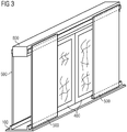
- Figure 3 shows by way of example and schematically an oblique view of a sliding door system according to the invention with integrated into the upper guide rail door drive. It is the door system Fig.2 shown in an oblique view.
Landscapes
- Engineering & Computer Science (AREA)
- Mechanical Engineering (AREA)
- Power-Operated Mechanisms For Wings (AREA)
- Support Devices For Sliding Doors (AREA)
Description
- Die Erfindung betrifft ein Schienenfahrzeuginnenschiebetürsystem gemäß dem in diesem technischen Bereich als bekannt anzusehenden Oberbegriff des Anspruchs 1; Beispiele von Schiebetürsystemen dieser Art mit oder ohne Befestigung an einer unteren Führugsschiene bzw. mit oder ohne Verkleidungen, die das Türblatt abdecken, wenn es sich in geöffneter Stellung befindet, sind in den Vorveröffentlichungen
FR 448 685 A WO 2009/023 083 A1 ,US 6 289 643 B1 undDE 20 2005 001781 U1 angegeben. - Die Erfindung betrifft ebenfalls eine Montagelehre zur Montage eines solchen Schienenfahrzeuginnenschiebetürsystems.
- Innentüren in Schienenfahrzeugen werden verwendet um beispielsweise verschiedene Wagenklassen voneinander abzuteilen oder um einen sogenannten Windfang im Eingangsbereich vom Passagierbereich abzutrennen. Diese Innentüren werden üblicherweise als Schiebetüren ausgeführt, da dieses Konstruktionsprinzip eine optimale Raumausnützung erlaubt. Sehr häufig werden diese Innentüren mit einem elektrischen Antrieb versehen. An Innentüren werden spezifische, zu Außentüren sehr unterschiedliche, Anforderungen gestellt. Neben einer betriebssicheren, einfachen Betätigung muss eine Innentür in Schienenfahrzeugen einen geringen Raumverbrauch aufweisen und sich an die verschiedenen ästhetischen Gestaltungen unterschiedlicher Fahrzeugtypen gut anpassen lassen. Der bei Schiebetüren unvermeidliche Spalt zwischen dem beweglichen Türblatt und einer feststehenden Verkleidung ist als verletzungsträchtige Gefahrenquelle geeignet abzudecken, was auch von den Zulassungsvorschriften für Schienenfahrzeuge gefordert wird. Der Einbau der Innentüren (bestehend aus Türblättern, Verkleidungsteilen, Türantrieb, etc.) in das Schienenfahrzeug erfolgt in einer Weise, dass diese Bauteile mittels sogenannter Konsolen mit dem Wagenkörper verbunden werden. Aufgrund der unvermeidlichen Toleranzen der Wagenkörper sind dabei entsprechende Einstellmöglichkeiten vorzusehen, welche in einem zeitaufwendigen Justageprozeß genutzt werden um die Innentür korrekt einzubauen. Dabei muss besonders auf die Abmessungen des Spalts zwischen dem Türblatt und den Verkleidungsteilen geachtet werden.
- Der Erfindung liegt daher die Aufgabe zugrunde, ein Schiebetürsystem zum Aufbau von Innentüren von Schienenfahrzeugen anzugeben, welches die Nachteile der Türsysteme gemäß dem Stand der Technik vermeidet und welches insbesondere ohne aufwendige Justagearbeiten eingebaut werden kann.
- Die Aufgabe wird durch ein Schienenfahrzeuginnenschiebetürsystem mit den Merkmalen des Anspruchs 1 sowie eine Montagelehre mit den Merkmalen des Anspruchs 4 gelöst. Vorteilhafte Ausgestaltungen sind Gegenstand untergeordneter Ansprüche.
- Dem Grundgedanken der Erfindung nach wird ein Schiebetürsystem aus einer unteren Führungsschiene, einer oberen Führungsschiene und mindestes einem, zwischen diesen Führungsschienen schiebbar gelagerten Türblatt aufgebaut. Verkleidungen decken das Türblatt ab, wenn es sich in geöffneter Stellung befindet. Die untere und die obere Führungsschiene weisen jeweils Positionierungsmittel auf, welche den Verkleidungen die vorgesehene Position vorgeben. Damit ist der Vorteil erzielbar, eine verkleidete Schiebetür ohne Justagearbeiten an den Verkleidungen in ein Schienenfahrzeug einbauen zu können, da die aufwendige Relativpositionierung (beispielsweise mittels Langlöcher oder eingelegten Zwischenstücken) der Verkleidungen komplett entfällt. Die Verkleidungen werden erfindungsgemäß ausschließlich an der oberen und der unteren Führungsschiene befestigt, sodass nur die Relativpositionierung dieser beiden Führungsschienen zueinander erfolgen muss.
- Die Montage des Schiebetürsystems erfolgt in folgender Reihenfolge:
- Montage der unteren Führungsschiene am Wagenkasten,
- Aufsetzen einer Montagelehre an Paßvorrichtungen der unteren Führungsschiene,
- Aufsetzen der oberen Führungsschiene auf Paßvorrichtungen der Montagelehre,
- Befestigen der solcherart positionierten oberen Führungsschiene an den Wagenkasten,
- Entfernen der Montagelehre,
- Einbau des Türblatts, bzw. der Türblätter,
- Montage der Verkleidungen an den Positionierungsmitteln der oberen und unteren Führungsschienen.
- Ganz besonders vorteilhaft ist es, dass der Spalt zwischen einem Türblatt und einer Verkleidung nicht justiert werden muss, da dieser (sicherheitskritische) Spalt mittels der Positionierungsmittel der oberen und unteren Führungsschienen exakt vorgegeben ist.
- Eine besondere Ausführungsform der Erfindung sieht den Einsatz eines (typischerweise elektrischen) Türantriebs vor. Dabei sind die Konstruktion und die Montagereihenfolge des Türsystems gegebenenfalls anzupassen. Dieser Türantrieb kann auch in die obere Führungsschiene integriert sein.
- Eine Montagelehre zur Montage des erfindungsgemäßen Türsystems wird nach der Montage der unteren Führungsschiene auf die Paßstellen (z.B. Bohrungen) formschlüssig aufgesetzt. Diese Montagelehre umfasst Paßvorrichtungen zur Aufnahme der oberen Führungsschiene. Die obere Führungsschiene wird in diese Paßvorrichtungen eingebracht und am Wagenkasten befestigt. Somit ist sichergestellt, dass die relative Position der oberen zur unteren Führungsschiene sich im dafür vorgesehenen Toleranzbereich befindet. Dabei ist es vorteilhaft, dass keine Mess- und Justagearbeiten zum Einrichten dieser Relativposition erforderlich sind. Weiters ist es vorteilhaft, die Montagelehre zerlegbar zu gestalten. Dadurch ist es möglich, die Montagelehre mir sehr geringem personellen Aufwand zu transportieren und insbesondere ist die Montagelehre somit durch die Außentüren eines Schienenfahrzeugs transportierbar.
- Es zeigen beispielhaft:
-
Fig.1 eine Schnittansicht durch ein erfindungsgemäßes Schiebetürsystem. -
Fig.2 eine Schnittansicht durch ein erfindungsgemäßes Schiebetürsystem mit in die obere Führungsschiene integriertem Türantrieb. -
Fig.3 eine Schrägansicht eines erfindungsgemäßen Schiebetürsystems mit in die obere Führungsschiene integriertem Türantrieb. -
Fig.1 zeigt beispielhaft und schematisch eine Schnittansicht durch ein erfindungsgemäßes Schiebetürsystem. Das Türsystem umfasst eine untere Führungsschiene 100, eine obere Führungsschiene 200, einen Türantrieb 300, ein Türblatt 400 und Verkleidungen 500. Die untere Führungsschiene 100 ist lösbar (z.B. mittels einer Schraubverbindung) mit dem Wagenkasten 600 verbunden. Die obere Führungsschiene 200 ist ebenso lösbar mit dem Wagenkasten 600 verbunden. Das Türblatt 400 wird mittels des Türantriebs 300 bewegt. Der Türantrieb 300 (beispielsweise ein elektrischer oder pneumatischer Türantrieb) ist mit der oberen Führungsschiene 200 lösbar verbunden. Zwei Verkleidungen 500 bilden eine taschenförmige Einfassung für das Türblatt, wenn es sich in geöffneter Stellung befindet. Die Verkleidungen 500 sind sowohl mit der oberen Führungsschiene 200 als auch mit der unteren Führungsschiene 100 lösbar verbunden, wobei beide Führungsschienen 100, 200 Positionierungsmittel aufweisen, welche die exakte Position der Verkleidungen 500 vorgeben. InFig. 1 ist als Positionierungsmittel beispielhaft eine Nut-Federverbindung zwischen den Verkleidungen 500 und der unteren Führungsschiene 100 dargestellt, welche zusätzlich mit einer Verschraubung gesichert ist. Die Verbindung der Verkleidungen 500 mit der oberen Führungsschiene 200 ist beispielhaft als Schraubverbindung dargestellt, wobei eine Anlagefläche an der oberen Führungsschiene 200 das Positionierungsmittel darstellt. Die Verkleidungen 500 weisen ausschließlich Verbindungen zu den Führungsschienen 100, 200 auf, es bestehen keine unmittelbaren Verbindungen zu weiteren Bauteilen, insbesondere nicht zum Wagenkasten 600. Das Türblatt 400 wird mittels eines Stegs 700 an der unteren Führungsschiene 100 geführt. -
Fig.2 zeigt beispielhaft und schematisch eine Schnittansicht durch ein erfindungsgemäßes Schiebetürsystem mit in die obere Führungsschiene integriertem Türantrieb. Es ist das Türsystem ausFig.1 dargestellt, wobei die beiden in dem Ausführungsbeispiel gemäßFig.1 einzelnen Bauelemente obere Führungsschiene 200 und Türantrieb 300 zu einem einzelnen Bauteil kombiniert sind. Diese kombinierte Führungsschiene 800 umfasst Befestigungsmittel zur lösbaren Befestigung am Wagenkasten 600 und Positionierungsmittel zur exakten Befestigung der Verkleidungen 500. Weiters umfasst die kombinierte Führungsschiene 800 alle Bauelemente eines Türantriebs 300. -
Fig.3 zeigt beispielhaft und schematisch eine Schrägansicht eines erfindungsgemäßen Schiebetürsystems mit in die obere Führungsschiene integriertem Türantrieb. Es ist das Türsystem ausFig.2 in einer Schrägansicht dargestellt. -
- 100
- untere Führungsschiene
- 200
- obere Führungsschiene
- 300
- Türantrieb
- 400
- Türblatt
- 500
- Verkleidung
- 600
- Wagenkasten
- 700
- Steg
- 800
- Kombinierte Führungsschiene
Claims (5)
- Schienenfahrzeuginnenschiebetürsystem, umfassend eine untere Führungsschiene (100), eine obere Führungsschiene (200) und mindestes einem zwischen den Führungsschienen (100,200) schiebbar gelagerten Türblatt (400), sowohl mit der unteren (100) als auch mit der oberen (200) Führungsschiene lösbar verbundene Verkleidungen (500), welche zwischen der oberen Führungsschiene (200) und der unteren Führungsschiene (100) befestigbar sind und das Türblatt abdecken, wenn es sich in geöffneter Stellung befindet, und eine Montagelehre, dadurch gekennzeichnet, dass die obere Führungsschiene (200) und die untere Führungsschiene (100) jeweils Positionierungsmittel zur exakten Positionierung der Verkleidungen (500) aufweisen, welche (500) ausschließlich an der oberen (200) und der unteren (100) Führungsschiene befestigt sind, und wobei zur Positionierung der Führungsschienen (100, 200) zueinander die Montagelehre an der unteren Führungsschiene (100) an Paßvorrichtungen aufsetzbar ist, wodurch die erforderliche Montageposition der oberen Führungsschiene (200) vorgegeben wird.
- Schienenfahrzeuginnenschiebetürsystem gemäß Anspruch 1, dadurch gekennzeichnet, dass
ein Türantrieb (300) vorgesehen ist. - Schienenfahrzeuginnenschiebetürsystem gemäß Anspruch 2, dadurch gekennzeichnet, dass
eine, die Funktionalitäten der oberen Führungsschiene (200) und des Türantriebs (300)umfassende kombinierte Führungsschiene (800) vorgesehen ist. - Montagelehre zur Montage eines
Schienenfahrzeuginnenschiebetürsystem gemäß einem der Ansprüche 1 oder 2, welche auf die am Wagenkasten (600) befestigte untere Führungsschiene (100) an Paßvorrichtungen aufgesetzt wird, wobei die Montagelehre die erforderliche Montageposition der oberen Führungsschiene (200) angibt. - Montagelehre gemäß Anspruch 4, dadurch gekennzeichnet, dass die Montagelehre zerlegbar ausgeführt ist.
Applications Claiming Priority (2)
| Application Number | Priority Date | Filing Date | Title |
|---|---|---|---|
| AT0072509A AT508122B1 (de) | 2009-05-12 | 2009-05-12 | Schiebetürsystem für schienenfahrzeuge |
| PCT/EP2010/055247 WO2010130537A1 (de) | 2009-05-12 | 2010-04-21 | Schiebetürsystem für schienenfahrzeuge |
Publications (2)
| Publication Number | Publication Date |
|---|---|
| EP2430276A1 EP2430276A1 (de) | 2012-03-21 |
| EP2430276B1 true EP2430276B1 (de) | 2018-04-18 |
Family
ID=42320970
Family Applications (1)
| Application Number | Title | Priority Date | Filing Date |
|---|---|---|---|
| EP10718922.7A Active EP2430276B1 (de) | 2009-05-12 | 2010-04-21 | Schiebetürsystem für schienenfahrzeuge |
Country Status (5)
| Country | Link |
|---|---|
| EP (1) | EP2430276B1 (de) |
| AT (1) | AT508122B1 (de) |
| ES (1) | ES2678471T3 (de) |
| HU (1) | HUE038491T2 (de) |
| WO (1) | WO2010130537A1 (de) |
Families Citing this family (5)
| Publication number | Priority date | Publication date | Assignee | Title |
|---|---|---|---|---|
| AT12515U1 (de) * | 2011-05-12 | 2012-06-15 | Siemens Ag Oesterreich | Schienenfahrzeuginnentür |
| DE102011087212A1 (de) * | 2011-11-28 | 2013-05-29 | Siemens Aktiengesellschaft | Wagenkasten eines Schienenfahrzeugs mit verfahrbarer Abtrennungstür |
| JP6221174B2 (ja) * | 2013-11-14 | 2017-11-01 | 三菱重工業株式会社 | 車両用引戸装置、および車両用引戸装置を備える車両 |
| SK8832Y1 (sk) | 2019-02-07 | 2020-08-03 | Tatravagonka As | Horný mechanizmus otvárania posuvnej steny alebo bočnice |
| EP4126626B1 (de) | 2020-05-28 | 2024-04-03 | Siemens Mobility GmbH | Doppelflügelige türvorrichtung für ein fahrzeug |
Family Cites Families (4)
| Publication number | Priority date | Publication date | Assignee | Title |
|---|---|---|---|---|
| FR448685A (fr) * | 1912-09-26 | 1913-02-07 | Compagnie Belge Des Machines A Cigarettes Et De Co | Nouveau dispositif mécanique équilibré de guidage et fermeture des portes coulissantes en général |
| US6289643B1 (en) * | 1999-09-07 | 2001-09-18 | Autoglide, Inc. | Residential motorized sliding door assembly |
| DE202005001781U1 (de) * | 2005-02-03 | 2005-04-07 | Dorma Gmbh & Co Kg | Gehäuse für automatische Türantriebe |
| US8020346B2 (en) * | 2007-08-16 | 2011-09-20 | Joseph Singiser | Magnetically supported sliding track system |
-
2009
- 2009-05-12 AT AT0072509A patent/AT508122B1/de not_active IP Right Cessation
-
2010
- 2010-04-21 EP EP10718922.7A patent/EP2430276B1/de active Active
- 2010-04-21 WO PCT/EP2010/055247 patent/WO2010130537A1/de not_active Ceased
- 2010-04-21 HU HUE10718922A patent/HUE038491T2/hu unknown
- 2010-04-21 ES ES10718922.7T patent/ES2678471T3/es active Active
Non-Patent Citations (1)
| Title |
|---|
| None * |
Also Published As
| Publication number | Publication date |
|---|---|
| AT508122A4 (de) | 2010-11-15 |
| WO2010130537A1 (de) | 2010-11-18 |
| EP2430276A1 (de) | 2012-03-21 |
| ES2678471T3 (es) | 2018-08-13 |
| AT508122B1 (de) | 2010-11-15 |
| HUE038491T2 (hu) | 2018-10-29 |
Similar Documents
| Publication | Publication Date | Title |
|---|---|---|
| AT508122B1 (de) | Schiebetürsystem für schienenfahrzeuge | |
| DE102008064548B4 (de) | Rahmenvorrichtung eines Fahrzeugdaches mit einer Antriebseinheit | |
| EP3140174B1 (de) | Fahrzeug, insbesondere schienenfahrzeug, mit einer montageschiene | |
| DE19717906B4 (de) | Vorrichtung zur Montage eines Kraftfahrzeugtürschlosses | |
| EP3212483B1 (de) | Einrichtung zur vertikalen einstellung einer schienenfahrzeugtür | |
| AT520638B1 (de) | Befestigung für Innenausbauteile von Fahrzeugen | |
| DE102011013085A1 (de) | Vorrichtung zum Bewegen eines Flügels eines Fensters, einer Tür oder dergleichen | |
| DE102008020081B4 (de) | Schweller | |
| DE102009031541A1 (de) | Befestigungsanordnung eines Verkleidungsteils für einen Innenraum eines Kraftwagens an einem tragenden Bauteil | |
| EP1313929B1 (de) | Türbefestigung | |
| DE202014103236U1 (de) | Befestigen von Verkleidungsteilen an einer Unterkonstruktion | |
| DE102010043821A1 (de) | Verriegelungseinrichtung für ein Seitensektionaltor | |
| EP3850175B1 (de) | Einrichtung zur justierung eines türantriebs | |
| EP2026436A2 (de) | Isolierprofil | |
| EP2754817A2 (de) | Befestigungsplatte | |
| DE102015221572B4 (de) | Antriebseinrichtung für ein Gurtschloss einer Sicherheitsgurteinrichtung | |
| EP3116766A1 (de) | Baugruppe für ein kraftfahrzeug und verfahren zum verbinden eines karosserieteils mit einem spoiler | |
| EP3771608B1 (de) | Personentransportmittel mit einer vorrichtung zum verschieben mindestens eines elektrischen kontakts | |
| DE202008004517U1 (de) | Zustiegshilfe mit verbessertem Spindelantrieb | |
| DE19859671C1 (de) | Scharnierverbindung für einen Behälter einer Atemgasversorgungseinheit in einem Flugzeug | |
| DE102016111168A1 (de) | Antriebsvorrichtung für eine Verschattungseinrichtung | |
| EP2966307A1 (de) | Anordnung und verfahren zum befestigen von verkleidungsteilen an einer unterkonstruktion | |
| DE202006017488U1 (de) | Ein-/Ausstiegsvorrichtung für ein Fahrzeug des öffentlichen Personenverkehrs mit einem in einem Rahmen angeordneten Schiebetritt | |
| EP2767667A1 (de) | Rollosystem zum manuellen Auf- und Abwickeln eines Rollos | |
| DE102013215074B4 (de) | Befestigungsvorrichtung für längliche Gegenstände sowie Befestigungssystem |
Legal Events
| Date | Code | Title | Description |
|---|---|---|---|
| PUAI | Public reference made under article 153(3) epc to a published international application that has entered the european phase |
Free format text: ORIGINAL CODE: 0009012 |
|
| 17P | Request for examination filed |
Effective date: 20110909 |
|
| AK | Designated contracting states |
Kind code of ref document: A1 Designated state(s): AT BE BG CH CY CZ DE DK EE ES FI FR GB GR HR HU IE IS IT LI LT LU LV MC MK MT NL NO PL PT RO SE SI SK SM TR |
|
| DAX | Request for extension of the european patent (deleted) | ||
| REG | Reference to a national code |
Ref country code: DE Ref legal event code: R079 Ref document number: 502010014882 Country of ref document: DE Free format text: PREVIOUS MAIN CLASS: E05F0015140000 Ipc: B61D0019000000 |
|
| GRAP | Despatch of communication of intention to grant a patent |
Free format text: ORIGINAL CODE: EPIDOSNIGR1 |
|
| STAA | Information on the status of an ep patent application or granted ep patent |
Free format text: STATUS: GRANT OF PATENT IS INTENDED |
|
| RIC1 | Information provided on ipc code assigned before grant |
Ipc: E05F 15/00 20150101ALI20171009BHEP Ipc: B61D 19/00 20060101AFI20171009BHEP Ipc: B61D 19/02 20060101ALI20171009BHEP Ipc: E05D 15/06 20060101ALI20171009BHEP |
|
| INTG | Intention to grant announced |
Effective date: 20171115 |
|
| GRAS | Grant fee paid |
Free format text: ORIGINAL CODE: EPIDOSNIGR3 |
|
| GRAA | (expected) grant |
Free format text: ORIGINAL CODE: 0009210 |
|
| STAA | Information on the status of an ep patent application or granted ep patent |
Free format text: STATUS: THE PATENT HAS BEEN GRANTED |
|
| AK | Designated contracting states |
Kind code of ref document: B1 Designated state(s): AT BE BG CH CY CZ DE DK EE ES FI FR GB GR HR HU IE IS IT LI LT LU LV MC MK MT NL NO PL PT RO SE SI SK SM TR |
|
| REG | Reference to a national code |
Ref country code: GB Ref legal event code: FG4D Free format text: NOT ENGLISH |
|
| REG | Reference to a national code |
Ref country code: CH Ref legal event code: EP |
|
| REG | Reference to a national code |
Ref country code: DE Ref legal event code: R096 Ref document number: 502010014882 Country of ref document: DE |
|
| REG | Reference to a national code |
Ref country code: AT Ref legal event code: REF Ref document number: 990108 Country of ref document: AT Kind code of ref document: T Effective date: 20180515 |
|
| REG | Reference to a national code |
Ref country code: IE Ref legal event code: FG4D Free format text: LANGUAGE OF EP DOCUMENT: GERMAN |
|
| REG | Reference to a national code |
Ref country code: CH Ref legal event code: NV Representative=s name: SIEMENS SCHWEIZ AG, CH |
|
| REG | Reference to a national code |
Ref country code: FR Ref legal event code: PLFP Year of fee payment: 9 |
|
| REG | Reference to a national code |
Ref country code: ES Ref legal event code: FG2A Ref document number: 2678471 Country of ref document: ES Kind code of ref document: T3 Effective date: 20180813 |
|
| REG | Reference to a national code |
Ref country code: NL Ref legal event code: MP Effective date: 20180418 |
|
| REG | Reference to a national code |
Ref country code: LT Ref legal event code: MG4D |
|
| PG25 | Lapsed in a contracting state [announced via postgrant information from national office to epo] |
Ref country code: NL Free format text: LAPSE BECAUSE OF FAILURE TO SUBMIT A TRANSLATION OF THE DESCRIPTION OR TO PAY THE FEE WITHIN THE PRESCRIBED TIME-LIMIT Effective date: 20180418 |
|
| REG | Reference to a national code |
Ref country code: HU Ref legal event code: AG4A Ref document number: E038491 Country of ref document: HU |
|
| PG25 | Lapsed in a contracting state [announced via postgrant information from national office to epo] |
Ref country code: SE Free format text: LAPSE BECAUSE OF FAILURE TO SUBMIT A TRANSLATION OF THE DESCRIPTION OR TO PAY THE FEE WITHIN THE PRESCRIBED TIME-LIMIT Effective date: 20180418 Ref country code: LT Free format text: LAPSE BECAUSE OF FAILURE TO SUBMIT A TRANSLATION OF THE DESCRIPTION OR TO PAY THE FEE WITHIN THE PRESCRIBED TIME-LIMIT Effective date: 20180418 Ref country code: PL Free format text: LAPSE BECAUSE OF FAILURE TO SUBMIT A TRANSLATION OF THE DESCRIPTION OR TO PAY THE FEE WITHIN THE PRESCRIBED TIME-LIMIT Effective date: 20180418 Ref country code: BG Free format text: LAPSE BECAUSE OF FAILURE TO SUBMIT A TRANSLATION OF THE DESCRIPTION OR TO PAY THE FEE WITHIN THE PRESCRIBED TIME-LIMIT Effective date: 20180718 Ref country code: FI Free format text: LAPSE BECAUSE OF FAILURE TO SUBMIT A TRANSLATION OF THE DESCRIPTION OR TO PAY THE FEE WITHIN THE PRESCRIBED TIME-LIMIT Effective date: 20180418 Ref country code: NO Free format text: LAPSE BECAUSE OF FAILURE TO SUBMIT A TRANSLATION OF THE DESCRIPTION OR TO PAY THE FEE WITHIN THE PRESCRIBED TIME-LIMIT Effective date: 20180718 |
|
| PG25 | Lapsed in a contracting state [announced via postgrant information from national office to epo] |
Ref country code: GR Free format text: LAPSE BECAUSE OF FAILURE TO SUBMIT A TRANSLATION OF THE DESCRIPTION OR TO PAY THE FEE WITHIN THE PRESCRIBED TIME-LIMIT Effective date: 20180719 Ref country code: LV Free format text: LAPSE BECAUSE OF FAILURE TO SUBMIT A TRANSLATION OF THE DESCRIPTION OR TO PAY THE FEE WITHIN THE PRESCRIBED TIME-LIMIT Effective date: 20180418 Ref country code: HR Free format text: LAPSE BECAUSE OF FAILURE TO SUBMIT A TRANSLATION OF THE DESCRIPTION OR TO PAY THE FEE WITHIN THE PRESCRIBED TIME-LIMIT Effective date: 20180418 |
|
| REG | Reference to a national code |
Ref country code: BE Ref legal event code: MM Effective date: 20180430 |
|
| PG25 | Lapsed in a contracting state [announced via postgrant information from national office to epo] |
Ref country code: PT Free format text: LAPSE BECAUSE OF FAILURE TO SUBMIT A TRANSLATION OF THE DESCRIPTION OR TO PAY THE FEE WITHIN THE PRESCRIBED TIME-LIMIT Effective date: 20180820 |
|
| REG | Reference to a national code |
Ref country code: DE Ref legal event code: R097 Ref document number: 502010014882 Country of ref document: DE |
|
| REG | Reference to a national code |
Ref country code: IE Ref legal event code: MM4A |
|
| PG25 | Lapsed in a contracting state [announced via postgrant information from national office to epo] |
Ref country code: MC Free format text: LAPSE BECAUSE OF FAILURE TO SUBMIT A TRANSLATION OF THE DESCRIPTION OR TO PAY THE FEE WITHIN THE PRESCRIBED TIME-LIMIT Effective date: 20180418 Ref country code: SK Free format text: LAPSE BECAUSE OF FAILURE TO SUBMIT A TRANSLATION OF THE DESCRIPTION OR TO PAY THE FEE WITHIN THE PRESCRIBED TIME-LIMIT Effective date: 20180418 Ref country code: LU Free format text: LAPSE BECAUSE OF NON-PAYMENT OF DUE FEES Effective date: 20180421 Ref country code: RO Free format text: LAPSE BECAUSE OF FAILURE TO SUBMIT A TRANSLATION OF THE DESCRIPTION OR TO PAY THE FEE WITHIN THE PRESCRIBED TIME-LIMIT Effective date: 20180418 Ref country code: DK Free format text: LAPSE BECAUSE OF FAILURE TO SUBMIT A TRANSLATION OF THE DESCRIPTION OR TO PAY THE FEE WITHIN THE PRESCRIBED TIME-LIMIT Effective date: 20180418 Ref country code: EE Free format text: LAPSE BECAUSE OF FAILURE TO SUBMIT A TRANSLATION OF THE DESCRIPTION OR TO PAY THE FEE WITHIN THE PRESCRIBED TIME-LIMIT Effective date: 20180418 |
|
| PLBE | No opposition filed within time limit |
Free format text: ORIGINAL CODE: 0009261 |
|
| STAA | Information on the status of an ep patent application or granted ep patent |
Free format text: STATUS: NO OPPOSITION FILED WITHIN TIME LIMIT |
|
| PG25 | Lapsed in a contracting state [announced via postgrant information from national office to epo] |
Ref country code: BE Free format text: LAPSE BECAUSE OF NON-PAYMENT OF DUE FEES Effective date: 20180430 Ref country code: SM Free format text: LAPSE BECAUSE OF FAILURE TO SUBMIT A TRANSLATION OF THE DESCRIPTION OR TO PAY THE FEE WITHIN THE PRESCRIBED TIME-LIMIT Effective date: 20180418 |
|
| 26N | No opposition filed |
Effective date: 20190121 |
|
| GBPC | Gb: european patent ceased through non-payment of renewal fee |
Effective date: 20180718 |
|
| REG | Reference to a national code |
Ref country code: CH Ref legal event code: PUE Owner name: SIEMENS MOBILITY GMBH, AT Free format text: FORMER OWNER: SIEMENS AG OESTERREICH, AT |
|
| PG25 | Lapsed in a contracting state [announced via postgrant information from national office to epo] |
Ref country code: IE Free format text: LAPSE BECAUSE OF NON-PAYMENT OF DUE FEES Effective date: 20180421 Ref country code: GB Free format text: LAPSE BECAUSE OF NON-PAYMENT OF DUE FEES Effective date: 20180718 |
|
| REG | Reference to a national code |
Ref country code: DE Ref legal event code: R082 Ref document number: 502010014882 Country of ref document: DE Representative=s name: DEFFNER, ROLF, DR., DE Ref country code: DE Ref legal event code: R081 Ref document number: 502010014882 Country of ref document: DE Owner name: SIEMENS MOBILITY GMBH, AT Free format text: FORMER OWNER: SIEMENS AKTIENGESELLSCHAFT OESTERREICH, WIEN, AT Ref country code: DE Ref legal event code: R081 Ref document number: 502010014882 Country of ref document: DE Owner name: SIEMENS MOBILITY AUSTRIA GMBH, AT Free format text: FORMER OWNER: SIEMENS AKTIENGESELLSCHAFT OESTERREICH, WIEN, AT |
|
| PG25 | Lapsed in a contracting state [announced via postgrant information from national office to epo] |
Ref country code: SI Free format text: LAPSE BECAUSE OF FAILURE TO SUBMIT A TRANSLATION OF THE DESCRIPTION OR TO PAY THE FEE WITHIN THE PRESCRIBED TIME-LIMIT Effective date: 20180418 |
|
| REG | Reference to a national code |
Ref country code: AT Ref legal event code: PC Ref document number: 990108 Country of ref document: AT Kind code of ref document: T Owner name: SIEMENS MOBILITY GMBH, AT Effective date: 20190814 |
|
| REG | Reference to a national code |
Ref country code: DE Ref legal event code: R082 Ref document number: 502010014882 Country of ref document: DE Representative=s name: DEFFNER, ROLF, DR., DE Ref country code: DE Ref legal event code: R081 Ref document number: 502010014882 Country of ref document: DE Owner name: SIEMENS MOBILITY AUSTRIA GMBH, AT Free format text: FORMER OWNER: SIEMENS MOBILITY GMBH, WIEN, AT |
|
| REG | Reference to a national code |
Ref country code: CH Ref legal event code: PFA Owner name: SIEMENS MOBILITY AUSTRIA GMBH, AT Free format text: FORMER OWNER: SIEMENS MOBILITY GMBH, AT |
|
| PG25 | Lapsed in a contracting state [announced via postgrant information from national office to epo] |
Ref country code: MT Free format text: LAPSE BECAUSE OF FAILURE TO SUBMIT A TRANSLATION OF THE DESCRIPTION OR TO PAY THE FEE WITHIN THE PRESCRIBED TIME-LIMIT Effective date: 20180418 |
|
| REG | Reference to a national code |
Ref country code: HU Ref legal event code: FH1C Free format text: FORMER REPRESENTATIVE(S): SBGK SZABADALMI UEGYVIVOEI IRODA, HU Representative=s name: SBGK SZABADALMI UEGYVIVOEI IRODA, HU Ref country code: HU Ref legal event code: GB9C Owner name: SIEMENS MOBILITY AUSTRIA GMBH, AT Free format text: FORMER OWNER(S): SIEMENS AG OESTERREICH, AT |
|
| PG25 | Lapsed in a contracting state [announced via postgrant information from national office to epo] |
Ref country code: TR Free format text: LAPSE BECAUSE OF FAILURE TO SUBMIT A TRANSLATION OF THE DESCRIPTION OR TO PAY THE FEE WITHIN THE PRESCRIBED TIME-LIMIT Effective date: 20180418 |
|
| REG | Reference to a national code |
Ref country code: ES Ref legal event code: PC2A Owner name: SIEMENS MOBILITY AUSTRIA GMBH Effective date: 20200414 |
|
| PG25 | Lapsed in a contracting state [announced via postgrant information from national office to epo] |
Ref country code: CY Free format text: LAPSE BECAUSE OF FAILURE TO SUBMIT A TRANSLATION OF THE DESCRIPTION OR TO PAY THE FEE WITHIN THE PRESCRIBED TIME-LIMIT Effective date: 20180418 Ref country code: MK Free format text: LAPSE BECAUSE OF NON-PAYMENT OF DUE FEES Effective date: 20180418 |
|
| PG25 | Lapsed in a contracting state [announced via postgrant information from national office to epo] |
Ref country code: IS Free format text: LAPSE BECAUSE OF FAILURE TO SUBMIT A TRANSLATION OF THE DESCRIPTION OR TO PAY THE FEE WITHIN THE PRESCRIBED TIME-LIMIT Effective date: 20180818 |
|
| REG | Reference to a national code |
Ref country code: AT Ref legal event code: HC Ref document number: 990108 Country of ref document: AT Kind code of ref document: T Owner name: SIEMENS MOBILITY AUSTRIA GMBH, AT Effective date: 20211108 |
|
| PGFP | Annual fee paid to national office [announced via postgrant information from national office to epo] |
Ref country code: DE Payment date: 20250620 Year of fee payment: 16 |
|
| PGFP | Annual fee paid to national office [announced via postgrant information from national office to epo] |
Ref country code: IT Payment date: 20250417 Year of fee payment: 16 |
|
| PGFP | Annual fee paid to national office [announced via postgrant information from national office to epo] |
Ref country code: FR Payment date: 20250411 Year of fee payment: 16 Ref country code: HU Payment date: 20250620 Year of fee payment: 16 |
|
| PGFP | Annual fee paid to national office [announced via postgrant information from national office to epo] |
Ref country code: AT Payment date: 20250307 Year of fee payment: 16 |
|
| PGFP | Annual fee paid to national office [announced via postgrant information from national office to epo] |
Ref country code: CZ Payment date: 20250414 Year of fee payment: 16 |
|
| PGFP | Annual fee paid to national office [announced via postgrant information from national office to epo] |
Ref country code: ES Payment date: 20250721 Year of fee payment: 16 |
|
| PGFP | Annual fee paid to national office [announced via postgrant information from national office to epo] |
Ref country code: CH Payment date: 20250709 Year of fee payment: 16 |