EP2428740B1 - Klimaanlage und Betriebsverfahren dafür - Google Patents
Klimaanlage und Betriebsverfahren dafür Download PDFInfo
- Publication number
- EP2428740B1 EP2428740B1 EP11179673.6A EP11179673A EP2428740B1 EP 2428740 B1 EP2428740 B1 EP 2428740B1 EP 11179673 A EP11179673 A EP 11179673A EP 2428740 B1 EP2428740 B1 EP 2428740B1
- Authority
- EP
- European Patent Office
- Prior art keywords
- hot water
- refrigerant
- indoor units
- expansion valve
- indoor
- Prior art date
- Legal status (The legal status is an assumption and is not a legal conclusion. Google has not performed a legal analysis and makes no representation as to the accuracy of the status listed.)
- Active
Links
Images

Classifications
-
- F—MECHANICAL ENGINEERING; LIGHTING; HEATING; WEAPONS; BLASTING
- F24—HEATING; RANGES; VENTILATING
- F24D—DOMESTIC- OR SPACE-HEATING SYSTEMS, e.g. CENTRAL HEATING SYSTEMS; DOMESTIC HOT-WATER SUPPLY SYSTEMS; ELEMENTS OR COMPONENTS THEREFOR
- F24D11/00—Central heating systems using heat accumulated in storage masses
- F24D11/02—Central heating systems using heat accumulated in storage masses using heat pumps
- F24D11/0214—Central heating systems using heat accumulated in storage masses using heat pumps water heating system
-
- F—MECHANICAL ENGINEERING; LIGHTING; HEATING; WEAPONS; BLASTING
- F24—HEATING; RANGES; VENTILATING
- F24D—DOMESTIC- OR SPACE-HEATING SYSTEMS, e.g. CENTRAL HEATING SYSTEMS; DOMESTIC HOT-WATER SUPPLY SYSTEMS; ELEMENTS OR COMPONENTS THEREFOR
- F24D15/00—Other domestic- or space-heating systems
- F24D15/04—Other domestic- or space-heating systems using heat pumps
-
- F—MECHANICAL ENGINEERING; LIGHTING; HEATING; WEAPONS; BLASTING
- F24—HEATING; RANGES; VENTILATING
- F24D—DOMESTIC- OR SPACE-HEATING SYSTEMS, e.g. CENTRAL HEATING SYSTEMS; DOMESTIC HOT-WATER SUPPLY SYSTEMS; ELEMENTS OR COMPONENTS THEREFOR
- F24D17/00—Domestic hot-water supply systems
- F24D17/02—Domestic hot-water supply systems using heat pumps
-
- F—MECHANICAL ENGINEERING; LIGHTING; HEATING; WEAPONS; BLASTING
- F24—HEATING; RANGES; VENTILATING
- F24D—DOMESTIC- OR SPACE-HEATING SYSTEMS, e.g. CENTRAL HEATING SYSTEMS; DOMESTIC HOT-WATER SUPPLY SYSTEMS; ELEMENTS OR COMPONENTS THEREFOR
- F24D19/00—Details
- F24D19/10—Arrangement or mounting of control or safety devices
- F24D19/1006—Arrangement or mounting of control or safety devices for water heating systems
- F24D19/1009—Arrangement or mounting of control or safety devices for water heating systems for central heating
- F24D19/1039—Arrangement or mounting of control or safety devices for water heating systems for central heating the system uses a heat pump
-
- F—MECHANICAL ENGINEERING; LIGHTING; HEATING; WEAPONS; BLASTING
- F24—HEATING; RANGES; VENTILATING
- F24D—DOMESTIC- OR SPACE-HEATING SYSTEMS, e.g. CENTRAL HEATING SYSTEMS; DOMESTIC HOT-WATER SUPPLY SYSTEMS; ELEMENTS OR COMPONENTS THEREFOR
- F24D19/00—Details
- F24D19/10—Arrangement or mounting of control or safety devices
- F24D19/1006—Arrangement or mounting of control or safety devices for water heating systems
- F24D19/1051—Arrangement or mounting of control or safety devices for water heating systems for domestic hot water
- F24D19/1054—Arrangement or mounting of control or safety devices for water heating systems for domestic hot water the system uses a heat pump
-
- F—MECHANICAL ENGINEERING; LIGHTING; HEATING; WEAPONS; BLASTING
- F24—HEATING; RANGES; VENTILATING
- F24D—DOMESTIC- OR SPACE-HEATING SYSTEMS, e.g. CENTRAL HEATING SYSTEMS; DOMESTIC HOT-WATER SUPPLY SYSTEMS; ELEMENTS OR COMPONENTS THEREFOR
- F24D19/00—Details
- F24D19/10—Arrangement or mounting of control or safety devices
- F24D19/1084—Arrangement or mounting of control or safety devices for air heating systems
- F24D19/1087—Arrangement or mounting of control or safety devices for air heating systems system using a heat pump
-
- F—MECHANICAL ENGINEERING; LIGHTING; HEATING; WEAPONS; BLASTING
- F24—HEATING; RANGES; VENTILATING
- F24D—DOMESTIC- OR SPACE-HEATING SYSTEMS, e.g. CENTRAL HEATING SYSTEMS; DOMESTIC HOT-WATER SUPPLY SYSTEMS; ELEMENTS OR COMPONENTS THEREFOR
- F24D3/00—Hot-water central heating systems
- F24D3/08—Hot-water central heating systems in combination with systems for domestic hot-water supply
-
- F—MECHANICAL ENGINEERING; LIGHTING; HEATING; WEAPONS; BLASTING
- F24—HEATING; RANGES; VENTILATING
- F24F—AIR-CONDITIONING; AIR-HUMIDIFICATION; VENTILATION; USE OF AIR CURRENTS FOR SCREENING
- F24F11/00—Control or safety arrangements
- F24F11/70—Control systems characterised by their outputs; Constructional details thereof
- F24F11/80—Control systems characterised by their outputs; Constructional details thereof for controlling the temperature of the supplied air
- F24F11/83—Control systems characterised by their outputs; Constructional details thereof for controlling the temperature of the supplied air by controlling the supply of heat-exchange fluids to heat-exchangers
- F24F11/84—Control systems characterised by their outputs; Constructional details thereof for controlling the temperature of the supplied air by controlling the supply of heat-exchange fluids to heat-exchangers using valves
-
- F—MECHANICAL ENGINEERING; LIGHTING; HEATING; WEAPONS; BLASTING
- F24—HEATING; RANGES; VENTILATING
- F24F—AIR-CONDITIONING; AIR-HUMIDIFICATION; VENTILATION; USE OF AIR CURRENTS FOR SCREENING
- F24F3/00—Air-conditioning systems in which conditioned primary air is supplied from one or more central stations to distributing units in the rooms or spaces where it may receive secondary treatment; Apparatus specially designed for such systems
- F24F3/06—Air-conditioning systems in which conditioned primary air is supplied from one or more central stations to distributing units in the rooms or spaces where it may receive secondary treatment; Apparatus specially designed for such systems characterised by the arrangements for the supply of heat-exchange fluid for the subsequent treatment of primary air in the room units
- F24F3/065—Air-conditioning systems in which conditioned primary air is supplied from one or more central stations to distributing units in the rooms or spaces where it may receive secondary treatment; Apparatus specially designed for such systems characterised by the arrangements for the supply of heat-exchange fluid for the subsequent treatment of primary air in the room units with a plurality of evaporators or condensers
-
- F—MECHANICAL ENGINEERING; LIGHTING; HEATING; WEAPONS; BLASTING
- F24—HEATING; RANGES; VENTILATING
- F24H—FLUID HEATERS, e.g. WATER OR AIR HEATERS, HAVING HEAT-GENERATING MEANS, e.g. HEAT PUMPS, IN GENERAL
- F24H15/00—Control of fluid heaters
- F24H15/20—Control of fluid heaters characterised by control inputs
- F24H15/212—Temperature of the water
- F24H15/219—Temperature of the water after heating
-
- F—MECHANICAL ENGINEERING; LIGHTING; HEATING; WEAPONS; BLASTING
- F24—HEATING; RANGES; VENTILATING
- F24H—FLUID HEATERS, e.g. WATER OR AIR HEATERS, HAVING HEAT-GENERATING MEANS, e.g. HEAT PUMPS, IN GENERAL
- F24H15/00—Control of fluid heaters
- F24H15/20—Control of fluid heaters characterised by control inputs
- F24H15/242—Pressure
-
- F—MECHANICAL ENGINEERING; LIGHTING; HEATING; WEAPONS; BLASTING
- F24—HEATING; RANGES; VENTILATING
- F24H—FLUID HEATERS, e.g. WATER OR AIR HEATERS, HAVING HEAT-GENERATING MEANS, e.g. HEAT PUMPS, IN GENERAL
- F24H15/00—Control of fluid heaters
- F24H15/30—Control of fluid heaters characterised by control outputs; characterised by the components to be controlled
- F24H15/375—Control of heat pumps
- F24H15/38—Control of compressors of heat pumps
-
- F—MECHANICAL ENGINEERING; LIGHTING; HEATING; WEAPONS; BLASTING
- F24—HEATING; RANGES; VENTILATING
- F24H—FLUID HEATERS, e.g. WATER OR AIR HEATERS, HAVING HEAT-GENERATING MEANS, e.g. HEAT PUMPS, IN GENERAL
- F24H15/00—Control of fluid heaters
- F24H15/30—Control of fluid heaters characterised by control outputs; characterised by the components to be controlled
- F24H15/375—Control of heat pumps
- F24H15/385—Control of expansion valves of heat pumps
-
- F—MECHANICAL ENGINEERING; LIGHTING; HEATING; WEAPONS; BLASTING
- F24—HEATING; RANGES; VENTILATING
- F24H—FLUID HEATERS, e.g. WATER OR AIR HEATERS, HAVING HEAT-GENERATING MEANS, e.g. HEAT PUMPS, IN GENERAL
- F24H6/00—Combined water and air heaters
-
- F—MECHANICAL ENGINEERING; LIGHTING; HEATING; WEAPONS; BLASTING
- F25—REFRIGERATION OR COOLING; COMBINED HEATING AND REFRIGERATION SYSTEMS; HEAT PUMP SYSTEMS; MANUFACTURE OR STORAGE OF ICE; LIQUEFACTION SOLIDIFICATION OF GASES
- F25B—REFRIGERATION MACHINES, PLANTS OR SYSTEMS; COMBINED HEATING AND REFRIGERATION SYSTEMS; HEAT PUMP SYSTEMS
- F25B13/00—Compression machines, plants or systems, with reversible cycle
-
- F—MECHANICAL ENGINEERING; LIGHTING; HEATING; WEAPONS; BLASTING
- F24—HEATING; RANGES; VENTILATING
- F24D—DOMESTIC- OR SPACE-HEATING SYSTEMS, e.g. CENTRAL HEATING SYSTEMS; DOMESTIC HOT-WATER SUPPLY SYSTEMS; ELEMENTS OR COMPONENTS THEREFOR
- F24D2200/00—Heat sources or energy sources
- F24D2200/12—Heat pump
- F24D2200/123—Compression type heat pumps
-
- F—MECHANICAL ENGINEERING; LIGHTING; HEATING; WEAPONS; BLASTING
- F25—REFRIGERATION OR COOLING; COMBINED HEATING AND REFRIGERATION SYSTEMS; HEAT PUMP SYSTEMS; MANUFACTURE OR STORAGE OF ICE; LIQUEFACTION SOLIDIFICATION OF GASES
- F25B—REFRIGERATION MACHINES, PLANTS OR SYSTEMS; COMBINED HEATING AND REFRIGERATION SYSTEMS; HEAT PUMP SYSTEMS
- F25B2313/00—Compression machines, plants or systems with reversible cycle not otherwise provided for
- F25B2313/003—Indoor unit with water as a heat sink or heat source
-
- F—MECHANICAL ENGINEERING; LIGHTING; HEATING; WEAPONS; BLASTING
- F25—REFRIGERATION OR COOLING; COMBINED HEATING AND REFRIGERATION SYSTEMS; HEAT PUMP SYSTEMS; MANUFACTURE OR STORAGE OF ICE; LIQUEFACTION SOLIDIFICATION OF GASES
- F25B—REFRIGERATION MACHINES, PLANTS OR SYSTEMS; COMBINED HEATING AND REFRIGERATION SYSTEMS; HEAT PUMP SYSTEMS
- F25B2313/00—Compression machines, plants or systems with reversible cycle not otherwise provided for
- F25B2313/023—Compression machines, plants or systems with reversible cycle not otherwise provided for using multiple indoor units
- F25B2313/0231—Compression machines, plants or systems with reversible cycle not otherwise provided for using multiple indoor units with simultaneous cooling and heating
-
- F—MECHANICAL ENGINEERING; LIGHTING; HEATING; WEAPONS; BLASTING
- F25—REFRIGERATION OR COOLING; COMBINED HEATING AND REFRIGERATION SYSTEMS; HEAT PUMP SYSTEMS; MANUFACTURE OR STORAGE OF ICE; LIQUEFACTION SOLIDIFICATION OF GASES
- F25B—REFRIGERATION MACHINES, PLANTS OR SYSTEMS; COMBINED HEATING AND REFRIGERATION SYSTEMS; HEAT PUMP SYSTEMS
- F25B2313/00—Compression machines, plants or systems with reversible cycle not otherwise provided for
- F25B2313/031—Sensor arrangements
- F25B2313/0314—Temperature sensors near the indoor heat exchanger
-
- F—MECHANICAL ENGINEERING; LIGHTING; HEATING; WEAPONS; BLASTING
- F25—REFRIGERATION OR COOLING; COMBINED HEATING AND REFRIGERATION SYSTEMS; HEAT PUMP SYSTEMS; MANUFACTURE OR STORAGE OF ICE; LIQUEFACTION SOLIDIFICATION OF GASES
- F25B—REFRIGERATION MACHINES, PLANTS OR SYSTEMS; COMBINED HEATING AND REFRIGERATION SYSTEMS; HEAT PUMP SYSTEMS
- F25B2600/00—Control issues
- F25B2600/25—Control of valves
- F25B2600/2513—Expansion valves
-
- F—MECHANICAL ENGINEERING; LIGHTING; HEATING; WEAPONS; BLASTING
- F25—REFRIGERATION OR COOLING; COMBINED HEATING AND REFRIGERATION SYSTEMS; HEAT PUMP SYSTEMS; MANUFACTURE OR STORAGE OF ICE; LIQUEFACTION SOLIDIFICATION OF GASES
- F25B—REFRIGERATION MACHINES, PLANTS OR SYSTEMS; COMBINED HEATING AND REFRIGERATION SYSTEMS; HEAT PUMP SYSTEMS
- F25B2700/00—Sensing or detecting of parameters; Sensors therefor
- F25B2700/04—Refrigerant level
-
- F—MECHANICAL ENGINEERING; LIGHTING; HEATING; WEAPONS; BLASTING
- F25—REFRIGERATION OR COOLING; COMBINED HEATING AND REFRIGERATION SYSTEMS; HEAT PUMP SYSTEMS; MANUFACTURE OR STORAGE OF ICE; LIQUEFACTION SOLIDIFICATION OF GASES
- F25B—REFRIGERATION MACHINES, PLANTS OR SYSTEMS; COMBINED HEATING AND REFRIGERATION SYSTEMS; HEAT PUMP SYSTEMS
- F25B2700/00—Sensing or detecting of parameters; Sensors therefor
- F25B2700/21—Temperatures
- F25B2700/2115—Temperatures of a compressor or the drive means therefor
- F25B2700/21152—Temperatures of a compressor or the drive means therefor at the discharge side of the compressor
-
- Y—GENERAL TAGGING OF NEW TECHNOLOGICAL DEVELOPMENTS; GENERAL TAGGING OF CROSS-SECTIONAL TECHNOLOGIES SPANNING OVER SEVERAL SECTIONS OF THE IPC; TECHNICAL SUBJECTS COVERED BY FORMER USPC CROSS-REFERENCE ART COLLECTIONS [XRACs] AND DIGESTS
- Y02—TECHNOLOGIES OR APPLICATIONS FOR MITIGATION OR ADAPTATION AGAINST CLIMATE CHANGE
- Y02B—CLIMATE CHANGE MITIGATION TECHNOLOGIES RELATED TO BUILDINGS, e.g. HOUSING, HOUSE APPLIANCES OR RELATED END-USER APPLICATIONS
- Y02B30/00—Energy efficient heating, ventilation or air conditioning [HVAC]
- Y02B30/12—Hot water central heating systems using heat pumps
Definitions
- Embodiments of the present disclosure relate to an air conditioner equipped with a plurality of indoor units to heat and cool indoor spaces using refrigerant supplied from an outdoor unit and a hot water generator to generate hot water using refrigerant supplied from the outdoor unit, and a control method of the air conditioner.
- an air conditioner includes a refrigeration cycle, and is an apparatus configured to heat or cool an indoor space by implementation of the refrigeration cycle.
- An example of such a device is disclosed in EP 2 144 018 A1 , which comprises a room warming/cooling and hot water supplying heat pump apparatus with a four-way valve, room-side heat exchanger, an expansion device and an outdoor side heat exchanger.
- an air conditioner such as in the US patent specification 4592206 , to allow hot water generated by a hot water generator to be used to heat the indoor space or supply hot water.
- an air conditioner includes an indoor unit to directly exchange heat with indoor air so as to heat and cool the indoor space, and a hot water generator to heat water using high temperature refrigerant supplied to the hot water generator from a compressor of an outdoor unit.
- the present invention has the object of providing an air conditioner with a reliable indoor heating operation during simultaneous indoor heating & hot water generation.
- the present invention provides a control method of an air conditioner, the air conditioner including an outdoor unit, one or more indoor units to heat an indoor space by refrigerant supplied from the outdoor unit, and a hot water generator to heat water by the refrigerant supplied from the outdoor unit.
- the control method includes controlling supply of the refrigerant by a control unit so that the refrigerant is first supplied to one or more indoor units in operation from the outdoor unit, and is then supplied to the hot water generator.
- the controlling supply of the refrigerant is executed by controlling an opening degree of a hot water expansion valve provided at the hot water generator, sensing a pressure at a discharge side of a compressor of the outdoor unit, controlling a supply of refrigerant to one or more of the one or more indoor units and the hot water generator based on the sensed pressure of the refrigerant at the discharge side of the compressor of the outdoor unit to prevent the refrigerant from cooling the one or more indoor units or the hot water generator by identifying whether none of the one or more indoor units in operation, identifying whether
- the control method of the air conditioner may further include identifying whether there is not any one indoor unit in operation among the indoor units, and if there is no indoor unit in operation, opening the hot water expansion valve of the hot water generator to the maximum opening degree thereof.
- the control method of the air conditioner may further include identifying whether there is not any one indoor unit in operation among the indoor units, if there is any one indoor unit in operation, identifying a temperature of water which is discharged from the hot water generator, and if the temperature of the discharge water is less than a reference temperature, opening the hot water expansion valve to the minimum opening degree thereof.
- the control method of the air conditioner may further include identifying whether there are one or more indoor units in operation among the indoor units, identifying the amount of refrigerant used being used in one or more indoor units in operation among the indoor units, summing all the amount of refrigerant used in one or more indoor units in operation to calculate the total amount of refrigerant used, and opening the hot water expansion valve to the opening degree thereof corresponding to the total amount of refrigerant used.
- the hot water expansion valve When the total amount of refrigerant used in one or more indoor units is relatively great, the hot water expansion valve may be opened to the relatively small opening degree thereof, and when the total amount of refrigerant used in one or more indoor units is relatively less, the hot water expansion valve may be opened to the relatively great opening degree thereof.
- Each of the maximum total amount of refrigerant used in one or more indoor units and the maximum amount of refrigerant used in the hot water generator may be equal to the amount of refrigerant supplied from the outdoor unit, and the sum of the total amount of refrigerant used in one or more indoor units in operation among the indoor units and the amount of refrigerant used in the hot water generator in operation may be equal to or lesser than the amount of refrigerant supplied from the outdoor unit.
- an air conditioner including an outdoor unit, one or more indoor units to heat an indoor space by refrigerant supplied from the outdoor unit, a hot water generator to heat water by refrigerant supplied from the outdoor unit, a hot water expansion valve arranged at the hot water generator to control the amount of refrigerant which is supplied to the hot water generator, the hot water expansion valve being formed as a flow regulating valve capable of controlling an opening degree thereof, and a control unit configured to allow the hot water expansion valve to be opened to an opening degree thereof corresponding to the total amount of refrigerant used being used in the one or more indoor units, to identify the pressure at a discharge side of the compressor of the outdoor unit, and to control the opening of the hot water expansion valve to a minimum opening degree based on if the identified pressure at the discharge side of the compressor is less than the reference pressure and if anyone of the one or more one indoor units is identified as being in operation.
- the control unit may identify whether there is not any one indoor unit in operation, and then open the hot water expansion valve to the maximum opening degree thereof when there is no indoor unit in operation.
- the outdoor unit includes a compressor to compress refrigerant and a pressure sensing sensor to sense a pressure at a discharge side of the compressor, and the control unit identifies the pressure at the discharge side of the compressor, and then open the hot water expansion valve to the minimum opening degree thereof when the pressure at the discharge side of the compressor is equal to or lesser than a reference pressure.
- the hot water generator may include a heating tank to heat water by refrigerant and a discharge water temperature sensing sensor to sense a temperature of water which is discharged from the heating tank, and the control unit may identify the temperature of the water which is discharged from the heating tank, and then open the hot water expansion valve to the minimum opening degree thereof when the temperature of the discharge water is equal to or lesser than a reference temperature.
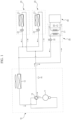
- an air conditioner includes an outdoor unit 10 arranged at an outdoor space to exchange heat with outdoor air, indoor units 20 to exchange heat with indoor air so as to heat and cool indoor spaces, respectively, a hot water generator 30 to heat water by refrigerant so as to generate hot water, and a hot water consuming device 40 to use the hot water generated by the hot water generator 30.
- hot or cold air generated through implementation of the refrigeration cycle of the air conditioner may be used to heat and cool the indoor space, and hot water generated by the hot water generator 30 may be supplied to the hot water consuming device 40 such as a floor heater or a hot water supply device.
- the outdoor unit 10 includes a compressor 11 to compress refrigerant, an outdoor heat exchanger 12 to allow the refrigerant to exchange heat with outdoor air, a four-way valve 13 to selectively supply the refrigerant compressed by the compressor 11 to any one of the outdoor heat exchanger 12 and each indoor unit 20, and a pressure sensing sensor 14 to sense pressure of the refrigerant discharged from the compressor 11, namely, pressure of the refrigerant which passes through a path provided at a discharge side of the compressor 11.
- the indoor unit 20 is comprised of a plurality of indoor units 20 which may independently heat and cool a plurality of indoor spaces, respectively.
- Such an indoor unit 20 is a device to heat and cool the indoor space while allowing the refrigerant supplied from the outdoor unit 10 to exchange heat with indoor air.
- Each indoor unit 20 includes an indoor heat exchanger 21 to allow the refrigerant to exchange heat with indoor air, and an air conditioning expansion valve 22 to decompress and expand the refrigerant.
- the hot water generator 30 is a device to heat water by the refrigerant supplied from the outdoor unit 10 so as to generate hot water.
- the hot water generator 30 includes a heating tank 31 to heat water while allowing the refrigerant supplied from the outdoor unit 10 to exchange heat with water supplied from the hot water consuming device 40, a hot water expansion valve 32 to decompress and expand the refrigerant passing through the heating tank 31, and a discharge water temperature sensing sensor 33 to sense temperature of the hot water which is supplied to the hot water consuming device 40 from the heating tank 31 after undergoing heat exchange with the refrigerant in the heating tank 31.
- the hot water expansion valve 32 is a flow regulating valve capable of controlling an opening degree thereof to regulate the amount of refrigerant which is supplied to the hot water generator 30.
- indoor heating by the indoor units 20 and hot water generation by the hot water generator 30 may be performed independently of each other. Consequently, either the maximum total amount of refrigerant used in the indoor units when all indoor units 20 are operated or the maximum amount of refrigerant used in the hot water generator 30 when the hot water generator 30 is operated at full load is practically equal to the amount of refrigerant supplied from the outdoor unit 10. Also, when the indoor heating by the indoor units 20 is performed simultaneously with the hot water generation by the hot water generator 30, the sum of the total amount of refrigerant used in indoor units 20 and the amount of refrigerant used in the hot water generator 30 is always maintained at or below the amount of refrigerant supplied from the outdoor unit 10, in order to prevent generation of a cold wind in the indoor units 20.
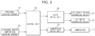
- the air conditioner also includes a control unit 50 to control overall operation of the air conditioner, a valve drive unit 60 to control the air conditioning expansion valve 22 and the hot water expansion valve 32, and a compressor drive unit 70 to control the compressor 11.
- the control unit 50 controls the air conditioning expansion valve 22, the hot water expansion valve 32, and the compressor 11 by the valve drive unit 60 and the compressor drive unit 70, based on pressure and temperature information transferred from the pressure sensing sensor 14 and discharge water temperature sensing sensor 33 described above.
- the control method of the air conditioner according to the present exemplary embodiment sums the amount of refrigerant used being used in one or more indoor units 20 in operation among a plurality of indoor units 20 to derive the total amount of refrigerant used ⁇ Q, and then opens the hot water expansion valve 32 to the opening degree thereof corresponding to the total amount of refrigerant used ⁇ Q, thereby regulating the amount of refrigerant which is supplied to the hot water generator 30. That is, the hot water expansion valve 32 is controlled so that refrigerant is first supplied to one or more indoor units 20 in operation from the outdoor unit 10, and is then supplied to the hot water generator 30. This serves to uniformly maintain the amount of refrigerant which is supplied to the indoor units 20, regardless of whether or not the hot water generator 30 is operated.
- the refrigerant which may be inadequately supplied to one or more of the indoor units 20 when the hot water generator 30 is operated during heating operation mode, from causing generation of a cold wind in the indoor units 20.
- the control method of the air conditioner if the hot water generator 30 is operated by a user (operation 100), first identifies whether there is not any one indoor unit 20 in operation among a plurality of indoor units 20 (operation 110). Thereafter, if there is no indoor unit 20 in operation among a plurality of indoor units 20, the hot water expansion valve 32 is opened to the maximum opening degree thereof (operation 120). In other words, if there is no indoor unit 20 in operation among a plurality of indoor units 20, all refrigerant supplied from the outdoor unit 10 is used to operate the hot water generator 30.
- the control method of the air conditioner senses refrigerant pressure P at the discharge side of the compressor 11 by the pressure sensing sensor 14 (operation 130) if there is any one indoor unit 20 in operation among a plurality of indoor units 20, and then indentifies whether the sensed refrigerant pressure P is less than the reference pressure Pref (operation 140). If the refrigerant pressure P is less than the reference pressure Pref, the hot water expansion valve 32 is opened to the minimum opening degree thereof (operation 150).
- the reference pressure Pref is the refrigerant pressure P at the discharge side of the compressor 11 during an operation mode of all the indoor units 20. Accordingly, when the hot water generator 30 is operated in a state in which the pressure at the discharge side of the compressor 11 is less than the reference pressure Pref, the refrigerant may be inadequately supplied to one or more of the indoor units 20. As a result, generation of a cold wind may be caused in the indoor units 20 in heating operation. Therefore, in such a case, the hot water generator 30 is opened to the minimum opening degree thereof so that the hot water generator 30 is practically not operated while preventing the refrigerant from remaining in the hot water generator 30.
- control method of the air conditioner senses temperature T of water which is discharged from the heating tank 31 of the hot water generator 30 by the discharge water temperature sensing sensor 33 mounted at the hot water generator 30 (operation 160) if the pressure P at the discharge side of the compressor 11 is equal to or greater than the reference pressure Pref, and then indentifies whether the sensed discharge water temperature T is less than the reference temperature Tref (operation 170).
- the refrigerant to exchange heat with water while passing through the heating tank 31 may be rapidly cooled by the water, thereby rapidly dropping the refrigerant pressure P at the discharge side of the compressor 11. Accordingly, when the refrigerant pressure P at the discharge side of the compressor 11 is rapidly dropped, the refrigerant may be inadequately supplied to one or more of the indoor units 20. As a result, generation of a cold wind may be caused in the indoor units 20 in heating operation. Therefore, when the discharge water temperature T is less than the reference temperature Tref, the hot water generator 30 is opened to the minimum opening degree thereof so that the hot water generator 30 is practically not operated while preventing the refrigerant from remaining in the hot water generator 30.
- the method may also be executed in reverse order. That is, the method may sense the discharge water temperature T (operation 160), and then identify the pressure P at the discharge side of the compressor 11 (operation 130) if the discharge water temperature T is equal to or greater than the reference temperature Tref.
- the control method of the air conditioner if the discharge water temperature T is equal to or greater than the reference temperature Tref, respectively identifies the amount of refrigerant used being used for heating in indoor units 20 in operation among a plurality of indoor units 20, and then sums the amount of refrigerant used in each indoor unit 20 in operation to indentify the total amount of refrigerant used ⁇ Q (operation 180). Subsequently, the hot water expansion valve 32 is opened to the opening degree thereof corresponding to the calculated total amount of refrigerant used ⁇ Q (operation 190).
- the opening degree of the hot water expansion valve 32 is controlled so that the remaining refrigerant, except for the total amount of refrigerant used ⁇ Q being used in the indoor units 20 in operation among refrigerant supplied from the outdoor unit 10, is supplied to the hot water generator 30.
- a range of the total amount of refrigerant used ⁇ Q in one or more indoor units 20 in operation among a plurality of indoor units 20 is set in a multistage manner to control the opening degree of the hot water expansion valve 32 according to the set range of the total amount of refrigerant used.
- the hot water expansion valve 32 is opened to the relatively small opening degree thereof to decrease the amount of refrigerant which is supplied to the hot water generator 30.
- the hot water expansion valve 32 is opened to the relatively great opening degree thereof to increase the amount of refrigerant which is supplied to the hot water generator 30.
- the opening degree of the hot water expansion valve 32 is controlled according to the total amount of refrigerant used in one or more indoor units 20 in operation, the amount of refrigerant to be supplied to the indoor units 20 may be sufficient even when the hot water generator 30 is operated during heating operation by the indoor units 20. As a result, it may be possible to prevent a cold wind from being generated in the indoor units 20.
- the present exemplary embodiment discloses an air conditioner including a plurality of indoor units 20, but is not limited thereto. Thus, an air conditioner including a single indoor unit 20 may also be applied.
- the air conditioner according to an aspect of the present disclosure may control the opening degree of the hot water expansion valve so that the remaining refrigerant, except for the total amount of refrigerant used being used in the indoor units among refrigerant supplied from the outdoor unit, is supplied to the hot water generator, thereby sufficiently supplying refrigerant to the indoor units in operation even when the hot water generator is operated.
Landscapes
- Engineering & Computer Science (AREA)
- Mechanical Engineering (AREA)
- General Engineering & Computer Science (AREA)
- Chemical & Material Sciences (AREA)
- Combustion & Propulsion (AREA)
- Physics & Mathematics (AREA)
- Thermal Sciences (AREA)
- Water Supply & Treatment (AREA)
- Air Conditioning Control Device (AREA)
- Heat-Pump Type And Storage Water Heaters (AREA)
- Compression-Type Refrigeration Machines With Reversible Cycles (AREA)
Claims (10)
- Steuerverfahren einer Klimaanlage, wobei die Klimaanlage eine Außeneinheit (10), eine oder mehrere Inneneinheiten (20) zum Heizen eines Innenraums durch ein von der Außeneinheit (10) zugeführtes Kältemittel und einen Warmwassererzeuger (30) zum Heizen von Wasser durch das von der Außeneinheit (10) zugeführte Kältemittel umfasst,Steuern der Zufuhr des Kältemittels durch eine Steuereinheit (50), so dass das Kältemittel zunächst einem oder mehreren in Betrieb befindlichen Inneneinheiten (20) von der Außeneinheit (10) zugeführt wird und anschließend dem Warmwassererzeuger zugeführt wird,gekennzeichnet durchwobei das Steuern der Zufuhr des Kältemittels durch Steuern eines Öffnungsgrades eines am Warmwassererzeuger (30) angeordneten Warmwasser-Expansionsventils (32) erfolgt;Messen eines Drucks auf einer Druckseite eines Kompressors der Außeneinheit;Steuern einer Zufuhr von Kältemittel zu einem oder mehreren der einen oder mehreren Inneneinheiten und zum Warmwassererzeuger basierend auf dem gemessenen Druck des Kältemittels an der Druckseite des Kompressors der Außeneinheit, um zu verhindern, dass das Kältemittel die eine oder mehreren Inneneinheiten oder den Warmwassererzeuger kühlt;Identifizieren, ob keine der einen oder mehreren Inneneinheiten in Betrieb ist;Identifizieren, ob der Druck an der Druckseite eines Kompressors der Außeneinheit kleiner ist als ein Referenzdruck; undwenn der identifizierte Druck auf der Druckseite des Kompressors kleiner ist als der Referenzdruck und wenn eine oder mehrere der Inneneinheiten als in Betrieb befindlich identifiziert wird, Öffnen des Warmwasser-Expansionsventils auf einen Mindestöffnungsgrad.
- Steuerverfahren der Klimaanlage nach Anspruch 1, ferner umfassend:Identifizieren, ob keine Inneneinheit (20) von den Inneneinheiten (20) in Betrieb ist; undwenn keine Inneneinheit (20) in Betrieb ist, Öffnen des Warmwasser-Expansionsventils (32) des Warmwasserbereiters (30) auf dessen Maximalöffnungsgrad.
- Steuerverfahren der Klimaanlage nach Anspruch 1, ferner umfassend:Identifizieren, ob keine Inneneinheit (20) von den Inneneinheiten (20) in Betrieb ist;wenn eine Inneneinheit (20) in Betrieb ist, Identifizieren einer Temperatur von Wassers, das aus dem Warmwassererzeuger (30) austritt; undwenn die Temperatur des austretenden Wassers kleiner ist als eine Referenztemperatur, Öffnen des Warmwasser-Expansionsventils (32) auf dessen Mindestöffnungsgrad.
- Steuerverfahren der Klimaanlage nach Anspruch 1, ferner umfassend:Identifizieren, ob eine oder mehrere Inneneinheiten (20) von den Inneneinheiten (20) in Betrieb sind;Identifizieren der Kältemittelmenge, die in einer oder mehreren Inneneinheiten (20) von den Inneneinheiten (20) im Betrieb verbraucht wird;Summieren der gesamten Kältemittelmenge, die in einer oder mehreren Inneneinheiten (20) im Betrieb verbraucht wird, um die Gesamtmenge des verbrauchten Kältemittels zu berechnen; undÖffnen des Warmwasser-Expansionsventils (32) auf den Öffnungsgrad, welcher der Gesamtmenge des verbrauchten Kältemittels entspricht.
- Steuerverfahren der Klimaanlage nach Anspruch 4, wobei:wenn die Gesamtmenge des in einer oder mehreren Inneneinheiten (20) verbrauchten Kältemittels relativ groß ist, das Warmwasser-Expansionsventil (32) auf dessen relativ kleinen Öffnungsgrad geöffnet wird; undwenn die Gesamtmenge des in einer oder mehreren Inneneinheiten (20) verbrauchten Kältemittels relativ klein ist, das Warmwasser-Expansionsventil (32) auf einen relativ großen Öffnungsgrad geöffnet wird.
- Steuerverfahren der Klimaanlage nach Anspruch 1, wobei:sowohl die maximale Gesamtmenge des in einer oder mehreren Inneneinheiten (20) verbrauchten Kältemittels als auch die maximale Menge des im Warmwassererzeuger verbrauchten Kältemittels gleich der Menge des Kältemittels ist, das von der Außeneinheit (10) zugeführt wird; unddie Summe der Gesamtmenge des in einer oder mehreren Inneneinheiten (20) von den Inneneinheiten (20) im Betrieb verbrauchten Kältemittels und der Menge des im Warmwassererzeuger im Betrieb verbrauchten Kältemittels kleiner gleich der Menge des Kältemittels ist, das von der Außeneinheit (10) zugeführt wird.
- Klimaanlage, umfassend:eine Außeneinheit (10),eine oder mehrere Inneneinheiten (20) zum Heizen eines Innenraums durch von der Außeneinheit (10) zugeführtes Kältemittel,einen Warmwassererzeuger (30) zum Erhitzen von Wasser durch von der Außengerät (10) zugeführtes Kältemittel,gekennzeichnet durchein Warmwasser-Expansionsventil (32), angeordnet am Warmwassererzeuger (30) zum Steuern der Menge des Kältemittels, das dem Warmwassererzeuger (30) zugeführt wird, wobei das Warmwasser-Expansionsventil (32) als Durchflussregelventil gebildet ist, das in der Lage ist, einen Öffnungsgrad von diesem zu steuern; undeine Steuereinheit (50), ausgebildet zum Ermöglichen, dass das Warmwasser-Expansionsventil (32) bis zu einem Öffnungsgrad geöffnet wird, welcher der Gesamtmenge des in der einen oder den mehreren Inneneinheiten (20) verbrauchten Kältemittels entspricht, zum Identifizieren des Drucks an einer Druckseite des Kompressors der Außeneinheit und zum Steuern des Öffnens des Warmwasser-Expansionsventils auf einen Mindestöffnungsgrad basierend darauf, ob der identifizierte Druck an der Druckseite des Kompressors kleiner ist als der Referenzdruck und ob eine der einen oder mehreren Inneneinheiten als in Betrieb befindlich identifiziert wird.
- Klimaanlage nach Anspruch 7, wobei die Steuereinheit (50) identifiziert, ob keine Inneneinheit (20) in Betrieb ist, und anschließend das Warmwasser-Expansionsventil (32) auf den Maximalöffnungsgrad öffnet, wenn keine Inneneinheit (20) in Betrieb ist.
- Klimaanlage nach Anspruch 7, wobei:die Außeneinheit (10) einen Kompressor (11) zum Komprimieren von Kältemittel und einen Drucksensor zum Erfassen eines Drucks an einer Druckseite des Kompressors (11) umfasst; unddie Steuereinheit (50) den Druck an der Druckseite des Kompressors (11) identifiziert und anschließend das Warmwasser-Expansionsventil (32) auf dessen Mindestöffnungsgrad öffnet, wenn der Druck an der Druckseite des Kompressors (11) kleiner gleich dem Referenzdruck ist.
- Klimaanlage nach Anspruch 7, wobei:der Warmwassererzeuger (30) einen Heiztank (31) zum Heizen von Wasser durch Kältemittel und einen Auslasswasser-Temperatursensor zum Erfassen einer Temperatur von Wasser, das aus dem Heiztank (31) ausgelassen wird, umfasst; unddie Steuereinheit (50) die Temperatur des Wassers, dass aus dem Heiztank (31) ausgelassen wird, identifiziert und anschließend das Warmwasser-Expansionsventil (32) auf dessen Mindestöffnungsgrad öffnet, wenn die Temperatur des ausgelassenen Wassers kleiner gleich einer Referenztemperatur ist.
Applications Claiming Priority (1)
| Application Number | Priority Date | Filing Date | Title |
|---|---|---|---|
| KR1020100088105A KR101505856B1 (ko) | 2010-09-08 | 2010-09-08 | 공기조화기 및 그 제어방법 |
Publications (3)
| Publication Number | Publication Date |
|---|---|
| EP2428740A2 EP2428740A2 (de) | 2012-03-14 |
| EP2428740A3 EP2428740A3 (de) | 2018-03-14 |
| EP2428740B1 true EP2428740B1 (de) | 2024-11-20 |
Family
ID=44674392
Family Applications (1)
| Application Number | Title | Priority Date | Filing Date |
|---|---|---|---|
| EP11179673.6A Active EP2428740B1 (de) | 2010-09-08 | 2011-09-01 | Klimaanlage und Betriebsverfahren dafür |
Country Status (4)
| Country | Link |
|---|---|
| US (1) | US20120055177A1 (de) |
| EP (1) | EP2428740B1 (de) |
| KR (1) | KR101505856B1 (de) |
| CN (1) | CN102401450B (de) |
Families Citing this family (12)
| Publication number | Priority date | Publication date | Assignee | Title |
|---|---|---|---|---|
| US9631847B2 (en) * | 2011-10-04 | 2017-04-25 | Mitsubishi Electric Corporation | Refrigeration cycle apparatus |
| JP5669958B2 (ja) * | 2011-11-30 | 2015-02-18 | 三菱電機株式会社 | 空調システムの施工時における利用側熱交換器の熱媒体選定方法 |
| KR101255760B1 (ko) * | 2012-05-30 | 2013-04-17 | 오텍캐리어 주식회사 | 하이브리드 히트펌프 보일러 시스템 |
| FR2998354B1 (fr) * | 2012-11-22 | 2014-12-19 | Chauffage Sic Soc Ind De | Module interieur compact pour installation de regulation thermique a pompe a chaleur |
| US20150040841A1 (en) * | 2013-08-06 | 2015-02-12 | Carrier Corporation | System and method for improving a water heating cycle in a multi-purpose hvac system |
| CN103363720B (zh) * | 2013-08-06 | 2015-07-08 | 特灵空调系统(中国)有限公司 | 多功能空调热水系统 |
| CN103604246B (zh) * | 2013-10-25 | 2017-01-04 | 四川长虹电器股份有限公司 | 一种温度调节设备 |
| WO2015125509A1 (ja) * | 2014-02-18 | 2015-08-27 | 東芝キヤリア株式会社 | 冷凍サイクル装置 |
| CN105588304B (zh) * | 2015-07-24 | 2018-11-30 | 青岛海信日立空调系统有限公司 | 一种室内机及其控制方法 |
| US10823471B2 (en) * | 2018-05-23 | 2020-11-03 | Carrier Corporation | Refrigerant transfer control in multi mode air conditioner with hot water generator |
| EP3819551A1 (de) | 2019-11-07 | 2021-05-12 | E.ON Sverige AB | Verfahren und steuereinheit zur steuerung eines steuerventils zur steuerung eines durchflusses einer wärmeübertragungsflüssigkeit in eine wärmeenergieextraktionseinheit |
| CN120368547A (zh) * | 2024-05-28 | 2025-07-25 | 青岛海尔空调电子有限公司 | 一种空调热水一体机及其控制方法、计算机程序产品 |
Family Cites Families (18)
| Publication number | Priority date | Publication date | Assignee | Title |
|---|---|---|---|---|
| KR900000809B1 (ko) * | 1984-02-09 | 1990-02-17 | 미쓰비시전기 주식회사 | 냉난방 · 급탕용(給湯用) 히트펌프장치 |
| JPH0849936A (ja) * | 1994-08-03 | 1996-02-20 | Matsushita Refrig Co Ltd | 蓄熱式空気調和機 |
| US5791155A (en) * | 1997-06-06 | 1998-08-11 | Carrier Corporation | System for monitoring expansion valve |
| KR101013377B1 (ko) * | 2003-12-30 | 2011-02-14 | 삼성전자주식회사 | 복합 냉난방 시스템 |
| KR100546616B1 (ko) * | 2004-01-19 | 2006-01-26 | 엘지전자 주식회사 | 멀티공기조화기의 제어방법 |
| CN2685748Y (zh) * | 2004-02-18 | 2005-03-16 | 广东科龙电器股份有限公司 | 分体式冷暖空调热水器 |
| KR100550566B1 (ko) * | 2004-02-25 | 2006-02-10 | 엘지전자 주식회사 | 멀티형 히트 펌프의 제어 방법 |
| KR100640856B1 (ko) * | 2004-12-14 | 2006-11-02 | 엘지전자 주식회사 | 멀티 공기조화기의 제어방법 |
| KR100640858B1 (ko) * | 2004-12-14 | 2006-11-02 | 엘지전자 주식회사 | 공기조화기 및 그 제어방법 |
| KR101119335B1 (ko) * | 2005-02-15 | 2012-03-06 | 엘지전자 주식회사 | 냉난방 동시형 멀티 에어컨 및 그의 응축냉매 제어방법 |
| JP2006283989A (ja) * | 2005-03-31 | 2006-10-19 | Sanyo Electric Co Ltd | 冷暖房システム |
| JP4069947B2 (ja) * | 2006-05-26 | 2008-04-02 | ダイキン工業株式会社 | 冷凍装置 |
| JP5125124B2 (ja) | 2007-01-31 | 2013-01-23 | ダイキン工業株式会社 | 冷凍装置 |
| KR101162756B1 (ko) * | 2007-02-24 | 2012-07-05 | 삼성전자주식회사 | 수냉식 공기조화기 및 그 제어방법 |
| JP4285583B2 (ja) * | 2007-05-30 | 2009-06-24 | ダイキン工業株式会社 | 空気調和装置 |
| KR101510378B1 (ko) * | 2008-02-20 | 2015-04-14 | 엘지전자 주식회사 | 공기 조화기 및 그의 제어방법 |
| JP5404487B2 (ja) * | 2010-03-23 | 2014-01-29 | 三菱電機株式会社 | 多室形空気調和機 |
| JP5674572B2 (ja) * | 2011-07-06 | 2015-02-25 | 三菱電機株式会社 | 空気調和機 |
-
2010
- 2010-09-08 KR KR1020100088105A patent/KR101505856B1/ko active Active
-
2011
- 2011-08-26 US US13/137,585 patent/US20120055177A1/en not_active Abandoned
- 2011-09-01 EP EP11179673.6A patent/EP2428740B1/de active Active
- 2011-09-08 CN CN201110272501.1A patent/CN102401450B/zh not_active Expired - Fee Related
Also Published As
| Publication number | Publication date |
|---|---|
| EP2428740A3 (de) | 2018-03-14 |
| CN102401450A (zh) | 2012-04-04 |
| EP2428740A2 (de) | 2012-03-14 |
| US20120055177A1 (en) | 2012-03-08 |
| CN102401450B (zh) | 2016-03-30 |
| KR101505856B1 (ko) | 2015-03-25 |
| KR20120025915A (ko) | 2012-03-16 |
Similar Documents
| Publication | Publication Date | Title |
|---|---|---|
| EP2428740B1 (de) | Klimaanlage und Betriebsverfahren dafür | |
| EP2148147B1 (de) | Steuerungsverfahren für eine Klimaanlage | |
| US8036779B2 (en) | Air-conditioning system controller | |
| US20110203298A1 (en) | Heat pump system and control method thereof | |
| JP5204987B2 (ja) | 空調システムおよび空調システムの制御方法 | |
| KR20100110423A (ko) | 공기 조화기 및 공기 조화기의 제어 방법 | |
| JP6609697B2 (ja) | 熱源システム、及び熱源システムの制御方法 | |
| JP2008064439A (ja) | 空気調和装置 | |
| JP6363428B2 (ja) | 熱媒体循環システム | |
| KR101883368B1 (ko) | 냉동기 시스템 운전비 절감을 위한 냉방시스템 제어방법 | |
| CN100593099C (zh) | 空气调节装置 | |
| JP2011257098A (ja) | ヒートポンプサイクル装置 | |
| KR20100048194A (ko) | 공기조화기 및 그 동작방법 | |
| KR101573363B1 (ko) | 공기조화기 및 그 제어방법 | |
| JP2016102636A (ja) | 空調システム | |
| JP6430758B2 (ja) | 冷却システム | |
| JP6134511B2 (ja) | 直膨コイルを使用した空気調和機 | |
| CN120265925A (zh) | 制冷制热装置 | |
| JP7199529B2 (ja) | 制御装置、空気環境調整システム、空気環境調整方法、プログラム、及び記録媒体 | |
| JP3835310B2 (ja) | 空気調和機 | |
| JP7018775B2 (ja) | 空気調和システム | |
| JP2004232934A (ja) | マルチ型空気調和機の制御方法 | |
| KR20170075371A (ko) | 공기조화기 및 그 동작방법 | |
| KR102817029B1 (ko) | 공기조화기 | |
| JP5940608B2 (ja) | 熱媒体循環システム |
Legal Events
| Date | Code | Title | Description |
|---|---|---|---|
| AK | Designated contracting states |
Kind code of ref document: A2 Designated state(s): AL AT BE BG CH CY CZ DE DK EE ES FI FR GB GR HR HU IE IS IT LI LT LU LV MC MK MT NL NO PL PT RO RS SE SI SK SM TR |
|
| AX | Request for extension of the european patent |
Extension state: BA ME |
|
| PUAI | Public reference made under article 153(3) epc to a published international application that has entered the european phase |
Free format text: ORIGINAL CODE: 0009012 |
|
| RAP1 | Party data changed (applicant data changed or rights of an application transferred) |
Owner name: SAMSUNG ELECTRONICS CO., LTD. |
|
| PUAL | Search report despatched |
Free format text: ORIGINAL CODE: 0009013 |
|
| AK | Designated contracting states |
Kind code of ref document: A3 Designated state(s): AL AT BE BG CH CY CZ DE DK EE ES FI FR GB GR HR HU IE IS IT LI LT LU LV MC MK MT NL NO PL PT RO RS SE SI SK SM TR |
|
| AX | Request for extension of the european patent |
Extension state: BA ME |
|
| RIC1 | Information provided on ipc code assigned before grant |
Ipc: F24F 3/06 20060101AFI20180205BHEP Ipc: F24F 11/00 20180101ALI20180205BHEP Ipc: F24D 19/10 20060101ALI20180205BHEP Ipc: F24D 17/02 20060101ALI20180205BHEP Ipc: F25B 13/00 20060101ALI20180205BHEP Ipc: F24F 11/06 00000000ALI20180205BHEP |
|
| STAA | Information on the status of an ep patent application or granted ep patent |
Free format text: STATUS: REQUEST FOR EXAMINATION WAS MADE |
|
| 17P | Request for examination filed |
Effective date: 20180607 |
|
| RBV | Designated contracting states (corrected) |
Designated state(s): AL AT BE BG CH CY CZ DE DK EE ES FI FR GB GR HR HU IE IS IT LI LT LU LV MC MK MT NL NO PL PT RO RS SE SI SK SM TR |
|
| RIC1 | Information provided on ipc code assigned before grant |
Ipc: F24F 3/06 20060101AFI20180205BHEP Ipc: F24D 19/10 20060101ALI20180205BHEP Ipc: F24D 17/02 20060101ALI20180205BHEP Ipc: F24F 11/06 20181130ALI20180205BHEP Ipc: F24F 11/00 20180101ALI20180205BHEP Ipc: F25B 13/00 20060101ALI20180205BHEP |
|
| RIC1 | Information provided on ipc code assigned before grant |
Ipc: F24F 11/06 20060101ALI20180205BHEP Ipc: F24D 17/02 20060101ALI20180205BHEP Ipc: F25B 13/00 20060101ALI20180205BHEP Ipc: F24F 3/06 20060101AFI20180205BHEP Ipc: F24F 11/00 20180101ALI20180205BHEP Ipc: F24D 19/10 20060101ALI20180205BHEP |
|
| STAA | Information on the status of an ep patent application or granted ep patent |
Free format text: STATUS: EXAMINATION IS IN PROGRESS |
|
| 17Q | First examination report despatched |
Effective date: 20190527 |
|
| REG | Reference to a national code |
Ref country code: DE Ref legal event code: R079 Free format text: PREVIOUS MAIN CLASS: F24F0003060000 Ipc: F24F0011000000 Ref country code: DE Ref legal event code: R079 Ref document number: 602011075104 Country of ref document: DE Free format text: PREVIOUS MAIN CLASS: F24F0003060000 Ipc: F24F0011000000 |
|
| RIC1 | Information provided on ipc code assigned before grant |
Ipc: F24D 19/10 20060101ALI20240415BHEP Ipc: F25B 13/00 20060101ALI20240415BHEP Ipc: F24F 3/06 20060101ALI20240415BHEP Ipc: F24F 11/00 20060101AFI20240415BHEP |
|
| GRAP | Despatch of communication of intention to grant a patent |
Free format text: ORIGINAL CODE: EPIDOSNIGR1 |
|
| STAA | Information on the status of an ep patent application or granted ep patent |
Free format text: STATUS: GRANT OF PATENT IS INTENDED |
|
| INTG | Intention to grant announced |
Effective date: 20240617 |
|
| GRAS | Grant fee paid |
Free format text: ORIGINAL CODE: EPIDOSNIGR3 |
|
| GRAA | (expected) grant |
Free format text: ORIGINAL CODE: 0009210 |
|
| STAA | Information on the status of an ep patent application or granted ep patent |
Free format text: STATUS: THE PATENT HAS BEEN GRANTED |
|
| AK | Designated contracting states |
Kind code of ref document: B1 Designated state(s): AL AT BE BG CH CY CZ DE DK EE ES FI FR GB GR HR HU IE IS IT LI LT LU LV MC MK MT NL NO PL PT RO RS SE SI SK SM TR |
|
| REG | Reference to a national code |
Ref country code: GB Ref legal event code: FG4D |
|
| REG | Reference to a national code |
Ref country code: CH Ref legal event code: EP |
|
| REG | Reference to a national code |
Ref country code: DE Ref legal event code: R096 Ref document number: 602011075104 Country of ref document: DE |
|
| REG | Reference to a national code |
Ref country code: IE Ref legal event code: FG4D |
|
| REG | Reference to a national code |
Ref country code: LT Ref legal event code: MG9D |
|
| REG | Reference to a national code |
Ref country code: NL Ref legal event code: MP Effective date: 20241120 |
|
| PG25 | Lapsed in a contracting state [announced via postgrant information from national office to epo] |
Ref country code: PT Free format text: LAPSE BECAUSE OF FAILURE TO SUBMIT A TRANSLATION OF THE DESCRIPTION OR TO PAY THE FEE WITHIN THE PRESCRIBED TIME-LIMIT Effective date: 20250320 Ref country code: IS Free format text: LAPSE BECAUSE OF FAILURE TO SUBMIT A TRANSLATION OF THE DESCRIPTION OR TO PAY THE FEE WITHIN THE PRESCRIBED TIME-LIMIT Effective date: 20250320 Ref country code: HR Free format text: LAPSE BECAUSE OF FAILURE TO SUBMIT A TRANSLATION OF THE DESCRIPTION OR TO PAY THE FEE WITHIN THE PRESCRIBED TIME-LIMIT Effective date: 20241120 |
|
| PG25 | Lapsed in a contracting state [announced via postgrant information from national office to epo] |
Ref country code: FI Free format text: LAPSE BECAUSE OF FAILURE TO SUBMIT A TRANSLATION OF THE DESCRIPTION OR TO PAY THE FEE WITHIN THE PRESCRIBED TIME-LIMIT Effective date: 20241120 Ref country code: NL Free format text: LAPSE BECAUSE OF FAILURE TO SUBMIT A TRANSLATION OF THE DESCRIPTION OR TO PAY THE FEE WITHIN THE PRESCRIBED TIME-LIMIT Effective date: 20241120 |
|
| REG | Reference to a national code |
Ref country code: AT Ref legal event code: MK05 Ref document number: 1743889 Country of ref document: AT Kind code of ref document: T Effective date: 20241120 |
|
| PG25 | Lapsed in a contracting state [announced via postgrant information from national office to epo] |
Ref country code: BG Free format text: LAPSE BECAUSE OF FAILURE TO SUBMIT A TRANSLATION OF THE DESCRIPTION OR TO PAY THE FEE WITHIN THE PRESCRIBED TIME-LIMIT Effective date: 20241120 |
|
| PG25 | Lapsed in a contracting state [announced via postgrant information from national office to epo] |
Ref country code: ES Free format text: LAPSE BECAUSE OF FAILURE TO SUBMIT A TRANSLATION OF THE DESCRIPTION OR TO PAY THE FEE WITHIN THE PRESCRIBED TIME-LIMIT Effective date: 20241120 |
|
| PG25 | Lapsed in a contracting state [announced via postgrant information from national office to epo] |
Ref country code: NO Free format text: LAPSE BECAUSE OF FAILURE TO SUBMIT A TRANSLATION OF THE DESCRIPTION OR TO PAY THE FEE WITHIN THE PRESCRIBED TIME-LIMIT Effective date: 20250220 |
|
| PG25 | Lapsed in a contracting state [announced via postgrant information from national office to epo] |
Ref country code: GR Free format text: LAPSE BECAUSE OF FAILURE TO SUBMIT A TRANSLATION OF THE DESCRIPTION OR TO PAY THE FEE WITHIN THE PRESCRIBED TIME-LIMIT Effective date: 20250221 Ref country code: AT Free format text: LAPSE BECAUSE OF FAILURE TO SUBMIT A TRANSLATION OF THE DESCRIPTION OR TO PAY THE FEE WITHIN THE PRESCRIBED TIME-LIMIT Effective date: 20241120 Ref country code: LV Free format text: LAPSE BECAUSE OF FAILURE TO SUBMIT A TRANSLATION OF THE DESCRIPTION OR TO PAY THE FEE WITHIN THE PRESCRIBED TIME-LIMIT Effective date: 20241120 |
|
| PG25 | Lapsed in a contracting state [announced via postgrant information from national office to epo] |
Ref country code: PL Free format text: LAPSE BECAUSE OF FAILURE TO SUBMIT A TRANSLATION OF THE DESCRIPTION OR TO PAY THE FEE WITHIN THE PRESCRIBED TIME-LIMIT Effective date: 20241120 |
|
| PG25 | Lapsed in a contracting state [announced via postgrant information from national office to epo] |
Ref country code: RS Free format text: LAPSE BECAUSE OF FAILURE TO SUBMIT A TRANSLATION OF THE DESCRIPTION OR TO PAY THE FEE WITHIN THE PRESCRIBED TIME-LIMIT Effective date: 20250220 |
|
| PG25 | Lapsed in a contracting state [announced via postgrant information from national office to epo] |
Ref country code: SM Free format text: LAPSE BECAUSE OF FAILURE TO SUBMIT A TRANSLATION OF THE DESCRIPTION OR TO PAY THE FEE WITHIN THE PRESCRIBED TIME-LIMIT Effective date: 20241120 |
|
| PG25 | Lapsed in a contracting state [announced via postgrant information from national office to epo] |
Ref country code: DK Free format text: LAPSE BECAUSE OF FAILURE TO SUBMIT A TRANSLATION OF THE DESCRIPTION OR TO PAY THE FEE WITHIN THE PRESCRIBED TIME-LIMIT Effective date: 20241120 |
|
| PG25 | Lapsed in a contracting state [announced via postgrant information from national office to epo] |
Ref country code: EE Free format text: LAPSE BECAUSE OF FAILURE TO SUBMIT A TRANSLATION OF THE DESCRIPTION OR TO PAY THE FEE WITHIN THE PRESCRIBED TIME-LIMIT Effective date: 20241120 |
|
| PG25 | Lapsed in a contracting state [announced via postgrant information from national office to epo] |
Ref country code: RO Free format text: LAPSE BECAUSE OF FAILURE TO SUBMIT A TRANSLATION OF THE DESCRIPTION OR TO PAY THE FEE WITHIN THE PRESCRIBED TIME-LIMIT Effective date: 20241120 |
|
| PG25 | Lapsed in a contracting state [announced via postgrant information from national office to epo] |
Ref country code: SK Free format text: LAPSE BECAUSE OF FAILURE TO SUBMIT A TRANSLATION OF THE DESCRIPTION OR TO PAY THE FEE WITHIN THE PRESCRIBED TIME-LIMIT Effective date: 20241120 |
|
| PG25 | Lapsed in a contracting state [announced via postgrant information from national office to epo] |
Ref country code: CZ Free format text: LAPSE BECAUSE OF FAILURE TO SUBMIT A TRANSLATION OF THE DESCRIPTION OR TO PAY THE FEE WITHIN THE PRESCRIBED TIME-LIMIT Effective date: 20241120 |
|
| PG25 | Lapsed in a contracting state [announced via postgrant information from national office to epo] |
Ref country code: IT Free format text: LAPSE BECAUSE OF FAILURE TO SUBMIT A TRANSLATION OF THE DESCRIPTION OR TO PAY THE FEE WITHIN THE PRESCRIBED TIME-LIMIT Effective date: 20241120 |
|
| REG | Reference to a national code |
Ref country code: DE Ref legal event code: R097 Ref document number: 602011075104 Country of ref document: DE |
|
| PG25 | Lapsed in a contracting state [announced via postgrant information from national office to epo] |
Ref country code: SE Free format text: LAPSE BECAUSE OF FAILURE TO SUBMIT A TRANSLATION OF THE DESCRIPTION OR TO PAY THE FEE WITHIN THE PRESCRIBED TIME-LIMIT Effective date: 20241120 |
|
| PLBE | No opposition filed within time limit |
Free format text: ORIGINAL CODE: 0009261 |
|
| STAA | Information on the status of an ep patent application or granted ep patent |
Free format text: STATUS: NO OPPOSITION FILED WITHIN TIME LIMIT |
|
| PGFP | Annual fee paid to national office [announced via postgrant information from national office to epo] |
Ref country code: DE Payment date: 20250820 Year of fee payment: 15 |
|
| 26N | No opposition filed |
Effective date: 20250821 |