EP2428355A1 - Verfahren und Maschine zur Herstellung eines Behälters, insbesondere eines Behälters für gießbare Lebensmittelprodukte - Google Patents
Verfahren und Maschine zur Herstellung eines Behälters, insbesondere eines Behälters für gießbare Lebensmittelprodukte Download PDFInfo
- Publication number
- EP2428355A1 EP2428355A1 EP10176717A EP10176717A EP2428355A1 EP 2428355 A1 EP2428355 A1 EP 2428355A1 EP 10176717 A EP10176717 A EP 10176717A EP 10176717 A EP10176717 A EP 10176717A EP 2428355 A1 EP2428355 A1 EP 2428355A1
- Authority
- EP
- European Patent Office
- Prior art keywords
- axis
- forming member
- sheet
- sleeve
- main portion
- Prior art date
- Legal status (The legal status is an assumption and is not a legal conclusion. Google has not performed a legal analysis and makes no representation as to the accuracy of the status listed.)
- Granted
Links
Images


Classifications
-
- B—PERFORMING OPERATIONS; TRANSPORTING
- B31—MAKING ARTICLES OF PAPER, CARDBOARD OR MATERIAL WORKED IN A MANNER ANALOGOUS TO PAPER; WORKING PAPER, CARDBOARD OR MATERIAL WORKED IN A MANNER ANALOGOUS TO PAPER
- B31C—MAKING WOUND ARTICLES, e.g. WOUND TUBES, OF PAPER, CARDBOARD OR MATERIAL WORKED IN A MANNER ANALOGOUS TO PAPER
- B31C1/00—Making tubes or pipes by feeding at right angles to the winding mandrel centre line
-
- B—PERFORMING OPERATIONS; TRANSPORTING
- B31—MAKING ARTICLES OF PAPER, CARDBOARD OR MATERIAL WORKED IN A MANNER ANALOGOUS TO PAPER; WORKING PAPER, CARDBOARD OR MATERIAL WORKED IN A MANNER ANALOGOUS TO PAPER
- B31B—MAKING CONTAINERS OF PAPER, CARDBOARD OR MATERIAL WORKED IN A MANNER ANALOGOUS TO PAPER
- B31B50/00—Making rigid or semi-rigid containers, e.g. boxes or cartons
- B31B50/74—Auxiliary operations
- B31B50/81—Forming or attaching accessories, e.g. opening devices, closures or tear strings
- B31B50/84—Forming or attaching means for filling or dispensing contents, e.g. valves or spouts
-
- B—PERFORMING OPERATIONS; TRANSPORTING
- B31—MAKING ARTICLES OF PAPER, CARDBOARD OR MATERIAL WORKED IN A MANNER ANALOGOUS TO PAPER; WORKING PAPER, CARDBOARD OR MATERIAL WORKED IN A MANNER ANALOGOUS TO PAPER
- B31C—MAKING WOUND ARTICLES, e.g. WOUND TUBES, OF PAPER, CARDBOARD OR MATERIAL WORKED IN A MANNER ANALOGOUS TO PAPER
- B31C1/00—Making tubes or pipes by feeding at right angles to the winding mandrel centre line
- B31C1/02—Machines therefor having additional mandrels
-
- B—PERFORMING OPERATIONS; TRANSPORTING
- B65—CONVEYING; PACKING; STORING; HANDLING THIN OR FILAMENTARY MATERIAL
- B65D—CONTAINERS FOR STORAGE OR TRANSPORT OF ARTICLES OR MATERIALS, e.g. BAGS, BARRELS, BOTTLES, BOXES, CANS, CARTONS, CRATES, DRUMS, JARS, TANKS, HOPPERS, FORWARDING CONTAINERS; ACCESSORIES, CLOSURES, OR FITTINGS THEREFOR; PACKAGING ELEMENTS; PACKAGES
- B65D15/00—Containers having bodies formed by interconnecting or uniting two or more rigid, or substantially rigid, sections made of different materials
- B65D15/02—Containers having bodies formed by interconnecting or uniting two or more rigid, or substantially rigid, sections made of different materials of curved, or partially curved, cross-section, e.g. cans, drums
- B65D15/04—Containers having bodies formed by interconnecting or uniting two or more rigid, or substantially rigid, sections made of different materials of curved, or partially curved, cross-section, e.g. cans, drums with curved, or partially curved, walls made by winding or bending paper
- B65D15/08—Containers having bodies formed by interconnecting or uniting two or more rigid, or substantially rigid, sections made of different materials of curved, or partially curved, cross-section, e.g. cans, drums with curved, or partially curved, walls made by winding or bending paper with end walls made of plastics material
-
- B—PERFORMING OPERATIONS; TRANSPORTING
- B65—CONVEYING; PACKING; STORING; HANDLING THIN OR FILAMENTARY MATERIAL
- B65D—CONTAINERS FOR STORAGE OR TRANSPORT OF ARTICLES OR MATERIALS, e.g. BAGS, BARRELS, BOTTLES, BOXES, CANS, CARTONS, CRATES, DRUMS, JARS, TANKS, HOPPERS, FORWARDING CONTAINERS; ACCESSORIES, CLOSURES, OR FITTINGS THEREFOR; PACKAGING ELEMENTS; PACKAGES
- B65D3/00—Rigid or semi-rigid containers having bodies or peripheral walls of curved or partially-curved cross-section made by winding or bending paper without folding along defined lines
- B65D3/02—Rigid or semi-rigid containers having bodies or peripheral walls of curved or partially-curved cross-section made by winding or bending paper without folding along defined lines characterised by shape
- B65D3/04—Rigid or semi-rigid containers having bodies or peripheral walls of curved or partially-curved cross-section made by winding or bending paper without folding along defined lines characterised by shape essentially cylindrical
-
- B—PERFORMING OPERATIONS; TRANSPORTING
- B65—CONVEYING; PACKING; STORING; HANDLING THIN OR FILAMENTARY MATERIAL
- B65D—CONTAINERS FOR STORAGE OR TRANSPORT OF ARTICLES OR MATERIALS, e.g. BAGS, BARRELS, BOTTLES, BOXES, CANS, CARTONS, CRATES, DRUMS, JARS, TANKS, HOPPERS, FORWARDING CONTAINERS; ACCESSORIES, CLOSURES, OR FITTINGS THEREFOR; PACKAGING ELEMENTS; PACKAGES
- B65D3/00—Rigid or semi-rigid containers having bodies or peripheral walls of curved or partially-curved cross-section made by winding or bending paper without folding along defined lines
- B65D3/10—Rigid or semi-rigid containers having bodies or peripheral walls of curved or partially-curved cross-section made by winding or bending paper without folding along defined lines characterised by form of integral or permanently secured end closure
- B65D3/20—Rigid or semi-rigid containers having bodies or peripheral walls of curved or partially-curved cross-section made by winding or bending paper without folding along defined lines characterised by form of integral or permanently secured end closure with end portion of body adapted to be closed, by flattening or folding operations, e.g. formed with crease lines or flaps
-
- B—PERFORMING OPERATIONS; TRANSPORTING
- B65—CONVEYING; PACKING; STORING; HANDLING THIN OR FILAMENTARY MATERIAL
- B65D—CONTAINERS FOR STORAGE OR TRANSPORT OF ARTICLES OR MATERIALS, e.g. BAGS, BARRELS, BOTTLES, BOXES, CANS, CARTONS, CRATES, DRUMS, JARS, TANKS, HOPPERS, FORWARDING CONTAINERS; ACCESSORIES, CLOSURES, OR FITTINGS THEREFOR; PACKAGING ELEMENTS; PACKAGES
- B65D3/00—Rigid or semi-rigid containers having bodies or peripheral walls of curved or partially-curved cross-section made by winding or bending paper without folding along defined lines
- B65D3/22—Rigid or semi-rigid containers having bodies or peripheral walls of curved or partially-curved cross-section made by winding or bending paper without folding along defined lines with double walls; with walls incorporating air-chambers; with walls made of laminated material
-
- B—PERFORMING OPERATIONS; TRANSPORTING
- B65—CONVEYING; PACKING; STORING; HANDLING THIN OR FILAMENTARY MATERIAL
- B65D—CONTAINERS FOR STORAGE OR TRANSPORT OF ARTICLES OR MATERIALS, e.g. BAGS, BARRELS, BOTTLES, BOXES, CANS, CARTONS, CRATES, DRUMS, JARS, TANKS, HOPPERS, FORWARDING CONTAINERS; ACCESSORIES, CLOSURES, OR FITTINGS THEREFOR; PACKAGING ELEMENTS; PACKAGES
- B65D3/00—Rigid or semi-rigid containers having bodies or peripheral walls of curved or partially-curved cross-section made by winding or bending paper without folding along defined lines
- B65D3/26—Opening arrangements or devices incorporated in, or attached to, containers
- B65D3/268—Opening arrangements or devices incorporated in, or attached to, containers the opening arrangement being located in a container closure
-
- B—PERFORMING OPERATIONS; TRANSPORTING
- B31—MAKING ARTICLES OF PAPER, CARDBOARD OR MATERIAL WORKED IN A MANNER ANALOGOUS TO PAPER; WORKING PAPER, CARDBOARD OR MATERIAL WORKED IN A MANNER ANALOGOUS TO PAPER
- B31B—MAKING CONTAINERS OF PAPER, CARDBOARD OR MATERIAL WORKED IN A MANNER ANALOGOUS TO PAPER
- B31B2100/00—Rigid or semi-rigid containers made by folding single-piece sheets, blanks or webs
-
- B—PERFORMING OPERATIONS; TRANSPORTING
- B31—MAKING ARTICLES OF PAPER, CARDBOARD OR MATERIAL WORKED IN A MANNER ANALOGOUS TO PAPER; WORKING PAPER, CARDBOARD OR MATERIAL WORKED IN A MANNER ANALOGOUS TO PAPER
- B31B—MAKING CONTAINERS OF PAPER, CARDBOARD OR MATERIAL WORKED IN A MANNER ANALOGOUS TO PAPER
- B31B2110/00—Shape of rigid or semi-rigid containers
- B31B2110/30—Shape of rigid or semi-rigid containers having a polygonal cross section
- B31B2110/35—Shape of rigid or semi-rigid containers having a polygonal cross section rectangular, e.g. square
-
- B—PERFORMING OPERATIONS; TRANSPORTING
- B31—MAKING ARTICLES OF PAPER, CARDBOARD OR MATERIAL WORKED IN A MANNER ANALOGOUS TO PAPER; WORKING PAPER, CARDBOARD OR MATERIAL WORKED IN A MANNER ANALOGOUS TO PAPER
- B31B—MAKING CONTAINERS OF PAPER, CARDBOARD OR MATERIAL WORKED IN A MANNER ANALOGOUS TO PAPER
- B31B50/00—Making rigid or semi-rigid containers, e.g. boxes or cartons
- B31B50/26—Folding sheets, blanks or webs
- B31B50/28—Folding sheets, blanks or webs around mandrels, e.g. for forming bottoms
- B31B50/282—Folding sheets, blanks or webs around mandrels, e.g. for forming bottoms involving stripping-off formed boxes from mandrels
-
- B—PERFORMING OPERATIONS; TRANSPORTING
- B31—MAKING ARTICLES OF PAPER, CARDBOARD OR MATERIAL WORKED IN A MANNER ANALOGOUS TO PAPER; WORKING PAPER, CARDBOARD OR MATERIAL WORKED IN A MANNER ANALOGOUS TO PAPER
- B31B—MAKING CONTAINERS OF PAPER, CARDBOARD OR MATERIAL WORKED IN A MANNER ANALOGOUS TO PAPER
- B31B50/00—Making rigid or semi-rigid containers, e.g. boxes or cartons
- B31B50/26—Folding sheets, blanks or webs
- B31B50/28—Folding sheets, blanks or webs around mandrels, e.g. for forming bottoms
- B31B50/30—Folding sheets, blanks or webs around mandrels, e.g. for forming bottoms the mandrels moving
- B31B50/32—Folding sheets, blanks or webs around mandrels, e.g. for forming bottoms the mandrels moving in circular paths
- B31B50/324—Folding sheets, blanks or webs around mandrels, e.g. for forming bottoms the mandrels moving in circular paths the mandrels being parallel to the axis of a drum
-
- B—PERFORMING OPERATIONS; TRANSPORTING
- B31—MAKING ARTICLES OF PAPER, CARDBOARD OR MATERIAL WORKED IN A MANNER ANALOGOUS TO PAPER; WORKING PAPER, CARDBOARD OR MATERIAL WORKED IN A MANNER ANALOGOUS TO PAPER
- B31B—MAKING CONTAINERS OF PAPER, CARDBOARD OR MATERIAL WORKED IN A MANNER ANALOGOUS TO PAPER
- B31B50/00—Making rigid or semi-rigid containers, e.g. boxes or cartons
- B31B50/26—Folding sheets, blanks or webs
- B31B50/28—Folding sheets, blanks or webs around mandrels, e.g. for forming bottoms
- B31B50/30—Folding sheets, blanks or webs around mandrels, e.g. for forming bottoms the mandrels moving
- B31B50/34—Folding sheets, blanks or webs around mandrels, e.g. for forming bottoms the mandrels moving about their own axes
-
- B—PERFORMING OPERATIONS; TRANSPORTING
- B31—MAKING ARTICLES OF PAPER, CARDBOARD OR MATERIAL WORKED IN A MANNER ANALOGOUS TO PAPER; WORKING PAPER, CARDBOARD OR MATERIAL WORKED IN A MANNER ANALOGOUS TO PAPER
- B31B—MAKING CONTAINERS OF PAPER, CARDBOARD OR MATERIAL WORKED IN A MANNER ANALOGOUS TO PAPER
- B31B50/00—Making rigid or semi-rigid containers, e.g. boxes or cartons
- B31B50/74—Auxiliary operations
- B31B50/742—Coating; Impregnating; Waterproofing; Decoating
- B31B50/743—Coating or impregnating edges or corners
Definitions
- the present invention relates to a method and a machine for producing a container, in particular a container for pourable food products.
- pourable food products such as fruit juice, milk, tomato sauce and beverages in general
- containers of different types and sizes such as: containers made of multilayer, plastic- and/or paper-based, laminated materials or so-called multilayer cardboard materials; beaker-shaped plastic containers; blow-molded bottles; or glass, sheet metal or aluminium containers.
- All these containers are fitted with opening devices for allowing access by the consumer to the food product, either to pour it into a drinking vessel or to consume it straight from the container.
- Screw cap opening devices are commonly used on bottle-type containers, whereas containers made of multilayer cardboard materials, briefly referred to as “cartons” hereafter, are often simply provided with tear-off markers, or with pour openings formed in the containers and covered with pull tabs.
- Containers made of multilayer cardboard materials are also known to be fitted with plastic opening devices injection molded directly onto the containers, about openings formed through the packaging material, so as to completely close and seal the openings. Opening devices of this sort normally define the pour opening of the container, which may be fitted, for example, with a screw or snap cap.
- Injection molded opening devices may of course be of various sizes and even define the whole top portion of the container, as in the case of the container known by the registered trademark "Tetra Top”.
- plastic top portions of containers are also known to be produced by blowing a plastic tubular preform.
- the container known by the trademark "Tetra Aptiva” is one example of a composite container produced using this technique, i.e. having a main portion made of multilayer cardboard material, and a top portion, for pouring the liquid or pourable product in the container, produced by blowing a plastic tubular preform.
- the plastic top portion can be obtained not only by blowing a plastic tubular preform but also by thermoforming or by other suitable techniques, such as compression molding.
- the present invention also relates to a method and a machine for producing a sleeve-like element of a multilayer packaging material, as claimed in claims 20 and 21, respectively.
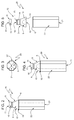
- Number 1 in Figure 1 indicates as a whole a semifinished composite container for pourable food products, which is obtained through the method according to the present invention starting from a rectangular or square sheet 2 of multilayer packaging material and a pouring part 3 made of plastic material.
- the multilayer packaging material of sheet 2 comprises a layer of fibrous material, e.g. paper, or of mineral-filled polypropylene material; a number of layers of heat-seal plastic material, e.g. polyethylene film; and a layer of gas- and light-barrier material, e.g. aluminium or ethyl vinyl alcohol (EVOH).
- fibrous material e.g. paper, or of mineral-filled polypropylene material
- heat-seal plastic material e.g. polyethylene film
- gas- and light-barrier material e.g. aluminium or ethyl vinyl alcohol (EVOH).
- container 1 is obtained by folding and sealing the sheet 2 to form a sleeve-like main portion 5 of axis A and by coaxially attaching the pouring part 3 to an upper end 6 of the main portion 5.
- the sheet 2 is folded so as to take a tubular or sleeve-like configuration and to overlap its opposite side edges 4a, 4b; the sheet 2 is then sealed along the overlapped edges 4a, 4b to form a longitudinal seal 7.
- edge 4a of sheet 2 is further provided with a sealing strip 8 made of heat-seal plastic material and which, in the sleeve-like configuration, is sealed on the inner faces of both edges 4a, 4b for preventing such edges from absorbing in use the food product and for improving the gas-barrier performance and physical strength of longitudinal seal 7.
- a sealing strip 8 made of heat-seal plastic material and which, in the sleeve-like configuration, is sealed on the inner faces of both edges 4a, 4b for preventing such edges from absorbing in use the food product and for improving the gas-barrier performance and physical strength of longitudinal seal 7.
- pouring part 3 basically comprises a pouring spout or neck 9, defining in use a pour opening 10 by which to pour the food product, and a cylindrical cap 11 fitted to the neck 9 in a removable way.
- Pouring part 3 may include a gas- and/or light-barrier and integrally defines a complete top portion 12 of container 1.
- Top portion 12 is produced, and attached to the main portion 5, in a closed configuration.
- An example of this kind of top portion is disclosed in WO 2008/148764 .
- neck 9 of top portion 12 has an inverted-cup shape and comprises an annular side wall 18 laterally bounding pour opening 10 and a disk-shaped top wall 19 closing pour opening on the side in which cap 11 is fitted to the neck 9 itself.
- side wall 18 of neck 9 has a bottom peripheral edge 13 adapted to be attached to upper end 6 of main portion 5 and a top end portion 14 provided with a thread 15 on its outer side surface.
- Cap 11 is produced in a single piece and is substantially defined by an annular cylindrical side wall 16, which has an internal thread (not visible in the enclosed Figures) for engaging the corresponding thread 15 of side wall 18 of neck 9, and by a disk-shaped top wall 17 for closing, in use, the top of the neck 9.
- Cap 11 is initially screwed completely onto neck 9 so that top wall 17 is superimposed on top wall 19 of neck 9.
- neck 9 has a weakening line (not visible in the enclosed Figures) between side wall 18 and top wall 19, and cap 11 is provided with means (also not visible in the enclosed Figures) for producing detachment of the top wall 19 from the side wall 18 upon removal of the cap 11 from the neck 9.
- neck 9 may be also produced in a completely open configuration (i.e. without top wall 19) and closed by cap 11.
- semifinished container 1 can be transformed in a finished container 20 by further not disclosed operations, including a filling operation to fill the container 1 with the pourable food product, a folding and sealing operation to form a flat bottom wall 21 orthogonal to axis A, and further folding operations to give the final appearance to main portion 5, which, in the example shown, comprises a side wall 22 having, in a bottom view (please see in particular Figure 3 ), an octagonal perimeter.
- the filling operation is performed on container 1 by introducing the product from the bottom side thereof, i.e. from the side opposite cap 11, before bottom wall 21 is formed and sealed.
- Semifinished composite container 1 is produced on a packaging machine 25 shown in Figure 6 and made in accordance with the teachings of the present invention.
- Machine 25 comprises a conveying device that serves to fold and seal a plurality of sheets 2 in the sleeve-like configuration and to produce attachment of a plurality of top portions 12 to the relative plurality of sheets 2.
- the conveying device comprises a carousel 26, which is mounted to rotate continuously (clockwise in Figure 6 ) about a respective vertical axis B.
- the carousel 26 receives a succession of top portions 12 from an input wheel 27, which cooperates with carousel 26 at a transfer station 28 and is mounted to rotate about a respective longitudinal axis C parallel to axis B.
- the rotation of the input wheel 27 is continuous and synchronized with the rotation of carousel 26.
- the carousel 26 also receives a succession of sheets 2 from an input device 29 (only schematically shown), which cooperates with carousel 26 at a transfer station 30; in particular, the sheets 2 are fed to the carousel 26 with their side edges 4a, 4b parallel to axis B and along a direction Z transversal to such axis.
- the carousel 26 releases a succession of semifinished containers 1 to an output wheel 31, which cooperates with carousel 26 at a transfer station 32 and is mounted to rotate about a respective longitudinal axis D parallel to axes B and C.
- the rotation of the output wheel 31 is continuous and synchronized with the rotation of carousel 26.
- the carousel 26 comprises a plurality of operating units 35, which are equally spaced about axis B, are mounted along a peripheral edge of carousel 26, and are moved by carousel 26 along a circular path P extending about axis B and through transfer stations 28, 30 and 32. As shown in Figure 6 , transfer station 30 is arranged, along path P, downstream of transfer station 28 and upstream of transfer station 32.
- the operating units 35 are secured to a horizontal rotary table 36 of carousel 26, have respective axes E parallel to axes B, C, D and extend coaxially through respective holes (not shown) of the rotary table 36 and on both sides of such table.
- operating unit 35 comprises:
- Forming member 38 can be moved along axis E by means of a cam and tappet device 40 (which will be described later in greater detail) to take a lowered position, a raised position and an intermediate position.
- a cam and tappet device 40 which will be described later in greater detail
- forming member 38 In the lowered position, forming member 38 is completely retracted within supporting mount 37, so that top surface 33 is substantially flush with a top surface of the supporting mount 37. In the intermediate position, forming member 38 protrudes from the top surface of the supporting mount 37 by a given value and is adapted to receive, on the outer surface 34 of its side wall 39, a sheet 2 from the input device 29. In the raised position, forming member 38 protrudes from the top surface of supporting mount 37 by a greater value than in the intermediate position.
- sheets 2 are cut in a know manner from a web (not shown) by a cutting device (known per se and not shown) and fed to the input device 29, which in turn feeds the sheets 2 to the carousel 26 with the respective sealing strips 8 arranged in a forward position.
- sheets 2 are fed by the input device 29, respectively, onto the outer surfaces 34 of the side walls 39 of the forming members 38, while the latter are located in the intermediate position.
- each forming member 38 is provided with a plurality of through holes 41, in turn connected to a pneumatic suction device (known per se and not shown), so as to retain the relative sheet 2 on its outer surface 34 by suction.
- a pneumatic suction device known per se and not shown
- each forming member 38 is rotated about the relative axis E in order to produce the complete wrapping of the relative sheet 2, coming from input device 29, on its outer surface 34.
- the rotation of the forming members 38 can be performed either in the same direction as the direction of rotation of carousel 26 about axis B (clockwise direction) or in the opposite direction (counter-clockwise direction).
- each sheet 2, fed by input device 29, is wrapped around the relative forming member 38 so as to form a cylinder with the vertical edge 4a superimposed on the vertical edge 4b, which is in turn interposed between the vertical edge 4a and part of the sealing strip 8.
- Suction portion 42 has an arc-shaped cross section along a plane orthogonal to axis E and is sized in the circumferential direction so as to cooperate with two portions of the relative sheet 2, which are adjacent, respectively, to the vertical edges 4a, 4b.
- suction portion 42 is divided into two distinct vertical regions 43, 44 by an elastically deformable, vertical strip pad 45, on which vertical edges 4a, 4b and sealing strip 8 of a relative sheet 2 are placed in an overlapped configuration.
- Strip pad 45 defines, in a known manner, the contrasting element for a relative sealing device 46 (only schematically shown in Figure 9 ), arranged in front of, and in a radially inner position than, side wall 39 of the relative forming member 38 and adapted to seal the overlapped edges 4a, 4b and the sealing strip 8 of the relative sheet 2 so as to produce a tubular configuration of such sheet.
- a relative sealing device 46 (only schematically shown in Figure 9 ), arranged in front of, and in a radially inner position than, side wall 39 of the relative forming member 38 and adapted to seal the overlapped edges 4a, 4b and the sealing strip 8 of the relative sheet 2 so as to produce a tubular configuration of such sheet.
- each sealing device 46 is carried in an upright position by the rotating table 36 and comprises:
- the sealing operation is carried out by electromagnetic induction; in practice, an electric current is induced in the barrier layer of the processed sheet 2 to heat it locally and so locally melt the heat-seal plastic material in the region to be sealed.
- each sealing device 46 includes an inductor 49, which defines the rectilinear striplike active working surface 48 and is supplied by a high-frequency current generator (known per se and not shown); by activating inductor 49, a longitudinal seal 7 is produced on the relative sheet 2 along edges 4a, 4b and sealing strip 8 so that the sheet 2 is transformed into the sleeve-like main portion 5 of a relative semifinished container 1.
- inductor 49 defines the rectilinear striplike active working surface 48 and is supplied by a high-frequency current generator (known per se and not shown); by activating inductor 49, a longitudinal seal 7 is produced on the relative sheet 2 along edges 4a, 4b and sealing strip 8 so that the sheet 2 is transformed into the sleeve-like main portion 5 of a relative semifinished container 1.
- the sealing operation may be carried out by simply heating a sealing element adapted to cooperate with the region of the sheet 2 to be sealed.
- the sealing operation may be carried out by using an ultrasonic sealing device.
- each forming member 38 during travel of the relative operating unit 35 along path P, is subjected to distinct movements in different operative steps of the packaging machine 25:
- each driving shaft 51 which is coaxial with the relative forming member 38, extends through the relative supporting mount 37 and has a top end coupled in a fixed position to a bottom end of such forming member 38. Therefore, each driving shaft 51 and the relative forming member 38 are axially and angularly fixed to one another, so that any displacement transmitted to the driving shaft 51 results in a corresponding displacement of the forming member 38.
- Rotation of each driving shaft 51 is synchronized with the feeding movements imparted to the sheets 2 by the input device 29 and with the rotation of the carousel 26 and is operated by an actuator 53 (schematically shown in Figure 7 ), which is carried by the carousel 26 itself.
- the cam and tappet device 40 comprises a cam device 54 ( Figure 8 ) and, for each operating unit 35, a relative cam follower 55, which is defined, in particular, by a roller located outside of the relative supporting mount 37 and mounted on an outer end portion 56 of a supporting pin 57, so as to be axially fixed and freely rotatable with respect to an axis F of the supporting pin 57.
- the latter extends radially with respect to axes B and E through a slot 58, which is made in a lateral wall of the relative supporting mount 37 on the outer side with respect to axis B, i.e. on the side opposite to the relative sealing device 46.
- the supporting pin 57 has an end portion 59 axially opposite to end portion 56 and fixed with respect to a collar 60.
- Collar 60 is coaxial with the relative driving shaft 51 and is coupled to the driving shaft 51 by means of bearings 62, so as to be angularly free from, and axially fixed with respect to, the driving shaft 51 itself.
- collar 60 has an outer lateral surface slidably coupled to the inner surface 63 of the relative supporting mount 37, so as to be axially guided between an upper position and a lower position.
- end portion 59 is coupled to collar 60 by means of an annular element 64, which is fastened to the relative supporting pin 57 and to a side portion of the relative collar 60, and is guided by the relative slot 58 in a direction parallel to axis E. Therefore, the slot 58 defines a constraint that prevents the collar 60 and the cam follower 55 from rotating about axis E. Therefore, any displacement transmitted to a cam follower 55 results in an axial displacement of the relative driving shaft 51 and forming member 38 between the lowered and raised positions.
- a spring 65 is provided inside each supporting mount 37 to push the relative collar 60 upwards and, therefore, avoid axial play during displacement of the relative cam follower 55.
- the cam device 54 comprises a cylindrical ring element 66, which is fixed and extends coaxially with axis B and along path P around the operating units 35 that are transferred by carousel 26.
- Ring element 66 has, on its radially inner surface 67, an annular groove or track 68 which is engaged by the cam followers 55 of operating units 35.
- track 68 Starting from transfer station 28 and proceeding along path P, track 68 comprises:
- machine 25 also comprises, for each operating unit 35, a further sealing device 80 for sealing the upper end 6 of the sleeve-like main portion 5 obtained from the relative sheet 2 to the peripheral edge 13 of the corresponding top portion 12.
- Each sealing device 80 basically comprises a substantially cylindrical casing 81 of axis E, protruding vertically from an upper rotary portion 82 of carousel 26, and an annular inductor 83 secured to the bottom end of casing 81 and supplied by a high-frequency current generator (known per se and not shown).
- the inductor 83 defines an annular striplike active working surface 84 interacting with the upper end 6 of the relative sleeve-like main portion 5 and the peripheral edge 13 of the corresponding top portion 12, when the relative forming member 38 is arranged in the raised position.
- Each sealing device 80 further comprises a positioning bar 85 coaxially housed within casing 81 and having a bottom tubular end 86 adapted to be engaged by cap 11 of the relative top portion 12.
- the sealing of a top portion 12 to the corresponding sleeve-like main portion 5 is obtained by displacing the relative forming member 38 to the raised position so that the cap 11 is received into the bottom tubular end 86 of the relative positioning bar 85 and the relative working surface 84 contacts the upper end 6 of the main portion 5; in this way, pressure is created and the sealing is performed by activating the inductor 83, which induces an electric current in the barrier layer of the sheet 2 so as to heat and locally melt the upper end 6 of the sheet 2 itself and the peripheral edge 13 of the top portion 12; in practice, by activating inductor 83, a circumferential, transversal seal 52 of axis E is produced between the sleeve-like main portion 5 and the corresponding top portion 12 so as to obtain the semifinished container 1.
- the sealing operation may be carried out by simply heating an annular sealing element adapted to interact with the upper end 6 of the sleeve-like main portion 5 obtained by a relative sheet 2 and to produce sealing of such end with the peripheral edge 13 of the corresponding top portion 12.
- the sealing operation may be carried out by using an ultrasonic sealing device.
- one sheet 2 is put into contact with the forming member 38 passing through such station by the input device 29; in particular, the sheet 2 is advanced towards the forming member 38 with its side edge 4a and its sealing strip 8 facing forward.
- the sheet 2 is wrapped around the outer surface 34 of lateral wall 39 of the forming member 38 and retained thereon. More specifically, the sheet 2 is bent to assume a tubular configuration with the opposite vertical edges 4a, 4b and the sealing strip 8 in overlapped configuration.
- the upper end 6 thereof overlaps the peripheral edge 13 of the top portion 12.
- the sheet 2 is ready to be sealed along the edges 4a, 4b and the sealing strip 8 by activation of the sealing device 46.
- the forming member 38 reaches a given angular position around its axis E so as to put the overlapped edges 4a, 4b and the sealing strip 8 of the sheet 2 in front of the working surface 48 of the sealing device 46.
- the sealing element 47 can then be displaced by the actuator 50 along direction X into a position, in which the working surface 48 contacts the outer edge 4a of the sheet 2.
- inductor 49 of sealing element 47 By activating inductor 49 of sealing element 47, an electric current is induced in the barrier layer of the sheet 2 to heat it in the region of the overlapped edges 4a, 4b and the sealing strip 8 and so locally melt the heat-seal plastic material thereof to obtain longitudinal seal 7.
- the sheet 2 is transformed into the sleeve-like main portion 5 of the semifinished container 1.
- the sealing element 47 is displaced to its beginning position along direction X, so detaching the working surface 48 from the main portion 5.
- rising ramp-shaped portion 70 of track 68 of cam device 54 moves the driving shaft 51 along axis F, so producing a corresponding translational movement of the forming member 38 towards the raised position.
- This movement causes engagement of top portion 12 into sealing device 80; in particular, cap 11 of top portion 12 is pressed against positioning bar 85 and the upper end 6 of main portion 5, superimposed on peripheral edge 13 of the top portion 12, is pressed against active working surface 84 of inductor 83.
- sealing device 46 by activating inductor 49, an electric current is induced in the barrier layer of the sheet 2 to heat it in the region overlapped to the peripheral edge 13 of top portion 12 and so locally melt the heat-seal plastic materials into contact with one another to obtain circumferential, transversal seal 52.
- descending ramp-shaped portion 72 of track 68 of cam device 54 causes the forming member 38 to be displaced into the lowered position within the relative supporting mount 37, so as to free the so formed semifinished composite container 1, which can be then released to the output wheel 31 at transfer station 32.
- the forming member 38 is then moved into the intermediate position as a result of engagement between the cam follower 55 and rising ramp-shaped portion 74 of track 68 of cam device 54; the forming member 38 is therefore ready to receive another top portion 12 and another sheet 2.
- the method and the machine 25 according to the present invention permit to produce, in a quick, rational, reliable and economical way, a composite container.
Landscapes
- Engineering & Computer Science (AREA)
- Mechanical Engineering (AREA)
- Making Paper Articles (AREA)
- Containers And Plastic Fillers For Packaging (AREA)
- Supplying Of Containers To The Packaging Station (AREA)
- Cartons (AREA)
Priority Applications (5)
| Application Number | Priority Date | Filing Date | Title |
|---|---|---|---|
| EP10176717.6A EP2428355B1 (de) | 2010-09-14 | 2010-09-14 | Verfahren und Maschine zur Herstellung eines Behälters, insbesondere eines Behälters für gießbare Lebensmittelprodukte |
| CN201180044010.XA CN103079804B (zh) | 2010-09-14 | 2011-08-23 | 用于生产容器尤其是供可灌装食品用的容器的方法和机器 |
| JP2013527536A JP5940067B2 (ja) | 2010-09-14 | 2011-08-23 | 容器を製造するための特に液体食品用の容器を製造するための方法および機械 |
| PCT/EP2011/064455 WO2012034833A1 (en) | 2010-09-14 | 2011-08-23 | A method and a machine for producing a container, in particular a container for pourable food products |
| US13/812,710 US20130123086A1 (en) | 2010-09-14 | 2011-08-23 | Method and a machine for producing a container, in particular a container for pourable food products |
Applications Claiming Priority (1)
| Application Number | Priority Date | Filing Date | Title |
|---|---|---|---|
| EP10176717.6A EP2428355B1 (de) | 2010-09-14 | 2010-09-14 | Verfahren und Maschine zur Herstellung eines Behälters, insbesondere eines Behälters für gießbare Lebensmittelprodukte |
Publications (2)
| Publication Number | Publication Date |
|---|---|
| EP2428355A1 true EP2428355A1 (de) | 2012-03-14 |
| EP2428355B1 EP2428355B1 (de) | 2016-01-27 |
Family
ID=43500029
Family Applications (1)
| Application Number | Title | Priority Date | Filing Date |
|---|---|---|---|
| EP10176717.6A Not-in-force EP2428355B1 (de) | 2010-09-14 | 2010-09-14 | Verfahren und Maschine zur Herstellung eines Behälters, insbesondere eines Behälters für gießbare Lebensmittelprodukte |
Country Status (5)
| Country | Link |
|---|---|
| US (1) | US20130123086A1 (de) |
| EP (1) | EP2428355B1 (de) |
| JP (1) | JP5940067B2 (de) |
| CN (1) | CN103079804B (de) |
| WO (1) | WO2012034833A1 (de) |
Cited By (4)
| Publication number | Priority date | Publication date | Assignee | Title |
|---|---|---|---|---|
| WO2015058934A1 (de) * | 2013-10-25 | 2015-04-30 | Robert Bosch Gmbh | Behälter, insbesondere für flüssigkeiten |
| WO2015150794A1 (en) * | 2014-04-04 | 2015-10-08 | 3 Boys Limited | Container comprising a paperboard outer shell |
| WO2019034351A1 (en) * | 2017-08-15 | 2019-02-21 | Tetra Laval Holdings & Finance S.A. | FEEDING DEVICE |
| EP3718915A1 (de) * | 2019-04-02 | 2020-10-07 | Tetra Laval Holdings & Finance S.A. | Falzwerkzeug sowie system und verfahren zum falzen eines verpackungsmaterials |
Families Citing this family (1)
| Publication number | Priority date | Publication date | Assignee | Title |
|---|---|---|---|---|
| CN114536865B (zh) * | 2022-03-31 | 2024-04-16 | 杜国锋 | 管状容器的端面封口装置及封口方法 |
Citations (9)
| Publication number | Priority date | Publication date | Assignee | Title |
|---|---|---|---|---|
| GB1255790A (en) * | 1967-12-11 | 1971-12-01 | Rovema Verpackungsmaschinen G | Improvements in or relating to the production of soft packagings |
| US4295838A (en) * | 1977-11-21 | 1981-10-20 | Phillips Petroleum Company | Method of producing cylindrical containers |
| US5324249A (en) * | 1992-08-28 | 1994-06-28 | Paper Machinery Corporation | Cup making machine |
| EP1197438B1 (de) | 1997-01-29 | 2004-03-10 | Tetra Laval Holdings & Finance SA | Verfahren zur Herstellung eines Behälters |
| US20050198924A1 (en) * | 2002-05-03 | 2005-09-15 | Paolo Benedetti | Method and packaging machine for producing sealed packages of pourable food products from precut blanks of sheet packaging material |
| EP1616800A2 (de) * | 2004-07-15 | 2006-01-18 | WB Will - Bake GmbH | Verpackung sowie Verfahren zur deren Herstellung |
| US20060021298A1 (en) * | 2003-04-09 | 2006-02-02 | Jacky Van Caeneghem | Device, installation and process for producing a package from a sheet of a flexible material and for filling it with a pulverulent or nonpulverulent product |
| US20080105698A1 (en) * | 2004-12-21 | 2008-05-08 | Massimo Paradiso | Flexible Container |
| WO2008148764A2 (en) | 2007-06-05 | 2008-12-11 | Sacmi Cooperativa Meccanici Imola Societa' Cooperativa | Closing means |
Family Cites Families (12)
| Publication number | Priority date | Publication date | Assignee | Title |
|---|---|---|---|---|
| US1991223A (en) * | 1931-08-17 | 1935-02-12 | Gen Electric | Packing machine |
| DE1204062B (de) * | 1964-03-26 | 1965-10-28 | Paper Machinery Corp | Vorrichtung zum Verschweissen der Laengsnaht eines um einen Dorn herumgelegten Behaeltermantels |
| US3579958A (en) * | 1969-08-15 | 1971-05-25 | Haskon Inc | Machine for forming, filling, and sealing containers |
| US3764425A (en) * | 1972-01-10 | 1973-10-09 | Milprint Inc | Apparatus and method for the manufacture of tubular containers |
| EP0011550A1 (de) * | 1978-11-10 | 1980-05-28 | Embadac S.A. | Verfahren und Maschine zum Bekleiden eines hülsenartigen Elements, insbesondere zum Bekleiden einer Schachtel |
| JPH04339753A (ja) * | 1991-05-08 | 1992-11-26 | Jujo Paper Co Ltd | 紙容器内部の包装材料端部保護テープ |
| JPH11236032A (ja) * | 1997-12-18 | 1999-08-31 | Dainippon Printing Co Ltd | 液体紙容器 |
| JP2000212528A (ja) * | 1999-01-27 | 2000-08-02 | Nihon Tetra Pak Kk | 包装容器内部の包装材料端部保護テ―プ及びその包装容器 |
| JP2005035591A (ja) * | 2003-07-18 | 2005-02-10 | Dainippon Printing Co Ltd | 紙カップおよびその製造方法 |
| JP2007269398A (ja) * | 2006-03-31 | 2007-10-18 | Sunstar Engineering Inc | 軟質容器及びその製造方法並びに内容物収容軟質容器 |
| ITBO20070034A1 (it) * | 2007-01-23 | 2008-07-24 | Emmeci S R L | Macchina e metodo per realizzare scatole da imballaggio curvilinee. |
| ATE554910T1 (de) * | 2009-10-27 | 2012-05-15 | Eha Spezialmaschb Gmbh | Ziehvorrichtung zum ziehen eines wickeldornes aus einem auf dem wickeldorn aufgewickelten wickelprodukt |
-
2010
- 2010-09-14 EP EP10176717.6A patent/EP2428355B1/de not_active Not-in-force
-
2011
- 2011-08-23 US US13/812,710 patent/US20130123086A1/en not_active Abandoned
- 2011-08-23 JP JP2013527536A patent/JP5940067B2/ja not_active Expired - Fee Related
- 2011-08-23 CN CN201180044010.XA patent/CN103079804B/zh not_active Expired - Fee Related
- 2011-08-23 WO PCT/EP2011/064455 patent/WO2012034833A1/en active Application Filing
Patent Citations (9)
| Publication number | Priority date | Publication date | Assignee | Title |
|---|---|---|---|---|
| GB1255790A (en) * | 1967-12-11 | 1971-12-01 | Rovema Verpackungsmaschinen G | Improvements in or relating to the production of soft packagings |
| US4295838A (en) * | 1977-11-21 | 1981-10-20 | Phillips Petroleum Company | Method of producing cylindrical containers |
| US5324249A (en) * | 1992-08-28 | 1994-06-28 | Paper Machinery Corporation | Cup making machine |
| EP1197438B1 (de) | 1997-01-29 | 2004-03-10 | Tetra Laval Holdings & Finance SA | Verfahren zur Herstellung eines Behälters |
| US20050198924A1 (en) * | 2002-05-03 | 2005-09-15 | Paolo Benedetti | Method and packaging machine for producing sealed packages of pourable food products from precut blanks of sheet packaging material |
| US20060021298A1 (en) * | 2003-04-09 | 2006-02-02 | Jacky Van Caeneghem | Device, installation and process for producing a package from a sheet of a flexible material and for filling it with a pulverulent or nonpulverulent product |
| EP1616800A2 (de) * | 2004-07-15 | 2006-01-18 | WB Will - Bake GmbH | Verpackung sowie Verfahren zur deren Herstellung |
| US20080105698A1 (en) * | 2004-12-21 | 2008-05-08 | Massimo Paradiso | Flexible Container |
| WO2008148764A2 (en) | 2007-06-05 | 2008-12-11 | Sacmi Cooperativa Meccanici Imola Societa' Cooperativa | Closing means |
Cited By (8)
| Publication number | Priority date | Publication date | Assignee | Title |
|---|---|---|---|---|
| WO2015058934A1 (de) * | 2013-10-25 | 2015-04-30 | Robert Bosch Gmbh | Behälter, insbesondere für flüssigkeiten |
| WO2015150794A1 (en) * | 2014-04-04 | 2015-10-08 | 3 Boys Limited | Container comprising a paperboard outer shell |
| EP3231730A1 (de) * | 2014-04-04 | 2017-10-18 | Frugalpac Limited | Behälter mit aussenhülle aus pappe |
| US10717578B2 (en) | 2014-04-04 | 2020-07-21 | Frugalpac Limited | Container comprising a paperboard outer shell |
| WO2019034351A1 (en) * | 2017-08-15 | 2019-02-21 | Tetra Laval Holdings & Finance S.A. | FEEDING DEVICE |
| EP3446990A1 (de) * | 2017-08-15 | 2019-02-27 | Tetra Laval Holdings & Finance S.A. | Vorschubvorrichtung und verfahren zum zuführen eines verpackungsmaterialzuschnitts |
| CN109398818A (zh) * | 2017-08-15 | 2019-03-01 | 利乐拉瓦尔集团及财务有限公司 | 一种进给装置 |
| EP3718915A1 (de) * | 2019-04-02 | 2020-10-07 | Tetra Laval Holdings & Finance S.A. | Falzwerkzeug sowie system und verfahren zum falzen eines verpackungsmaterials |
Also Published As
| Publication number | Publication date |
|---|---|
| WO2012034833A1 (en) | 2012-03-22 |
| JP2013541472A (ja) | 2013-11-14 |
| EP2428355B1 (de) | 2016-01-27 |
| US20130123086A1 (en) | 2013-05-16 |
| JP5940067B2 (ja) | 2016-06-29 |
| CN103079804B (zh) | 2016-01-20 |
| CN103079804A (zh) | 2013-05-01 |
Similar Documents
| Publication | Publication Date | Title |
|---|---|---|
| EP2428355B1 (de) | Verfahren und Maschine zur Herstellung eines Behälters, insbesondere eines Behälters für gießbare Lebensmittelprodukte | |
| CN101336159B (zh) | 将开启装置施加到可倾倒食品的包装品上的单元 | |
| JP4939549B2 (ja) | 注出可能な食品のパッケージに開封具を付けるためのモジュラー・ユニット | |
| US20110274527A1 (en) | Method for moving a reel of packaging material from a storage station to a supply station of a packaging unit for producing sealed packages of food product, and clamping unit for clamping such reel | |
| CN106457729A (zh) | 用于生产容器的包装材料的片材和用于生产容器的方法 | |
| CN107922061B (zh) | 一种用于封盖容器的设备 | |
| EP2782837B1 (de) | Verfahren zum versiegeln von metalldosen mit abziehbaren deckeln und dazugehörige vorrichtung | |
| CN102196965A (zh) | 用于将粘结剂施加到一连串开口装置上以便胶粘到可被灌注入包装材料管内的食品的密封包装上的胶粘单元 | |
| WO2015101492A1 (en) | An apparatus for forming opening devices on a sheet packaging material for packaging food products | |
| CN102245477A (zh) | 用于将开启装置应用在能灌装到包装材料管中的食品的包装上的单元 | |
| CN102216160B (zh) | 用于在装配到能灌装到包装材料管中的食品的包装上的开启装置上施加压力的加压装置 | |
| CN107921715A (zh) | 一种焊头 | |
| CN107922062B (zh) | 用于将盖施加于容器上的方法和施加头 | |
| EP1763434B1 (de) | Maschine zur herstellung von behältern für flüssigkeiten | |
| EP2781474B1 (de) | Einheit zum Transportieren und Aufrichten versiegelter Verpackungen mit gießbaren Lebensmittelprodukten | |
| RU2004135324A (ru) | Способ и упаковочная машина для производства запечатанных упаковок текучих пищевых продуктов из предварительно вырубленных заготовок из листового упаковочного материала | |
| JP2006501081A (ja) | 容器、特に食品用容器の成形システム | |
| EP3943400B1 (de) | Verpackungsformungseinheit, verpackungsvorrichtung mit einer verpackungsformungseinheit und verfahren zur formung von verpackungen | |
| EP4269267A2 (de) | Verpackungszuschnitt, verfahren zum formen einer deckelausgussanordnung auf einem verpackungszuschnitt, deckelausgussanordnung, verpackung mit deckelausgussanordnung und verfahren und vorrichtung zum formen eines verpackungszuschnitts | |
| EP4265533A1 (de) | Zuführförderer für eine falzvorrichtung, falzvorrichtung mit einem zuführförderer und verpackungsmaschine mit einer falzvorrichtung | |
| EP4269268A1 (de) | Verpackungszuschnitt und verpackung | |
| CN101020371A (zh) | 纸塑复合材料易拉罐的制造方法及制造设备 | |
| CN117083227A (zh) | 复合包装材料片材、形成复合包装材料片材的方法、复合包装和形成复合包装的方法 | |
| WO2017215940A1 (en) | Pressure unit | |
| JP2011246132A (ja) | 包装充填装置 |
Legal Events
| Date | Code | Title | Description |
|---|---|---|---|
| AK | Designated contracting states |
Kind code of ref document: A1 Designated state(s): AL AT BE BG CH CY CZ DE DK EE ES FI FR GB GR HR HU IE IS IT LI LT LU LV MC MK MT NL NO PL PT RO SE SI SK SM TR |
|
| AX | Request for extension of the european patent |
Extension state: BA ME RS |
|
| PUAI | Public reference made under article 153(3) epc to a published international application that has entered the european phase |
Free format text: ORIGINAL CODE: 0009012 |
|
| 17P | Request for examination filed |
Effective date: 20120905 |
|
| 17Q | First examination report despatched |
Effective date: 20121008 |
|
| RIC1 | Information provided on ipc code assigned before grant |
Ipc: B65D 8/00 20060101ALN20150130BHEP Ipc: B65D 3/04 20060101ALN20150130BHEP Ipc: B31B 3/32 20060101ALI20150130BHEP Ipc: B65D 3/22 20060101ALN20150130BHEP Ipc: B65D 3/26 20060101ALN20150130BHEP Ipc: B65D 3/20 20060101ALN20150130BHEP Ipc: B31B 1/84 20060101AFI20150130BHEP |
|
| GRAP | Despatch of communication of intention to grant a patent |
Free format text: ORIGINAL CODE: EPIDOSNIGR1 |
|
| INTG | Intention to grant announced |
Effective date: 20150611 |
|
| GRAS | Grant fee paid |
Free format text: ORIGINAL CODE: EPIDOSNIGR3 |
|
| GRAA | (expected) grant |
Free format text: ORIGINAL CODE: 0009210 |
|
| AK | Designated contracting states |
Kind code of ref document: B1 Designated state(s): AL AT BE BG CH CY CZ DE DK EE ES FI FR GB GR HR HU IE IS IT LI LT LU LV MC MK MT NL NO PL PT RO SE SI SK SM TR |
|
| REG | Reference to a national code |
Ref country code: GB Ref legal event code: FG4D |
|
| REG | Reference to a national code |
Ref country code: CH Ref legal event code: EP |
|
| REG | Reference to a national code |
Ref country code: AT Ref legal event code: REF Ref document number: 772493 Country of ref document: AT Kind code of ref document: T Effective date: 20160215 |
|
| REG | Reference to a national code |
Ref country code: IE Ref legal event code: FG4D |
|
| REG | Reference to a national code |
Ref country code: DE Ref legal event code: R096 Ref document number: 602010030306 Country of ref document: DE |
|
| REG | Reference to a national code |
Ref country code: LT Ref legal event code: MG4D |
|
| REG | Reference to a national code |
Ref country code: NL Ref legal event code: MP Effective date: 20160127 |
|
| REG | Reference to a national code |
Ref country code: AT Ref legal event code: MK05 Ref document number: 772493 Country of ref document: AT Kind code of ref document: T Effective date: 20160127 |
|
| PG25 | Lapsed in a contracting state [announced via postgrant information from national office to epo] |
Ref country code: NL Free format text: LAPSE BECAUSE OF FAILURE TO SUBMIT A TRANSLATION OF THE DESCRIPTION OR TO PAY THE FEE WITHIN THE PRESCRIBED TIME-LIMIT Effective date: 20160127 |
|
| PG25 | Lapsed in a contracting state [announced via postgrant information from national office to epo] |
Ref country code: GR Free format text: LAPSE BECAUSE OF FAILURE TO SUBMIT A TRANSLATION OF THE DESCRIPTION OR TO PAY THE FEE WITHIN THE PRESCRIBED TIME-LIMIT Effective date: 20160428 Ref country code: NO Free format text: LAPSE BECAUSE OF FAILURE TO SUBMIT A TRANSLATION OF THE DESCRIPTION OR TO PAY THE FEE WITHIN THE PRESCRIBED TIME-LIMIT Effective date: 20160427 Ref country code: ES Free format text: LAPSE BECAUSE OF FAILURE TO SUBMIT A TRANSLATION OF THE DESCRIPTION OR TO PAY THE FEE WITHIN THE PRESCRIBED TIME-LIMIT Effective date: 20160127 Ref country code: HR Free format text: LAPSE BECAUSE OF FAILURE TO SUBMIT A TRANSLATION OF THE DESCRIPTION OR TO PAY THE FEE WITHIN THE PRESCRIBED TIME-LIMIT Effective date: 20160127 Ref country code: FI Free format text: LAPSE BECAUSE OF FAILURE TO SUBMIT A TRANSLATION OF THE DESCRIPTION OR TO PAY THE FEE WITHIN THE PRESCRIBED TIME-LIMIT Effective date: 20160127 |
|
| REG | Reference to a national code |
Ref country code: FR Ref legal event code: PLFP Year of fee payment: 7 |
|
| PG25 | Lapsed in a contracting state [announced via postgrant information from national office to epo] |
Ref country code: AT Free format text: LAPSE BECAUSE OF FAILURE TO SUBMIT A TRANSLATION OF THE DESCRIPTION OR TO PAY THE FEE WITHIN THE PRESCRIBED TIME-LIMIT Effective date: 20160127 Ref country code: SE Free format text: LAPSE BECAUSE OF FAILURE TO SUBMIT A TRANSLATION OF THE DESCRIPTION OR TO PAY THE FEE WITHIN THE PRESCRIBED TIME-LIMIT Effective date: 20160127 Ref country code: LT Free format text: LAPSE BECAUSE OF FAILURE TO SUBMIT A TRANSLATION OF THE DESCRIPTION OR TO PAY THE FEE WITHIN THE PRESCRIBED TIME-LIMIT Effective date: 20160127 Ref country code: LV Free format text: LAPSE BECAUSE OF FAILURE TO SUBMIT A TRANSLATION OF THE DESCRIPTION OR TO PAY THE FEE WITHIN THE PRESCRIBED TIME-LIMIT Effective date: 20160127 Ref country code: PT Free format text: LAPSE BECAUSE OF FAILURE TO SUBMIT A TRANSLATION OF THE DESCRIPTION OR TO PAY THE FEE WITHIN THE PRESCRIBED TIME-LIMIT Effective date: 20160527 Ref country code: PL Free format text: LAPSE BECAUSE OF FAILURE TO SUBMIT A TRANSLATION OF THE DESCRIPTION OR TO PAY THE FEE WITHIN THE PRESCRIBED TIME-LIMIT Effective date: 20160127 Ref country code: IS Free format text: LAPSE BECAUSE OF FAILURE TO SUBMIT A TRANSLATION OF THE DESCRIPTION OR TO PAY THE FEE WITHIN THE PRESCRIBED TIME-LIMIT Effective date: 20160527 |
|
| REG | Reference to a national code |
Ref country code: DE Ref legal event code: R097 Ref document number: 602010030306 Country of ref document: DE |
|
| PG25 | Lapsed in a contracting state [announced via postgrant information from national office to epo] |
Ref country code: DK Free format text: LAPSE BECAUSE OF FAILURE TO SUBMIT A TRANSLATION OF THE DESCRIPTION OR TO PAY THE FEE WITHIN THE PRESCRIBED TIME-LIMIT Effective date: 20160127 Ref country code: EE Free format text: LAPSE BECAUSE OF FAILURE TO SUBMIT A TRANSLATION OF THE DESCRIPTION OR TO PAY THE FEE WITHIN THE PRESCRIBED TIME-LIMIT Effective date: 20160127 |
|
| REG | Reference to a national code |
Ref country code: DE Ref legal event code: R079 Ref document number: 602010030306 Country of ref document: DE Free format text: PREVIOUS MAIN CLASS: B31B0001840000 Ipc: B31B0050840000 |
|
| PG25 | Lapsed in a contracting state [announced via postgrant information from national office to epo] |
Ref country code: RO Free format text: LAPSE BECAUSE OF FAILURE TO SUBMIT A TRANSLATION OF THE DESCRIPTION OR TO PAY THE FEE WITHIN THE PRESCRIBED TIME-LIMIT Effective date: 20160127 Ref country code: SK Free format text: LAPSE BECAUSE OF FAILURE TO SUBMIT A TRANSLATION OF THE DESCRIPTION OR TO PAY THE FEE WITHIN THE PRESCRIBED TIME-LIMIT Effective date: 20160127 Ref country code: CZ Free format text: LAPSE BECAUSE OF FAILURE TO SUBMIT A TRANSLATION OF THE DESCRIPTION OR TO PAY THE FEE WITHIN THE PRESCRIBED TIME-LIMIT Effective date: 20160127 Ref country code: SM Free format text: LAPSE BECAUSE OF FAILURE TO SUBMIT A TRANSLATION OF THE DESCRIPTION OR TO PAY THE FEE WITHIN THE PRESCRIBED TIME-LIMIT Effective date: 20160127 |
|
| PLBE | No opposition filed within time limit |
Free format text: ORIGINAL CODE: 0009261 |
|
| STAA | Information on the status of an ep patent application or granted ep patent |
Free format text: STATUS: NO OPPOSITION FILED WITHIN TIME LIMIT |
|
| PG25 | Lapsed in a contracting state [announced via postgrant information from national office to epo] |
Ref country code: BE Free format text: LAPSE BECAUSE OF FAILURE TO SUBMIT A TRANSLATION OF THE DESCRIPTION OR TO PAY THE FEE WITHIN THE PRESCRIBED TIME-LIMIT Effective date: 20160127 |
|
| 26N | No opposition filed |
Effective date: 20161028 |
|
| PG25 | Lapsed in a contracting state [announced via postgrant information from national office to epo] |
Ref country code: SI Free format text: LAPSE BECAUSE OF FAILURE TO SUBMIT A TRANSLATION OF THE DESCRIPTION OR TO PAY THE FEE WITHIN THE PRESCRIBED TIME-LIMIT Effective date: 20160127 Ref country code: BG Free format text: LAPSE BECAUSE OF FAILURE TO SUBMIT A TRANSLATION OF THE DESCRIPTION OR TO PAY THE FEE WITHIN THE PRESCRIBED TIME-LIMIT Effective date: 20160427 |
|
| PG25 | Lapsed in a contracting state [announced via postgrant information from national office to epo] |
Ref country code: MC Free format text: LAPSE BECAUSE OF FAILURE TO SUBMIT A TRANSLATION OF THE DESCRIPTION OR TO PAY THE FEE WITHIN THE PRESCRIBED TIME-LIMIT Effective date: 20160127 |
|
| REG | Reference to a national code |
Ref country code: CH Ref legal event code: PL |
|
| GBPC | Gb: european patent ceased through non-payment of renewal fee |
Effective date: 20160914 |
|
| REG | Reference to a national code |
Ref country code: IE Ref legal event code: MM4A |
|
| PG25 | Lapsed in a contracting state [announced via postgrant information from national office to epo] |
Ref country code: IE Free format text: LAPSE BECAUSE OF NON-PAYMENT OF DUE FEES Effective date: 20160914 Ref country code: GB Free format text: LAPSE BECAUSE OF NON-PAYMENT OF DUE FEES Effective date: 20160914 Ref country code: CH Free format text: LAPSE BECAUSE OF NON-PAYMENT OF DUE FEES Effective date: 20160930 Ref country code: LI Free format text: LAPSE BECAUSE OF NON-PAYMENT OF DUE FEES Effective date: 20160930 |
|
| REG | Reference to a national code |
Ref country code: FR Ref legal event code: PLFP Year of fee payment: 8 |
|
| PG25 | Lapsed in a contracting state [announced via postgrant information from national office to epo] |
Ref country code: LU Free format text: LAPSE BECAUSE OF NON-PAYMENT OF DUE FEES Effective date: 20160914 |
|
| PG25 | Lapsed in a contracting state [announced via postgrant information from national office to epo] |
Ref country code: CY Free format text: LAPSE BECAUSE OF FAILURE TO SUBMIT A TRANSLATION OF THE DESCRIPTION OR TO PAY THE FEE WITHIN THE PRESCRIBED TIME-LIMIT Effective date: 20160127 Ref country code: HU Free format text: LAPSE BECAUSE OF FAILURE TO SUBMIT A TRANSLATION OF THE DESCRIPTION OR TO PAY THE FEE WITHIN THE PRESCRIBED TIME-LIMIT; INVALID AB INITIO Effective date: 20100914 |
|
| PG25 | Lapsed in a contracting state [announced via postgrant information from national office to epo] |
Ref country code: MK Free format text: LAPSE BECAUSE OF FAILURE TO SUBMIT A TRANSLATION OF THE DESCRIPTION OR TO PAY THE FEE WITHIN THE PRESCRIBED TIME-LIMIT Effective date: 20160127 Ref country code: TR Free format text: LAPSE BECAUSE OF FAILURE TO SUBMIT A TRANSLATION OF THE DESCRIPTION OR TO PAY THE FEE WITHIN THE PRESCRIBED TIME-LIMIT Effective date: 20160127 Ref country code: MT Free format text: LAPSE BECAUSE OF NON-PAYMENT OF DUE FEES Effective date: 20160930 |
|
| REG | Reference to a national code |
Ref country code: FR Ref legal event code: PLFP Year of fee payment: 9 |
|
| PG25 | Lapsed in a contracting state [announced via postgrant information from national office to epo] |
Ref country code: AL Free format text: LAPSE BECAUSE OF FAILURE TO SUBMIT A TRANSLATION OF THE DESCRIPTION OR TO PAY THE FEE WITHIN THE PRESCRIBED TIME-LIMIT Effective date: 20160127 |
|
| PGFP | Annual fee paid to national office [announced via postgrant information from national office to epo] |
Ref country code: FR Payment date: 20180813 Year of fee payment: 9 Ref country code: DE Payment date: 20180904 Year of fee payment: 9 Ref country code: IT Payment date: 20180919 Year of fee payment: 9 |
|
| REG | Reference to a national code |
Ref country code: DE Ref legal event code: R119 Ref document number: 602010030306 Country of ref document: DE |
|
| PG25 | Lapsed in a contracting state [announced via postgrant information from national office to epo] |
Ref country code: DE Free format text: LAPSE BECAUSE OF NON-PAYMENT OF DUE FEES Effective date: 20200401 |
|
| PG25 | Lapsed in a contracting state [announced via postgrant information from national office to epo] |
Ref country code: IT Free format text: LAPSE BECAUSE OF NON-PAYMENT OF DUE FEES Effective date: 20190914 |
|
| PG25 | Lapsed in a contracting state [announced via postgrant information from national office to epo] |
Ref country code: FR Free format text: LAPSE BECAUSE OF NON-PAYMENT OF DUE FEES Effective date: 20190930 |