EP2428271B1 - Pipette pour un système de pipetage avec pipette et seringue - Google Patents
Pipette pour un système de pipetage avec pipette et seringue Download PDFInfo
- Publication number
- EP2428271B1 EP2428271B1 EP11005349.3A EP11005349A EP2428271B1 EP 2428271 B1 EP2428271 B1 EP 2428271B1 EP 11005349 A EP11005349 A EP 11005349A EP 2428271 B1 EP2428271 B1 EP 2428271B1
- Authority
- EP
- European Patent Office
- Prior art keywords
- pipette
- plunger
- syringe
- gripping
- plunger head
- Prior art date
- Legal status (The legal status is an assumption and is not a legal conclusion. Google has not performed a legal analysis and makes no representation as to the accuracy of the status listed.)
- Active
Links
Images


Classifications
-
- B—PERFORMING OPERATIONS; TRANSPORTING
- B01—PHYSICAL OR CHEMICAL PROCESSES OR APPARATUS IN GENERAL
- B01L—CHEMICAL OR PHYSICAL LABORATORY APPARATUS FOR GENERAL USE
- B01L3/00—Containers or dishes for laboratory use, e.g. laboratory glassware; Droppers
- B01L3/02—Burettes; Pipettes
- B01L3/021—Pipettes, i.e. with only one conduit for withdrawing and redistributing liquids
- B01L3/0217—Pipettes, i.e. with only one conduit for withdrawing and redistributing liquids of the plunger pump type
-
- G—PHYSICS
- G01—MEASURING; TESTING
- G01F—MEASURING VOLUME, VOLUME FLOW, MASS FLOW OR LIQUID LEVEL; METERING BY VOLUME
- G01F1/00—Measuring the volume flow or mass flow of fluid or fluent solid material wherein the fluid passes through a meter in a continuous flow
- G01F1/76—Devices for measuring mass flow of a fluid or a fluent solid material
- G01F1/78—Direct mass flowmeters
- G01F1/80—Direct mass flowmeters operating by measuring pressure, force, momentum, or frequency of a fluid flow to which a rotational movement has been imparted
- G01F1/84—Coriolis or gyroscopic mass flowmeters
- G01F1/845—Coriolis or gyroscopic mass flowmeters arrangements of measuring means, e.g., of measuring conduits
- G01F1/8468—Coriolis or gyroscopic mass flowmeters arrangements of measuring means, e.g., of measuring conduits vibrating measuring conduits
-
- B—PERFORMING OPERATIONS; TRANSPORTING
- B01—PHYSICAL OR CHEMICAL PROCESSES OR APPARATUS IN GENERAL
- B01L—CHEMICAL OR PHYSICAL LABORATORY APPARATUS FOR GENERAL USE
- B01L2200/00—Solutions for specific problems relating to chemical or physical laboratory apparatus
- B01L2200/04—Exchange or ejection of cartridges, containers or reservoirs
-
- B—PERFORMING OPERATIONS; TRANSPORTING
- B01—PHYSICAL OR CHEMICAL PROCESSES OR APPARATUS IN GENERAL
- B01L—CHEMICAL OR PHYSICAL LABORATORY APPARATUS FOR GENERAL USE
- B01L2200/00—Solutions for specific problems relating to chemical or physical laboratory apparatus
- B01L2200/08—Ergonomic or safety aspects of handling devices
- B01L2200/087—Ergonomic aspects
-
- B—PERFORMING OPERATIONS; TRANSPORTING
- B01—PHYSICAL OR CHEMICAL PROCESSES OR APPARATUS IN GENERAL
- B01L—CHEMICAL OR PHYSICAL LABORATORY APPARATUS FOR GENERAL USE
- B01L3/00—Containers or dishes for laboratory use, e.g. laboratory glassware; Droppers
- B01L3/02—Burettes; Pipettes
- B01L3/021—Pipettes, i.e. with only one conduit for withdrawing and redistributing liquids
- B01L3/0217—Pipettes, i.e. with only one conduit for withdrawing and redistributing liquids of the plunger pump type
- B01L3/0227—Details of motor drive means
-
- B—PERFORMING OPERATIONS; TRANSPORTING
- B01—PHYSICAL OR CHEMICAL PROCESSES OR APPARATUS IN GENERAL
- B01L—CHEMICAL OR PHYSICAL LABORATORY APPARATUS FOR GENERAL USE
- B01L3/00—Containers or dishes for laboratory use, e.g. laboratory glassware; Droppers
- B01L3/02—Burettes; Pipettes
- B01L3/021—Pipettes, i.e. with only one conduit for withdrawing and redistributing liquids
- B01L3/0217—Pipettes, i.e. with only one conduit for withdrawing and redistributing liquids of the plunger pump type
- B01L3/0234—Repeating pipettes, i.e. for dispensing multiple doses from a single charge
Definitions
- the invention relates to a pipette for a pipette system with pipette and syringe, namely a pipette having the features of the preamble of claim 1.
- the known pipette, from which the invention proceeds ( DE 199 17 947 A1 ), is particularly suitable within a pipette system in terms of handling, because the interchangeable syringe to be handled in each case with the pipette can be inserted axially into the pipette and removed again from it or can be ejected therefrom.
- the respective syringe can therefore be inserted in a pure axial movement directly into the gripping positions of the flange of the cylinder and the piston head of the piston into the pipette.
- the fixation in the gripping position is effected by radially deliverable Zylindergreifhebel the Zylindergreif adopted to the mounting portion of the cylinder, ie its flange, and by radially deliverable piston gripping lever of the piston gripping device on the axially adjustable piston adjusting device.
- the syringe may be held stationary for receiving, for example, in a stand.
- the pipette must be moved axially relative to the syringe.
- To drop the syringe you also do not touch the syringe, it can simply fall out of the pipette axially or be dropped. The syringe is not touched, so that no contamination of the hand with the pipetted liquid can take place.
- the teaching is based on the problem of improving the initially described known pipette with axial syringe coupling with regard to the design and handling-related design options.
- the actuating device for the piston gripping device is attached to the axially displaceable piston adjusting device and can be axially displaced therewith in the pipette housing.
- a preferred embodiment of the teaching is the subject of claim 2.
- the piston head gripper by actuation of the actuator not only from the piston head releasing release position in the piston head on the piston actuator fixing gripping position adjustable, but also vice versa brought back into the release position. It is thus possible to hold the piston head in a force-locked manner in a controlled manner and to release it again.
- the piston gripping device is constructed in a special way.
- the piston grasper has a piston head of a syringe inserted into the pipette housing, transverse to the longitudinal axis of the pipette housing, d. H. radially, supporting support and a piston head gripper, which is adjustable relative to the piston head between a release the piston head release position and a common with the support the piston head to the piston adjusting device fixing gripping position.
- This piston head gripper fixes in the gripping position the piston head on the piston adjusting device in the axial direction slip-free.
- He is also adjustable by means of the actuating device in an at least one significant radial component having adjustment relative to the support.
- such an adjusting movement is realized in that the piston head gripper is pivotally mounted on the piston adjusting device. The radial component of the adjustment changes in the course of the pivoting of the piston head gripper against the support.
- the piston adjusting device therefore does not have the known from the prior art, oppositely positioned and radially deliverable piston gripping lever, but now the piston head gripper and as an abutment for the feed movement, the radially acting support on the piston adjusting device. In the gripping position creates a radially initiated clamping force without other components. It is generated directly by the one piston head gripper.
- the piston head gripper is designed in one piece in an advantageous embodiment.
- the essential part of the piston gripping device has been moved into the adjustable piston head gripper which is collision-free in the release position when the piston head of the syringe to be coupled is inserted axially into the pipette housing and the piston gripping device located therein.
- the radially supporting support which serves as an abutment for the piston head gripper, is arranged so that the piston head of the syringe to be coupled can be inserted axially without collision.
- a particularly useful structural configuration results from claim 3 with the specified additional stop.
- This stop acts as a kind of hold-down for the piston head, so that the piston head gripper can solve on the way to the release position of the piston head and this does not lift up under the effect of adhesion.
- the piston adjusting device expediently has an axially compressing pressure piece. At this an axially aligned stop surface is preferably arranged, which axially supports the piston head of a syringe inserted into the pipette housing.
- the stop which has the function of a hold-down, is suitably arranged on the pressure piece.
- the pressure piece is axially biased against the piston head and thus takes a syringe without a front position and with an inserted syringe a rear position.
- This is in principle the function of the solutions of the prior art.
- the pressure piece blocked in its forward position, the piston gripping device, so that the piston head gripper is then not adjustable in the gripping position. Without syringe so the piston head gripper can not be activated. This can prevent a syringe from being used when the piston head gripper is closed. Improper handling of the pipette is thus prevented.
- the movement sequence for the actuating device is optimized by the radial adjustment movement of the actuating device relative to the piston adjusting device according to claim 5, in particular if one chooses the variant with the superimposed pivoting movement about a transverse pivot axis.
- This initially transverse to the axial guidance of the piston adjusting device extending adjustment allows it together with a slotted guide to use the actuator both for driving the piston head gripper and for actuating the piston adjusting device and thus the piston of the syringe.
- the axial coupling should be as easy as possible. This can be done according to designed and arranged chamfers on the support and also on the stop. This facilitates the manual assembly of pipette and syringe.
- at least one cylinder gripping lever pivotably mounted in the pipette housing is realized according to the preferred teaching, as is the subject matter of claim 8. An automatic coupling when assembling the pipette and syringe is possible.
- the actuator can also be used to operate the Zylindergreif raised. This is the subject of claim 9. Particular constructive embodiments of this coupled embodiment are the subject matter of claims 10 to 13.
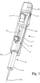
- Fig. 1 shows the basic design of a pipette 1 according to the invention with a syringe 2 inserted.
- the pipette 1 is driven with respect to the operation of the syringe 2 in operation by means of a button 3.
- An adjustment 4 allows adjustment of the stroke per key stroke.
- the syringe 2 is typically made of plastic material and has a cylinder 5 with a mounting portion 6 and a running in the cylinder 5 piston 7 with a piston head 8.
- the syringe 2 itself is manageable and interchangeable, The each with the pipette 1 to be handled, replaceable syringe 2 can at the in Fig. 1 shown pipette 1 axially inserted into the pipette and also axially removed from this or discarded by this.
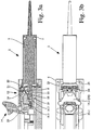
- FIGS. 2 to 7 each show the axially lower end of the pipette 1 Fig. 1 , To the implemented there mechanics is in the present invention.
- a longitudinal section is shown at this point, in the second part of the figure (b) then a plan view at this point.
- Fig. 1 combined with Fig. 2 can be seen first that the attachment portion 6 of the cylinder 5 is here and preferably designed as an annular flange. On the piston 7 there is a piston 7 which is also inserted completely into the cylinder 5 (FIG. Fig. 2 One recognizes this also particularly well with removed syringe 2, the in Fig. 4 is shown.
- the pipette 1 has a pipette housing 9, which has a longitudinal axis 10.
- the syringe 2 is inserted into the pipette housing 9 at a local axial opening 9.1 so that it is aligned in the direction of the longitudinal axis 10.
- all directions refer to the longitudinal axis 10.
- the term "axial” means "in the direction of the longitudinal axis 10", but includes lines parallel to the longitudinal axis 10 itself. In Fig. 1 the arrow A shows the axial Direction also visually.
- the term "radial” means an orientation transverse to the longitudinal axis 10 of the pipette housing 9 or corresponding to the longitudinal axis 10 of parallel lines.
- Genus of the present invention is therefore a pipette 1 with axially coupled or ejectable syringe 2.
- the axially accessible opening 9.1 on the pipette housing 9 can also be seen in Fig. 2a and in all other figures.
- Fig. 2 shows an axially accessible, in the pipette housing 9 fixedly mounted Zylindergreif adopted 11 for the attachment portion 6 of the syringe.
- Fig. 2a / b shows how the mounting portion 6 is held with the Zylindergreif observed 11.
- a piston adjusting device 12 is provided axially displaceable in the pipette housing 9.
- the piston actuator 12 is driven by actuating the button 3 to eject portions of liquid from the syringe 2.
- a piston gripping device 13 is mounted for the piston head 8 of the syringe 2, which is axially accessible and axially displaceable with the piston adjusting device 12 in the pipette housing 9.
- An actuating device 14 for the piston gripping device 13 is located on the piston adjusting device 12.
- the piston gripping device 13 is actuated by actuating the actuating device 14 from a gripping position, Fig. 2 in a release position, Fig. 3 , can be brought, in which the piston head 8 of a syringe 2 is released for removal or recording.
- the piston adjusting device 12 is in the illustrated embodiment also for moving in the axial direction, mainly for sucking liquid, driven by the actuator 14. It can be seen in the pipette housing 9, an opening 9.2 for the actuator 14 of the piston adjusting device 12. For sucking liquid into the syringe 2 into it the actuator 14 in Fig. 1 pushed on the pipette housing 9 in the direction of arrow A up to the upper stop formed by the opening 9.2. The downward movement for dispensing subsets then takes place by pressing the key 3 in individual stages.
- actuating device 14 for the piston gripping device 13 is attached to the piston adjusting device 12 and is axially displaceable therewith, like this Fig. 1 already showed.
- the actuating device 14 is therefore not, as in the prior art described at the beginning, disconnected from the piston adjusting device 12 when working with the pipette 1. This has the advantages mentioned in the general part of the description.
- the piston gripping device 13 can be brought by pressing the actuator 14 from the release position into the gripping position that the piston gripper 13 a piston head 8 inserted into the pipette 9 syringe 2 transverse to the longitudinal axis 10 of the pipette housing 9, ie radially , supporting support 15 and an adjustable piston head gripper 16, that the piston head gripper 16 by actuating the actuator 14 from the piston head 8 releasing release position in the piston head 8 at the piston actuator 12 fixing gripping position is adjustable and that the piston head gripper 16 by means of the actuator 14 in an adjustment movement having at least one significant radial component relative to the support 15 is adjustable.
- the piston head gripper 16 is pivotally mounted on the piston adjusting device 12.
- the radial component of the adjustment changes during the adjustment of the piston head gripper 16. It is getting bigger, the closer the piston head gripper 16 of the support 15 comes.
- Fig. 2 are up in Fig. 2a in longitudinal section and below in Fig. 2b shown in plan view, the components of the pipette 1 in gripping position.
- the piston head gripper 16 is by means of the actuator 14 in a significant radial component having adjusting movement relative to the support 15 has been adjusted down into the gripping position.
- the actuator is equipped with a stable operating lever 17.
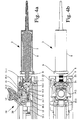
- Fig. 3 is the open, located in the release position piston head gripper 16 is shown.
- the actuator 14 is to from Fig. 2 to Fig. 3 in the in Fig. 3a shown level has been pivoted to the right. It can be seen that the piston head gripper 16 in Fig. 3a across from Fig. 2a has been raised.
- the piston head gripper 16 was pivoted about an axis 16.2 on the piston adjusting device 12.
- the piston head 8 is now released and could, if desired, be pulled out of the pipette housing 9 to the right.
- piston head gripper 16 is made in one piece, in a sense as a U-shaped body. In principle, however, the piston head gripper 16 could also be made up of several components.
- FIG. 3a shows that by means of the stop 18 on the piston adjusting device 12, the piston head 8 is held down on the support 15, although the piston head gripper 16 has been pulled off upwards.
- the stopper 18 thus acts as a kind of hold-down.
- Fig. 2 and 3 also show that the piston adjusting device 12 has an axially compressing thrust piece 19.
- This axially einfedernde thrust piece 19 is by a compression spring 19.1 in Fig. 2 and 3 biased to the right, so that when inserted syringe 2, the piston 7 has been advanced safely to the bottom of the cylinder 5.
- an insertion bevel 19.2 is located on the pressure piece 19 and an axially aligned stop surface 19.3, which axially supports the piston head 8 of an inserted into the pipette housing 9 syringe 2 and thus fulfills the previously described feed function.
- the stop 18 is arranged on the pressure piece 19.
- the pressure piece 19 thus combines the axial feed function with the hold-down function for the piston head eighth
- FIG. 3a A comparison of Fig. 3a and Fig. 4a makes clear that the pressure piece 19 is axially biased against the piston head 8 of the syringe 2 to be inserted axially by means of the compression spring 19.1 and thus without syringe 2 (FIG. Fig. 4a ) a front and with an inserted syringe 2 ( Fig. 2a . 3a ) occupies a rear, deeper in the pipette housing 9 lying position.
- the axial displacement movement of the pressure element 19 under the action of the compression spring 19.1 can be used to control the piston gripping device 13.
- the pressure piece 19 blocks the piston gripping device 13 in its forward position, so that the piston head gripper 16 is not adjustable in the gripping position, and in the rear position, the piston gripper 13 releases, so that Piston head gripper 16 is adjustable in the gripping position.
- actuating device 14 is attached to the piston adjusting device 12 in such a way that it is suitable for the adjustment of the piston head gripper 16 from the gripping position into the release position is radially displaceable and optionally additionally pivotable about a pivot axis 20 extending both transversely to the longitudinal axis 10 and transverse to the direction of displacement.
- the actuating device 14 or the actuating lever 17 of the actuating device 14, is pivotable about the pivot axis 20 extending both transversely to the longitudinal axis and transversely to the direction of displacement. It can be seen that the pivot axis 20 is radially displaceable or adjustable. This can be seen in the comparison of Fig. 2a to Fig. 3a and Fig. 4a , The pivot axis 20 has moved in the slot of the piston gripping device 12 from bottom to top. So you have here a superimposed sliding movement and pivotal movement about the pivot axis 20th
- Fig. 3 and 4 let recognize on the piston head gripper 16 that here laterally arranged clamping jaws 21 are provided, which can preferably transmit lateral clamping and axially considerable tensile forces from the piston adjusting device 12 to the piston.
- the clamping jaws 21 with profilings 22 (FIG. Fig. 3a ), which hold the piston head 8 positively and / or non-positively.
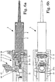
- profilings 22 (FIG. Fig. 3a ), which hold the piston head 8 positively and / or non-positively.
- Particularly preferred are blade-like profiles. These blade-like profiles can be designed in the form of cutting rollers. You can also connect fixed cutting-like profilings on the one hand with cutter rollers on the other.
- the profiles 22 are, viewed in gripping position, arranged so that they are not equal to the center line of the piston head 8 of the syringe 2. So they are slightly oblique, as it were skewed and possibly also arranged offset to the longitudinal axis 10 extending.
- the actuation force for the piston head gripper 16 is less than if the profilings 22 were arranged in the gripping position exactly in the direction of the longitudinal axis 10.
- the piston head gripper 16 From there, the piston head gripper 16 from there by a pivoting of the actuator 14 and the actuating lever 17 to the left of the in Fig. 3a shown release position in the in Fig. 2a shown Brought gripping position.
- the piston head gripper 16 is pivoted with its laterally arranged clamping jaws 21 with the profilings 22 in the direction of the radially supporting support 15 under high expenditure of force with a considerable radial movement component.
- the piston head 8 is supported on the support 15 so as to be fixed on an abutment.
- the jaws 21 engage the piston head 8 in the gripping position so that it is fixed with respect to the piston adjusting device 12 in the axial direction and so the piston 7 can be moved by adjusting the piston adjusting device 12 in the cylinder 5.
- the piston head gripper 16 generates in the gripping position with its in this embodiment U-shaped body and the laterally arranged jaws 21, the clamping force on the piston head 8 without known from the prior art linkage or spring support.
- the piston head gripper 16 is made in one piece. In principle, it would also be possible to construct the piston head gripper 16 in several parts.
- the profilings 22 on the clamping jaws 21 can be formed directly on the material of the piston head gripper 16.
- An alternative consists in separate cutting rollers as profiles 22.
- Such cutting rollers can be made of relatively hard material, such as steel or hard plastic and are then inserted into the jaws 21.
- the pressure piece 19 has an insertion bevel 19.2 in order to facilitate the axial insertion of the piston head 8 of the syringe 2.
- a corresponding insertion bevel 12.1 can also be provided on the support 15, which is formed on the piston adjusting device 12. Is in Fig. 4a been identified.
- chamfers are integrally formed on the jaws 21 of the piston head gripper 16.
- Fig. 2 . 3 and 4 make clear in their sequence that the actuating device 14 or its actuating lever 17 for adjusting the piston head gripper 16 from the gripping position to the release position a pivotal movement forward, ie in the direction of the syringe 2, and that for adjusting the Zylindergreif worn 11 from the gripping position in the release position continues this pivotal movement forward.
- the continuation of the swing movement can be seen in the transition from Fig. 3a to Fig. 4a , This sequence of movements corresponds to an intuitively expedient movement of the actuating device 14.
- Fig. 8 For the sequence of movements of the actuator 14 and its actuating lever 17 is on Fig. 8 Reference is made, which shows an enlarged view here. That's one way to realize such a construction.
- a link 27 with a run-on slope 28 is found on the piston adjusting device 12.
- the actuating lever 17 is seated with its lower arm 17 'normally under the spring force of a spring element 14.1 on the run-on slope 28.
- the spring element 14.1 a leg spring pushes with its horizontal, supporting leg, the pivot axis 20 and the actuating lever 17 down.
- a defined position of the actuating lever 17 of the actuating device 14 is predetermined ( Fig. 8a ).
- the spring element 14.1 acts in the direction of the pivoting movement for adjusting the piston head gripper 16 from the gripping position to the release position.
- Fig. 8b shows that in this position, that is the Fig. 3 corresponding position of the actuating device 14, the spring element 14.1 abuts an elevated stop surface below the gate 27.
- the actuating lever 17 of the actuator 14 is further pivoted clockwise, ie in the direction of the position in Fig. 8c , so the position of the pivot axis 20 is no longer radially changed (determined by the slot of the piston adjusting device 12, the in Fig. 2 to 4 is shown).
- the actuator 14 pivots on, but now with neutralized for the pivoting movement spring element 14.1.
- the spring element 14.1 is so far ineffective that only the frictional force between the lower arm 17 'and the gate 27 acts.
- Fig. 4 shows the syringe 2 right away from the pipette housing 9 to indicate that you can separate the syringe 2 in this position from the pipette housing 9 or insert it axially.
- Fig. 1 combined with Fig. 2 to 4 also makes clear that it is provided that the pipette 1 has a cover 25 for closing an opening 9.2 in the pipette housing 9 for the actuator 14 of the piston actuator 12 and that the cover 25 forms the power transmission train 14.2. This can be seen in particular below Fig. 2b ,
- Fig. 5 . 6 and 7 show in a corresponding representation as the first embodiment according to Fig. 2 . 3 . 4 a second, also expedient embodiment of the teaching of the invention.
- an additional actuating slide 26 is arranged for actuating the Zylindergreif Vietnamese 11.
- the actuating slide 26 symmetrically opens the Zylindergreifhebel 23 of the Zylindergreif adopted 11 via the drive arms 24.
- the control of the piston head gripper 16 is effected by the actuating lever 17 of the actuator 14.
- the sequence as in the first embodiment when the transition from Fig. 5 to Fig. 6 considered.
- the actuating slide 26 is a projection 26.1, which engages the drive arms 24 of the Zylindergreifhebel 23 and presses them in the direction of the syringe 2, so that the Zylindergreifhebel 23 open and the attachment portion 6 of the syringe 2 release.
- the arrow 26.2 in Fig. 7a indicates the direction of actuation for this actuation function.
Landscapes
- Physics & Mathematics (AREA)
- Fluid Mechanics (AREA)
- General Physics & Mathematics (AREA)
- Health & Medical Sciences (AREA)
- Clinical Laboratory Science (AREA)
- Chemical & Material Sciences (AREA)
- Chemical Kinetics & Catalysis (AREA)
- Sampling And Sample Adjustment (AREA)
- Devices For Use In Laboratory Experiments (AREA)
Claims (15)
- Pipette- destinée à un système de pipetage constitué d'une pipette (1) et d'une seringue (2), dans laquelle la seringue (2) comporte un cylindre (5) muni d'une section de fixation (6) de préférence réalisée sous la forme d'une bride et un piston (7) muni d'une tête de piston (8) faisant également saillie par l'extrémité hors du cylindre (5) lorsque le piston (7) est entièrement inséré dans le cylindre (5),
comportant un boîtier de pipette (9) qui présente un axe longitudinal (10),- dans lequel une seringue (2) devant être manipulée à l'aide de la pipette (1) peut être insérée au moyen de sa section de fixation (6) et de la tête de piston (8) dans la direction de l'axe longitudinal (10) du boîtier de pipette (9), c'est-à-dire axialement dans le boîtier de pipette (9) et en être retirée ou en être expulsée, comportant une ouverture (9.1) accessible axialement sur le boîtier de pipette (9) pour la section de fixation (6) d'une seringue (2),
comportant un dispositif de saisie de cylindre (11) accessible axialement et pouvant être monté en position fixe dans le boîtier de pipette (9), pour la section de fixation (6) d'une seringue (2),
comportant un dispositif de réglage de piston (12) pouvant être déplacé axialement dans le boîtier de pipette (9),
comportant un dispositif de saisie de piston (13) accessible axialement destiné à la tête de piston (8) d'une seringue (2), pouvant être monté sur le dispositif de réglage de piston (12) et pouvant être déplacé axialement avec celui-ci, et
comportant un dispositif d'actionnement (14) destiné au dispositif de saisie de piston (13),
dans lequel le dispositif de saisie de piston (13) peut être amené à passer d'une position de saisie à une position de libération à laquelle la tête de piston (8) d'une seringue (2) est libérée pour en être retirée ou y être reçue, par actionnement du dispositif d'actionnement (14),
caractérisée en ce que le dispositif d'actionnement (14) destiné au dispositif de saisie de piston (13) est monté sur le dispositif de réglage de piston (12) et peut être déplacé axialement avec celui-ci. - Pipette selon la revendication 1, caractérisée en ce que le dispositif de saisie de piston (13) peut également être amené à passer de la position de libération à la position de saisie par actionnement du dispositif d'actionnement (14),
en ce que le dispositif de saisie de piston (13) comporte un support (15) supportant radialement la tête de piston (8) d'une seringue (2) insérée dans le boîtier de pipette (9) transversalement à l'axe longitudinal (10) du boîtier de pipette (9) et un élément de saisie de tête de piston (16) réglable,
en ce que l'élément de saisie de tête de piston (16) peut être réglé par actionnement du dispositif d'actionnement (14) pour passer de la position de libération libérant la tête de piston (8) à la position de saisie fixant la tête de piston (8) sur le dispositif de réglage de piston (12), et
en ce que l'élément de saisie de tête de piston (16) peut être réglé au moyen du dispositif d'actionnement (14) de manière à effectuer un mouvement de réglage présentant au moins une composante radiale notable par rapport au support (15),
dans lequel l'élément de saisie de tête de piston (16) est à cet effet de préférence monté de manière pivotante sur le dispositif de réglage de piston (12). - Pipette selon la revendication 2,
caractérisée en ce que le dispositif de réglage de piston (12) comporte une butée (18) qui supporte la tête de piston (8) d'une seringue (2) insérée dans le boîtier de pipette (9) dans une direction différente de la direction de support du support (15), de préférence radialement et de manière opposée au mouvement de réglage de l'élément de saisie de tête de piston (16) à la position de libération. - Pipette selon l'une quelconque des revendications 1 à 3,
caractérisée en ce que le dispositif de réglage de piston (12) comporte une pièce de poussée (19) présentant un débattement élastique axial, sur laquelle sont disposées, d'une part, la butée (18), et d'autre part, une surface de butée orientée axialement (19.3), qui appuie axialement sur la tête de piston (8) d'une seringue (2) insérée dans le boîtier de pipette (9), dans laquelle la pièce de poussée (19) est précontrainte axialement contre la tête de piston (8) de la seringue (2) devant être insérée axialement, et se trouve de ce fait à une position avant en l'absence de seringue (2) et à une position arrière lorsqu'une seringue (2) est insérée, et
la pièce de poussée (19) bloque le dispositif de saisie de piston (13) à sa position avant de manière à ce que l'élément de saisie de piston (16) ne puisse pas être réglé à la position de saisie et à ce qu'il libère le dispositif de saisie de piston (13), à la position arrière, de manière à ce que l'élément de saisie de piston (16) puisse être réglé à la position de saisie. - Pipette selon la revendication 2 ou le cas échéant, selon la revendication 3 ou 4, caractérisée en ce que le dispositif d'actionnement (14) est monté sur le dispositif de réglage de piston (12) afin qu'il puisse être déplacé radialement pour faire passer l'élément de saisie de piston (16) de la position de saisie à la position de libération et qu'il puisse en outre être facultativement amené à pivoter autour d'un axe de pivotement (20), qui s'étend aussi bien transversalement à l'axe longitudinal (10) que transversalement à la direction de déplacement.
- Pipette selon la revendication 2 et le cas échéant, selon l'une quelconque des revendications 3 à 5,
caractérisée en ce que l'élément de saisie de tête de piston (16), à la position de saisie, saisit la tête de piston (8) d'une seringue (2) insérée de préférence au moyen de mâchoires de serrage (21) disposées latéralement et maintient, de préférence par serrage latéral, et par transfert axial de forces de traction notables du dispositif de réglage de piston (12) au piston (7), dans lequel les mâchoires de serrage (21) sont de préférence dotées de profils (22), notamment tranchants et/ou de rouleaux de découpe,
dans lequel les profils (22) ou les rouleaux de découpe se situent de préférence à des positions irrégulières par rapport à la ligne médiane de la tête de piston (8) de la seringue (2) lorsque l'élément de saisie de tête de piston (16) se trouve à la position de saisie. - Pipette selon la revendication 2 et le cas échéant, selon l'une quelconque des revendications 3 à 6,
caractérisée en ce que le support (15), et de préférence, la butée (18), comportent des biseaux d'insertion (12.1 ; 19.2) facilitant l'insertion axiale de la tête de piston (8) de la seringue (2). - Pipette selon l'une quelconque des revendications 1 à 7,
caractérisée en ce que le dispositif de saisie de cylindre (11) comporte au moins deux leviers de saisie de cylindre (23) montés pivotants dans le boîtier de pipette (9), lesquels leviers sont engagés radialement sous l'effet d'une force de ressort vers la section de fixation (6) d'une seringue (2) insérée, et
en ce que chaque levier de saisie de cylindre (23) comporte de préférence un bras d'entraînement (24). - Pipette selon l'une quelconque des revendications 1 à 8,
caractérisée en ce que le dispositif de saisie de cylindre (11) peut également être réglé entre une position de saisie et une position de libération au moyen du dispositif d'actionnement (14), dans laquelle le dispositif d'actionnement (14) effectue un mouvement de pivotement vers l'avant, c'est-à-dire dans la direction de la seringue (2) pour faire passer l'élément de saisie de tête de piston (16) de la position de saisie à la position de libération, et ledit mouvement de pivotement est poursuivi vers l'avant pour faire passer le dispositif de saisie de cylindre (11) de la position de saisie à la position de libération. - Pipette selon les revendications 8 et 9,
caractérisée en ce que, lorsque le mouvement de pivotement du dispositif d'actionnement (14) est poursuivi, le levier de saisie de cylindre (23) est écarté du dispositif de saisie de cylindre (11) par la section de fixation (6) d'une seringue (2) insérée. - Pipette selon la revendication 9 ou 10,
caractérisée en ce qu'un élément à ressort (14.1) est associé au dispositif d'actionnement (14), lequel élément à ressort agit dans la direction du mouvement de pivotement pour faire passer l'élément de saisie de tête de piston (16) de la position de saisie à la position de libération,
dans laquelle l'élément à ressort (14.1) est rendu inactif lorsque le mouvement de pivotement est poursuivi pour régler le dispositif de saisie de cylindre (11). - Pipette selon la revendication 10 et le cas échéant, selon la revendication 11,
caractérisée en ce que le dispositif d'actionnement (14), lorsque son mouvement de pivotement est poursuivi, entraîne un train de transmission de force (14.2) qui ouvre symétriquement le levier de saisie de cylindre (23) du dispositif de saisie de cylindre (11) par l'intermédiaire des bras d'entraînement (24). - Pipette selon la revendication 12,
caractérisée en ce que la pipette (1) comporte un couvercle (25) permettant de refermer une ouverture (9.2) ménagée dans le boîtier de pipette (9) pour le dispositif d'actionnement (14) du dispositif de réglage de piston (12) et en ce que le couvercle (25) forme le train de transmission de force (14.2). - Pipette selon la revendication 8,
caractérisée en ce qu'un coulisseau d'actionnement (26) supplémentaire est disposé sur le boîtier de pipette (9) pour actionner le dispositif de saisie de cylindre (11). - Pipette selon la revendication 14,
caractérisée en ce que le coulisseau d'actionnement (26) ouvre symétriquement le levier de saisie de cylindre (23) du dispositif de saisie de cylindre (11) par l'intermédiaire des bras d'entraînement (24).
Applications Claiming Priority (1)
| Application Number | Priority Date | Filing Date | Title |
|---|---|---|---|
| DE202010009747U DE202010009747U1 (de) | 2010-07-01 | 2010-07-01 | Pipette für ein Pipettensystem mit Pipette und Spritze |
Publications (3)
| Publication Number | Publication Date |
|---|---|
| EP2428271A2 EP2428271A2 (fr) | 2012-03-14 |
| EP2428271A3 EP2428271A3 (fr) | 2014-03-19 |
| EP2428271B1 true EP2428271B1 (fr) | 2017-06-21 |
Family
ID=43123289
Family Applications (1)
| Application Number | Title | Priority Date | Filing Date |
|---|---|---|---|
| EP11005349.3A Active EP2428271B1 (fr) | 2010-07-01 | 2011-06-30 | Pipette pour un système de pipetage avec pipette et seringue |
Country Status (3)
| Country | Link |
|---|---|
| US (1) | US8652418B2 (fr) |
| EP (1) | EP2428271B1 (fr) |
| DE (1) | DE202010009747U1 (fr) |
Families Citing this family (15)
| Publication number | Priority date | Publication date | Assignee | Title |
|---|---|---|---|---|
| DE102007010299B4 (de) * | 2007-03-02 | 2009-01-29 | Eppendorf Ag | Handpipettiervorrichtung |
| WO2009060485A1 (fr) * | 2007-11-08 | 2009-05-14 | Aea S.R.L. | Ensemble pour actionner une seringue |
| JP5383813B2 (ja) | 2008-11-05 | 2014-01-08 | ハミルトン・ボナドゥーツ・アーゲー | 計量デバイス用の半径方向滑りシール要素およびそうした半径方向滑りシール要素を有する計量デバイス |
| DE202010010942U1 (de) | 2010-08-03 | 2011-11-08 | Brand Gmbh + Co Kg | Pipette für ein Pipettensystem mit Pipette und Spritze |
| US8632738B2 (en) * | 2010-08-30 | 2014-01-21 | Health Robotics S.r.l | Syringe actuating method and assembly |
| PL2656915T3 (pl) * | 2012-04-23 | 2019-04-30 | Eppendorf Ag | Pipeta do uruchamiania strzykawki |
| US9751082B1 (en) | 2014-05-22 | 2017-09-05 | Dunsong Yang | Multi-actuated micro-pipette controller and associated use thereof |
| CN104001563B (zh) * | 2014-06-09 | 2015-07-08 | 上海优爱宝机器人技术有限公司 | 移液器 |
| DE102016121810A1 (de) * | 2016-11-14 | 2018-05-17 | Ika-Werke Gmbh & Co. Kg | Handdosiervorrichtung |
| DE202017101009U1 (de) * | 2017-02-23 | 2018-05-24 | Brand Gmbh + Co Kg | Anbringen und Lösen einer Kolben-Zylinder-Einheit an bzw. von einem Dispenser zum Aufnehmen und Abgeben von Fluidvolumina |
| US11369954B2 (en) | 2019-10-25 | 2022-06-28 | Mettler-Toledo Rainin, LLC | Powered positive displacement pipette assembly |
| US11471878B2 (en) | 2019-10-25 | 2022-10-18 | Mettler-Toledo Rainin, LLC | Powered positive displacement pipette |
| US11446672B2 (en) | 2019-10-25 | 2022-09-20 | Mettler-Toledo Rainin, LLC | Powered positive displacement pipette syringe piston grasping mechanism |
| US11911767B2 (en) | 2019-10-25 | 2024-02-27 | Mettler-Toledo Rainin, LLC | Positive displacement pipette syringe identification system |
| US11389792B2 (en) | 2019-10-25 | 2022-07-19 | Mettler-Toledo Rainin, LLC | Syringe for powered positive displacement pipette |
Family Cites Families (11)
| Publication number | Priority date | Publication date | Assignee | Title |
|---|---|---|---|---|
| DE2926691C2 (de) | 1979-07-02 | 1983-05-26 | Eppendorf Gerätebau Netheler + Hinz GmbH, 2000 Hamburg | Repetierpipette |
| US4099548A (en) * | 1976-08-25 | 1978-07-11 | Oxford Laboratories Inc. | Hand-held pipette for repetitively dispensing precise volumes of liquid |
| DE4341229C2 (de) | 1993-12-03 | 1995-09-07 | Eppendorf Geraetebau Netheler | Pipettensystem |
| DE4342178C2 (de) * | 1993-12-10 | 1995-09-28 | Eppendorf Geraetebau Netheler | Pipettensystem |
| DE4414744C1 (de) * | 1994-04-27 | 1995-11-02 | Eppendorf Geraetebau Netheler | Repetierpipette |
| DE19917907C2 (de) | 1999-04-20 | 2001-08-16 | Brand Gmbh & Co Kg | Pipette für ein Pipettensystem |
| DE19963141A1 (de) | 1999-12-24 | 2001-07-12 | Brand Gmbh & Co Kg | Pipette für ein Pipettiersystem |
| FI116613B (fi) | 2003-10-17 | 2006-01-13 | Biohit Oyj | Pipetin kärjen kiinnitysmenetelmä ja laite menetelmän toteuttamiseksi |
| DE102005023203B4 (de) | 2005-05-20 | 2009-06-04 | Eppendorf Ag | Pipette |
| DE102007010299B4 (de) * | 2007-03-02 | 2009-01-29 | Eppendorf Ag | Handpipettiervorrichtung |
| DE102007042115B4 (de) * | 2007-09-05 | 2010-12-02 | Eppendorf Ag | Pipette |
-
2010
- 2010-07-01 DE DE202010009747U patent/DE202010009747U1/de not_active Expired - Lifetime
-
2011
- 2011-06-30 EP EP11005349.3A patent/EP2428271B1/fr active Active
- 2011-07-01 US US13/174,854 patent/US8652418B2/en active Active
Non-Patent Citations (1)
| Title |
|---|
| None * |
Also Published As
| Publication number | Publication date |
|---|---|
| EP2428271A3 (fr) | 2014-03-19 |
| DE202010009747U1 (de) | 2010-11-18 |
| US8652418B2 (en) | 2014-02-18 |
| EP2428271A2 (fr) | 2012-03-14 |
| US20120003129A1 (en) | 2012-01-05 |
Similar Documents
| Publication | Publication Date | Title |
|---|---|---|
| EP2428271B1 (fr) | Pipette pour un système de pipetage avec pipette et seringue | |
| EP2578171B1 (fr) | Instrument chirurgical | |
| EP2713819B1 (fr) | Dispositif de fixation servant à fixer un panneau de façade sur un tiroir | |
| EP2033712B1 (fr) | Pipette | |
| EP1631337B1 (fr) | Dispositif d'insertion pour equipement de perfusion | |
| EP2713821B1 (fr) | Dispositif de fixation servant à fixer un panneau de façade sur un tiroir | |
| EP2713820B1 (fr) | Dispositif de fixation servant à fixer un panneau de façade sur un tiroir | |
| EP2574379B1 (fr) | Automate avant | |
| DE2166983A1 (de) | Chirurgisches instrument zum herumlegen von klammern zum abbinden rohrfoermiger organischer gebilde | |
| EP1110612A2 (fr) | Système de pipetage avec pipette et embout-seringue | |
| EP3307975A1 (fr) | Dispositif d'éjection d'une partie de meuble mobile | |
| DE3690236C2 (de) | Nietvorrichtung | |
| EP0399322A3 (fr) | Appareil de brochage | |
| EP0940203A2 (fr) | Outil de rivetage à main pour rivets aveugles | |
| EP2732877B1 (fr) | Pipette à pistons élévateurs dotés d'une unité de refoulement interchangeable | |
| EP2402092B1 (fr) | Dispositif d'extrusion | |
| EP2560520B1 (fr) | Éjecteur pour éjecter une pièce de meuble mobile | |
| EP2322745A1 (fr) | Dispositif destiné à ouvrir une pièce de meuble mobile | |
| DE3141248C2 (de) | Einrichtung zum Zuführen von Schrauben für einen motorbetriebenen Schraubenzieher | |
| WO2008154964A1 (fr) | Dispositif de démoulage destiné au démoulage d'une pièce à usiner hors d'un moule | |
| DE202004017974U1 (de) | Chirurgisches Stanzinstrument | |
| EP1502684B1 (fr) | Machine portable pour travailler des pièces à usiner, en particulier en forme des ciseaux pour fondre des tôles | |
| DE202007017726U1 (de) | Entformungsvorrichtung zum Entformen eines Werkstücks aus einem Formwerkzeug | |
| EP2559355A1 (fr) | Dispositif destiné à déplacer une pièce de meuble mobile, unité de guidage et meuble | |
| CH705586A2 (de) | Frontautomat. |
Legal Events
| Date | Code | Title | Description |
|---|---|---|---|
| AK | Designated contracting states |
Kind code of ref document: A2 Designated state(s): AL AT BE BG CH CY CZ DE DK EE ES FI FR GB GR HR HU IE IS IT LI LT LU LV MC MK MT NL NO PL PT RO RS SE SI SK SM TR |
|
| AX | Request for extension of the european patent |
Extension state: BA ME |
|
| PUAI | Public reference made under article 153(3) epc to a published international application that has entered the european phase |
Free format text: ORIGINAL CODE: 0009012 |
|
| PUAL | Search report despatched |
Free format text: ORIGINAL CODE: 0009013 |
|
| AK | Designated contracting states |
Kind code of ref document: A3 Designated state(s): AL AT BE BG CH CY CZ DE DK EE ES FI FR GB GR HR HU IE IS IT LI LT LU LV MC MK MT NL NO PL PT RO RS SE SI SK SM TR |
|
| AX | Request for extension of the european patent |
Extension state: BA ME |
|
| RIC1 | Information provided on ipc code assigned before grant |
Ipc: B01L 3/02 20060101AFI20140207BHEP Ipc: G01F 1/84 20060101ALI20140207BHEP |
|
| 17P | Request for examination filed |
Effective date: 20140321 |
|
| RBV | Designated contracting states (corrected) |
Designated state(s): AL AT BE BG CH CY CZ DE DK EE ES FI FR GB GR HR HU IE IS IT LI LT LU LV MC MK MT NL NO PL PT RO RS SE SI SK SM TR |
|
| GRAP | Despatch of communication of intention to grant a patent |
Free format text: ORIGINAL CODE: EPIDOSNIGR1 |
|
| STAA | Information on the status of an ep patent application or granted ep patent |
Free format text: STATUS: GRANT OF PATENT IS INTENDED |
|
| INTG | Intention to grant announced |
Effective date: 20170208 |
|
| GRAS | Grant fee paid |
Free format text: ORIGINAL CODE: EPIDOSNIGR3 |
|
| GRAA | (expected) grant |
Free format text: ORIGINAL CODE: 0009210 |
|
| STAA | Information on the status of an ep patent application or granted ep patent |
Free format text: STATUS: THE PATENT HAS BEEN GRANTED |
|
| AK | Designated contracting states |
Kind code of ref document: B1 Designated state(s): AL AT BE BG CH CY CZ DE DK EE ES FI FR GB GR HR HU IE IS IT LI LT LU LV MC MK MT NL NO PL PT RO RS SE SI SK SM TR |
|
| REG | Reference to a national code |
Ref country code: GB Ref legal event code: FG4D Free format text: NOT ENGLISH |
|
| REG | Reference to a national code |
Ref country code: CH Ref legal event code: EP Ref country code: FR Ref legal event code: PLFP Year of fee payment: 7 |
|
| REG | Reference to a national code |
Ref country code: IE Ref legal event code: FG4D Free format text: LANGUAGE OF EP DOCUMENT: GERMAN |
|
| REG | Reference to a national code |
Ref country code: AT Ref legal event code: REF Ref document number: 902440 Country of ref document: AT Kind code of ref document: T Effective date: 20170715 |
|
| REG | Reference to a national code |
Ref country code: DE Ref legal event code: R096 Ref document number: 502011012462 Country of ref document: DE |
|
| REG | Reference to a national code |
Ref country code: NL Ref legal event code: MP Effective date: 20170621 |
|
| PG25 | Lapsed in a contracting state [announced via postgrant information from national office to epo] |
Ref country code: LT Free format text: LAPSE BECAUSE OF FAILURE TO SUBMIT A TRANSLATION OF THE DESCRIPTION OR TO PAY THE FEE WITHIN THE PRESCRIBED TIME-LIMIT Effective date: 20170621 Ref country code: HR Free format text: LAPSE BECAUSE OF FAILURE TO SUBMIT A TRANSLATION OF THE DESCRIPTION OR TO PAY THE FEE WITHIN THE PRESCRIBED TIME-LIMIT Effective date: 20170621 Ref country code: NO Free format text: LAPSE BECAUSE OF FAILURE TO SUBMIT A TRANSLATION OF THE DESCRIPTION OR TO PAY THE FEE WITHIN THE PRESCRIBED TIME-LIMIT Effective date: 20170921 Ref country code: GR Free format text: LAPSE BECAUSE OF FAILURE TO SUBMIT A TRANSLATION OF THE DESCRIPTION OR TO PAY THE FEE WITHIN THE PRESCRIBED TIME-LIMIT Effective date: 20170922 Ref country code: FI Free format text: LAPSE BECAUSE OF FAILURE TO SUBMIT A TRANSLATION OF THE DESCRIPTION OR TO PAY THE FEE WITHIN THE PRESCRIBED TIME-LIMIT Effective date: 20170621 |
|
| REG | Reference to a national code |
Ref country code: LT Ref legal event code: MG4D |
|
| PG25 | Lapsed in a contracting state [announced via postgrant information from national office to epo] |
Ref country code: LV Free format text: LAPSE BECAUSE OF FAILURE TO SUBMIT A TRANSLATION OF THE DESCRIPTION OR TO PAY THE FEE WITHIN THE PRESCRIBED TIME-LIMIT Effective date: 20170621 Ref country code: NL Free format text: LAPSE BECAUSE OF FAILURE TO SUBMIT A TRANSLATION OF THE DESCRIPTION OR TO PAY THE FEE WITHIN THE PRESCRIBED TIME-LIMIT Effective date: 20170621 Ref country code: RS Free format text: LAPSE BECAUSE OF FAILURE TO SUBMIT A TRANSLATION OF THE DESCRIPTION OR TO PAY THE FEE WITHIN THE PRESCRIBED TIME-LIMIT Effective date: 20170621 Ref country code: SE Free format text: LAPSE BECAUSE OF FAILURE TO SUBMIT A TRANSLATION OF THE DESCRIPTION OR TO PAY THE FEE WITHIN THE PRESCRIBED TIME-LIMIT Effective date: 20170621 Ref country code: BG Free format text: LAPSE BECAUSE OF FAILURE TO SUBMIT A TRANSLATION OF THE DESCRIPTION OR TO PAY THE FEE WITHIN THE PRESCRIBED TIME-LIMIT Effective date: 20170921 |
|
| PG25 | Lapsed in a contracting state [announced via postgrant information from national office to epo] |
Ref country code: SK Free format text: LAPSE BECAUSE OF FAILURE TO SUBMIT A TRANSLATION OF THE DESCRIPTION OR TO PAY THE FEE WITHIN THE PRESCRIBED TIME-LIMIT Effective date: 20170621 Ref country code: EE Free format text: LAPSE BECAUSE OF FAILURE TO SUBMIT A TRANSLATION OF THE DESCRIPTION OR TO PAY THE FEE WITHIN THE PRESCRIBED TIME-LIMIT Effective date: 20170621 Ref country code: CZ Free format text: LAPSE BECAUSE OF FAILURE TO SUBMIT A TRANSLATION OF THE DESCRIPTION OR TO PAY THE FEE WITHIN THE PRESCRIBED TIME-LIMIT Effective date: 20170621 Ref country code: RO Free format text: LAPSE BECAUSE OF FAILURE TO SUBMIT A TRANSLATION OF THE DESCRIPTION OR TO PAY THE FEE WITHIN THE PRESCRIBED TIME-LIMIT Effective date: 20170621 |
|
| PG25 | Lapsed in a contracting state [announced via postgrant information from national office to epo] |
Ref country code: SM Free format text: LAPSE BECAUSE OF FAILURE TO SUBMIT A TRANSLATION OF THE DESCRIPTION OR TO PAY THE FEE WITHIN THE PRESCRIBED TIME-LIMIT Effective date: 20170621 Ref country code: IS Free format text: LAPSE BECAUSE OF FAILURE TO SUBMIT A TRANSLATION OF THE DESCRIPTION OR TO PAY THE FEE WITHIN THE PRESCRIBED TIME-LIMIT Effective date: 20171021 Ref country code: PL Free format text: LAPSE BECAUSE OF FAILURE TO SUBMIT A TRANSLATION OF THE DESCRIPTION OR TO PAY THE FEE WITHIN THE PRESCRIBED TIME-LIMIT Effective date: 20170621 Ref country code: ES Free format text: LAPSE BECAUSE OF FAILURE TO SUBMIT A TRANSLATION OF THE DESCRIPTION OR TO PAY THE FEE WITHIN THE PRESCRIBED TIME-LIMIT Effective date: 20170621 Ref country code: IT Free format text: LAPSE BECAUSE OF FAILURE TO SUBMIT A TRANSLATION OF THE DESCRIPTION OR TO PAY THE FEE WITHIN THE PRESCRIBED TIME-LIMIT Effective date: 20170621 |
|
| REG | Reference to a national code |
Ref country code: DE Ref legal event code: R097 Ref document number: 502011012462 Country of ref document: DE |
|
| PG25 | Lapsed in a contracting state [announced via postgrant information from national office to epo] |
Ref country code: MC Free format text: LAPSE BECAUSE OF FAILURE TO SUBMIT A TRANSLATION OF THE DESCRIPTION OR TO PAY THE FEE WITHIN THE PRESCRIBED TIME-LIMIT Effective date: 20170621 |
|
| REG | Reference to a national code |
Ref country code: IE Ref legal event code: MM4A |
|
| PLBE | No opposition filed within time limit |
Free format text: ORIGINAL CODE: 0009261 |
|
| STAA | Information on the status of an ep patent application or granted ep patent |
Free format text: STATUS: NO OPPOSITION FILED WITHIN TIME LIMIT |
|
| PG25 | Lapsed in a contracting state [announced via postgrant information from national office to epo] |
Ref country code: LU Free format text: LAPSE BECAUSE OF NON-PAYMENT OF DUE FEES Effective date: 20170630 Ref country code: IE Free format text: LAPSE BECAUSE OF NON-PAYMENT OF DUE FEES Effective date: 20170630 Ref country code: DK Free format text: LAPSE BECAUSE OF FAILURE TO SUBMIT A TRANSLATION OF THE DESCRIPTION OR TO PAY THE FEE WITHIN THE PRESCRIBED TIME-LIMIT Effective date: 20170621 |
|
| GBPC | Gb: european patent ceased through non-payment of renewal fee |
Effective date: 20170921 |
|
| 26N | No opposition filed |
Effective date: 20180322 |
|
| REG | Reference to a national code |
Ref country code: BE Ref legal event code: MM Effective date: 20170630 |
|
| REG | Reference to a national code |
Ref country code: FR Ref legal event code: PLFP Year of fee payment: 8 |
|
| PG25 | Lapsed in a contracting state [announced via postgrant information from national office to epo] |
Ref country code: GB Free format text: LAPSE BECAUSE OF NON-PAYMENT OF DUE FEES Effective date: 20170921 |
|
| REG | Reference to a national code |
Ref country code: AT Ref legal event code: MM01 Ref document number: 902440 Country of ref document: AT Kind code of ref document: T Effective date: 20170630 |
|
| PG25 | Lapsed in a contracting state [announced via postgrant information from national office to epo] |
Ref country code: SI Free format text: LAPSE BECAUSE OF FAILURE TO SUBMIT A TRANSLATION OF THE DESCRIPTION OR TO PAY THE FEE WITHIN THE PRESCRIBED TIME-LIMIT Effective date: 20170621 Ref country code: BE Free format text: LAPSE BECAUSE OF NON-PAYMENT OF DUE FEES Effective date: 20170630 |
|
| PG25 | Lapsed in a contracting state [announced via postgrant information from national office to epo] |
Ref country code: MT Free format text: LAPSE BECAUSE OF FAILURE TO SUBMIT A TRANSLATION OF THE DESCRIPTION OR TO PAY THE FEE WITHIN THE PRESCRIBED TIME-LIMIT Effective date: 20170621 |
|
| PG25 | Lapsed in a contracting state [announced via postgrant information from national office to epo] |
Ref country code: AT Free format text: LAPSE BECAUSE OF NON-PAYMENT OF DUE FEES Effective date: 20170630 |
|
| PG25 | Lapsed in a contracting state [announced via postgrant information from national office to epo] |
Ref country code: HU Free format text: LAPSE BECAUSE OF FAILURE TO SUBMIT A TRANSLATION OF THE DESCRIPTION OR TO PAY THE FEE WITHIN THE PRESCRIBED TIME-LIMIT; INVALID AB INITIO Effective date: 20110630 |
|
| PG25 | Lapsed in a contracting state [announced via postgrant information from national office to epo] |
Ref country code: CY Free format text: LAPSE BECAUSE OF NON-PAYMENT OF DUE FEES Effective date: 20170621 |
|
| PG25 | Lapsed in a contracting state [announced via postgrant information from national office to epo] |
Ref country code: MK Free format text: LAPSE BECAUSE OF FAILURE TO SUBMIT A TRANSLATION OF THE DESCRIPTION OR TO PAY THE FEE WITHIN THE PRESCRIBED TIME-LIMIT Effective date: 20170621 |
|
| PG25 | Lapsed in a contracting state [announced via postgrant information from national office to epo] |
Ref country code: TR Free format text: LAPSE BECAUSE OF FAILURE TO SUBMIT A TRANSLATION OF THE DESCRIPTION OR TO PAY THE FEE WITHIN THE PRESCRIBED TIME-LIMIT Effective date: 20170621 |
|
| PG25 | Lapsed in a contracting state [announced via postgrant information from national office to epo] |
Ref country code: PT Free format text: LAPSE BECAUSE OF FAILURE TO SUBMIT A TRANSLATION OF THE DESCRIPTION OR TO PAY THE FEE WITHIN THE PRESCRIBED TIME-LIMIT Effective date: 20170621 |
|
| PG25 | Lapsed in a contracting state [announced via postgrant information from national office to epo] |
Ref country code: AL Free format text: LAPSE BECAUSE OF FAILURE TO SUBMIT A TRANSLATION OF THE DESCRIPTION OR TO PAY THE FEE WITHIN THE PRESCRIBED TIME-LIMIT Effective date: 20170621 |
|
| PGFP | Annual fee paid to national office [announced via postgrant information from national office to epo] |
Ref country code: FR Payment date: 20230627 Year of fee payment: 13 Ref country code: DE Payment date: 20230619 Year of fee payment: 13 |
|
| PGFP | Annual fee paid to national office [announced via postgrant information from national office to epo] |
Ref country code: CH Payment date: 20230702 Year of fee payment: 13 |