EP2428271B1 - Pipette for a pipette system with pipette and syringe - Google Patents
Pipette for a pipette system with pipette and syringe Download PDFInfo
- Publication number
- EP2428271B1 EP2428271B1 EP11005349.3A EP11005349A EP2428271B1 EP 2428271 B1 EP2428271 B1 EP 2428271B1 EP 11005349 A EP11005349 A EP 11005349A EP 2428271 B1 EP2428271 B1 EP 2428271B1
- Authority
- EP
- European Patent Office
- Prior art keywords
- pipette
- plunger
- syringe
- gripping
- plunger head
- Prior art date
- Legal status (The legal status is an assumption and is not a legal conclusion. Google has not performed a legal analysis and makes no representation as to the accuracy of the status listed.)
- Active
Links
Images


Classifications
-
- B—PERFORMING OPERATIONS; TRANSPORTING
- B01—PHYSICAL OR CHEMICAL PROCESSES OR APPARATUS IN GENERAL
- B01L—CHEMICAL OR PHYSICAL LABORATORY APPARATUS FOR GENERAL USE
- B01L3/00—Containers or dishes for laboratory use, e.g. laboratory glassware; Droppers
- B01L3/02—Burettes; Pipettes
- B01L3/021—Pipettes, i.e. with only one conduit for withdrawing and redistributing liquids
- B01L3/0217—Pipettes, i.e. with only one conduit for withdrawing and redistributing liquids of the plunger pump type
-
- G—PHYSICS
- G01—MEASURING; TESTING
- G01F—MEASURING VOLUME, VOLUME FLOW, MASS FLOW OR LIQUID LEVEL; METERING BY VOLUME
- G01F1/00—Measuring the volume flow or mass flow of fluid or fluent solid material wherein the fluid passes through a meter in a continuous flow
- G01F1/76—Devices for measuring mass flow of a fluid or a fluent solid material
- G01F1/78—Direct mass flowmeters
- G01F1/80—Direct mass flowmeters operating by measuring pressure, force, momentum, or frequency of a fluid flow to which a rotational movement has been imparted
- G01F1/84—Coriolis or gyroscopic mass flowmeters
- G01F1/845—Coriolis or gyroscopic mass flowmeters arrangements of measuring means, e.g., of measuring conduits
- G01F1/8468—Coriolis or gyroscopic mass flowmeters arrangements of measuring means, e.g., of measuring conduits vibrating measuring conduits
-
- B—PERFORMING OPERATIONS; TRANSPORTING
- B01—PHYSICAL OR CHEMICAL PROCESSES OR APPARATUS IN GENERAL
- B01L—CHEMICAL OR PHYSICAL LABORATORY APPARATUS FOR GENERAL USE
- B01L2200/00—Solutions for specific problems relating to chemical or physical laboratory apparatus
- B01L2200/04—Exchange or ejection of cartridges, containers or reservoirs
-
- B—PERFORMING OPERATIONS; TRANSPORTING
- B01—PHYSICAL OR CHEMICAL PROCESSES OR APPARATUS IN GENERAL
- B01L—CHEMICAL OR PHYSICAL LABORATORY APPARATUS FOR GENERAL USE
- B01L2200/00—Solutions for specific problems relating to chemical or physical laboratory apparatus
- B01L2200/08—Ergonomic or safety aspects of handling devices
- B01L2200/087—Ergonomic aspects
-
- B—PERFORMING OPERATIONS; TRANSPORTING
- B01—PHYSICAL OR CHEMICAL PROCESSES OR APPARATUS IN GENERAL
- B01L—CHEMICAL OR PHYSICAL LABORATORY APPARATUS FOR GENERAL USE
- B01L3/00—Containers or dishes for laboratory use, e.g. laboratory glassware; Droppers
- B01L3/02—Burettes; Pipettes
- B01L3/021—Pipettes, i.e. with only one conduit for withdrawing and redistributing liquids
- B01L3/0217—Pipettes, i.e. with only one conduit for withdrawing and redistributing liquids of the plunger pump type
- B01L3/0227—Details of motor drive means
-
- B—PERFORMING OPERATIONS; TRANSPORTING
- B01—PHYSICAL OR CHEMICAL PROCESSES OR APPARATUS IN GENERAL
- B01L—CHEMICAL OR PHYSICAL LABORATORY APPARATUS FOR GENERAL USE
- B01L3/00—Containers or dishes for laboratory use, e.g. laboratory glassware; Droppers
- B01L3/02—Burettes; Pipettes
- B01L3/021—Pipettes, i.e. with only one conduit for withdrawing and redistributing liquids
- B01L3/0217—Pipettes, i.e. with only one conduit for withdrawing and redistributing liquids of the plunger pump type
- B01L3/0234—Repeating pipettes, i.e. for dispensing multiple doses from a single charge
Description
Die Erfindung betrifft eine Pipette für ein Pipettensystem mit Pipette und Spritze, nämlich eine Pipette mit den Merkmalen des Oberbegriffs von Anspruch 1.The invention relates to a pipette for a pipette system with pipette and syringe, namely a pipette having the features of the preamble of
Die bekannte Pipette, von der die Erfindung ausgeht (
Wegen der axialen Relativbewegung der Pipette zur Spritze kann die Spritze zum Aufnehmen irgendwo ortsfest gehalten werden, beispielsweise in einem Ständer. Für den Aufnahmevorgang muss nur die Pipette gegenüber der Spritze axial bewegt werden. Zum Abwerfen der Spritze muss man ebenfalls die Spritze nicht anfassen, sie kann einfach axial aus der Pipette herausfallen oder abgeworfen werden. Die Spritze wird dabei nicht berührt, so dass keine Kontamination der Hand mit der pipettierten Flüssigkeit erfolgen kann.Because of the axial relative movement of the pipette to the syringe, the syringe may be held stationary for receiving, for example, in a stand. For the recording process, only the pipette must be moved axially relative to the syringe. To drop the syringe you also do not touch the syringe, it can simply fall out of the pipette axially or be dropped. The syringe is not touched, so that no contamination of the hand with the pipetted liquid can take place.
Bei der bekannten Pipette, die zuvor angesprochen worden ist, sind je zwei einander gegenüberstehende Zylindergreifhebel und Kolbengreifhebel vorgesehen, die unter Federkraft in Greifposition stehen und entgegen der Federkraft in Freigabeposition bringbar sind. Zur Betätigung beider Hebelpaare dient eine Betätigungseinrichtung, die ein zentrales, von außen betätigbares Betätigungselement am Pipettengehäuse aufweist.In the known pipette, which has been mentioned before, two opposing Zylindergreifhebel and piston gripping levers are provided, which are under spring force in gripping position and against the spring force in the release position can be brought. To actuate both pairs of levers is an actuator which has a central, externally operable actuator on the pipette housing.
Bei der zuvor geschilderten Konstruktion erfolgt die Synchronisation mehrerer Zylindergreifhebel und Kolbengreifhebel im Pipettengehäuse von selbst mittels der Kraftübertragungszüge, die vom gemeinsamen, ortsfesten Betätigungselement am Pipettengehäuse ausgeht Das ist handhabungstechnisch praktisch. Problematisch ist allerdings hier einerseits die konstruktive Beschränkung auf ein zusätzliches, zentrales, von außen betätigbares Betätigungselement ortsfest am Pipettengehäuse und andererseits die Tatsache, dass das Lösen der Zylinder- und Kolbengreifeinrichtung nicht unabhängig von einander erfolgen kann.In the construction described above, the synchronization of several Zylindergreifhebel and piston gripping lever in the pipette housing by itself by means of the power transmission trains, which emanates from the common, fixed actuator on the pipette housing is done in terms of handling technology. Problematic However, here is the one hand, the constructive restriction to an additional, central, externally operable actuator fixed to the pipette housing and on the other hand, the fact that the release of the cylinder and piston gripping device can not be independent of each other.
Bei anderen handhabungstechnisch zweckmäßigen Pipetten mit axialer Spritzenankopplung gibt es ähnliche Probleme mit der Betätigung der Kolbengreifeinrichtung und der Zylindergreifeinrichtung sowie bei der Synchronisation der Zylindergreifhebel (
Der Lehre liegt das Problem zugrunde, die eingangs erläuterte bekannte Pipette mit axialer Spritzenankopplung hinsichtlich der konstruktiven und handhabungstcchnischen Gestaltungsmöglichkeiten zu verbessern.The teaching is based on the problem of improving the initially described known pipette with axial syringe coupling with regard to the design and handling-related design options.
Die zuvor aufgezeigte Problemstellung ist bei der erfindungsgemäßen Pipette mit den Merkmalen des Oberbegriffs von Anspruch 1 durch die Merkmale des kennzeichnenden Teils von Anspruch 1 gelöst. Bevorzugte Ausgestaltungen und Weiterbildungen der Lehre der Erfindung sind Gegenstand der Unteransprüche.The above-indicated problem is solved in the pipette according to the invention with the features of the preamble of
Erfingdungsgemäß ist die Betätigungseinrichtung für die Kolbengreifeinrichtung an der axial verschiebbaren Kolbenstelleinrichtung angebracht und mit dieser im Pipettengehäuse axial verschiebbar. Dadurch entfällt die komplizierte Gestaltung von im Betrieb zu entkoppelnden Kraftübertragungszügen im Pipettengehäuse vom ortsfesten Betätigungselement am Pipettengehäuse zur Kolbengreifeinrichtung und ggf. auch zur Zylindergreifeinrichtung. Die Kraftübertragungszüge sind an der Kolbenstelleinrichtung realisiert und müssen daher im Betrieb, also bei der Verlagerung der Kolbenstelleinrichtung, nicht aufgetrennt werden.According to the invention, the actuating device for the piston gripping device is attached to the axially displaceable piston adjusting device and can be axially displaced therewith in the pipette housing. This eliminates the complicated design of decoupled in operation power transmission trains in the pipette housing from the stationary actuator on the pipette housing for piston gripping device and possibly also to Zylindergreifeinrichtung. The power transmission trains are realized on the piston adjusting device and therefore need not be separated during operation, ie during the displacement of the piston adjusting device.
Eine bevorzugte Ausgestaltung der Lehre ist Gegenstand des Anspruchs 2. Dabei ist der Kolbenkopfgreifer durch Betätigen der Betätigungseinrichtung nicht nur aus der den Kolbenkopf freigebenden Freigabeposition in die den Kolbenkopf an der Kolbenstelleinrichtung fixierende Greifposition verstellbar, sondern auch umgekehrt wieder in die Freigabeposition bringbar. Damit ist es möglich, den Kolbenkopf kontrolliert kraftschlüssig zu halten und wieder zu lösen.A preferred embodiment of the teaching is the subject of
Die konstruktive Optimierung gelingt hier insbesondere deshalb, weil die Kolbengreifeinrichtung in besonderer Weise konstruiert ist. Die Kolbengreifeinrichtung weist nämlich eine den Kolbenkopf einer in das Pipettengehäuse eingeschobenen Spritze quer zur Längsachse des Pipettengehäuses, d. h. radial, abstützende Auflage und einen Kolbenkopfgreifer auf, der gegenüber dem Kolbenkopf zwischen einer den Kolbenkopf freigebenden Freigabeposition und einer gemeinsam mit der Auflage den Kolbenkopf an der Kolbenstelleinrichtung fixierenden Greifposition verstellbar ist. Dieser Kolbenkopfgreifer fixiert in der Greifposition den Kolbenkopf an der Kolbenstelleinrichtung in axialer Richtung schlupffrei. Er ist auch mittels der Betätigungseinrichtung in einer zumindest eine erhebliche radiale Komponente aufweisenden Verstellbewegung gegenüber der Auflage verstellbar. In besonders bevorzugter Weise wird eine solche Verstellbewegung dadurch realisiert, dass der Kolbenkopfgreifer an der Kolbenstelleinrichtung schwenkbar gelagert ist. Die radiale Komponente der Verstellbewegung verändert sich dabei im Verlaufe des Heranschwenkens des Kolbenkopfgreifers an die Auflage.The design optimization succeeds here in particular because the piston gripping device is constructed in a special way. Namely, the piston grasper has a piston head of a syringe inserted into the pipette housing, transverse to the longitudinal axis of the pipette housing, d. H. radially, supporting support and a piston head gripper, which is adjustable relative to the piston head between a release the piston head release position and a common with the support the piston head to the piston adjusting device fixing gripping position. This piston head gripper fixes in the gripping position the piston head on the piston adjusting device in the axial direction slip-free. He is also adjustable by means of the actuating device in an at least one significant radial component having adjustment relative to the support. In a particularly preferred manner, such an adjusting movement is realized in that the piston head gripper is pivotally mounted on the piston adjusting device. The radial component of the adjustment changes in the course of the pivoting of the piston head gripper against the support.
Die Kolbenstelleinrichtung hat also nicht die aus dem Stand der Technik bekannten, einander gegenüber positionierten und radial zustellbaren Kolbengreifhebel, sondern nun den Kolbenkopfgreifer und als Widerlager für dessen Zustellbewegung die radial wirkende Auflage an der Kolbenstelleinrichtung. In der Greifposition entsteht eine radial initiierte Klemmkraft ohne weitere Bauteile. Sie wird unmittelbar von dem einen Kolbenkopfgreifer erzeugt. Der Kolbenkopfgreifer ist in vorteilhafter Ausführungsform einteilig ausgeführt.The piston adjusting device therefore does not have the known from the prior art, oppositely positioned and radially deliverable piston gripping lever, but now the piston head gripper and as an abutment for the feed movement, the radially acting support on the piston adjusting device. In the gripping position creates a radially initiated clamping force without other components. It is generated directly by the one piston head gripper. The piston head gripper is designed in one piece in an advantageous embodiment.
Anstatt einer einzigen Paarung aus Kolbenkopfgreifer und Auflage können aber auch mehrere solcher Bauteile, die beispielsweise den Kolbenkopf von unterschiedlichen Seiten aus radial erfassen, eingerichtet sein.Instead of a single pair of piston head gripper and support but also several such components that detect, for example, the piston head from different sides radially, be set up.
Erfindungsgemäß ist der wesentliche Teil der Kolbengreifeinrichtung in den verstellbaren Kolbenkopfgreifer verlegt worden, der sich kollisionsfrei in Freigabeposition befindet, wenn der Kolbenkopf der anzukoppelnden Spritze axial in das Pipettengehäuse und die darin befindliche Kolbengreifeinrichtung eingeschoben wird. Auch die radial abstützende Auflage, die als Widerlager für den Kolbenkopfgreifer dient, ist so angeordnet, dass der Kolbenkopf der anzukoppelnden Spritze axial kollisionsfrei eingeschoben werden kann.According to the invention, the essential part of the piston gripping device has been moved into the adjustable piston head gripper which is collision-free in the release position when the piston head of the syringe to be coupled is inserted axially into the pipette housing and the piston gripping device located therein. The radially supporting support, which serves as an abutment for the piston head gripper, is arranged so that the piston head of the syringe to be coupled can be inserted axially without collision.
Eine besonders zweckmäßige konstruktive Ausgestaltung ergibt sich aus Anspruch 3 mit dem angegebenen zusätzlichen Anschlag. Dieser stützt den Kolbenkopf der in das Pipettengehäuse eingeschobenen Spritze entgegen der Verstellbewebung des Kolbenkopfgreifers in die Freigabeposition ab. Dieser Anschlag wirkt gewissermaßen als Niederhalter für den Kolbenkopf, so dass sich der Kolbenkopfgreifer auf dem Weg in die Freigabeposition vom Kolbenkopf lösen kann und diesen nicht unter Wirkung des Kraftschlusses nach oben anhebt.A particularly useful structural configuration results from
Eine weitere zweckmäßige Konstruktion ist im Anspruch 4 beschrieben. Die Kolbenstelleinrichtung weist zweckmäßigerweise ein axial einfederndes Druckstück auf. An diesem ist vorzugsweise eine axial ausgerichtete Anschlagfläche angeordnet, die den Kolbenkopf einer in das Pipettengehäuse eingeschobenen Spritze axial abstützt.Another expedient construction is described in
Damit wird erreicht, dass der Kolbenkopf beim Einsetzen der Spritze zwangsweise in die Stellung gebracht wird, in der der Kolben vollständig in den Zylinder eingeschoben ist. Diese konstruktive Lösung ist als solche für eine radial anzukoppelnde Spritze bereits bekannt (
Auch der Anschlag, der die Funktion eines Niederhalters hat, ist zweckmäßigerweise am Druckstück angeordnet.The stop, which has the function of a hold-down, is suitably arranged on the pressure piece.
Zweckmäßigerweise ist das Druckstück gegen den Kolbenkopf axial vorgespannt und nimmt somit ohne Spritze eine vordere Position und mit einer eingeschobenen Spritze eine hintere Position ein. Auch das ist im Grundsatz die Funktion der Lösungen des Standes der Technik. Mit dieser konstruktiven Lösung ist es möglich, dass das Druckstück in seiner vorderen Position die Kolbengreifeinrichtung blockiert, so dass der Kolbenkopfgreifer dann nicht in die Greifposition verstellbar ist. Ohne Spritze kann also der Kolbenkopfgreifer nicht aktiviert werden. Damit kann man verhindern, dass bei geschlossenem Kolbenkopfgreifer eine Spritze eingesetzt wird. Eine unsachgemäße Handhabung der Pipette wird also verhindert.Conveniently, the pressure piece is axially biased against the piston head and thus takes a syringe without a front position and with an inserted syringe a rear position. This, too, is in principle the function of the solutions of the prior art. With this constructive solution, it is possible that the pressure piece blocked in its forward position, the piston gripping device, so that the piston head gripper is then not adjustable in the gripping position. Without syringe so the piston head gripper can not be activated. This can prevent a syringe from being used when the piston head gripper is closed. Improper handling of the pipette is thus prevented.
Der Bewegungsablauf für die Betätigungseinrichtung wird durch die radiale Verstellbewegung der Betätigungseinrichtung gegenüber der Kolbenstelleinrichtung gemäß Anspruch 5 optimiert, insbesondere wenn man die Variante mit der überlagerten Schwenkbewegung um eine quer verlaufende Schwenkachse wählt. Diese zunächst quer zur axialen Führung der Kolbenstelleinrichtung verlaufende Verstellbewegung erlaubt es zusammen mit einer Kulissenführung, die Betätigungseinrichtung sowohl zum Antrieb des Kolbenkopfgreifers als auch zur Betätigung der Kolbenstelleinrichtung und damit des Kolbens der Spritze, zu verwenden.The movement sequence for the actuating device is optimized by the radial adjustment movement of the actuating device relative to the piston adjusting device according to
Besonders vorteilhafte konstruktive Ausgestaltungen des Kolbenkopfgreifers sind Gegenstand von Anspruch 6. Hier werden Überlegungen aufgegriffen und an die vorliegende Konstruktion in innovativer Weise angepasst, die als solche ähnlich bei einem Pipettiersystem mit radialer Spritzenankopplung bereits angesprochen worden sind (
Bei axialer Spritzenankopplung gilt in besonderem Maße, dass das axiale Ankoppeln möglichst leicht ablaufen soll. Dafür können entsprechend gestaltete und angeordnete Einführschrägen an der Auflage und auch am Anschlag dienen. Damit wird das manuelle Zusammenfügen von Pipette und Spritze erleichtert. Hinsichtlich der konstruktiven Gestaltung der Zylindergreifeinrichtung werden erfindungsgemäß nach bevorzugter Lehre mindestens ein im Pipettengehäuse schwenkbar gelagerter Zylindergreifhebel realisiert, wie das Gegenstand des Anspruchs 8 ist. Ein automatisches Ankoppeln beim Zusammenfügen von Pipette und Spritze ist dadurch möglich.In the case of axial syringe coupling, it is particularly true that the axial coupling should be as easy as possible. This can be done according to designed and arranged chamfers on the support and also on the stop. This facilitates the manual assembly of pipette and syringe. With regard to the structural design of the cylinder gripping device, according to the invention, at least one cylinder gripping lever pivotably mounted in the pipette housing is realized according to the preferred teaching, as is the subject matter of
Die Betätigungseinrichtung kann man zusätzlich auch zur Betätigung der Zylindergreifeinrichtung nutzen. Das ist Gegenstand des Anspruchs 9. Besondere konstruktive Ausgestaltungen dieser gekoppelten Ausführung sind Gegenstand der Ansprüche 10 bis 13.The actuator can also be used to operate the Zylindergreifeinrichtung. This is the subject of
Als Alternative kann man aber auch vorsehen, dass für die Betätigung der Zylindergreifeinrichtung ein am Pipettengehäuse verschiebbar angeordneter zusätzlicher Betätigungsschieber vorgesehen ist. Das ist Gegenstand der Ansprüche 14 und 15.Alternatively, one can also provide that for actuating the Zylindergreifeinrichtung a slidably disposed on the pipette housing additional actuating slide is provided. This is the subject matter of
Damit ist es möglich, die Spritze getrennt zu lösen und zwar einerseits mit der Kolbengreifeinrichtung den Kolben und andererseits mit der Zylindergreifeinrichtung den Befestigungsabschnitt des Zylinders. Dadurch ist es auch möglich, eine Spritze mit aufgezogener Flüssigkeit aus der Pipette zu entnehmen, um sie anderweitig oder später zu verwenden.Thus, it is possible to separate the syringe and on the one hand with the piston gripper the piston and on the other hand with the Zylindergreifeinrichtung the mounting portion of the cylinder. Thereby, it is also possible to remove a liquid-syringe from the pipette for use elsewhere or later.
Schließlich kann man im Grundsatz auch eine doppelte Betätigungsmöglichkeit für die Zylindergreifeinrichtung vorsehen.Finally, you can in principle also provide a double actuation option for the Zylindergreifeinrichtung.
Im folgenden wird die Erfindung nun anhand einer lediglich Ausführungsbeispiele darstellenden Zeichnung näher erläutert. In den Zeichnungen zeigen die Figuren folgendes:
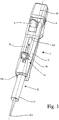
- Fig. 1
- eine perspektivische Darstellung einer erfindungsgemäßen Pipette mit eingesetzter Spritze,
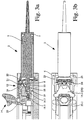
- Fig. 2a
- im Längsschnitt, ausschnittweise am unteren Ende des Pipettengehäuses, ein bevorzugtes Ausführungsbeispiel einer Pipette gemäß der Erfindung mit eingesetzter Spritze, bereit zum Aufsaugen von Flüssigkeit,
- Fig. 2b
- eine Draufsicht der Pipette nach
Fig. 2a , - Fig. 3a
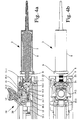
- in einem
Fig. 2a ähnlichen Längsschnitt die Pipette gemäß der Erfindung mit eingesetzter Spritze und geöffneter Kolbengreifeinrichtung, - Fig. 3b
- in einer
Fig. 2b ähnlichen Draufsicht die Pipette nachFig. 3a , - Fig. 4a
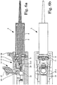
- in einem
Fig. 2a ähnlichen Längsschnitt die Pipette gemäß der Erfindung, mit geöffneter Kolben- und Zylindergreifeinrichtung mit gerade entnommener oder einzusetzender Spritze, - Fig. 4b
- in einer
Fig. 2b ähnlichen Draufsicht die Pipette nachFig. 4a , - Fig. 5a
- im Längsschnitt, ausschnittweise am unteren Ende des Pipettengehäuses, ein weiteres Ausführungsbeispiel einer Pipette gemäß der Erfindung mit eingesetzter Spritze, bereit zum Aufsaugen von Flüssigkeit,
- Fig. 5b
- eine Draufsicht auf die Pipette nach
Fig. 5a , - Fig. 6a
- in einem
Fig. 3a ähnlichen Längsschnitt das weitere Ausführungsbeispiel mit eingesetzter Spritze und geöffneter Kolbengreifeinrichtung, - Fig. 6b
- in einer
Fig. 3b ähnlichen Draufsicht die Pipette nachFig. 6a , - Fig. 7a
- in einem
Fig. 4a ähnlichen Längsschnitt das weitere Ausführungsbeispiel mit geöffneter Kolben- und Zylindergreifeinrichtung mit entnommener oder einzusetzender Spritze, - Fig. 7b
- in einer
Fig. 4b ähnlichen Draufsicht die Pipette nachFig. 7a , - Fig. 8
- Detailansichten eines bevorzugten Ausführungsbeispiels der Betätigungseinrichtung einer Pipette gemäß der Erfindung.
- Fig. 1
- a perspective view of a pipette according to the invention with inserted syringe,
- Fig. 2a
- in a longitudinal section, partially at the lower end of the pipette housing, a preferred embodiment of a pipette according to the invention with inserted syringe, ready for the absorption of liquid,
- Fig. 2b
- a top view of the pipette after
Fig. 2a . - Fig. 3a
- in one
Fig. 2a similar longitudinal section of the pipette according to the invention with inserted syringe and open piston gripping device, - Fig. 3b
- in a
Fig. 2b similar top view the pipette behindFig. 3a . - Fig. 4a
- in one
Fig. 2a similar longitudinal section of the pipette according to the invention, with opened piston and Zylindergreifeinrichtung with just removed or to be used syringe, - Fig. 4b
- in a
Fig. 2b similar top view the pipette behindFig. 4a . - Fig. 5a
- in a longitudinal section, partially at the lower end of the pipette housing, a further embodiment of a pipette according to the invention with inserted syringe, ready for the absorption of liquid,
- Fig. 5b
- a top view of the pipette after
Fig. 5a . - Fig. 6a
- in one
Fig. 3a similar longitudinal section the further embodiment with inserted syringe and open piston gripping device, - Fig. 6b
- in a
Fig. 3b similar top view the pipette behindFig. 6a . - Fig. 7a
- in one
Fig. 4a similar longitudinal section the further embodiment with opened piston and Zylindergreifeinrichtung with removed or inserted syringe, - Fig. 7b
- in a
Fig. 4b similar top view the pipette behindFig. 7a . - Fig. 8
- Detailed views of a preferred embodiment of the actuator of a pipette according to the invention.
Die Spritze 2 besteht typischerweise aus Kunststoffmaterial und weist einen Zylinder 5 mit einem Befestigungsabschnitt 6 und einen in dem Zylinder 5 laufenden Kolben 7 mit einem Kolbenkopf 8 auf. Die Spritze 2 selbst ist für sich handhabbar und auswechselbar, Die jeweils mit der Pipette 1 zu handhabende, auswechselbare Spritze 2 kann bei der in
In den Zylinder 5 der Spritze 2 wird über die unten angedeutete Ansaugöffnung 2.1 Flüssigkeit eingesogen und durch Betätigen der Taste 3 geteilt in mehrere einander folgende Teilmengen wieder abgegeben.Into the
Die folgenden
Aus
Die Pipette 1 weist ein Pipettengehäuse 9 auf, das eine Längsachse 10 aufweist. Die Spritze 2 ist in das Pipettengehäuse 9 an einer dortigen axialen Öffnung 9.1 so eingesetzt, dass sie in Richtung der Längsachse 10 ausgerichtet ist. Im nachfolgenden Text beziehen sich alle Richtungsangaben auf die Längsachse 10. Der Begriff "axial" bedeutet "in Richtung der Längsachse 10", schließt allerdings Linien parallel zur Längsachse 10 selbst ein. In
Aus einer Verbindung von
Ferner ist im Pipettengehäuse 9 axial verschiebbar eine Kolbenstelleinrichtung 12 vorgesehen. Die Kolbenstelleinrichtung 12 wird durch Betätigen der Taste 3 zum Ausstoßen von Teilmengen von Flüssigkeit aus der Spritze 2 angetrieben. An der Kolbenstelleinrichtung 12 ist eine Kolbengreifeinrichtung 13 für den Kolbenkopf 8 der Spritze 2 angebracht, die axial zugänglich und mit der Kolbenstelleinrichtung 12 im Pipettengehäuse 9 axial verschiebbar ist.Further, a
An der Kolbenstelleinrichtung 12 befindet sich eine Betätigungseinrichtung 14 für die Kolbengreifeinrichtung 13. Die Kolbengreifeinrichtung 13 ist durch Betätigen der Betätigungseinrichtung 14 aus einer Greifposition,
Die Kolbenstelleinrichtung 12 wird im dargestellten Ausführungsbeispiel auch zum Verfahren in axialer Richtung, vorwiegend zum Aufsaugen von Flüssigkeit, mittels der Betätigungseinrichtung 14 angetrieben. Man erkennt dazu im Pipettengehäuse 9 eine Öffnung 9.2 für die Betätigungseinrichtung 14 der Kolbenstelleinrichtung 12. Zum Aufsaugen von Flüssigkeit in die Spritze 2 hinein wird die Betätigungseinrichtung 14 in
Wesentlich ist nun, dass die Betätigungseinrichtung 14 für die Kolbengreifeinrichtung 13 an der Kolbenstelleinrichtung 12 angebracht und mit dieser axial verschiebbar ist, wie das
Die zuvor erläuterte grundsätzliche Lehre der Erfindung ist in
Für das in den
In
In
Das dargestellte und bevorzugte Ausführungsbeispiel zeigt dabei, dass hier der Kolbenkopfgreifer 16 einteilig ausgeführt ist, gewissermaßen als U-förmiger Korpus. Grundsätzlich könnte der Kolbenkopfgreifer 16 aber auch aus mehreren Bestandteilen aufgebaut sein.The illustrated and preferred embodiment shows that here the
Ein Vergleich von
Am Druckstück 19 findet sich eine Einführschräge 19.2. Nach bevorzugter Lehre befindet sich am Druckstück 19 auch eine axial ausgerichtete Anschlagfläche 19.3, die den Kolbenkopf 8 einer in das Pipettengehäuse 9 eingeschobenen Spritze 2 axial abstützt und so die zuvor geschilderte Vorschubfunktion erfüllt.At the
Nach bevorzugter Lehre der Erfindung ist auch der Anschlag 18 am Druckstück 19 angeordnet. Das Druckstück 19 vereint also die axiale Vorschubfunktion mit der Niederhalterfunktion für den Kolbenkopf 8.After preferred teaching of the invention, the
Ein Vergleich von
Die gesamte Konstruktion mit dem axial federbelasteten Druckstück 19 gewährleistet, dass der Kolben 7 stets ganz in den Zylinder 5 geschoben ist. Beim Aufsaugen von Flüssigkeit in die Spritze 2 ist so die verbleibende Luftmenge so gering wie möglich.The entire construction with the axially spring-loaded
Die axiale Verschiebebewegung des Druckstücks 19 unter Wirkung der Druckfeder 19.1 kann man zur Steuerung der Kolbengreifeinrichtung 13 nutzen. Nach bevorzugter und hier dargestellter Lehre der Erfindung ist dazu vorgesehen, dass das Druckstück 19 in seiner vorderen Position die Kolbengreifeinrichtung 13 blockiert, so dass der Kolbenkopfgreifer 16 nicht in die Greifposition verstellbar ist, und in der hinteren Position die Kolbengreifeinrichtung 13 freigibt, so dass der Kolbenkopfgreifer 16 in die Greifposition verstellbar ist.The axial displacement movement of the
In der in
Im Ausführungsbeispiel von
Die Betätigungseinrichtung 14 bzw. der Betätigungshebel 17 der Betätigungseinrichtung 14, ist um die sowohl quer zur Längsachse als auch quer zur Verschieberichtung verlaufende Schwenkachse 20 schwenkbar. Man erkennt, dass die Schwenkachse 20 radial verschiebbar oder verstellbar ist. Das sieht man im Vergleich von
Im dargestellten und bevorzugten Ausführungsbeispiel kann man sehen, dass die Klemmbacken 21 mit Profilierungen 22 (
Die Profilierungen 22 sind, in Greifposition betrachtet, so angeordnet, dass sie ungleich zur Mittellinie des Kolbenkopfes 8 der Spritze 2 liegen. Sie sind also etwas schräg, gewissermaßen windschief und ggf. auch versetzt zur Längsachse 10 verlaufend angeordnet. Die Betätigungskraft für den Kolbenkopfgreifer 16 ist so geringer, als wenn die Profilierungen 22 in Greifposition genau in Richtung der Längsachse 10 angeordnet wären.The
Geht man von
Der Kolbenkopfgreifer 16 erzeugt in der Greifposition mit seinem in diesem Ausführungsbeispiel U-förmigen Körper und den seitlich angeordneten Klemmbacken 21 die Klemmkraft am Kolbenkopf 8 ohne aus dem Stand der Technik genannte Gelenkgetriebe oder Federunterstützung. Im dargestellten und bevorzugten Ausführungsbeispiel ist der Kolbenkopfgreifer 16 einteilig ausgeführt. Grundsätzlich wäre es auch möglich, den Kolbenkopfgreifer 16 in mehreren Teilen aufzubauen.The
Die Profilierungen 22 an den Klemmbacken 21 können unmittelbar am Material des Kolbenkopfgreifers 16 ausgeformt sein. Eine Alternative besteht in separaten Schneidenrollen als Profilierungen 22. Solche Schneidenrollen können aus relativ hartem Werkstoff, beispielsweise Stahl oder hartem Kunststoff bestehen und sind dann in die Klemmbacken 21 eingesetzt.The
Eine eigenständige Stabilisierung der Konstruktion in Greifposition ergibt sich dadurch, dass die Profilierungen 22 bei in der Greifposition befindlichem Kolbenkopfgreifer 16 unterhalb einer Mittellinie des Kolbenkopfes 8 der Spritze 2 liegen.An independent stabilization of the construction in gripping position results from the fact that the
Zuvor ist bereits darauf hingewiesen worden, dass das Druckstück 19 eine Einführschräge 19.2 aufweist, um das axiale Einschieben des Kolbenkopfes 8 der Spritze 2 zu erleichtern. Eine entsprechende Einführschräge 12.1 kann auch an der Auflage 15, die an der Kolbenstelleinrichtung 12 ausgebildet ist, vorgesehen sein. Das ist in
Aus den Draufsichten in
In
Im Übergang von
Für die Bewegungsabfolge der Betätigungseinrichtung 14 bzw. ihres Betätigungshebels 17 wird auf
In
Die in
Anhand von
Die Steuerung des Kolbenkopfgreifers 16 erfolgt durch den Betätigungshebel 17 der Betätigungseinrichtung 14. Hier ist der Ablauf so wie beim ersten Ausführungsbeispiel, wenn man den Übergang von
Im Übergang von
Nicht dargestellt ist in der Zeichnung eine Variante, bei der die beiden Betätigungsmöglichkeiten für die Zylindergreifeinrichtung 11 der beiden Ausfühnmgsbeispiele von
Claims (15)
- Pipette- for a pipette system, which consists of a pipette (1) and a syringe (2), where the syringe (2) has a cylinder (5) with a fastening portion (6) realized preferably as a flange and a plunger (7) with a plunger head (8) which projects out of the end of the cylinder (5) even when the plunger (7) has been completely inserted into the cylinder (5),
having a pipette housing (9) which has a longitudinal axis (10),- wherein a syringe (2) to be handled with the pipette (1) is insertable with its fastening portion (6) and plunger head (8) into the pipette housing (9) and is removable or discardable from said pipette housing in the direction of the longitudinal axis (10) of the pipette housing (9), i.e. axially,
having an axially accessible opening (9.1) on the pipette housing (9) for the fastening portion (6) of the syringe (2),
having an axially accessible cylinder gripping device (11), mounted fixed in position in the pipette housing (9), for the fastening portion (6) of a syringe (2), having a plunger adjusting device (12) which is axially displaceable in the pipette housing (9),
having an axially accessible plunger gripping device (13) for the plunger head (8) of a syringe (2), said plunger gripping device being mounted on the plunger adjusting device (12) and being axially displaceable with said plunger adjusting device and
having an actuating device (14) for the plunger gripping device (13), wherein, by actuating the actuating device (14), the plunger gripping device (13) is movable from a grip position into a release position, in which the plunger head (8) of a syringe (2) is released for removal or picking up, characterized in that,
the actuating device (14) for the plunger gripping device (13) is mounted on the plunger adjusting device (12) and is axially displaceable with said plunger adjusting device. - Pipette according to Claim 1, characterized in that the plunger gripping device (13) is also movable out of the release position into the grip position by actuating the actuating device (14), in that the plunger gripping device (13) has a support (15), which radially supports the plunger head (8) of a syringe (2) inserted into the pipette housing (9) transversely in relation to the longitudinal axis (10) of the pipette housing (9), and an adjustable plunger head gripping means (16), in that, by actuating the actuating device (14), the plunger head gripping means (16) is adjustable from the release position, releasing the plunger head (8), into the grip position, fixing the plunger head (8) on the plunger adjusting device (12), and in that, by means of the actuating device (14), the plunger head gripping means (16) is adjustable in relation to the support (15) in an adjustment movement which has at least one considerable radial component, wherein the plunger head gripping means (16) is for this purpose, preferably, pivotably mounted on the plunger adjusting device (12).
- Pipette according to Claim 2, characterized in that the plunger adjusting device (12) has a stop member (18), which supports the plunger head (8) of a syringe (2) inserted into the pipette housing (9) in a direction that differs from the supporting direction of the support (15), preferably radially, in opposition to the adjustment movement of the plunger head gripping means (16) into the release position.
- Pipette according to one of Claims 1 to 3, characterized in that the plunger adjusting device (12) has an axially deflecting pressure piece (19), on which is arranged firstly the stop member (18) and secondly an axially aligned stopping face (19.3), which supports in an axial manner the plunger head (8) of a syringe (2) inserted into the pipette housing (9), wherein, preferably, the pressure piece (19) is axially pretensioned against the plunger head (8) of the syringe (2) to be axially inserted and thus assumes a front position without a syringe (2) and a rear position with an inserted syringe (2), and, in its front position, the pressure piece (19) blocks the plunger gripping device (13) such that the plunger head gripping means (16) is not adjustable into the grip position, and, in its rear position, said pressure piece releases the plunger gripping device (13) such that the plunger head gripping means (16) is adjustable into the grip position.
- Pipette according to Claim 2 and, where applicable, Claim 3 or 4, characterized in that the actuating device (14) is mounted in such a manner on the plunger adjusting device (12) that it is radially adjustable for adjusting the plunger head gripping means (16) from the grip position into the release position and, as an additional option, is pivotable about a pivot axis (20) that extends both transversely in relation to the longitudinal axis (10) and transversely in relation to the direction of displacement.
- Pipette according to Claim 2 and, where applicable, one of Claims 3 to 5, characterized in that, in the grip position, the plunger head gripping means (16) grips the plunger head (8) of an inserted syringe (2) with preferably laterally arranged clamping jaws (21) and holds it preferably in a laterally clamping manner, transmitting considerable tensile forces axially from the plunger adjusting device (12) to the plunger (7), wherein, preferably, the clamping jaws (21) are provided with profilings (22), in particular with cutting edge-like profilings and/or with cutting rollers, wherein, more preferably, with the plunger head gripping means (16) in the grip position, the profilings (22) or the cutting rollers lie unequally in relation to the centre line of the plunger head (8) of the syringe (2).
- Pipette according to Claim 2 and, where applicable, one of Claims 3 to 6, characterized in that the support (15), and preferably also the stop member (18), has feed-in inclinations (12.1; 19.2) in order to facilitate the axial insertion of the plunger head (8) of the syringe (2).
- Pipette according to one of Claims 1 to 7, characterized in that the cylinder gripping device (11) has at least two cylinder gripping levers (23), which are mounted so as to be pivotable in the pipette housing (9) and are set radially under spring force towards the fastening portion (6) of an inserted syringe (2), and in that, preferably, each cylinder gripping lever (23) has a driving arm (24).
- Pipette according to one of Claims 1 to 8, characterized in that the cylinder gripping device (11) is also adjustable between a grip position and a release position by means of the actuating device (14), wherein, preferably, for adjusting the plunger head gripping means (16) from the grip position into the release position, the actuating device (14) carries out a pivoting movement forward, i.e. in the direction of the syringe (2), and for adjusting the cylinder gripping device (11) from the grip position into the release position said pivoting movement is continued forward.
- Pipette according to Claims 8 and 9, characterized in that as the pivoting movement of the actuating device (14) is continued, the cylinder gripping levers (23) of the cylinder gripping device (11) are adjusted away from the fastening portion (6) of an inserted syringe (2).
- Pipette according to Claim 9 or 10, characterized in that the actuating device (14) has associated therewith a spring element (14.1), which acts in the direction of the pivoting movement for adjusting the plunger head gripping means (16) from the grip position into the release position, wherein, preferably, as the pivoting movement continues for adjusting the cylinder gripping device (11), the spring element (14.1) is made ineffective.
- Pipette according to Claim 10 and, where applicable, Claim 11, characterized in that the actuating device (14), as its pivoting movement continues, drives a force transmitting train (14.2), which, by means of the driving arms (24), opens the cylinder gripping levers (23) of the cylinder gripping device (11) in a symmetrical manner.
- Pipette according to Claim 12, characterized in that the pipette (1) has a cover (25) for closing an opening (9.2) in the pipette housing (9) for the actuating device (14) of the plunger adjusting device (12) and in that the cover (25) forms the force transmitting train (14.2).
- Pipette according to Claim 8, characterized in that an additional actuating slide (26) for actuating the cylinder gripping device (11) is arranged on the pipette housing (9).
- Pipette according to Claim 14, characterized in that the actuating slide (26) opens the cylinder gripping levers (23) of the cylinder gripping device (11) in a symmetrical manner by means of the driving arms (24).
Applications Claiming Priority (1)
| Application Number | Priority Date | Filing Date | Title |
|---|---|---|---|
| DE202010009747U DE202010009747U1 (en) | 2010-07-01 | 2010-07-01 | Pipette for a pipette system with pipette and syringe |
Publications (3)
| Publication Number | Publication Date |
|---|---|
| EP2428271A2 EP2428271A2 (en) | 2012-03-14 |
| EP2428271A3 EP2428271A3 (en) | 2014-03-19 |
| EP2428271B1 true EP2428271B1 (en) | 2017-06-21 |
Family
ID=43123289
Family Applications (1)
| Application Number | Title | Priority Date | Filing Date |
|---|---|---|---|
| EP11005349.3A Active EP2428271B1 (en) | 2010-07-01 | 2011-06-30 | Pipette for a pipette system with pipette and syringe |
Country Status (3)
| Country | Link |
|---|---|
| US (1) | US8652418B2 (en) |
| EP (1) | EP2428271B1 (en) |
| DE (1) | DE202010009747U1 (en) |
Families Citing this family (15)
| Publication number | Priority date | Publication date | Assignee | Title |
|---|---|---|---|---|
| DE102007010299B4 (en) * | 2007-03-02 | 2009-01-29 | Eppendorf Ag | Handpipettiervorrichtung |
| WO2009060485A1 (en) * | 2007-11-08 | 2009-05-14 | Aea S.R.L. | Assembly for actuating a syringe |
| WO2010051824A1 (en) | 2008-11-05 | 2010-05-14 | Hamilton Bonaduz Ag | Radial sliding seal component for metering devices and metering device having such a radial sliding seal component |
| DE202010010942U1 (en) | 2010-08-03 | 2011-11-08 | Brand Gmbh + Co Kg | Pipette for a pipette system with pipette and syringe |
| US8632738B2 (en) * | 2010-08-30 | 2014-01-21 | Health Robotics S.r.l | Syringe actuating method and assembly |
| PL2656915T3 (en) * | 2012-04-23 | 2019-04-30 | Eppendorf Ag | Pipette for actuating an injection |
| US9751082B1 (en) | 2014-05-22 | 2017-09-05 | Dunsong Yang | Multi-actuated micro-pipette controller and associated use thereof |
| CN104001563B (en) * | 2014-06-09 | 2015-07-08 | 上海优爱宝机器人技术有限公司 | Pipettor |
| DE102016121810A1 (en) * | 2016-11-14 | 2018-05-17 | Ika-Werke Gmbh & Co. Kg | manual proportioning device |
| DE202017101009U1 (en) * | 2017-02-23 | 2018-05-24 | Brand Gmbh + Co Kg | Attaching and detaching a piston-cylinder unit to or from a dispenser for receiving and dispensing fluid volumes |
| US11369954B2 (en) | 2019-10-25 | 2022-06-28 | Mettler-Toledo Rainin, LLC | Powered positive displacement pipette assembly |
| US11446672B2 (en) | 2019-10-25 | 2022-09-20 | Mettler-Toledo Rainin, LLC | Powered positive displacement pipette syringe piston grasping mechanism |
| US11911767B2 (en) | 2019-10-25 | 2024-02-27 | Mettler-Toledo Rainin, LLC | Positive displacement pipette syringe identification system |
| US11389792B2 (en) | 2019-10-25 | 2022-07-19 | Mettler-Toledo Rainin, LLC | Syringe for powered positive displacement pipette |
| US11471878B2 (en) | 2019-10-25 | 2022-10-18 | Mettler-Toledo Rainin, LLC | Powered positive displacement pipette |
Family Cites Families (11)
| Publication number | Priority date | Publication date | Assignee | Title |
|---|---|---|---|---|
| DE2926691C2 (en) | 1979-07-02 | 1983-05-26 | Eppendorf Gerätebau Netheler + Hinz GmbH, 2000 Hamburg | Repeater pipette |
| US4099548A (en) * | 1976-08-25 | 1978-07-11 | Oxford Laboratories Inc. | Hand-held pipette for repetitively dispensing precise volumes of liquid |
| DE4341229C2 (en) | 1993-12-03 | 1995-09-07 | Eppendorf Geraetebau Netheler | Pipette system |
| DE4342178C2 (en) * | 1993-12-10 | 1995-09-28 | Eppendorf Geraetebau Netheler | Pipette system |
| DE4414744C1 (en) * | 1994-04-27 | 1995-11-02 | Eppendorf Geraetebau Netheler | Repeater pipette |
| DE19917907C2 (en) | 1999-04-20 | 2001-08-16 | Brand Gmbh & Co Kg | Pipette for a pipette system |
| DE19963141A1 (en) | 1999-12-24 | 2001-07-12 | Brand Gmbh & Co Kg | Pipette for a pipetting system |
| FI116613B (en) | 2003-10-17 | 2006-01-13 | Biohit Oyj | A method for attaching a pipette tip and a device for performing the method |
| DE102005023203B4 (en) | 2005-05-20 | 2009-06-04 | Eppendorf Ag | pipette |
| DE102007010299B4 (en) * | 2007-03-02 | 2009-01-29 | Eppendorf Ag | Handpipettiervorrichtung |
| DE102007042115B4 (en) * | 2007-09-05 | 2010-12-02 | Eppendorf Ag | pipette |
-
2010
- 2010-07-01 DE DE202010009747U patent/DE202010009747U1/en not_active Expired - Lifetime
-
2011
- 2011-06-30 EP EP11005349.3A patent/EP2428271B1/en active Active
- 2011-07-01 US US13/174,854 patent/US8652418B2/en active Active
Non-Patent Citations (1)
| Title |
|---|
| None * |
Also Published As
| Publication number | Publication date |
|---|---|
| EP2428271A3 (en) | 2014-03-19 |
| US20120003129A1 (en) | 2012-01-05 |
| DE202010009747U1 (en) | 2010-11-18 |
| US8652418B2 (en) | 2014-02-18 |
| EP2428271A2 (en) | 2012-03-14 |
Similar Documents
| Publication | Publication Date | Title |
|---|---|---|
| EP2428271B1 (en) | Pipette for a pipette system with pipette and syringe | |
| EP2578171B1 (en) | Surgical instrument | |
| EP1699508B1 (en) | Insertion unit for puncture devices | |
| EP2713819B1 (en) | Fastening device for mounting a front cover on a drawer | |
| EP2033712B1 (en) | Pipette | |
| EP1631337B1 (en) | Insertion device for infusion sets | |
| EP2713821B1 (en) | Fastening device for fastening a front panel on a drawer | |
| DE2166983A1 (en) | SURGICAL INSTRUMENT FOR PUTTING CLAMPS TO TIE TUBE-SHAPED ORGANIC FORMATS | |
| EP2574379A2 (en) | Front device | |
| EP1110612A2 (en) | Pipetting system with pipette and syringe tip | |
| WO2016197162A1 (en) | Ejection device for a movable furniture part | |
| DE3690236C2 (en) | Blind riveter accessory for drilling machine | |
| EP0399322A3 (en) | Stitching device | |
| EP0940203A2 (en) | Hand riveting tool for blind rivets | |
| EP2732877B1 (en) | Piston stroke pipette with exchangeable displacer unit | |
| EP2402092B1 (en) | Extruder | |
| EP2322745A1 (en) | Device for opening a movable furniture part | |
| DE3141248C2 (en) | Device for feeding screws for a motorized screwdriver | |
| WO2008154964A1 (en) | Demolding device for demolding a tool from a mold | |
| DE202004017974U1 (en) | Surgical punch | |
| EP1502684B1 (en) | Hand-held machine tool for machining workpieces, particularly in form of a shear for slitting blanks | |
| DE202007017726U1 (en) | Demolding device for demolding a workpiece from a mold | |
| EP2559355A1 (en) | Device for moving a mobile item of furniture, guidance unit and furniture | |
| CH705586A2 (en) | Front machine for ski binding e.g. touring, has levers that are mounted by positive control in retaining position, so that levers are coupled within dynamic range and can be moved in transverse direction | |
| DE102010020655A1 (en) | Water pumping pliers comprise two pliers units that cross in connecting area, where pliers units are swiveled by joint, and spring element is arranged at resting block |
Legal Events
| Date | Code | Title | Description |
|---|---|---|---|
| AK | Designated contracting states |
Kind code of ref document: A2 Designated state(s): AL AT BE BG CH CY CZ DE DK EE ES FI FR GB GR HR HU IE IS IT LI LT LU LV MC MK MT NL NO PL PT RO RS SE SI SK SM TR |
|
| AX | Request for extension of the european patent |
Extension state: BA ME |
|
| PUAI | Public reference made under article 153(3) epc to a published international application that has entered the european phase |
Free format text: ORIGINAL CODE: 0009012 |
|
| PUAL | Search report despatched |
Free format text: ORIGINAL CODE: 0009013 |
|
| AK | Designated contracting states |
Kind code of ref document: A3 Designated state(s): AL AT BE BG CH CY CZ DE DK EE ES FI FR GB GR HR HU IE IS IT LI LT LU LV MC MK MT NL NO PL PT RO RS SE SI SK SM TR |
|
| AX | Request for extension of the european patent |
Extension state: BA ME |
|
| RIC1 | Information provided on ipc code assigned before grant |
Ipc: B01L 3/02 20060101AFI20140207BHEP Ipc: G01F 1/84 20060101ALI20140207BHEP |
|
| 17P | Request for examination filed |
Effective date: 20140321 |
|
| RBV | Designated contracting states (corrected) |
Designated state(s): AL AT BE BG CH CY CZ DE DK EE ES FI FR GB GR HR HU IE IS IT LI LT LU LV MC MK MT NL NO PL PT RO RS SE SI SK SM TR |
|
| GRAP | Despatch of communication of intention to grant a patent |
Free format text: ORIGINAL CODE: EPIDOSNIGR1 |
|
| STAA | Information on the status of an ep patent application or granted ep patent |
Free format text: STATUS: GRANT OF PATENT IS INTENDED |
|
| INTG | Intention to grant announced |
Effective date: 20170208 |
|
| GRAS | Grant fee paid |
Free format text: ORIGINAL CODE: EPIDOSNIGR3 |
|
| GRAA | (expected) grant |
Free format text: ORIGINAL CODE: 0009210 |
|
| STAA | Information on the status of an ep patent application or granted ep patent |
Free format text: STATUS: THE PATENT HAS BEEN GRANTED |
|
| AK | Designated contracting states |
Kind code of ref document: B1 Designated state(s): AL AT BE BG CH CY CZ DE DK EE ES FI FR GB GR HR HU IE IS IT LI LT LU LV MC MK MT NL NO PL PT RO RS SE SI SK SM TR |
|
| REG | Reference to a national code |
Ref country code: GB Ref legal event code: FG4D Free format text: NOT ENGLISH |
|
| REG | Reference to a national code |
Ref country code: CH Ref legal event code: EP Ref country code: FR Ref legal event code: PLFP Year of fee payment: 7 |
|
| REG | Reference to a national code |
Ref country code: IE Ref legal event code: FG4D Free format text: LANGUAGE OF EP DOCUMENT: GERMAN |
|
| REG | Reference to a national code |
Ref country code: AT Ref legal event code: REF Ref document number: 902440 Country of ref document: AT Kind code of ref document: T Effective date: 20170715 |
|
| REG | Reference to a national code |
Ref country code: DE Ref legal event code: R096 Ref document number: 502011012462 Country of ref document: DE |
|
| REG | Reference to a national code |
Ref country code: NL Ref legal event code: MP Effective date: 20170621 |
|
| PG25 | Lapsed in a contracting state [announced via postgrant information from national office to epo] |
Ref country code: LT Free format text: LAPSE BECAUSE OF FAILURE TO SUBMIT A TRANSLATION OF THE DESCRIPTION OR TO PAY THE FEE WITHIN THE PRESCRIBED TIME-LIMIT Effective date: 20170621 Ref country code: HR Free format text: LAPSE BECAUSE OF FAILURE TO SUBMIT A TRANSLATION OF THE DESCRIPTION OR TO PAY THE FEE WITHIN THE PRESCRIBED TIME-LIMIT Effective date: 20170621 Ref country code: NO Free format text: LAPSE BECAUSE OF FAILURE TO SUBMIT A TRANSLATION OF THE DESCRIPTION OR TO PAY THE FEE WITHIN THE PRESCRIBED TIME-LIMIT Effective date: 20170921 Ref country code: GR Free format text: LAPSE BECAUSE OF FAILURE TO SUBMIT A TRANSLATION OF THE DESCRIPTION OR TO PAY THE FEE WITHIN THE PRESCRIBED TIME-LIMIT Effective date: 20170922 Ref country code: FI Free format text: LAPSE BECAUSE OF FAILURE TO SUBMIT A TRANSLATION OF THE DESCRIPTION OR TO PAY THE FEE WITHIN THE PRESCRIBED TIME-LIMIT Effective date: 20170621 |
|
| REG | Reference to a national code |
Ref country code: LT Ref legal event code: MG4D |
|
| PG25 | Lapsed in a contracting state [announced via postgrant information from national office to epo] |
Ref country code: LV Free format text: LAPSE BECAUSE OF FAILURE TO SUBMIT A TRANSLATION OF THE DESCRIPTION OR TO PAY THE FEE WITHIN THE PRESCRIBED TIME-LIMIT Effective date: 20170621 Ref country code: NL Free format text: LAPSE BECAUSE OF FAILURE TO SUBMIT A TRANSLATION OF THE DESCRIPTION OR TO PAY THE FEE WITHIN THE PRESCRIBED TIME-LIMIT Effective date: 20170621 Ref country code: RS Free format text: LAPSE BECAUSE OF FAILURE TO SUBMIT A TRANSLATION OF THE DESCRIPTION OR TO PAY THE FEE WITHIN THE PRESCRIBED TIME-LIMIT Effective date: 20170621 Ref country code: SE Free format text: LAPSE BECAUSE OF FAILURE TO SUBMIT A TRANSLATION OF THE DESCRIPTION OR TO PAY THE FEE WITHIN THE PRESCRIBED TIME-LIMIT Effective date: 20170621 Ref country code: BG Free format text: LAPSE BECAUSE OF FAILURE TO SUBMIT A TRANSLATION OF THE DESCRIPTION OR TO PAY THE FEE WITHIN THE PRESCRIBED TIME-LIMIT Effective date: 20170921 |
|
| PG25 | Lapsed in a contracting state [announced via postgrant information from national office to epo] |
Ref country code: SK Free format text: LAPSE BECAUSE OF FAILURE TO SUBMIT A TRANSLATION OF THE DESCRIPTION OR TO PAY THE FEE WITHIN THE PRESCRIBED TIME-LIMIT Effective date: 20170621 Ref country code: EE Free format text: LAPSE BECAUSE OF FAILURE TO SUBMIT A TRANSLATION OF THE DESCRIPTION OR TO PAY THE FEE WITHIN THE PRESCRIBED TIME-LIMIT Effective date: 20170621 Ref country code: CZ Free format text: LAPSE BECAUSE OF FAILURE TO SUBMIT A TRANSLATION OF THE DESCRIPTION OR TO PAY THE FEE WITHIN THE PRESCRIBED TIME-LIMIT Effective date: 20170621 Ref country code: RO Free format text: LAPSE BECAUSE OF FAILURE TO SUBMIT A TRANSLATION OF THE DESCRIPTION OR TO PAY THE FEE WITHIN THE PRESCRIBED TIME-LIMIT Effective date: 20170621 |
|
| PG25 | Lapsed in a contracting state [announced via postgrant information from national office to epo] |
Ref country code: SM Free format text: LAPSE BECAUSE OF FAILURE TO SUBMIT A TRANSLATION OF THE DESCRIPTION OR TO PAY THE FEE WITHIN THE PRESCRIBED TIME-LIMIT Effective date: 20170621 Ref country code: IS Free format text: LAPSE BECAUSE OF FAILURE TO SUBMIT A TRANSLATION OF THE DESCRIPTION OR TO PAY THE FEE WITHIN THE PRESCRIBED TIME-LIMIT Effective date: 20171021 Ref country code: PL Free format text: LAPSE BECAUSE OF FAILURE TO SUBMIT A TRANSLATION OF THE DESCRIPTION OR TO PAY THE FEE WITHIN THE PRESCRIBED TIME-LIMIT Effective date: 20170621 Ref country code: ES Free format text: LAPSE BECAUSE OF FAILURE TO SUBMIT A TRANSLATION OF THE DESCRIPTION OR TO PAY THE FEE WITHIN THE PRESCRIBED TIME-LIMIT Effective date: 20170621 Ref country code: IT Free format text: LAPSE BECAUSE OF FAILURE TO SUBMIT A TRANSLATION OF THE DESCRIPTION OR TO PAY THE FEE WITHIN THE PRESCRIBED TIME-LIMIT Effective date: 20170621 |
|
| REG | Reference to a national code |
Ref country code: DE Ref legal event code: R097 Ref document number: 502011012462 Country of ref document: DE |
|
| PG25 | Lapsed in a contracting state [announced via postgrant information from national office to epo] |
Ref country code: MC Free format text: LAPSE BECAUSE OF FAILURE TO SUBMIT A TRANSLATION OF THE DESCRIPTION OR TO PAY THE FEE WITHIN THE PRESCRIBED TIME-LIMIT Effective date: 20170621 |
|
| REG | Reference to a national code |
Ref country code: IE Ref legal event code: MM4A |
|
| PLBE | No opposition filed within time limit |
Free format text: ORIGINAL CODE: 0009261 |
|
| STAA | Information on the status of an ep patent application or granted ep patent |
Free format text: STATUS: NO OPPOSITION FILED WITHIN TIME LIMIT |
|
| PG25 | Lapsed in a contracting state [announced via postgrant information from national office to epo] |
Ref country code: LU Free format text: LAPSE BECAUSE OF NON-PAYMENT OF DUE FEES Effective date: 20170630 Ref country code: IE Free format text: LAPSE BECAUSE OF NON-PAYMENT OF DUE FEES Effective date: 20170630 Ref country code: DK Free format text: LAPSE BECAUSE OF FAILURE TO SUBMIT A TRANSLATION OF THE DESCRIPTION OR TO PAY THE FEE WITHIN THE PRESCRIBED TIME-LIMIT Effective date: 20170621 |
|
| GBPC | Gb: european patent ceased through non-payment of renewal fee |
Effective date: 20170921 |
|
| 26N | No opposition filed |
Effective date: 20180322 |
|
| REG | Reference to a national code |
Ref country code: BE Ref legal event code: MM Effective date: 20170630 |
|
| REG | Reference to a national code |
Ref country code: FR Ref legal event code: PLFP Year of fee payment: 8 |
|
| PG25 | Lapsed in a contracting state [announced via postgrant information from national office to epo] |
Ref country code: GB Free format text: LAPSE BECAUSE OF NON-PAYMENT OF DUE FEES Effective date: 20170921 |
|
| REG | Reference to a national code |
Ref country code: AT Ref legal event code: MM01 Ref document number: 902440 Country of ref document: AT Kind code of ref document: T Effective date: 20170630 |
|
| PG25 | Lapsed in a contracting state [announced via postgrant information from national office to epo] |
Ref country code: SI Free format text: LAPSE BECAUSE OF FAILURE TO SUBMIT A TRANSLATION OF THE DESCRIPTION OR TO PAY THE FEE WITHIN THE PRESCRIBED TIME-LIMIT Effective date: 20170621 Ref country code: BE Free format text: LAPSE BECAUSE OF NON-PAYMENT OF DUE FEES Effective date: 20170630 |
|
| PG25 | Lapsed in a contracting state [announced via postgrant information from national office to epo] |
Ref country code: MT Free format text: LAPSE BECAUSE OF FAILURE TO SUBMIT A TRANSLATION OF THE DESCRIPTION OR TO PAY THE FEE WITHIN THE PRESCRIBED TIME-LIMIT Effective date: 20170621 |
|
| PG25 | Lapsed in a contracting state [announced via postgrant information from national office to epo] |
Ref country code: AT Free format text: LAPSE BECAUSE OF NON-PAYMENT OF DUE FEES Effective date: 20170630 |
|
| PG25 | Lapsed in a contracting state [announced via postgrant information from national office to epo] |
Ref country code: HU Free format text: LAPSE BECAUSE OF FAILURE TO SUBMIT A TRANSLATION OF THE DESCRIPTION OR TO PAY THE FEE WITHIN THE PRESCRIBED TIME-LIMIT; INVALID AB INITIO Effective date: 20110630 |
|
| PG25 | Lapsed in a contracting state [announced via postgrant information from national office to epo] |
Ref country code: CY Free format text: LAPSE BECAUSE OF NON-PAYMENT OF DUE FEES Effective date: 20170621 |
|
| PG25 | Lapsed in a contracting state [announced via postgrant information from national office to epo] |
Ref country code: MK Free format text: LAPSE BECAUSE OF FAILURE TO SUBMIT A TRANSLATION OF THE DESCRIPTION OR TO PAY THE FEE WITHIN THE PRESCRIBED TIME-LIMIT Effective date: 20170621 |
|
| PG25 | Lapsed in a contracting state [announced via postgrant information from national office to epo] |
Ref country code: TR Free format text: LAPSE BECAUSE OF FAILURE TO SUBMIT A TRANSLATION OF THE DESCRIPTION OR TO PAY THE FEE WITHIN THE PRESCRIBED TIME-LIMIT Effective date: 20170621 |
|
| PG25 | Lapsed in a contracting state [announced via postgrant information from national office to epo] |
Ref country code: PT Free format text: LAPSE BECAUSE OF FAILURE TO SUBMIT A TRANSLATION OF THE DESCRIPTION OR TO PAY THE FEE WITHIN THE PRESCRIBED TIME-LIMIT Effective date: 20170621 |
|
| PG25 | Lapsed in a contracting state [announced via postgrant information from national office to epo] |
Ref country code: AL Free format text: LAPSE BECAUSE OF FAILURE TO SUBMIT A TRANSLATION OF THE DESCRIPTION OR TO PAY THE FEE WITHIN THE PRESCRIBED TIME-LIMIT Effective date: 20170621 |
|
| PGFP | Annual fee paid to national office [announced via postgrant information from national office to epo] |
Ref country code: FR Payment date: 20230627 Year of fee payment: 13 Ref country code: DE Payment date: 20230619 Year of fee payment: 13 |
|
| PGFP | Annual fee paid to national office [announced via postgrant information from national office to epo] |
Ref country code: CH Payment date: 20230702 Year of fee payment: 13 |