EP2428012B1 - Verringerung des Verhältnisses von Spitzen-zu-Durchschnittsleistung in einem Mehrträgersignal - Google Patents
Verringerung des Verhältnisses von Spitzen-zu-Durchschnittsleistung in einem Mehrträgersignal Download PDFInfo
- Publication number
- EP2428012B1 EP2428012B1 EP10722977.5A EP10722977A EP2428012B1 EP 2428012 B1 EP2428012 B1 EP 2428012B1 EP 10722977 A EP10722977 A EP 10722977A EP 2428012 B1 EP2428012 B1 EP 2428012B1
- Authority
- EP
- European Patent Office
- Prior art keywords
- sub
- carriers
- transition
- channel estimation
- pilot
- Prior art date
- Legal status (The legal status is an assumption and is not a legal conclusion. Google has not performed a legal analysis and makes no representation as to the accuracy of the status listed.)
- Not-in-force
Links
- 230000009467 reduction Effects 0.000 title description 23
- 230000007704 transition Effects 0.000 claims description 157
- 238000012937 correction Methods 0.000 claims description 148
- 239000000969 carrier Substances 0.000 claims description 98
- 238000000034 method Methods 0.000 claims description 77
- 230000005540 biological transmission Effects 0.000 claims description 72
- 239000000654 additive Substances 0.000 claims description 35
- 230000000996 additive effect Effects 0.000 claims description 35
- 238000012986 modification Methods 0.000 claims description 19
- 230000004048 modification Effects 0.000 claims description 19
- 238000012545 processing Methods 0.000 claims description 13
- 238000004458 analytical method Methods 0.000 claims description 9
- 238000004590 computer program Methods 0.000 claims description 6
- 238000004891 communication Methods 0.000 claims description 5
- 230000008054 signal transmission Effects 0.000 claims description 5
- 230000011664 signaling Effects 0.000 claims description 5
- 230000002123 temporal effect Effects 0.000 claims description 5
- 238000012935 Averaging Methods 0.000 claims description 4
- 238000005457 optimization Methods 0.000 description 17
- 238000004422 calculation algorithm Methods 0.000 description 9
- 238000000605 extraction Methods 0.000 description 7
- 230000003595 spectral effect Effects 0.000 description 6
- 238000013459 approach Methods 0.000 description 5
- 241001080024 Telles Species 0.000 description 4
- 230000003321 amplification Effects 0.000 description 4
- 238000004364 calculation method Methods 0.000 description 4
- 238000003199 nucleic acid amplification method Methods 0.000 description 4
- 238000004088 simulation Methods 0.000 description 3
- 241001644893 Entandrophragma utile Species 0.000 description 2
- 230000006872 improvement Effects 0.000 description 2
- 238000003780 insertion Methods 0.000 description 2
- 230000037431 insertion Effects 0.000 description 2
- 230000004044 response Effects 0.000 description 2
- 238000011282 treatment Methods 0.000 description 2
- 240000008042 Zea mays Species 0.000 description 1
- 238000012550 audit Methods 0.000 description 1
- 230000015556 catabolic process Effects 0.000 description 1
- 238000006731 degradation reaction Methods 0.000 description 1
- 238000001514 detection method Methods 0.000 description 1
- 238000011156 evaluation Methods 0.000 description 1
- 238000013507 mapping Methods 0.000 description 1
- 239000011159 matrix material Substances 0.000 description 1
- 230000008569 process Effects 0.000 description 1
- 239000007787 solid Substances 0.000 description 1
- 238000001228 spectrum Methods 0.000 description 1
Images


Classifications
-
- H—ELECTRICITY
- H04—ELECTRIC COMMUNICATION TECHNIQUE
- H04L—TRANSMISSION OF DIGITAL INFORMATION, e.g. TELEGRAPHIC COMMUNICATION
- H04L27/00—Modulated-carrier systems
- H04L27/26—Systems using multi-frequency codes
- H04L27/2601—Multicarrier modulation systems
- H04L27/2614—Peak power aspects
- H04L27/2618—Reduction thereof using auxiliary subcarriers
Definitions
- the field of the invention is that of the transmission of digital signals, either on multipath transmission channels, or on so-called “single-path” channels, such as those of satellite links without echo in particular.
- the invention relates to multicarrier modulation techniques, particularly OFDM type (" Orthogonal Frequency Division Multiplex" in English for “orthogonal frequency division multiplexing”).
- OFDM modulation is increasingly used for digital transmission, especially on multipath transmission channels.
- This multicarrier modulation technique notably makes it possible to overcome the inter-symbol interference generally observed when using a single-carrier modulation on a multipath channel.
- OFDM modulation is notably, but not exclusively, used in wireless local area networks (WiFI or WiMAX) or ADSL (" Asymmetric Digital Subscriber").
- Line and the HIPERLAN / 2 (" Hlgh PErformance Radio Local Area Network "), but also for standards such as those relating to the broadcast Digital Audio (DAB for " Digital Audio Broadcasting "in English), Digital Video Broadcasting (DVB), in particular DVB-T (a digital terrestrial television standard) or the new DVB-T2 standard or DVB-NGH (“DVB - Next Generation”) Handheld “, a video broadcast standard for mobile terminal reception).
- DAB Digital Audio Broadcasting
- DVD Digital Video Broadcasting
- DVB-T digital terrestrial television standard
- DVB-NGH DVB-NGH
- a major disadvantage of the OFDM technique is inherent to the large amplitude fluctuations of the envelope of the modulated signal and therefore to the large variations in the instantaneous power.
- the report peak power to average power (PAPR for "Peak to Average Power Ratio” in English) of the transmitted signals is generally very high and it increases with the number of subcarriers N.
- the power amplifiers have non-linear characteristics which, coupled with the amplification of so-called high-frequency signals, lead to distortions: spectral rise in the level of the secondary lobes, generation of harmonics, creation of interferences between non-linear symbols, creation of interferences between carriers.
- these distortions lead in particular to transmission errors and a degradation of the bit error rate (BER).
- a common solution is to ensure that the operating range of the amplifier remains limited to a linear amplification zone, which unfortunately limits the efficiency of the amplifier (a few% instead of, typically, 50%) and therefore a significant increase in the consumption of the transmitter. This is a very strong constraint for the use of OFDM especially in mobile terminals, knowing that the consumption of the power amplifier can represent more than 50% of the total consumption of a terminal.
- a second approach is the " clippitig” technique, which consists of clipping the amplitude of the signal when it exceeds a predefined threshold. But this clipping is by nature non-linear and introduces a distortion of the emitted signal resulting not only in a degraded BER but also in a rise in the secondary lobes of the DSP (Power Spectral Density).
- a third technique consists in applying to each symbol of the sequence to transmit a phase rotation.
- phase rotation patterns can be defined. For each pattern applied to the sequence to be transmitted, the operations are performed to obtain a corresponding OFDM signal, and the one with the lowest PAPR is transmitted.
- this technique does not distort, but it requires to communicate to the receiver the rotation sequence used at the emission with a very high reliability, which leads to a reduction of the spectral efficiency and a significant increase the complexity of the system to route the number of the pattern used via a dedicated channel.
- this transmission is erroneous, the entire OFDM frame will be lost. It also increases the complexity on the issue, since several treatments must be performed in parallel, then choose the most effective. The other treatments have been carried out unnecessarily, and are not exploited.
- pilot carriers modified by this technique are those that best reduce the PAPR, among predefined values, and not those that optimally reduce the PAPR.
- the invention proposes a new solution that does not have all of these disadvantages of the prior art, in the form of a multicarrier transmission method of a signal representative of a source signal, comprising symbols consisting of a set of subcarriers, to be transmitted simultaneously and comprising pilot subcarriers for at least one assist processing and / or decoding enhancement in at least one receiver, and subcarriers of data , the location in the time-frequency space and a reference value of said pilot sub-carriers being known to the receiver or receivers.
- the method comprises a phase of modification, for a given symbol, of the reference value of at least a subset of said pilot subcarriers, using phase correction data. and / or amplitude for each of said pilot subcarriers of said subassembly, so as to minimize the peak-to-average power ratio, said correction data taking at least three distinct values, the transition between the values of two sub-carriers. successive pilot carriers of said subassembly according to the frequency axis being constant.
- the method according to the invention can in particular implement a multiplicative or additive transition law.
- the invention is based on a new and inventive approach to the transmission of a signal. to improve the technique of reservation of subcarriers commonly called “technical TR" (English “ Tone Reservation "), without adding additional pilot subcarriers.
- the invention uses, for the reduction of the PAPR, pilot subcarriers already already dedicated to a specific function, said pilot subcarriers being modified so as to optimize this reduction of the PAPR by means of at least three distinct values of correction data. This modification is made, of course, so that the assistance and / or decoding enhancement processes initially dedicated to the pilot subcarriers, such as synchronization or channel estimation, are always optimal.
- said subset of said pilot subcarriers comprises pilot subcarriers dedicated to channel estimation.
- the invention makes it possible to use the same (or a part of the same) pilot subcarriers for the reduction of the PAPR and the estimation of the transmission channel thus avoiding an additional reservation of subcarriers other than existing pilot subcarriers.
- pilot subcarriers dedicated to a different function of the channel estimation can also be used.
- the method according to the invention further proposes to determine correction data in a set of non-predefined values, calculated by an optimization algorithm aimed at reducing the PAPR for the transmission of each OFDM symbol to be transmitted and not known to the receiver. .
- the invention proposes to use at least three distinct values of phase correction data and / or amplitude for each of said pilot subcarriers dedicated to the channel estimation and not pilot sequences which impose the choice of pilot subcarriers in a set of two distinct values (-1 and 1) predefined on transmission.
- the invention aims to optimally increase the reduction gain of the PAPR, by not being limited to constant power driver sequences.
- the method implemented may also not apply to all pilot subcarriers dedicated to channel estimation, but a subset of said pilot subcarriers dedicated to channel estimation. For example, a correction can be applied to a pilot subcarrier, the next two in the frequency spectrum remaining invariant.
- said obtaining sub-step determines said correction data as a function of said initial correction parameter for the pilot subcarrier dedicated to the lowest frequency channel estimate, and as a function of the modification applied to the subcarrier pilot carrier dedicated to the previous channel estimation according to the frequency axis and said transition parameter, for the other pilot subcarriers dedicated to the channel estimation.
- said correction data, said initial correction parameter and / or said transition parameter are defined with a predetermined pitch and / or selected from a set of predetermined values.
- phase correction data of said pilot subcarriers dedicated to channel estimation a set of correction values can be envisaged. discrete, for example varying from 5 ° to 5 °, or that this set is chosen from a set of integer values.
- the transmitter and the receiver can operate with a single predetermined transition law (said additive or multiplicative transition law), not requiring the implementation of a prior step of choosing said law of transition.
- the invention optionally implements a preliminary step of choosing said transition law, for a given symbol or a series of given symbols.
- Said prior step of choosing said transition law delivers binary information of choice
- the method of the invention implements a step of transmitting said information of choice.
- a multiplicative transition law determines the modification to be applied to said pilot sub-carrier dedicated to the channel estimation P i + 1 by multiplying a correction parameter C i applied to said preceding pilot subcarrier dedicated to the channel estimate P i along the frequency axis by said transition parameter.
- the invention implements a multiplicative transition law of multiplying said initial correction parameter C 0 applied to the first pilot sub-carrier dedicated to the channel estimation P 0 according to the frequency axis, with a complex optimization value ⁇ m representing an amplitude and / or phase variation, delivering a correction parameter C 1 applied to the second pilot subcarrier dedicated to the P channel estimation 1 .
- the pilot subcarrier dedicated to the P 2 channel estimation is in turn calculated by multiplying C l by ⁇ m , and so on for the pilot subcarriers dedicated to the following channel estimation along the frequency axis.
- the additive transition law determines the modification to be applied to said pilot sub-carrier dedicated to the channel estimation P i + 1 by adding a correction parameter C i applied to said previous pilot subcarrier dedicated to the channel estimate P i along the frequency axis by said transition parameter.
- This second approach implements an additive transition law of adding said initial correction parameter C 0 applied to the first pilot subcarrier dedicated to the channel estimation P 0 according to the frequency axis to an optimization value.
- complex ⁇ a representing a variation of amplitude and phase, delivering a correction parameter C 1 applied to the second pilot subcarrier dedicated to the channel estimation P 1 .
- the pilot subcarrier dedicated to the P 2 channel estimation is in turn calculated by adding C 1 and ⁇ a , and so on for the following pilot subcarriers according to the frequency axis.
- the invention also relates to a multicarrier transmission device of a signal representative of a source signal, comprising symbols consisting of a set of subcarriers, intended to be transmitted simultaneously and comprising pilot subcarriers dedicated to at least a processing assisting and / or improving the decoding in at least one receiver, and data subcarriers, the location in the time-frequency space and a reference value of said pilot subcarriers being known the receiver (s).
- the transmission device comprises means for modifying, for a given symbol, the reference value of at least a subset of said pilot subcarriers, using a correction data item of the phase and / or the amplitude for each of said pilot subcarriers of said subassembly, so as to minimize the peak to average power ratio, said correction data taking at least three distinct values, the transition between the two successive pilot sub-carriers of said subassembly along the frequency axis being constant.
- the transmission device according to the invention can in particular implement a multiplicative or additive transition law.
- Such a transmission device is particularly suitable for implementing the transmission method according to the invention as described above.
- the invention also relates to a multicarrier signal obtained by the method according to the invention comprising symbols consisting of a set of sub-carriers, intended to be transmitted simultaneously and comprising pilot subcarriers dedicated to at least one helper processing. and / or improving decoding in at least one receiver and data subcarriers, the location in the time-frequency space and a reference value of said pilot subcarriers being known to the receiver or receivers.
- such a signal is such that, for a given symbol, the reference value of at least one subset of pilot subcarriers is modified, using a correction parameter of the phase and / or the amplitude of each of said pilot subcarriers of said subassembly, so as to minimize the peak-to-average power ratio, said correction parameters taking at least three distinct values, the transition between the values of two sub-sets. successive pilot carriers of said subassembly according to the frequency axis being constant.
- Obtaining the signal according to the invention may in particular implement a multiplicative or additive transition law.
- the transmitter and the receiver can operate with a single predetermined transition law (additive or multiplicative for all the symbols) that does not require the transmission of additional information.
- the signal may for example comprise only said binary information representative of the choice of a transition law between two of said pilot subcarriers dedicated to the channel estimation of said subset, if one aims including a "blind" estimate at the reception.
- the receiver determines, without additional information transmitted, the correction data of the pilot carriers.
- another embodiment can consist of considering a fixed initial correction parameter and a single predetermined transition law within the transmitter as the receiver, and can be implemented in the form of two variants implementing or not the transmission of information representative of said initial correction parameter.
- the invention also relates to a computer program product that can be downloaded from a communication network and / or recorded on a computer readable medium and / or executable by a processor.
- said computer program product comprises program code instructions for carrying out the transmission method described above, when executed on a computer.
- the invention also relates to a method for receiving a signal described above, transmitted by at least one transmitter via a transmission channel, said signal being formed of a temporal succession of symbols consisting of a set of subcarriers intended to to be transmitted simultaneously and comprising pilot subcarriers dedicated to at least one assistance processing and / or improvement of the decoding in at least one receiver and subcarriers of data, the location in the space time frequency and a reference value of said pilot subcarriers being known to the receiver or receivers, the reference value of at least a subset of said pilot subcarriers being modified, for a given symbol, by means of a parameter for correcting the phase and / or the amplitude of each of said pilot subcarriers of said subassembly, so as to minimize the power to mean peak power ratio, said correction parameters taking at least three distinct values, the transition between the values of two successive pilot subcarriers of said subset along the frequency axis being constant.
- the reception method according to the invention may in particular implement a multiplicative or additive transition law.
- the invention allows, in reception, a so-called “blind” estimate, which does not require the transmission of additional information according to a preferred embodiment of the invention.
- the invention thus avoids a reduction in the spectral efficiency due to the "reservation" of subcarriers solely dedicated to the reduction of the PAPR
- the invention allows, in reception, a so-called "blind” estimation, which does not require the transmission of additional information in addition to the representative binary information. choosing a transition law between two of said pilot subcarriers of said subset.
- This particular embodiment essentially makes it possible to evaluate the performance of the method in reception. Moreover, we can consider the transmission of a symbol called "null", so evaluate the exact value of the frequency response of the channel, and integrate the estimation error for the channel estimation of the following symbol.
- At least one of said determination step uses averaging.
- said initial correction parameter and / or said transition parameter is defined with a predetermined pitch and / or selected from a set of predetermined values.
- phase correction data of said pilot subcarriers dedicated to channel estimation by considering a set of values. discrete correction ranging from 5 ° to 5 °, or a set chosen from a set of integer values.
- the transmitter and receiver can operate with a single predetermined transition law (additive or multiplicative for all the symbols), not requiring the transmission of additional information.
- the invention also relates to a device for receiving a signal transmitted according to the transmission method of the invention, transmitted by at least one transmitter via a transmission channel, said signal being formed of a temporal succession of symbols consisting of a set of subcarriers, intended to be transmitted simultaneously and comprising pilot subcarriers dedicated to at least one assistance processing and / or improvement of the decoding in at least one receiver, and subcarriers of data , the location in the time-frequency space and a reference value of said pilot sub-carriers being known to the receiver or receivers, the reference value of at least a subset of said pilot subcarriers being modified, for a given symbol, using a correction parameter of the phase and / or the amplitude of each of said pilot subcarriers of said subset, so as to minimize the peak power ratio to then medium, said correction parameters taking at least three distinct values, the transition between the values of two successive pilot subcarriers of said subset according to the frequency axis being constant.
- the reception device can notably implement a law of multiplicative and / or additive transition.
- the invention also relates to a computer program product downloadable from a communication network and / or recorded on a computer readable medium and / or executable by a processor.
- said computer program product comprises program code instructions for carrying out the reception method according to the invention, when it is executed on a computer.
- the invention therefore relies on the use of at least three distinct values of pilot subcarrier correction data so as to optimally reduce the peak power to average power ratio, or PAPR, said pilot subcarriers being already dedicated to another function, such as channel estimation. Moreover, the corresponding reception method allows an estimation of the so-called "blind" channel.
- the location in the time-frequency space and a reference value of said pilot sub-carriers are known and specific to the intended application, for example, in an illustrative and non-limiting manner, the 2K mode of the DVB-T nun.
- 16-QAM quadrature amplitude modulation is used for the information data.
- An oversampling factor L 4 is applied.
- a non-linear amplifier type SSPA Solid State Power Amplifier ) can for example be considered using the Rapp model.
- x x 0 ... x NOT - 1 1 ⁇ NOT T their inverse Fourier transforms.
- N represents the number of orthogonal carriers and T represents the duration of the complex symbol.
- L the oversampling factor as described above.
- PAPR x t PAPR x The
- X NOT - 1 1 ⁇ NL T and Q L is the Inverse Fast Fourier Transform (IFFT) matrix, defined by the relation:
- Q The 1 NOT ⁇ 1 1 ⁇ 1 1 e j ⁇ 2 ⁇ ⁇ NL ⁇ 1.1 ⁇ e j ⁇ 2 ⁇ ⁇ NL ⁇ 1.
- IFFT Inverse Fast Fourier Transform
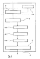
- the transmission method implemented by the invention aims to reduce the PAPR, and implements a new and inventive approach to step 105 in relation to the figure 1 .
- the signal c is calculated based on the characteristics of the signal x and using an optimization technique.
- the correction technique implements a step 20 of modifying, for a given symbol, the reference value of at least one subset of the pilot subcarriers, said corresponding subset in the case of the DVB-T nun to a subset of the pilot subcarriers dedicated to the channel estimation, using a correction datum c of the phase and / or the amplitude for each of the sub-carriers. pilot carriers of said subset so as to minimize the PAPR.
- this modification step 20 is composed of a step 21 for determining the correction data and a step 22 for modifying the reference value of the pilot subcarriers of said subassembly.
- N N d + N p .
- the optimization technique implements a convex optimization algorithm of the SOCP ( Second Order Cone Programming ) type.
- the simulation tools Yalmip and Tomlab are for example (but not limited to) tools that can be used under the software Matlab (trademark).
- the modification of the pilot carriers to reduce the PAPR is then performed (22) and consists in assigning to the pilot carriers of said subset of said pilot subcarriers dedicated to the estimation of the channel, the correction data that can reduce the PAPR.
- the operation takes place in the form of adding a signal in the time domain.
- the Figure 2B describes the implementation of step 21 according to two particular independent embodiments.
- a step 210 is previously implemented, determining said transition law applied for a data symbol or a series of data symbols.
- the transmitter and the receiver can operate with a single predetermined transition law (additive or multiplicative for all the symbols), not requiring the transmission of additional information.
- Step 210 optionally provides 211 binary information of choice Ib which may be transmitted within the signal, according to the particular embodiment shown on the Figure 2B .
- the algorithm calculates and delivers 214 the initial correction parameter C 0 applied to the first pilot subcarrier dedicated to the channel estimation P 0 of N r according to the frequency axis of said subset of said pilot subcarriers dedicated to the channel estimation on the one hand, and calculates and delivers the transition parameter ⁇ , defining the transition value of a pilot sub-carrier dedicated to the channel estimation P i to the pilot subcarrier dedicated to the next channel estimate P i + 1 along the frequency axis of said subset of said pilot subcarriers dedicated to channel estimation on the other hand.
- the set of C k is calculated 218, which marks the end of the step of determining the correction parameters 21.
- the algorithm calculates and delivers 216 the initial correction parameter C 0 applied to the first pilot subcarrier dedicated to the channel estimation P 0 of N r according to the frequency axis of said subset of said pilot subcarriers dedicated to the channel estimation on the one hand, and calculates and delivers the transition parameter ⁇ , defining the transition value of a pilot sub-carrier dedicated to the channel estimation P i to the pilot subcarrier dedicated to the next channel estimate P i + 1 along the frequency axis of said subset of said pilot subcarriers dedicated to channel estimation on the other hand.
- the set of C k is calculated 219, which marks the end of the step of determining the correction parameters 21.
- another variant consists in imposing an additional constraint on the optimization problem so that said correction data, said initial correction parameter and / or said transition parameter are defined with a predetermined pitch and / or selected from a set of predetermined values.
- phase correction data of said pilot subcarriers dedicated to the channel estimation one can consider a set of discrete correction values varying from 5 ° to 5 °, or that this set is chosen from a set of integer values.
- Annex A which is an integral part of the present description, proposes a practical example of embodiment of the invention according to whether an additive transition law is chosen. or multiplicative, and whether or not one of the correction parameters is fixed. In each of the illustrated cases, at least three distinct values of C k are obtained.
- the figure 3 illustrates an exemplary frame 30 of the multicarrier signal transmitted according to a particular embodiment of the invention.
- a frame comprises one or more headers 31 containing information known to the receiver and the transmitter (for example of size equivalent to 2 symbols) and symbols nmltiporter 33. These useful symbols 33 are each preceded by an interval of guard 32.
- each multicarrier symbol 33 is composed of a set of subcarriers, the set of useful subcarriers being composed of data subcarriers 35 and pilot subcarriers 36.
- the transmitter and the receiver can operate with a single predetermined transition law (additive or multiplicative for all the symbols), not requiring the transmission of additional information within the signal.
- the OFDM symbol detailed in figure 3 may optionally contain a binary information 34 of choice of the transition law chosen on transmission.
- the transmission of a signal containing for a given symbol ⁇ and the binary information representative of the choice of a transition law between two of said pilot subcarriers of said subassembly may optionally be considered to expedite the reception processing.
- the invention implements a reception method capable of performing a so-called "blind" estimation of the correction data assigned to the pilots dedicated to the channel estimation.
- the figure 4 illustrates the main steps of the method of receiving a multicarrier signal formed by a temporal succession of multicarrier symbols.
- the transmitter and the receiver can operate with a single predetermined transition law (additive or multiplicative for all symbols), not requiring then the existence of the binary information representative of the choice of a law of transition.
- an optional decoding step 410 is performed of at least the binary information representative of the choice of a transition law.
- the initial correction parameter C 0 applied to the first pilot subcarrier is obtained according to step 421 implementing equation (16). From C 0 and ⁇ , all of correction parameters applied to all other pilot subcarriers ( C k ) k ⁇ R rk ⁇ 0 is then obtained according to step 422 implementing equation (17).
- ⁇ represents the estimation error of ⁇ .
- the initial correction parameter C 0 applied to the first pilot subcarrier is obtained according to step 421 implementing equation (16a). From C 0 and ⁇ , the set of correction parameters applied to all the other pilot subcarriers ( C k ) k ⁇ R r, k ⁇ 0 is then obtained according to step 422 implementing equation (17a).
- the reception method implements following said steps of extraction, analysis, modification and channel estimation, a step of evaluation of the estimation error of the modification applied to said subset of said pilot subcarriers implementing a calculation of the mean squared error.
- This particular embodiment essentially makes it possible to evaluate the performance of the method in reception. Moreover, we can consider the transmission of a so-called "null" symbol, in order to evaluate the exact value of the frequency response of the channel, and integrate the estimation error for the channel estimation of the following symbol.
- Appendix A which forms an integral part of the present description, proposes a practical example of embodiment of the invention according to whether an additive or multiplicative transition law is chosen, and whether or not it is fixed. one of the correction parameters. This appendix also illustrates the steps and results obtained at the reception.
- AWGN type channel Gausian white noise channel
- Modulation 16QAM
- 4 FFT mode 2 k Guard Interval : 1/4 Number of data subcarriers : 1512 ⁇ max : 10 dB
- Eb / N0 7 dB
- AWGN type channel Gausian white noise channel
- Modulation 16QAM
- 4 FFT mode 2k Guard Interval : 1/4 Number of data subcarriers : 1512 ⁇ max : 10 dB
- Eb / N0 7 dB
Landscapes
- Engineering & Computer Science (AREA)
- Computer Networks & Wireless Communication (AREA)
- Signal Processing (AREA)
- Mobile Radio Communication Systems (AREA)
Claims (20)
- Mehrträger-Übertragungsverfahren eines für ein Quellensignal repräsentativen Signals, welches Symbole (33) aufweist, bestehend aus einer Menge von Nebenträgern, die gleichzeitig gesendet werden sollen und aus Steuernebenträgern, die mindestens einer Hilfs- und/oder Verbesserungsverarbeitung für das Dekodieren in mindestens einem Empfänger dienen sollen, sowie Daten-Nebenträger aufweisen,
wobei der Ort im Zeit-Frequenz-Raum und ein Referenzwert der besagten Steuernebenträger vom Empfänger bzw. von den Empfängern bekannt sind,
dadurch gekennzeichnet, dass das Verfahren eine Änderungsphase (20) des Referenzwertes von mindestens einer Teilmenge der besagten Steuernebenträger, für ein gegebenes Symbol (33), mit Hilfe eines Korrekturdatenwertes der Phase und/oder der Amplitude für jede der besagten Steuernebenträger der besagten Teilmenge aufweist, um das Verhältnis zwischen Spitzenleistung und mittlerer Leistung zu minimieren,
wobei die besagten Korrekturdaten mindestens drei verschiedene Werte annehmen, der Übergang zwischen den Werten zweier aufeinanderfolgender Steuernebenträger der besagten Teilmenge nach der Frequenzachse konstant ist, und der besagte Übergang nach einem multiplikativen oder additiven Überleitungsgesetz gegeben ist. - Übertragungsverfahren nach Anspruch 1, dadurch gekennzeichnet, dass die besagte Teilmenge der besagten Steuernebenträger solche aus mindestens einer der folgenden Kategorien umfasst:- Steuernebenträger, die der Synchronisierung dienen;- Steuernebenträger, die der Kanalschätzung dienen;- Signalisierungs-Nebenträger, die Informationen insbesondere bezüglich der Art der Modulation, der Übertragungsart und/oder der Kodierleistung umfassen.
- Übertragungsverfahren nach Anspruch 2, dadurch gekennzeichnet, dass mindestens einige der besagten Steuernebenträger der Kanalschätzung dienen und, dass es die folgenden Schritte anwendet:- Festlegung (21) der besagten Korrekturdaten, die für mindestens ein gegebenes Symbol folgendes umfassen:- einen untergeordneten Schritt zum Berechnen eines Ausgangs-Korrekturparameters (214, 216), der auf einen ersten Steuernebenträger P0 angewandt wird, welcher der Kanalschätzung nach der Frequenzachse der besagten Teilmenge besagter Steuernebenträger dienen, die selbst der Kanalschätzung dienen und/oder- einen untergeordneten Schritt zum Berechnen eines Übergangparameters (215, 217), der den Wert des Übergangs eines Steuernebenträgers, welcher der Kanalschätzung dient, zum Steuernebenträger Pi definiert, welcher der nachfolgenden Kanalschätzung nach der Frequenzachse der besagten Teilmenge von Steuernebenträgern Pi+1 dient, die selbst der Kanalschätzung dienen,- wobei der besagte anfängliche Korrekturparameter und der besagte Übergangsparameter so gewählt werden, dass das Verhältnis von Spitzenleistung zu mittlerer Leistung minimiert wird,- einen untergeordneten Schritt zum Erzielen der besagten Korrekturdaten (218, 219), ausgehend vom besagten Ausgangs-Korrekturparameter und dem besagten Übergangsparameter;- Änderung (22) des Referenzwertes der besagten Steuernebenträger, die der Kanalschätzung dienen, abhängig von den besagten Korrekturdaten, die korrigierte Werte liefern, die der Modulation der besagten Steuernebenträger dienen, welche selbst der Kanalschätzung der besagten Teilmenge dienen.
- Übertragungsverfahren nach Anspruch 3, dadurch gekennzeichnet, dass der besagte untergeordnete Schritt zum Erzielen, die besagten Korrekturdaten abhängig von dem besagten anfänglichen Korrekturparameter des Steuernebenträgers, welcher der Schätzung des Kanals mit der schwächsten Frequenz dient, sowie abhängig von der auf den Steuernebenträger angewandten Änderung, die der vorhergehenden Kanalschätzung nach der Frequenzachse dient und von dem besagten Übergangsparameter für die anderen, der Kanalschätzung dienenden Steuernebenträger, festlegt.
- Übertragungsverfahren nach einem der Ansprüche 1 bis 4, dadurch gekennzeichnet, dass die besagten Korrekturdaten, der besagte Ausgangs-Korrekturparameter und/oder der besagte Übergangsparameter mit Hilfe eines vorgegebenen Abstandes festgelegt wird bzw. werden und/oder aus einer Menge vorgegebener Werte gewählt wird bzw. werden.
- Übertragungsverfahren nach einem der Ansprüche 1 bis 5, dadurch gekennzeichnet, dass es einen vorhergehenden Schritt (210) zur Wahl des besagten Übergangsgesetzes für ein gegebenes Symbol oder eine Reihe gegebener Symbole anwendet.
- Übertragungsverfahren nach Anspruch 6, dadurch gekennzeichnet, dass der vorhergehende Schritt zur Wahl des besagten Übergangsgesetzes eine binäre Auswahlinformation liefert (211) und dadurch, dass es einen Übertragungsschritt der besagten Auswahlinformation anwendet.
- Übertragungsverfahren nach einem der Ansprüche 1 bis 7, dadurch gekennzeichnet, dass ein multiplikatives Übergangsgesetz die auf den besagten Steuernebenträger Pi+1 anzuwendende Änderung festlegt, welche der Kanalschätzung dient, durch Multiplizieren eines auf den besagten vorhergehenden, der Kanalschätzung nach der Frequenzachse dienenden Steuernebenträgers Pi angewandten Korrekturparameters Ci, mit dem besagten Übergangsparameter.
- Übertragungsverfahren nach einem der Ansprüche 1 bis 7, dadurch gekennzeichnet, dass ein additives Übergangsgesetz die auf den besagten Steuernebenträger Pi+1 anzuwendende Änderung festlegt, welche der Kanalschätzung dient, durch Addieren eines auf den besagten vorhergehenden, der Kanalschätzung nach der Frequenzachse dienenden Steuernebenträgers angewandten Korrekturparameters Ci, mit dem besagten Übergangsparameter.
- Mehrträger Übertragungsvorrichtung eines für ein Quellensignal repräsentativen Signals, welches Symbole (33) aufweist, bestehend aus einer Menge von Nebenträgern, die gleichzeitig gesendet werden sollen und aus Steuernebenträgern, die mindestens einer Hilfs- und/oder Verbesserungsverarbeitung für das Dekodieren in mindestens einem Empfänger dienen sollen, sowie Daten-Nebenträger aufweisen,
wobei der Ort im Zeit-Frequenz-Raum und ein Referenzwert der besagten Steuernebenträger vom Empfänger bzw. von den Empfängern bekannt sind,
dadurch gekennzeichnet, dass die Vorrichtung über Mittel zum Ändern des Referenzwertes von mindestens einer Teilmenge der besagten Steuernebenträger, für ein gegebenes Symbol, mit Hilfe eines Korrekturdatenwertes der Phase und/oder der Amplitude für jede der besagten Steuernebenträger der besagten Teilmenge aufweist, um das Verhältnis zwischen Spitzenleistung und mittlerer Leistung zu minimieren,
wobei die besagten Korrekturdaten mindestens drei verschiedene Werte annehmen, der Übergang zwischen den Werten zweier aufeinanderfolgender Nebenträger der besagten Teilmenge nach der Frequenzachse konstant ist, und der besagte Übergang nach einem multiplikativen oder additiven Überleitungsgesetz gegeben ist. - Mehrträgersignal, das mittels des Übertragungsverfahren nach einem der Ansprüche 2 bis 9 erzielt wird, welches Symbole (33) aufweist, die aus einer Menge von Nebenträgern bestehen und gleichzeitig gesendet werden sollen, und aus Steuernebenträgern, die mindestens einer Hilfs- und/oder Verbesserungsverarbeitung für das Dekodieren in mindestens einem Empfänger dienen sollen sowie Daten-Nebenträger aufweisen,
wobei der Ort im Zeit-Frequenz-Raum und ein Referenzwert der besagten Steuernebenträger vom Empfänger bzw. von den Empfängern bekannt sind,
dadurch gekennzeichnet, dass für ein gegebenes Symbol (33), der Referenzwert von mindestens einer Teilmenge von Steuernebenträgern, die der Kanalschätzung dienen, geändert wird, mit Hilfe eines Korrekturparameters der Phase und/oder der Amplitude einer jeden der besagten Steuernebenträger der besagten Teilmenge, so dass das Verhältnis von Spitzenleistung zu mittlerer Leistung minimiert wird,
wobei die besagten Korrekturparameter mindestens drei verschiedene Werte annehmen, der Übergang zwischen den Werten zweier aufeinanderfolgender Nebenträger der besagten Teilmenge nach der Frequenzachse konstant ist, und der besagte Übergang nach einem multiplikativen oder additiven Überleitungsgesetz vorgegeben ist. - Signal nach Anspruch 11, dadurch gekennzeichnet, dass es mindestens eine Hilfsinformation für den Empfang aufweist, unter den Informationen aus der Gruppe, die folgendes umfasst:- eine für den besagten anfänglichen Korrekturparameter repräsentative Information;- eine für den besagten Übergangsparameter repräsentative Information;- eine Binärinformation, die repräsentativ ist für die Auswahl eines Übergangsgesetzes zwischen zwei der besagten Steuernebenträger, welche der Kanalschätzung der besagten Teilmenge dienen.
- Produkt, bestehend aus einem EDV-Programm, das von einem Kommunikationsnetz heruntergeladen und/oder auf einem durch einen Rechner lesbaren und/oder durch einen Prozessor zu bearbeitenden Datenträger gespeichert ist, dadurch gekennzeichnet, dass es über Programmcodeanweisungen verfügt, um das Übertragungsverfahren nach mindestens einem der Ansprüche 1 bis 9 anzuwenden, wenn es auf einem Rechner ausgeführt wird.
- Empfangsverfahren eines Signals nach einem der Ansprüche 11 oder 12, das von mindestens einem Sender über einen Sendekanal gesendet wird,
wobei das besagte Signal aus einer zeitlichen Reihenfolge von Symbolen gebildet wird, die aus einer Menge von Nebenträgern bestehen und gleichzeitig gesendet werden sollen, und Steuernebenträger umfasst, die mindestens einer Hilfs- und/oder Verbesserungsverarbeitung für das Dekodieren in mindestens einem Empfänger dienen sollen sowie aus Daten-Nebenträgern gebildet wird,
wobei der Ort im Zeit-Frequenz-Raum und ein Referenzwert der besagten Steuernebenträger vom Empfänger bzw. von den Empfängern bekannt sind,
wobei der Referenzwert von mindestens einer Teilmenge der besagten Steuernebenträger, die der Kanalschätzung dienen, für ein gegebenes Symbol mit Hilfe eines Korrekturparameters der Phase und/oder der Amplitude einer jeden der besagten Steuernebenträger der besagten Teilmenge so geändert werden, dass das Verhältnis zwischen Spitzenleistung und mittlerer Leistung minimiert wird,
wobei die besagten Korrekturparameter mindestens drei verschiedene Werte annehmen, der Übergang zwischen den Werten zweier aufeinanderfolgender Steuernebenträger der besagten Teilmenge nach der Frequenzachse konstant ist, und der besagte Übergang nach einem multiplikativen oder additiven Überleitungsgesetz gegeben ist,
wobei das Verfahren die folgenden Schritte aufweist:- Extrahieren (41) der empfangenen Informationen, die jede der Nebenträger aus der besagten Teilmenge von Nebenträgern modulieren;- Analysieren (42) der Menge der besagten empfangenen Informationen, um eine Abschätzung der besagten Korrekturdaten festzulegen;- Schätzen (43) des Übertragungskanals, ausgehend von den besagten Korrekturdaten. - Empfangsverfahren nach Anspruch 14, dadurch gekennzeichnet, dass der besagte analytische Schritt folgendes umfasst:- einen Schritt zur Festlegung (421) eines Übergangsparameters, der den Übergangswert von einem der Kanalschätzung dienenden Steuernebenträgers Pi, zu dem Steuernebenträger Pi+ definiert, welcher der nachfolgenden Kanalschätzung 1 nach der Frequenzachse der besagten Teilmenge besagter Steuernebenträger, die der Kanalschätzung dienen sollen, durch Analyse der Menge der Übergänge dient und/oder,- einen Schritt zur Festlegung (422) eines anfänglichen Korrekturparameters C0, der auf einen ersten Steuernebenträger P0 angewandt wird, welcher der Kanalschätzung nach der Frequenzachse der besagten Teilmenge besagter Steuernebenträger dienen, die selbst der Kanalschätzung dienen, abhängig vom Wert von mindestens einem der besagten Steuernebenträger aus der besagten Teilmenge von besagten Steuernebenträgern, die der Kanalschätzung dienen, und abhängig von dem Übergangsparameter;- einen Schritt (423) zum Festlegen der Korrekturparameter, die auf allen anderen Steuernebenträgern Pi,i≠0 angewendet werden, welche der Kanalschätzung nach der Frequenzachse der besagten Teilmenge von besagten, der Kanalschätzung dienenden Steuernebenträgern dienen, abhängig von dem Wert des anfänglichen Korrekturparameters C0, der auf den ersten Steuernebenträger P0 angewendet wird, welcher der Kanalschätzung dient, und abhängig von dem Übergangsparameter.
- Empfangsverfahren nach Anspruch 15, dadurch gekennzeichnet, dass mindestens einer der besagten Festlegungsschritte die Bildung eines Mittelwertes anwendet.
- Empfangsverfahren nach einem der Ansprüche 15 oder 16, dadurch gekennzeichnet, dass für mindestens einen der besagten Festlegungsschritte der besagte anfänglichen Korrekturparameter und/oder der besagte Übergangsparameter mit Hilfe eines vorgegebenen Abstandes festgelegt wird bzw. werden und/oder aus einer Menge vorgegebener Werte gewählt wird bzw. werden.
- Empfangsverfahren nach einem der Ansprüche 14 bis 17, dadurch gekennzeichnet, dass es einen vorhergehenden Dekodierungsschritt von mindestens einer Information aus der folgendes umfassenden Gruppe aufweist:- eine für den besagten anfänglichen Korrekturparameter repräsentative Information;- eine für den besagten Übergangsparameter repräsentative Information;- eine Binärinformation, die repräsentativ ist für die Auswahl eines Übergangsgesetzes zwischen zwei der besagten Steuernebenträger, welche der Kanalschätzung der besagten Teilmenge dienen.
- Empfangsvorrichtung eines Signals nach einem der Ansprüche 11 oder 12, das von mindestens einem Sender über einen Sendekanal gesendet wird,
wobei das besagte Signal aus einer zeitlichen Reihenfolge von Symbolen gebildet wird, die aus einer Menge von Nebenträgern bestehen und gleichzeitig gesendet werden sollen, und Steuernebenträger umfasst, die mindestens einer Hilfs- und/oder Verbesserungsverarbeitung für das Dekodieren in mindestens einem Empfänger dienen sollen, sowie aus Daten-Nebenträgern gebildet wird,
wobei der Ort im Zeit-Frequenz-Raum und ein Referenzwert der besagten Steuernebenträger vom Empfänger bzw. von den Empfängern bekannt sind,
wobei der Referenzwert von mindestens einer Teilmenge der besagten, der Kanalschätzung dienenden Steuernebenträger, für ein gegebenes Symbol mit Hilfe eines Korrekturparameters der Phase und/oder der Amplitude einer jeden der besagten Steuernebenträger der besagten Teilmenge so geändert werden, dass das Verhältnis zwischen Spitzenleistung und mittlerer Leistung minimiert wird,
wobei die besagten Korrekturparameter mindestens drei verschiedene Werte annehmen, der Übergang zwischen den Werten zweier aufeinanderfolgender Steuernebenträger der besagten Teilmenge nach der Frequenzachse konstant ist und der besagte Übergang nach einem multiplikativen oder additiven Überleitungsgesetz gegeben ist,
dadurch gekennzeichnet, dass sie folgendes umfasst:- Mittel zum Extrahieren der empfangenen Informationen, die jeden Nebenträger aus der besagten Teilmenge von Nebenträgern modulieren;- Mittel zum Analysieren der Menge der besagten empfangenen Informationen, um eine Abschätzung der besagten Korrekturdaten festzulegen;- Mittel zum Schätzen des Übertragungskanals, ausgehend von den besagten Korrekturdaten. - Produkt, bestehend aus einem EDV-Programm, das von einem Kommunikationsnetz heruntergeladen und/oder auf einem durch einen Rechner lesbaren und/oder durch einen Prozessor zu bearbeitenden Datenträger gespeichert ist, dadurch gekennzeichnet, dass es über Programmcodeanweisungen verfügt, um das Empfangsverfahren nach mindestens einem der Ansprüche 14 bis 18 anzuwenden, wenn es auf einem Rechner ausgeführt wird.
Applications Claiming Priority (2)
| Application Number | Priority Date | Filing Date | Title |
|---|---|---|---|
| FR0952964A FR2945172B1 (fr) | 2009-05-04 | 2009-05-04 | Procede et dispositif de transmission d'un signal multiporteuse reduisant le rapport puissance crete a puissance moyenne, programme, signal, procede et dispositif de reception correspondants |
| PCT/EP2010/056053 WO2010128057A1 (fr) | 2009-05-04 | 2010-05-04 | Reduction du rapport puissance crete a puissance moyenne dans un signal multiporteuse |
Publications (2)
| Publication Number | Publication Date |
|---|---|
| EP2428012A1 EP2428012A1 (de) | 2012-03-14 |
| EP2428012B1 true EP2428012B1 (de) | 2014-03-12 |
Family
ID=41402398
Family Applications (1)
| Application Number | Title | Priority Date | Filing Date |
|---|---|---|---|
| EP10722977.5A Not-in-force EP2428012B1 (de) | 2009-05-04 | 2010-05-04 | Verringerung des Verhältnisses von Spitzen-zu-Durchschnittsleistung in einem Mehrträgersignal |
Country Status (7)
| Country | Link |
|---|---|
| US (1) | US8804861B2 (de) |
| EP (1) | EP2428012B1 (de) |
| JP (1) | JP5632457B2 (de) |
| CN (1) | CN102461108B (de) |
| ES (1) | ES2470743T3 (de) |
| FR (1) | FR2945172B1 (de) |
| WO (1) | WO2010128057A1 (de) |
Families Citing this family (12)
| Publication number | Priority date | Publication date | Assignee | Title |
|---|---|---|---|---|
| US9401823B2 (en) * | 2013-11-26 | 2016-07-26 | Plusn Llc | System and method for radio frequency carrier aggregation |
| KR102302600B1 (ko) * | 2014-08-07 | 2021-09-15 | 원 미디어, 엘엘씨 | 유연한 직교 주파수 분할 멀티플렉싱 물리 전송 데이터 프레임의 동적 구성 방법 |
| CN111628854A (zh) | 2014-08-07 | 2020-09-04 | 相干逻辑公司 | 多分区无线电帧 |
| CN104168246B (zh) * | 2014-08-26 | 2017-08-25 | 电子科技大学 | 一种基于迭代平均处理的导频设计方法 |
| KR102269498B1 (ko) * | 2015-01-28 | 2021-06-28 | 삼성전자 주식회사 | 다중 반송파 통신 시스템에서 전력을 제어하는 방법 및 장치 |
| WO2016127324A1 (zh) * | 2015-02-10 | 2016-08-18 | 华为技术有限公司 | 一种降低峰均比的方法、装置、设备和系统 |
| FR3036014B1 (fr) * | 2015-05-06 | 2017-05-26 | Inst Nat Des Sciences Appliquees (Insa) | Procede et dispositif de transmission d'un signal multiporteuse programme et signal, correspondants. |
| CN107667490B (zh) * | 2015-07-27 | 2019-10-25 | Lg电子株式会社 | 用于发送和接收广播信号的设备和方法 |
| CN110581819B (zh) * | 2018-06-08 | 2022-02-18 | 中国移动通信集团有限公司 | 一种降低papr的方法、装置、电子设备及存储介质 |
| US11916679B2 (en) * | 2019-09-11 | 2024-02-27 | Silicon Laboratories Inc. | Apparatus and method to reduce spectral peaks in Bluetooth communications |
| US20240080159A1 (en) * | 2022-09-06 | 2024-03-07 | Qualcomm Incorporated | Pilot symbols having pilot signaling and peak-to-average-power-ratio signaling |
| WO2024138599A1 (zh) * | 2022-12-30 | 2024-07-04 | 华为技术有限公司 | 一种通信方法及相关设备 |
Family Cites Families (45)
| Publication number | Priority date | Publication date | Assignee | Title |
|---|---|---|---|---|
| US6449303B2 (en) * | 2000-06-20 | 2002-09-10 | Powerwave Technologies, Inc. | System and method for peak power reduction in multiple carrier communications systems |
| US7418043B2 (en) * | 2000-07-19 | 2008-08-26 | Lot 41 Acquisition Foundation, Llc | Software adaptable high performance multicarrier transmission protocol |
| US7099299B2 (en) * | 2002-03-04 | 2006-08-29 | Agency For Science, Technology And Research | CDMA system with frequency domain equalization |
| KR100575980B1 (ko) * | 2002-12-24 | 2006-05-02 | 삼성전자주식회사 | 직교 주파수 분할 다중 방식을 사용하는 통신 시스템에서피크대 평균 전력비를 최소화시키는 장치 및 방법 |
| KR100933115B1 (ko) * | 2003-09-09 | 2009-12-21 | 삼성전자주식회사 | 직교 주파수 분할 다중 통신 시스템에서 피크 전력 대 평균 전력비의 감소를 위한 장치 및 방법 |
| RU2333606C2 (ru) * | 2004-03-05 | 2008-09-10 | Самсунг Электроникс Ко., Лтд. | Устройство и способ передачи/приема пилот-сигнала в системе связи, использующей схему ofdm |
| KR100688118B1 (ko) * | 2004-04-23 | 2007-02-28 | 삼성전자주식회사 | 직교 주파수 분할 다중 통신 시스템에서 피크 전력 대평균 전력비를 감소시키기 위한 장치 및 방법 |
| JP4429795B2 (ja) * | 2004-05-06 | 2010-03-10 | 株式会社エヌ・ティ・ティ・ドコモ | 無線通信システム、無線送信機及び無線受信機 |
| JP4398791B2 (ja) * | 2004-05-25 | 2010-01-13 | 株式会社エヌ・ティ・ティ・ドコモ | 送信機および送信制御方法 |
| US7583586B2 (en) * | 2004-07-02 | 2009-09-01 | Samsung Electronics Co., Ltd | Apparatus and method for transmitting/receiving pilot signal in communication system using OFDM scheme |
| JP4153906B2 (ja) * | 2004-07-09 | 2008-09-24 | 株式会社東芝 | 通信装置、送信方法及び受信方法 |
| KR100754617B1 (ko) * | 2004-10-11 | 2007-09-05 | 삼성전자주식회사 | 직교 주파수 분할 다중화 통신 시스템에서 피크대 평균전력비를 최소화시키기 위한 장치 및 방법 |
| JP4619797B2 (ja) * | 2005-01-14 | 2011-01-26 | 富士通株式会社 | 無線通信システム及び無線通信装置 |
| JP2006229746A (ja) * | 2005-02-18 | 2006-08-31 | Japan Telecom Co Ltd | ピーク電力の低減方法並びに装置、及びこれを用いた移動体通信システム、並びにこの移動体通信システムに用いる送信機 |
| US7668266B2 (en) * | 2005-03-18 | 2010-02-23 | Georgia Tech Research Corporation | Crest factor reduction in OFDM using blind selected pilot tone modulation |
| US8189714B2 (en) * | 2005-05-04 | 2012-05-29 | Rockstar Bidco, LP | Wireless feedback system and method |
| US20070004465A1 (en) * | 2005-06-29 | 2007-01-04 | Aris Papasakellariou | Pilot Channel Design for Communication Systems |
| US7916694B2 (en) * | 2005-07-19 | 2011-03-29 | Broadcom Corporation | Method and system reducing peak to average power ratio (PAPR) in a communication network |
| EP1746720B1 (de) * | 2005-07-21 | 2008-04-16 | Alcatel Lucent | Adaptives digitales Vorentzerrungssystem |
| US20070071120A1 (en) * | 2005-09-26 | 2007-03-29 | Shilpa Talwar | Peak to average power reduction using channel state information |
| EP1791313B1 (de) * | 2005-10-25 | 2008-08-20 | Fujitsu Ltd. | Kommunikationssysteme und -verfahren mit Selected Mapping (SLM)-Technik für OFDM Signale |
| EP1780966B1 (de) * | 2005-10-25 | 2008-04-30 | Fujitsu Limited | Blind Selective Mapping (SLM) unter Verwendung von Pilotsignalen |
| EP1958408B1 (de) * | 2005-12-06 | 2019-11-06 | Microsoft Technology Licensing, LLC | Vorrichtung und verfahren zum senden von daten unter verwendung mehrerer träger |
| CN101502069B (zh) * | 2006-02-09 | 2012-10-17 | 阿尔戴尔半导体有限公司 | 频分多址系统中的低峰均功率比传输 |
| CN1984110B (zh) * | 2006-04-24 | 2011-04-20 | 华为技术有限公司 | 降低峰均比的方法和具有低峰均比的正交频分复用系统 |
| JP2007329588A (ja) * | 2006-06-06 | 2007-12-20 | Fujitsu Ltd | 送信機及び送信方法 |
| WO2008032407A1 (fr) * | 2006-09-15 | 2008-03-20 | Fujitsu Limited | Appareil et procédé pour transmettre des signaux au moyen d'un système à porteuses multiples |
| US7664010B2 (en) * | 2006-09-21 | 2010-02-16 | Sharp Laboratories Of America, Inc. | Systems and methods for combining reference and data signals to reduce peak to average power ratio for coherent communication systems |
| US7746766B2 (en) * | 2006-09-21 | 2010-06-29 | Sharp Laboratories Of America, Inc. | Systems and methods for obtaining an optimum transmission format of reference signals to maximize capacity and minimize peak to average power ratio |
| US8073073B2 (en) * | 2006-10-30 | 2011-12-06 | Quantenna Communications, Inc. | Optimized clipping for peak-to-average power ratio reduction |
| US7949059B2 (en) * | 2006-11-09 | 2011-05-24 | University College Dublin, National University Of Ireland, Dublin | Peak-to-average-power reduction of OFDM signals |
| GB2444100B (en) * | 2006-11-24 | 2009-10-28 | Imagination Tech Ltd | Channel estimation and equalization in ofdm receivers |
| US8098744B2 (en) * | 2007-01-03 | 2012-01-17 | Freescale Semiconductor, Inc. | Reducing a peak-to-average ratio of a signal using filtering |
| US8131218B2 (en) * | 2007-04-13 | 2012-03-06 | General Dynamics C4 Systems, Inc. | Methods and apparatus for wirelessly communicating signals that include embedded synchronization/pilot sequences |
| KR20080106832A (ko) * | 2007-06-04 | 2008-12-09 | 삼성전자주식회사 | 직교 주파수 분할 다중 시스템의 평균전력 대 최대전력비감소 장치 및 방법 |
| JP4871813B2 (ja) * | 2007-08-28 | 2012-02-08 | 株式会社日立製作所 | 無線通信装置、無線通信方法及びピーク抑圧方法 |
| US7986738B2 (en) * | 2007-10-19 | 2011-07-26 | Redpine Signals, Inc | Peak to average power ratio reduction apparatus and method for a wireless OFDM transmitter |
| US8379752B2 (en) * | 2008-03-19 | 2013-02-19 | General Dynamics C4 Systems, Inc. | Methods and apparatus for multiple-antenna communication of wireless signals with embedded synchronization/pilot sequences |
| US8571000B2 (en) * | 2008-08-08 | 2013-10-29 | Qualcomm Incorporated | Peak-to-average power ratio (PAPR) reduction scheme for wireless communication |
| US8189697B2 (en) * | 2008-10-01 | 2012-05-29 | Harris Corporation | Orthogonal frequency division multiplexing (OFDM) communications device and method that incorporates low PAPR preamble and receiver channel estimate circuit |
| US20100091900A1 (en) * | 2008-10-10 | 2010-04-15 | Qualcomm Incorporated | Apparatus and method for ofdm modulated signal transmission with reduced peak-to-average power ratio |
| GB0818989D0 (en) * | 2008-10-16 | 2008-11-26 | Univ Glasgow | A telecommunications method and system |
| EP2345221B1 (de) * | 2008-10-31 | 2012-09-19 | Telecom Italia S.p.A. | PAPR-Reduktion in einer Mehrträgerübertragung |
| US8744009B2 (en) * | 2009-09-25 | 2014-06-03 | General Dynamics C4 Systems, Inc. | Reducing transmitter-to-receiver non-linear distortion at a transmitter prior to estimating and cancelling known non-linear distortion at a receiver |
| US8355466B2 (en) * | 2009-09-25 | 2013-01-15 | General Dynamics C4 Systems, Inc. | Cancelling non-linear power amplifier induced distortion from a received signal by moving incorrectly estimated constellation points |
-
2009
- 2009-05-04 FR FR0952964A patent/FR2945172B1/fr not_active Expired - Fee Related
-
2010
- 2010-05-04 CN CN201080023443.2A patent/CN102461108B/zh not_active Expired - Fee Related
- 2010-05-04 EP EP10722977.5A patent/EP2428012B1/de not_active Not-in-force
- 2010-05-04 WO PCT/EP2010/056053 patent/WO2010128057A1/fr active Application Filing
- 2010-05-04 US US13/318,853 patent/US8804861B2/en not_active Expired - Fee Related
- 2010-05-04 ES ES10722977.5T patent/ES2470743T3/es active Active
- 2010-05-04 JP JP2012509017A patent/JP5632457B2/ja not_active Expired - Fee Related
Non-Patent Citations (5)
| Title |
|---|
| AGGARWAL A ET AL: "A convex interior-point method for optimal OFDM PAR reduction", COMMUNICATIONS, 2005. ICC 2005. 2005 IEEE INTERNATIONAL CONFERENCE ON SEOUL, KOREA 16-20 MAY 2005, PISCATAWAY, NJ, USA,IEEE, vol. 3, 16 May 2005 (2005-05-16), pages 1985 - 1990, XP010826219, ISBN: 978-0-7803-8938-0, DOI: 10.1109/ICC.2005.1494686 * |
| AGGARWAL A ET AL: "Minimizing the peak-to-average power ratio of OFDM signals via convex optimization", GLOBECOM'03. 2003 - IEEE GLOBAL TELECOMMUNICATIONS CONFERENCE. CONFERENCE PROCEEDINGS. SAN FRANCISCO, CA, DEC. 1 - 5, 2003; [IEEE GLOBAL TELECOMMUNICATIONS CONFERENCE], NEW YORK, NY : IEEE, US, vol. 4, 1 December 2003 (2003-12-01), pages 2385 - 2389, XP010677782, ISBN: 978-0-7803-7974-9, DOI: 10.1109/GLOCOM.2003.1258662 * |
| ANH TAI HO ET AL: "A novel combined PAPR reduction and channel estimation approach for OFDM systems", BROADBAND MULTIMEDIA SYSTEMS AND BROADCASTING (BMSB), 2010 IEEE INTERNATIONAL SYMPOSIUM ON, IEEE, PISCATAWAY, NJ, USA, 24 March 2010 (2010-03-24), pages 1 - 5, XP031675535, ISBN: 978-1-4244-4461-8 * |
| MAHAFENO I M ET AL: "Peak-to-average power ratio reduction using second order cone programming based tone reservation for terrestrial digital video broadcasting systems", IET COMMUNICATIONS,, vol. 3, no. 7, 6 July 2009 (2009-07-06), pages 1250 - 1261, XP006033378, ISSN: 1751-8636, DOI: 10.1049/IET-COM:20080372 * |
| SIDKIETA ZABRE ET AL: "SOCP Approach for OFDM Peak-to-Average Power Ratio Reduction in the Signal Adding Context", SIGNAL PROCESSING AND INFORMATION TECHNOLOGY, 2006 IEEE INTERNATIONAL SYMPOSIUM ON, IEEE, PI, 1 August 2006 (2006-08-01), pages 834 - 839, XP031002542, ISBN: 978-0-7803-9753-8 * |
Also Published As
| Publication number | Publication date |
|---|---|
| FR2945172A1 (fr) | 2010-11-05 |
| US20120140836A1 (en) | 2012-06-07 |
| WO2010128057A1 (fr) | 2010-11-11 |
| FR2945172B1 (fr) | 2011-04-22 |
| CN102461108A (zh) | 2012-05-16 |
| JP5632457B2 (ja) | 2014-11-26 |
| JP2012526438A (ja) | 2012-10-25 |
| CN102461108B (zh) | 2015-02-04 |
| EP2428012A1 (de) | 2012-03-14 |
| ES2470743T3 (es) | 2014-06-24 |
| US8804861B2 (en) | 2014-08-12 |
Similar Documents
| Publication | Publication Date | Title |
|---|---|---|
| EP2428012B1 (de) | Verringerung des Verhältnisses von Spitzen-zu-Durchschnittsleistung in einem Mehrträgersignal | |
| EP2253114B1 (de) | Verfahren zum senden und empfangen eines mehrträgersignals mit verweilzeit und entsprechende computersoftwareprodukte, sende- und empfangsgeräte sowie signal | |
| EP2879341B1 (de) | Methode zur Kanalabschätzung für FBMC-Telekommunikationssystem | |
| EP2156590B1 (de) | Senden und empfangen von mehrträger-spreizspektrumsignalen | |
| EP1969792B1 (de) | Verfahren und vorrichtung zur dynamischen verwürfelung | |
| EP2039095B1 (de) | Verfahren zum Senden und Empfangen eines Mehrträgersignals unter Durchführung einer Kanalschätzung sowie entsprechende Geräte und Computerprogramme | |
| EP3042480B1 (de) | Verfahren und gerät zur übertragung von komplexen datensymbolblocks, verfahren und gerät zur empfang und entsprechende computer programme | |
| EP3146687B1 (de) | Verfahren zum senden eines signals mit einer präambel und entsprechende vorrichtungen, signal mit entsprechender präambel zur synchronisation eines empfängers | |
| EP1987645A1 (de) | Übertragungsverfahren mit für einen mehrträgersender emittierter optimaler leistungszuweisung | |
| EP3292668B1 (de) | Reduktion von spitzen-zu-durchschnittsleistung in einem mehrträgersignal | |
| WO2006117268A1 (fr) | Procédé de décodage itératif d'un signal ofdm/oqam utilisant des symboles à valeurs complexes, dispositif et programme d'ordinateur correspondants | |
| EP2039094B1 (de) | Verfahren zum Senden und Empfangen eines Mehrträgersignals mit isolierten Piloten sowie entsprechende Geräte und Computerprogramme | |
| FR2903833A1 (fr) | Procedes d'emission et de reception d'un signal multiporteuse mettant en oeuvre une estimation de canal, dispositifs et produits programme d'ordinateur correspondants. | |
| EP3125486A1 (de) | Papr reduzierung eines einzelträger sendesignal | |
| EP2219333B1 (de) | Mehrträgersignalübertragungsverfahren und -vorrichtung zur PAPR-Reduzierung sowie zugehöriges Programm | |
| WO2014128176A2 (fr) | Procedes et dispositifs de transmission et de reception d'un signal multiporteuse reduisant le rapport puissance crête à puissance moyenne, programme et signal correspondants | |
| FR3004040A1 (fr) | Procede de transmission d'un signal multiporteuse, dispositif de transmission et programme d'ordinateur correspondants | |
| WO2007090995A2 (fr) | Procede de reception d' un signal mettant en oeuvre une estimation d' un canal de propagation, dispositif de reception et produit programme d' ordinateur corres pondants | |
| WO2009150187A1 (fr) | Procédé et dispositif de transmission d'un signal multiporteuse réduisant le rapport puissance crête à puissance moyenne, procédé et dispositif de réception, programmes et signal correspondants | |
| FR3116169A1 (fr) | Procédé de télécommunication avec codage binaire à symboles à répétition et dispositifs correspondants | |
| FR2913835A1 (fr) | Traitement d'un signal de communication, avant amplification en modulation multi-porteuses | |
| WO2014188143A1 (fr) | Procede de transmission d'un signal multi porteuse avec reduction du papr du signal émis | |
| WO2008007029A2 (fr) | Procedes d' emission et de reception d ' un signal multiporteuse de type oqam |
Legal Events
| Date | Code | Title | Description |
|---|---|---|---|
| PUAI | Public reference made under article 153(3) epc to a published international application that has entered the european phase |
Free format text: ORIGINAL CODE: 0009012 |
|
| 17P | Request for examination filed |
Effective date: 20111103 |
|
| AK | Designated contracting states |
Kind code of ref document: A1 Designated state(s): AL AT BE BG CH CY CZ DE DK EE ES FI FR GB GR HR HU IE IS IT LI LT LU LV MC MK MT NL NO PL PT RO SE SI SK SM TR |
|
| RIN1 | Information on inventor provided before grant (corrected) |
Inventor name: HELARD, JEAN-FRANCOIS Inventor name: LOUET, YVES Inventor name: MASINJARA MAHAFENO, IRENE |
|
| DAX | Request for extension of the european patent (deleted) | ||
| 17Q | First examination report despatched |
Effective date: 20120803 |
|
| GRAP | Despatch of communication of intention to grant a patent |
Free format text: ORIGINAL CODE: EPIDOSNIGR1 |
|
| INTG | Intention to grant announced |
Effective date: 20130731 |
|
| INTG | Intention to grant announced |
Effective date: 20130805 |
|
| GRAS | Grant fee paid |
Free format text: ORIGINAL CODE: EPIDOSNIGR3 |
|
| GRAA | (expected) grant |
Free format text: ORIGINAL CODE: 0009210 |
|
| AK | Designated contracting states |
Kind code of ref document: B1 Designated state(s): AL AT BE BG CH CY CZ DE DK EE ES FI FR GB GR HR HU IE IS IT LI LT LU LV MC MK MT NL NO PL PT RO SE SI SK SM TR |
|
| RAP1 | Party data changed (applicant data changed or rights of an application transferred) |
Owner name: INSTITUT NATIONAL DES SCIENCES APPLIQUEES DE RENNE Owner name: CNRS CENTRE NATIONAL DE LA RECHERCHE SCIENTIFIQUE |
|
| REG | Reference to a national code |
Ref country code: GB Ref legal event code: FG4D Free format text: NOT ENGLISH |
|
| REG | Reference to a national code |
Ref country code: CH Ref legal event code: EP |
|
| REG | Reference to a national code |
Ref country code: AT Ref legal event code: REF Ref document number: 656925 Country of ref document: AT Kind code of ref document: T Effective date: 20140315 |
|
| REG | Reference to a national code |
Ref country code: IE Ref legal event code: FG4D Free format text: LANGUAGE OF EP DOCUMENT: FRENCH |
|
| REG | Reference to a national code |
Ref country code: DE Ref legal event code: R096 Ref document number: 602010014201 Country of ref document: DE Effective date: 20140424 |
|
| REG | Reference to a national code |
Ref country code: ES Ref legal event code: FG2A Ref document number: 2470743 Country of ref document: ES Kind code of ref document: T3 Effective date: 20140624 |
|
| REG | Reference to a national code |
Ref country code: NL Ref legal event code: VDEP Effective date: 20140312 |
|
| PG25 | Lapsed in a contracting state [announced via postgrant information from national office to epo] |
Ref country code: LT Free format text: LAPSE BECAUSE OF FAILURE TO SUBMIT A TRANSLATION OF THE DESCRIPTION OR TO PAY THE FEE WITHIN THE PRESCRIBED TIME-LIMIT Effective date: 20140312 Ref country code: NO Free format text: LAPSE BECAUSE OF FAILURE TO SUBMIT A TRANSLATION OF THE DESCRIPTION OR TO PAY THE FEE WITHIN THE PRESCRIBED TIME-LIMIT Effective date: 20140612 |
|
| REG | Reference to a national code |
Ref country code: AT Ref legal event code: MK05 Ref document number: 656925 Country of ref document: AT Kind code of ref document: T Effective date: 20140312 |
|
| REG | Reference to a national code |
Ref country code: LT Ref legal event code: MG4D |
|
| PG25 | Lapsed in a contracting state [announced via postgrant information from national office to epo] |
Ref country code: SE Free format text: LAPSE BECAUSE OF FAILURE TO SUBMIT A TRANSLATION OF THE DESCRIPTION OR TO PAY THE FEE WITHIN THE PRESCRIBED TIME-LIMIT Effective date: 20140312 Ref country code: FI Free format text: LAPSE BECAUSE OF FAILURE TO SUBMIT A TRANSLATION OF THE DESCRIPTION OR TO PAY THE FEE WITHIN THE PRESCRIBED TIME-LIMIT Effective date: 20140312 Ref country code: CY Free format text: LAPSE BECAUSE OF FAILURE TO SUBMIT A TRANSLATION OF THE DESCRIPTION OR TO PAY THE FEE WITHIN THE PRESCRIBED TIME-LIMIT Effective date: 20140312 |
|
| PG25 | Lapsed in a contracting state [announced via postgrant information from national office to epo] |
Ref country code: LV Free format text: LAPSE BECAUSE OF FAILURE TO SUBMIT A TRANSLATION OF THE DESCRIPTION OR TO PAY THE FEE WITHIN THE PRESCRIBED TIME-LIMIT Effective date: 20140312 Ref country code: HR Free format text: LAPSE BECAUSE OF FAILURE TO SUBMIT A TRANSLATION OF THE DESCRIPTION OR TO PAY THE FEE WITHIN THE PRESCRIBED TIME-LIMIT Effective date: 20140312 |
|
| PG25 | Lapsed in a contracting state [announced via postgrant information from national office to epo] |
Ref country code: IS Free format text: LAPSE BECAUSE OF FAILURE TO SUBMIT A TRANSLATION OF THE DESCRIPTION OR TO PAY THE FEE WITHIN THE PRESCRIBED TIME-LIMIT Effective date: 20140712 Ref country code: BG Free format text: LAPSE BECAUSE OF FAILURE TO SUBMIT A TRANSLATION OF THE DESCRIPTION OR TO PAY THE FEE WITHIN THE PRESCRIBED TIME-LIMIT Effective date: 20140612 Ref country code: CZ Free format text: LAPSE BECAUSE OF FAILURE TO SUBMIT A TRANSLATION OF THE DESCRIPTION OR TO PAY THE FEE WITHIN THE PRESCRIBED TIME-LIMIT Effective date: 20140312 Ref country code: RO Free format text: LAPSE BECAUSE OF FAILURE TO SUBMIT A TRANSLATION OF THE DESCRIPTION OR TO PAY THE FEE WITHIN THE PRESCRIBED TIME-LIMIT Effective date: 20140312 Ref country code: EE Free format text: LAPSE BECAUSE OF FAILURE TO SUBMIT A TRANSLATION OF THE DESCRIPTION OR TO PAY THE FEE WITHIN THE PRESCRIBED TIME-LIMIT Effective date: 20140312 Ref country code: NL Free format text: LAPSE BECAUSE OF FAILURE TO SUBMIT A TRANSLATION OF THE DESCRIPTION OR TO PAY THE FEE WITHIN THE PRESCRIBED TIME-LIMIT Effective date: 20140312 |
|
| PG25 | Lapsed in a contracting state [announced via postgrant information from national office to epo] |
Ref country code: PL Free format text: LAPSE BECAUSE OF FAILURE TO SUBMIT A TRANSLATION OF THE DESCRIPTION OR TO PAY THE FEE WITHIN THE PRESCRIBED TIME-LIMIT Effective date: 20140312 Ref country code: SK Free format text: LAPSE BECAUSE OF FAILURE TO SUBMIT A TRANSLATION OF THE DESCRIPTION OR TO PAY THE FEE WITHIN THE PRESCRIBED TIME-LIMIT Effective date: 20140312 Ref country code: AT Free format text: LAPSE BECAUSE OF FAILURE TO SUBMIT A TRANSLATION OF THE DESCRIPTION OR TO PAY THE FEE WITHIN THE PRESCRIBED TIME-LIMIT Effective date: 20140312 |
|
| REG | Reference to a national code |
Ref country code: DE Ref legal event code: R097 Ref document number: 602010014201 Country of ref document: DE |
|
| PG25 | Lapsed in a contracting state [announced via postgrant information from national office to epo] |
Ref country code: LU Free format text: LAPSE BECAUSE OF FAILURE TO SUBMIT A TRANSLATION OF THE DESCRIPTION OR TO PAY THE FEE WITHIN THE PRESCRIBED TIME-LIMIT Effective date: 20140504 Ref country code: PT Free format text: LAPSE BECAUSE OF FAILURE TO SUBMIT A TRANSLATION OF THE DESCRIPTION OR TO PAY THE FEE WITHIN THE PRESCRIBED TIME-LIMIT Effective date: 20140714 |
|
| REG | Reference to a national code |
Ref country code: CH Ref legal event code: PL |
|
| PLBE | No opposition filed within time limit |
Free format text: ORIGINAL CODE: 0009261 |
|
| STAA | Information on the status of an ep patent application or granted ep patent |
Free format text: STATUS: NO OPPOSITION FILED WITHIN TIME LIMIT |
|
| PG25 | Lapsed in a contracting state [announced via postgrant information from national office to epo] |
Ref country code: LI Free format text: LAPSE BECAUSE OF NON-PAYMENT OF DUE FEES Effective date: 20140531 Ref country code: DK Free format text: LAPSE BECAUSE OF FAILURE TO SUBMIT A TRANSLATION OF THE DESCRIPTION OR TO PAY THE FEE WITHIN THE PRESCRIBED TIME-LIMIT Effective date: 20140312 Ref country code: MC Free format text: LAPSE BECAUSE OF FAILURE TO SUBMIT A TRANSLATION OF THE DESCRIPTION OR TO PAY THE FEE WITHIN THE PRESCRIBED TIME-LIMIT Effective date: 20140312 Ref country code: CH Free format text: LAPSE BECAUSE OF NON-PAYMENT OF DUE FEES Effective date: 20140531 |
|
| 26N | No opposition filed |
Effective date: 20141215 |
|
| REG | Reference to a national code |
Ref country code: IE Ref legal event code: MM4A |
|
| REG | Reference to a national code |
Ref country code: DE Ref legal event code: R097 Ref document number: 602010014201 Country of ref document: DE Effective date: 20141215 |
|
| PG25 | Lapsed in a contracting state [announced via postgrant information from national office to epo] |
Ref country code: IE Free format text: LAPSE BECAUSE OF NON-PAYMENT OF DUE FEES Effective date: 20140504 |
|
| PG25 | Lapsed in a contracting state [announced via postgrant information from national office to epo] |
Ref country code: SI Free format text: LAPSE BECAUSE OF FAILURE TO SUBMIT A TRANSLATION OF THE DESCRIPTION OR TO PAY THE FEE WITHIN THE PRESCRIBED TIME-LIMIT Effective date: 20140312 |
|
| PG25 | Lapsed in a contracting state [announced via postgrant information from national office to epo] |
Ref country code: MT Free format text: LAPSE BECAUSE OF FAILURE TO SUBMIT A TRANSLATION OF THE DESCRIPTION OR TO PAY THE FEE WITHIN THE PRESCRIBED TIME-LIMIT Effective date: 20140312 |
|
| PG25 | Lapsed in a contracting state [announced via postgrant information from national office to epo] |
Ref country code: SM Free format text: LAPSE BECAUSE OF FAILURE TO SUBMIT A TRANSLATION OF THE DESCRIPTION OR TO PAY THE FEE WITHIN THE PRESCRIBED TIME-LIMIT Effective date: 20140312 |
|
| REG | Reference to a national code |
Ref country code: FR Ref legal event code: PLFP Year of fee payment: 7 |
|
| PG25 | Lapsed in a contracting state [announced via postgrant information from national office to epo] |
Ref country code: GR Free format text: LAPSE BECAUSE OF FAILURE TO SUBMIT A TRANSLATION OF THE DESCRIPTION OR TO PAY THE FEE WITHIN THE PRESCRIBED TIME-LIMIT Effective date: 20140613 |
|
| PG25 | Lapsed in a contracting state [announced via postgrant information from national office to epo] |
Ref country code: HU Free format text: LAPSE BECAUSE OF FAILURE TO SUBMIT A TRANSLATION OF THE DESCRIPTION OR TO PAY THE FEE WITHIN THE PRESCRIBED TIME-LIMIT; INVALID AB INITIO Effective date: 20100504 Ref country code: BE Free format text: LAPSE BECAUSE OF FAILURE TO SUBMIT A TRANSLATION OF THE DESCRIPTION OR TO PAY THE FEE WITHIN THE PRESCRIBED TIME-LIMIT Effective date: 20140531 Ref country code: TR Free format text: LAPSE BECAUSE OF FAILURE TO SUBMIT A TRANSLATION OF THE DESCRIPTION OR TO PAY THE FEE WITHIN THE PRESCRIBED TIME-LIMIT Effective date: 20140312 |
|
| REG | Reference to a national code |
Ref country code: FR Ref legal event code: PLFP Year of fee payment: 8 |
|
| REG | Reference to a national code |
Ref country code: FR Ref legal event code: PLFP Year of fee payment: 9 |
|
| PG25 | Lapsed in a contracting state [announced via postgrant information from national office to epo] |
Ref country code: MK Free format text: LAPSE BECAUSE OF FAILURE TO SUBMIT A TRANSLATION OF THE DESCRIPTION OR TO PAY THE FEE WITHIN THE PRESCRIBED TIME-LIMIT Effective date: 20140312 |
|
| PGFP | Annual fee paid to national office [announced via postgrant information from national office to epo] |
Ref country code: DE Payment date: 20180525 Year of fee payment: 9 Ref country code: ES Payment date: 20180606 Year of fee payment: 9 |
|
| PGFP | Annual fee paid to national office [announced via postgrant information from national office to epo] |
Ref country code: FR Payment date: 20180528 Year of fee payment: 9 Ref country code: IT Payment date: 20180413 Year of fee payment: 9 |
|
| PG25 | Lapsed in a contracting state [announced via postgrant information from national office to epo] |
Ref country code: AL Free format text: LAPSE BECAUSE OF FAILURE TO SUBMIT A TRANSLATION OF THE DESCRIPTION OR TO PAY THE FEE WITHIN THE PRESCRIBED TIME-LIMIT Effective date: 20140312 |
|
| PGFP | Annual fee paid to national office [announced via postgrant information from national office to epo] |
Ref country code: GB Payment date: 20180424 Year of fee payment: 9 |
|
| REG | Reference to a national code |
Ref country code: DE Ref legal event code: R119 Ref document number: 602010014201 Country of ref document: DE |
|
| GBPC | Gb: european patent ceased through non-payment of renewal fee |
Effective date: 20190504 |
|
| PG25 | Lapsed in a contracting state [announced via postgrant information from national office to epo] |
Ref country code: GB Free format text: LAPSE BECAUSE OF NON-PAYMENT OF DUE FEES Effective date: 20190504 Ref country code: IT Free format text: LAPSE BECAUSE OF NON-PAYMENT OF DUE FEES Effective date: 20190504 Ref country code: DE Free format text: LAPSE BECAUSE OF NON-PAYMENT OF DUE FEES Effective date: 20191203 |
|
| PG25 | Lapsed in a contracting state [announced via postgrant information from national office to epo] |
Ref country code: FR Free format text: LAPSE BECAUSE OF NON-PAYMENT OF DUE FEES Effective date: 20190531 |
|
| REG | Reference to a national code |
Ref country code: ES Ref legal event code: FD2A Effective date: 20200925 |
|
| PG25 | Lapsed in a contracting state [announced via postgrant information from national office to epo] |
Ref country code: ES Free format text: LAPSE BECAUSE OF NON-PAYMENT OF DUE FEES Effective date: 20190505 |