EP2427086B1 - Induktionsgeschirr zum warmhalten von speisen - Google Patents
Induktionsgeschirr zum warmhalten von speisen Download PDFInfo
- Publication number
- EP2427086B1 EP2427086B1 EP10722561A EP10722561A EP2427086B1 EP 2427086 B1 EP2427086 B1 EP 2427086B1 EP 10722561 A EP10722561 A EP 10722561A EP 10722561 A EP10722561 A EP 10722561A EP 2427086 B1 EP2427086 B1 EP 2427086B1
- Authority
- EP
- European Patent Office
- Prior art keywords
- induction
- ferromagnetic material
- rib
- induction cookware
- harness
- Prior art date
- Legal status (The legal status is an assumption and is not a legal conclusion. Google has not performed a legal analysis and makes no representation as to the accuracy of the status listed.)
- Not-in-force
Links
- 230000006698 induction Effects 0.000 title claims description 78
- 235000013305 food Nutrition 0.000 title claims description 12
- 239000003302 ferromagnetic material Substances 0.000 claims description 36
- 238000000576 coating method Methods 0.000 claims description 23
- 239000011248 coating agent Substances 0.000 claims description 22
- 239000003989 dielectric material Substances 0.000 claims description 2
- 230000035622 drinking Effects 0.000 claims description 2
- 238000003491 array Methods 0.000 claims 4
- 235000003166 Opuntia robusta Nutrition 0.000 claims 1
- 244000218514 Opuntia robusta Species 0.000 claims 1
- 230000005294 ferromagnetic effect Effects 0.000 description 16
- 230000005291 magnetic effect Effects 0.000 description 8
- 229910052573 porcelain Inorganic materials 0.000 description 8
- 238000010438 heat treatment Methods 0.000 description 7
- 238000010411 cooking Methods 0.000 description 6
- 239000000463 material Substances 0.000 description 6
- 235000021170 buffet Nutrition 0.000 description 5
- 238000005336 cracking Methods 0.000 description 5
- 230000008646 thermal stress Effects 0.000 description 5
- 230000006378 damage Effects 0.000 description 4
- 239000002689 soil Substances 0.000 description 4
- 229910000831 Steel Inorganic materials 0.000 description 3
- 229910045601 alloy Inorganic materials 0.000 description 3
- 239000000956 alloy Substances 0.000 description 3
- 238000009826 distribution Methods 0.000 description 3
- 230000020169 heat generation Effects 0.000 description 3
- 230000001939 inductive effect Effects 0.000 description 3
- 239000010959 steel Substances 0.000 description 3
- 238000010792 warming Methods 0.000 description 3
- 229910000838 Al alloy Inorganic materials 0.000 description 2
- 101100334009 Caenorhabditis elegans rib-2 gene Proteins 0.000 description 2
- 229910052751 metal Inorganic materials 0.000 description 2
- 239000002184 metal Substances 0.000 description 2
- 238000000034 method Methods 0.000 description 2
- NDVLTYZPCACLMA-UHFFFAOYSA-N silver oxide Chemical compound [O-2].[Ag+].[Ag+] NDVLTYZPCACLMA-UHFFFAOYSA-N 0.000 description 2
- 230000035882 stress Effects 0.000 description 2
- 229910000881 Cu alloy Inorganic materials 0.000 description 1
- 239000000853 adhesive Substances 0.000 description 1
- 230000001070 adhesive effect Effects 0.000 description 1
- XAGFODPZIPBFFR-UHFFFAOYSA-N aluminium Chemical compound [Al] XAGFODPZIPBFFR-UHFFFAOYSA-N 0.000 description 1
- 239000000919 ceramic Substances 0.000 description 1
- 230000008878 coupling Effects 0.000 description 1
- 238000010168 coupling process Methods 0.000 description 1
- 238000005859 coupling reaction Methods 0.000 description 1
- 238000000280 densification Methods 0.000 description 1
- 229910052571 earthenware Inorganic materials 0.000 description 1
- 230000005684 electric field Effects 0.000 description 1
- 230000005674 electromagnetic induction Effects 0.000 description 1
- 239000000945 filler Substances 0.000 description 1
- 239000011521 glass Substances 0.000 description 1
- 235000021268 hot food Nutrition 0.000 description 1
- 230000003993 interaction Effects 0.000 description 1
- 230000009191 jumping Effects 0.000 description 1
- 238000004519 manufacturing process Methods 0.000 description 1
- 239000011368 organic material Substances 0.000 description 1
- 230000002093 peripheral effect Effects 0.000 description 1
- 239000004033 plastic Substances 0.000 description 1
- 239000000843 powder Substances 0.000 description 1
- 238000007493 shaping process Methods 0.000 description 1
- 229910001923 silver oxide Inorganic materials 0.000 description 1
- 239000010935 stainless steel Substances 0.000 description 1
- 229910001220 stainless steel Inorganic materials 0.000 description 1
Images


Classifications
-
- A—HUMAN NECESSITIES
- A47—FURNITURE; DOMESTIC ARTICLES OR APPLIANCES; COFFEE MILLS; SPICE MILLS; SUCTION CLEANERS IN GENERAL
- A47J—KITCHEN EQUIPMENT; COFFEE MILLS; SPICE MILLS; APPARATUS FOR MAKING BEVERAGES
- A47J36/00—Parts, details or accessories of cooking-vessels
- A47J36/02—Selection of specific materials, e.g. heavy bottoms with copper inlay or with insulating inlay
-
- A—HUMAN NECESSITIES
- A47—FURNITURE; DOMESTIC ARTICLES OR APPLIANCES; COFFEE MILLS; SPICE MILLS; SUCTION CLEANERS IN GENERAL
- A47J—KITCHEN EQUIPMENT; COFFEE MILLS; SPICE MILLS; APPARATUS FOR MAKING BEVERAGES
- A47J27/00—Cooking-vessels
- A47J27/002—Construction of cooking-vessels; Methods or processes of manufacturing specially adapted for cooking-vessels
Definitions
- the present invention relates to an induction harness such as a bowl or a bowl for keeping food warm with the features of the preamble of claim 1, which is particularly intended for offering hot food to buffets in the catering sector.
- a cookware such as a saucepan or pan, is generally made from a food grade alloy, such as a stainless steel or an aluminum alloy. If the cookware is to be heated by induction, its bottom has a ferromagnetic alloy. Food grade alloys are generally non-magnetic and therefore can not be heated by induction because of their broad frequency range. The ferromagnetic material, on the other hand, can be heated by induction and forms a heating area for such cookware.
- the description of the induction harness is referred to as a container. These are understood to mean all vessels, plates, plates, cups, pots, pans, etc., which have the property of accommodating, processing, presenting or keeping warm at least one foodstuff.
- ferromagnetic material which serves to convert a generated by a coil alternating magnetic field in heat, which is delivered to a food in or on the induction harness to its warming.
- z. B. from the AT 009 021 U1 Porcelain dishes are known, which have for heating prepared food by means of induced eddy currents on their respective outer side a releasably arranged induction element, which preferably consists entirely of an electrically conductive, flexible film.
- the induction element should preferably rest over the entire surface of the outer wall of the porcelain shells and be held in the lower contact area by an adhesive.
- a ferromagnetic material is applied as an induction element before a glazing process of a dielectric tableware, on the bottom, so that the induction element is glazed after the glazing process. This has the advantage, among other things, that the dishes are dishwasher safe.
- the known crockery parts have the property that a ferromagnetic material covers the entire bottom surface of the crockery. This means that a bottom, for example a plate, is completely covered with the ferromagnetic plate. Even with serving plates, which are predominantly made of porcelain, it is known to completely coat the underside with organic material, for example, to keep food warm on a warming buffet, wherein the warming function is achieved via induction.
- the European patent application EP 0 688 526 A1 discloses a cup-shaped cooking and / or cooking appliance, which is adapted for a bottom-side supply of heat energy by conduction or electromagnetic induction.
- a bottom of the cooking and / or cooking appliance is sandwiched with an austenitic steel sheet as the upper layer, a good heat-conducting core z. B. formed of an aluminum or copper alloy and a metallic board cover as a lower layer.
- the upper layer of the bottom, ie the austenitic steel sheet is shaped as a pot, ie in one piece with a peripheral wall.
- the sinker cover as the lower layer of the sandwich floor has recesses into which filler pieces of ferromagnetic steel sheet are inserted to allow for inductive heating.
- the object of the invention is to optimize the interaction between the induction generator and the ferromagnetic material, which is arranged on a bottom of the dishes, in such a way that damage to the dishes is avoided.
- the present invention proposes to divide a ferromagnetic material at the bottom of an induction harness by interruptions in fields that are limited to part surfaces of the soil. Electric eddy currents, which generates an alternating magnetic field of an induction generator, can not continue through the interruptions of the ferromagnetic material but are limited to the fields. The electrical eddy currents are confined to the fields of the ferromagnetic material smaller in area than the bottom of the induction harness, which provides a more even heat distribution to the bottom surface of the induction harness and avoids cracking or cracking of the induction harness or at least reduces the risk of rupture or cracking of the induction harness.
- the invention is particularly intended for induction dishes with a large bottom, where the risk of stress cracks is great.
- the bottom of the induction harness according to the invention has at least one rib on its underside for stiffening.
- the induction harness can be on this rib stand when it is parked on a base.
- the rib in embodiments of the invention is spaced from an edge of the floor and terminates at a distance from the edge of the floor. At the edge of the soil may also be present in particular a circumferential rib.
- the ferromagnetic material of the bottom for induction of heat generation is recessed at the at least one rib and interrupted in extension of the at least one rib to the edge of the bottom of the induction harness or up to another rib. The ferromagnetic material is thereby divided into fields that cover part surfaces of the soil.
- ferromagnetic material is meant a material in which an alternating magnetic field induces eddy currents which are converted into heat by an electrical resistance of the material or, more generally, a material which converts an alternating magnetic field into heat.
- the energy is coupled via one or more coils of one or more induction sensors in the ferromagnetic element.
- These coils are spirally arranged in a planar circular area in the induction generator, which may look similar to a conventional electric cooking plate.
- This means that the generated alternating magnetic field is completely coupled into the ferromagnetic material of the bottom of the induction harness material arranged for keeping warm, preferably at a very small distance thereon.
- the invention avoids extremely high temperatures and in particular an extremely uneven temperature distribution by dividing the ferromagnetic material into fields. Induction in fields smaller than the bottom of the induction harness avoids extreme thermally induced material stresses in the induction harness, and cracking, cracking or breaking.
- the ferromagnetic material can also laterally of the at least one rib, ie within its longitudinal extent, to the edge of the bottom of the induction harness or to another rib, interrupted and thereby divided into fields.
- the fields into which the ferromagnetic material is subdivided have a homogeneous surface, ie they are preferably round.
- a homogeneous surface ie they are preferably round.
- Constrictions and bottlenecks of the fields of the ferromagnetic material, at which field lines of the induced electrical eddy currents are forced together, should be avoided as far as possible. Densification of the electric field lines causes locally increased heat generation, which unevenly heats the bottom of the induction harness, resulting in thermal stresses through which the induction harness may crack or crack. This is to avoid according to the invention by shaping the fields of the ferromagnetic material without constrictions and without bottlenecks.
- the ferromagnetic material is applied in particular as a layer on an underside of the bottom of the induction harness. It can be applied, for example, as a film, by powder coating or in any other way, and possibly baked.
- the invention is particularly intended for keeping food warm at buffets in the catering industry. As induction dishes an embodiment of the invention therefore provides dishes or bowls. However, the invention is also applicable to plates, drinking vessels and other dishes.
- the bottom of the induction harness is angular, in particular quadrangular, square or rectangular.
- These soil forms can be well subdivided in shape and size at least approximately the same fields, which causes the desired uniform heating by induction.
- Induction dishes with round bottom are also suitable for the invention.
- an embodiment of the invention provides a ferromagnetic material arranged annularly, in particular on or also outside the edge of the bottom, which encloses ferromagnetic material at the bottom of the induction harness.
- the annular ferromagnetic material is separated from the surrounding material, there is neither electrically nor magnetically conductive contact.
- the surrounding ring of ferromagnetic material improves heat production. For induction dishes with square bottom this design is usually not required, but not excluded.
- the induction harness according to the invention consists of a dielectric material, preferably of ceramic, porcelain or earthenware.
- the application of the invention is also possible with induction dishes made of glass, plastic or metal. The list is not exhaustive.
- the inventive design and arrangement of the ferromagnetic material at the bottom of the induction harness, in particular on buffet trays or Gastronomy dishes, is primarily intended only for keeping food warm and not for cooking.
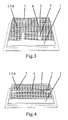
- FIGS. 1 to 4 show the undersides induction dishes according to the invention 1 in the form of rectangular porcelain dishes, which are intended to receive food and keep warm.
- a bottom 2 of the induction harness 1 is enclosed by a circumferential rib 3.
- the bottom 2 has one or more ribs 4 within the fin 2 enclosing the rib 3.
- These ribs 4 are arranged in the embodiments on imaginary lines along and / or transverse to the bottom 2 of the induction harness. As in FIG. 1 to see the ribs 4 can be interrupted.
- the ribs 4 are at a distance from the rib 2 enclosing the bottom 2, namely they are laterally spaced from the enclosing rib 3 and terminate at a distance from the enclosing rib 3.
- the ribs 4 thus have a distance from the edge of the bottom 2 of the induction harness 1 on.
- the bottom 2 of the induction harness 1 has on its underside a coating 5 made of a ferromagnetic material within the enclosing rib 3.
- the ferromagnetic material is referred to below as a ferromagnetic coating 5 or shortly as a coating 5.
- the ferromagnetic coating 5 may, for example, comprise silver oxide.
- the coating 5 is used for inductive heating of the bottom 2 for keeping food in the induction harness 1 with an induction generator, not shown, for example, on a buffet.
- the induction generator for example, similar to a conventional electric cooker see. It has a coil for generating an alternating magnetic field, which induces eddy currents in the ferromagnetic coating 5, which are converted into heat by the electrical resistance of the coating 5.
- the ferromagnetic coating 5 is not arranged over the entire surface of the bottom 2 of the induction harness 1, but divided into fields 6.
- the coating has 5 recesses, which can also be construed as interruptions 8 and extending in the extension of the ribs 4 continuously up to the rib 2 surrounding the bottom 2 and / or as in FIG. 1 to continue until another rib 4 continues.
- the ferromagnetic coating 5 can be divided by interruptions 7 into 6 fields, as in Figures 1 and 2 you can see.
- the interruptions 7 divide the ferromagnetic coating 5 of the bottom 2 of the induction harness 1 into separate fields 6, which are as equal as possible in size and shape.
- the bottom 2 is divided into two equal fields 6, which are half the size of the bottom 2.
- the bottom 2 is divided into four, six and three fields 6, which occupy a corresponding fraction of a surface of the bottom 2.
- induced eddy currents are limited by the division of the coating 5 into 6 fields on correspondingly small areas. This counteracts a locally uneven heating of the bottom 2 and thereby against thermal stresses that can cause the bottom 2 to crack.
- the subdivision of the ferromagnetic coating 5 of the bottom 2 causes a more uniform heat distribution and reduces thermal stresses, the risk of destruction of the induction harness by thermal stresses is reduced.
- the fields 6 of the thermal coating 5 have no constrictions, bottlenecks or the like. On. This prevents a collapse of field lines of the induced eddy currents, a locally stronger heat generation, which would also lead to thermal stresses, is avoided.
- FIG. 5 shows a pitch-shaped inventive induction tableware 1 with a circular, round bottom 2. Circumferentially at the edge, the bottom 2 a enclosing rib 3 on. Within the rib 3 is the bottom with a provided annular ferromagnetic coating 5, outside the enclosing rib 3, an annular ferromagnetic coating 5 is present. Both coatings 5 can be regarded as fields 6, which are interrupted at the enclosing rib 3. The coating 5 within the enclosing rib 3 may be different from the drawing circular.
- All described embodiments of the invention have in common that the field lines generated by an induction generator are interrupted by the interruptions of the ferromagnetic coating 5 and thus can no longer form large-scale eddy currents. As a result, in turn, the coupling of the energy is distributed less and above all evenly over the surface of the bottom 2 of the induction harness 1. The energy flow is specifically disturbed, which advantageously has the consequence that a heat-related damage of the porcelain preferably used for the induction harness 1 no longer occurs.
Landscapes
- Engineering & Computer Science (AREA)
- Food Science & Technology (AREA)
- Manufacturing & Machinery (AREA)
- Cookers (AREA)
Description
- Die vorliegende Erfindung betrifft ein Induktionsgeschirr wie beispielsweise eine Schüssel oder eine Schale zum Warmhalten von Speisen mit den Merkmalen des Oberbegriffs des Anspruchs 1, das insbesondere zum Anbieten warmer Speisen an Buffets im Gastronomiebereich vorgesehen ist.
- Ein Kochgeschirr, wie beispielsweise ein Kochtopf oder eine Pfanne, wird im Allgemeinen aus einer mit Nahrungsmittel verträglichen Legierung hergestellt, beispielsweise aus einem nichtrostenden Stahl oder aus einer Aluminiumlegierung. Wenn das Kochgeschirr durch Induktion erwärmt werden soll, weist sein Boden eine ferromagnetischen Legierung auf. Nahrungsmittelverträgliche Legierungen sind im Allgemeinen nicht magnetisch und können daher wegen ihres allgemein massgeblichen Frequenzbereichs nicht durch Induktion erwärmt werden. Das ferromagnetische Material kann dagegen durch Induktion erwärmt werden und bildet einen Heizbereich für solche Kochgeschirre. Im Nachfolgenden wird zur Beschreibung des Induktionsgeschirrs von einem Behälter gesprochen. Darunter werden alle Gefässe, Platten, Teller, Becher, Töpfe, Pfannen etc, verstanden, die die Eigenschaft aufweisen, mindestens ein Lebensmittel aufzunehmen, zu bearbeiten, zu präsentieren oder warm zu halten.
- Bekannte Induktionsgeschirre aus Metall weisen in ihrem Bodenbereich ein ferromagnetisches Material auf, das dazu dient, ein von einer Spule erzeugtes magnetisches Wechselfeld in Wärme umzusetzen, die an ein Lebensmittel in bzw. auf dem Induktionsgeschirr zu dessen Aufwärmung abgegeben wird.
- Ferner sind z. B. aus der
AT 009 021 U1 - Auch ist es bekannt, dass man ein ferromagnetisches Material als Induktionselement vor einem Glasierungsprozess eines dielektrischen Geschirrs,auf dessen Boden aufbringt, sodass das Induktionselement nach dem Glasierungsprozess einglasiert ist. Dies bringt unter anderem den Vorteil mit sich, dass das Geschirr spülmaschinenfest ist.
- Die bekannten Geschirrteile weisen die Eigenschaft auf, dass ein ferromagentisches Material die gesamte Bodenfläche des Geschirrs abdeckt. Dies bedeutet, dass eine Unterseite, beispielsweise eines Tellers, vollständig mit dem ferromagnetisch Platte bedeckt ist. Auch bei Servierplatten, die überwiegend aus Porzellan bestehen, ist es bekannt, die Unterseite vollständig mit feffomagentischem Material zu beschichten, um beispielsweise an einem Warmhaltebuffet Speisen warm zu halten, wobei die Warmhaltefunktion über Induktion erreicht wird.
- Die Praxis hat jedoch gezeigt, dass entweder durch eine unsachgemässe Einstellung eines Induktionsgebers (Warmhalteofen), der das magnetische Wechselfeld erzeugt, oder bei bestimmten Platten bzw. Servierschüsseln bzw. -formen derart viel Energie von dem Induktionsgeber in das ferromagentische Material eingekoppelt wird, dass das z. B. aus Porzellan bestehende Geschirr zu Bruch gehen kann, d. h., dass es aufgrund von unerwünschten Wärmedehnungen Risse oder Sprünge bekommen kann. Dies bedeutet ferner, dass durch das ferromagnetische Material in den Porzellanbehälter zu viel Energie eingebracht wird, wodurch das Geschirr beschädigt werden kann. Das Geschirr wird unbrauchbar. Es hat sich gezeigt, dass das Risiko eines Springens oder Reissens des Geschirrs beim induktiven Erwärmen mit der Größe der Bodenfläche des Geschirrs steigt.
- Die europäische Patentanmeldung
EP 0 688 526 A1 offenbart ein topfförmiges Gar- und/oder Kochgerät, welches für eine bodenseitige Zuführung von Wärmeenergie durch Wärmeleitung oder elektromagnetische Induktion eingerichtet ist. Ein Boden des Gar- und/oder Kochgeräts ist in Sandwichbauart mit einem austenitische Stahlblech als oberer Schicht, einem gut wärmeleitenden Kern z. B. aus einer Aluminium- oder Kupferlegierung und einer metallischen Platinenabdeckung als unterer Schicht ausgebildet. Die obere Schicht des Bodens, d. h. das austenitische Stahlblech ist als Topf geformt, d. h. einstückig mit einer Umfangswand. Die Platinenabdeckung als untere Schicht des Sandwich-Bodens weist Ausnehmungen auf, in die Füllstücke aus ferromagnetischem Stahlblech eingesetzt sind, um ein induktives Erwärmen zu ermöglichen. - Aufgabe der Erfindung ist es, die Wechselwirkung zwischen dem Induktionsgeber und dem ferromagnetischen Material, das an einem Boden des Geschirrs angeordnet ist, derart zu optimieren, dass eine Beschädigung des Geschirrs vermieden wird.
- Diese Aufgabe wird erfindungsgemäß durch die Merkmale des Anspruchs 1 gelöst. Die vorliegende Erfindung sieht vor, ein ferromagnetisches Material am Boden eines Induktionsgeschirrs durch Unterbrechungen in Felder zu unterteilen, die auf Teilflächen des Bodens begrenzt sind. Elektrische Wirbelströme, die ein magnetisches Wechselfeld eines Induktionsgebers erzeugt, können sich nicht über die Unterbrechungen des ferromagnetischen Materials fortsetzen sondern sind auf die Felder begrenzt. Die elektrischen Wirbelströme werden kleinflächiger als der Boden des Induktionsgeschirrs auf die Felder des ferromagnetischen Materials begrenzt, was eine gleichmässigere Wärmeverteilung auf die Fläche des Bodens des Induktionsgeschirrs bewirkt und ein Reissen oder Springen des Induktionsgeschirrs vermeidet oder jedenfalls das Risiko eines Reissens oder Springens des Induktionsgeschirrs verringert. Die Erfindung ist insbesondere für Induktionsgeschirr mit großem Boden vorgesehen, bei dem die Gefahr von Spannungsrissen groß ist.
- Der Boden des erfindungsgemäßen Induktionsgeschirrs weist mindestens eine Rippe an seiner Unterseite zur Versteifung auf. Das Induktionsgeschirr kann auf dieser Rippe stehen, wenn es auf einer Unterlage abgestellt ist. Die Rippe weist bei Ausgestaltungen der Erfindung Abstand von einem Rand des Bodens auf und endet mit Abstand vom Rand des Bodens. Am Rand des Bodens kann ebenfalls eine insbesondere umlaufende Rippe vorhanden sein. Das ferromagnetische Material des Bodens zur Wärmeerzeugung durch Induktion ist an der mindestens einen Rippe ausgespart und in Verlängerung der mindestens einen Rippe bis zum Rand des Bodens des Induktionsgeschirrs oder bis zu einer weiteren Rippe unterbrochen. Das ferromagnetische Material ist dadurch in Felder unterteilt, die Teilflächen des Bodens abdecken.
- Unter ferromagnetischem Material ist ein Material zu verstehen, in dem ein magnetisches Wechselfeld Wirbelströme induziert, die durch einen elektrischen Widerstand des Materials in Wärme gewandelt werden oder noch allgemeiner ein Material, das ein magnetischen Wechselfeld in Wärme wandelt.
- In der Regel wird die Energie über eine oder mehrere Spulen eines oder mehrerer Induktionsgeber in das ferromagnetische Element eingekoppelt. Diese Spulen sind spiralförmig in einer ebenen Kreisfläche in dem Induktionsgeber angeordnet, der einer herkömmlichen elektrischen Kochplatte ähnlich sehen kann. Dies bedeutet, dass das erzeugte magnetische Wechselfeld vollständig in das zum Warmhalten in vorzugsweise einem sehr geringen Abstand darauf angeordnete ferromagnetische Material des Bodens des Induktionsgeschirrs Material eingekoppelt wird. Die Erfindung vermeidet extrem hohe Temperaturen und insbesondere eine extrem ungleichmäßige Temperaturverteilung dadurch, dass es das ferromagnetische Material in Felder unterteilt. Die Induktion in Feldern, die kleiner als der Boden des Induktionsgeschirrs sind, vermeidet extreme thermisch bedingte Materialspannungen im Induktionsgeschirr, und ein Reissen, Springen oder Zerbrechen.
- Zusätzlich oder anstatt der Unterbrechung in Verlängerung der mindestens einen Rippe kann das ferromagnetische Material auch seitlich der mindestens einen Rippe, also innerhalb ihrer Längserstreckung, bis zum Rand des Bodens des Induktionsgeschirrs oder bis zu einer weiteren Rippe, unterbrochen und dadurch in Felder unterteilt sein.
- Vorzugsweise weisen die Felder, in die das ferromagnetische Material unterteilt ist, eine homogene Fläche auf, d. h. sie sind vorzugsweise rund. Beispielsweise auch oval oder elliptisch, oder eckig ohne Innenecken, beispielsweise quadratisch, rechteckig oder vieleckig. Einschnürungen und Engstellen der Felder des ferromagnetischen Materials, an denen Feldlinien der induzierten elektrischen Wirbelströme zusammengedrängt werden, sind möglichst zu vermeiden. Eine Verdichtung der elektrischen Feldlinien bewirkt eine örtlich erhöhte Wärmeerzeugung, die de Boden des Induktionsgeschirrs ungleichmäßig erwärmt, woraus thermische Spannungen resultieren, durch die das Induktionsgeschirr reissen oder springen kann. Das ist erfindungsgemäß durch eine Formgebung der Felder des ferromagnetischen Materials ohne Einschnürungen und ohne Engstellen zu vermeiden.
- Das ferromagnetische Material ist insbesondere als Schicht auf einer Unterseite des Bodens des Induktionsgeschirrs aufgebracht. Es kann beispielsweise als Folie, durch Pulverbeschichtung oder in sonstiger Weise aufgebracht und ggf. eingebrannt sein.
- Die Erfindung ist insbesondere zum Warmhalten von Speisen an Büffets in der Gastronomie vorgesehen. Als Induktionsgeschirr sieht eine Ausgestaltung der Erfindung deswegen Schalen oder Schüsseln vor. Die Erfindung ist allerdings auch auf Teller, Trinkgefässe und sonstige Geschirr anwendbar.
- Vorzugsweise ist der Boden des Induktionsgeschirrs eckig, insbesondere viereckig, quadratisch oder rechteckig. Diese Bodenformen lassen sich gut in nach Form und Größe zumindest näherungsweise gleiche Felder unterteilen, was die gewünschte gleichmäßige Erwärmung durch Induktion bewirkt.
- Auch Induktionsgeschirr mit rundem Boden eignet sich für die Erfindung. Hier sieht eine Ausgestaltung der Erfindung ein ringförmig insbesondere am oder auch ausserhalb des Randes des Bodens angeordnetes ferromagnetische Material vor, das ferromagnetisches Material am Boden des Induktionsgeschirrs umschliesst. Das ringförmige ferromagnetische Material ist vom umgebenen Material getrennt, es besteht weder elektrisch noch magnetisch leitender Kontakt. Der umgebende Ring ferromagnetischen Materials verbessert die Wärmeerzeugung. Bei Induktionsgeschirr mit eckigem Boden ist diese Ausgestaltung normalerweise nicht erforderlich, allerdings auch nicht ausgeschlossen.
- Insbesondere besteht das erfindungsgemäße Induktionsgeschirr aus einem dielelektrischen Material, vorzugsweise aus Keramik, Porzellan oder Steingut. Die Anwendung der Erfindung ist auch bei Induktionsgeschirr aus Glas, Kunststoff oder Metall möglich. Die Aufzählung ist nicht abschliessend.
- Die erfindungsgemäße Ausbildung und Anordnung des ferromagnetischen Materials am Boden des Induktionsgeschirrs, insbesondere an Buffetschalen bzw. Gastronomieschalen, ist vornehmlich nur zum Warmhalten von Speisen gedacht und nicht zum Kochen.
- Die Erfindung wird nachfolgend anhand eines in der Zeichnung dargestellten Ausführungsbeispiels näher erläutert. Die Figuren zeigen eine Auswahl erfindungsgemäßen Induktionsgeschirrs schräg von unten auf einen Boden des Induktionsgeschirrs gesehen.
-
Figuren 1 bis 4 zeigen die Unterseiten erfindungsgemäßen Induktionsgeschirrs 1 in Form rechteckiger Porzellanschalen, die dazu vorgesehen sind, Speisen aufzunehmen und warmzuhalten. Ein Boden 2 des Induktionsgeschirrs 1 ist von einer umlaufenden Rippe 3 umschlossen. Ausserdem weist der Boden 2 eine oder mehrer Rippen 4 innerhalb der den Boden 2 umschliessenden Rippe 3 auf. Diese Rippen 4 sind in den Ausführungsbeispielen auf gedachten Geraden längs und/oder quer zum Boden 2 des Induktionsgeschirrs angeordnet. Wie inFigur 1 zu sehen können die Rippen 4 unterbrochen sein. Die Rippen 4 weisen Abstand von der den Boden 2 umschliessenden Rippe 3 auf, und zwar weisen sie seitlichen Abstand von der umschliessenden Rippe 3 auf und enden mit Abstand von der umschliessenden Rippe 3. Die Rippen 4 weisen somit Abstand vom Rand des Bodens 2 des Induktionsgeschirrs 1 auf. - Der Boden 2 des Induktionsgeschirrs 1 weist an seiner Unterseite eine Beschichtung 5 aus einem ferromagnetischen Material innerhalb der umschliessenden Rippe 3 auf. Das ferromagnetische Material wird nachfolgend als ferromagnetische Beschichtung 5 oder kurz als Beschichtung 5 bezeichnet. Die ferromagnetische Beschichtung 5 kann beispielsweise Silberoxid aufweisen. Die Beschichtung 5 dient einer induktiven Erwärmung des Bodens 2 zum Warmhalten von Speisen im Induktionsgeschirr 1 mit einem nicht dargestellten Induktionsgeber beispielsweise auf einem Buffet. Der Induktionsgeber kann beispielsweise einer herkömmlichen Elektroherdplatte ähnlich sehen. Er weist eine Spule zur Erzeugung eines magnetischen Wechselfelds auf, das in der ferromagnetischen Beschichtung 5 Wirbelströme induziert, die durch den elektrischen Widerstand der Beschichtung 5 in Wärme umgesetzt werden.
- Die ferromagnetische Beschichtung 5 ist nicht vollflächig auf dem Boden 2 des Induktionsgeschirrs 1 angeordnet, sondern in Felder 6 unterteilt. An den Rippen 4 weist die Beschichtung 5 Aussparungen auf, die auch als Unterbrechungen 8 aufgefasst werden können und die sich in Verlängerung der Rippen 4 durchgehend bis zu der den Boden 2 umschliessenden Rippe 3 und/oder wie in
Figur 1 zu sehen bis zu einer anderen Rippe 4 fortsetzen. Auch quer zu den Rippen 3, also innerhalb ihrer Längserstreckung, kann die ferromagnetische Beschichtung 5 durch Unterbrechungen 7 in Felder 6 unterteilt sein, wie es inFiguren 1 und 2 zu sehen ist. - Die Unterbrechungen 7 unterteilen die ferromagnetische Beschichtung 5 des Bodens 2 des Induktionsgeschirrs 1 in voneinander getrennte Felder 6, die nach Größe und Form möglichst gleich sind. In
Figur 4 ist der Boden 2 in zwei gleiche Felder 6 unterteilt, die halb so groß wie der Boden 2 sind. InFiguren 1 bis 3 ist der Boden 2 in vier, sechs und drei Felder 6 unterteilt, die einen entsprechenden Bruchteil einer Fläche des Bodens 2 einnehmen. In der ferromagnetischen Beschichtung 5 induzierte Wirbelströme sind durch die Unterteilung der Beschichtung 5 in Felder 6 auf entsprechend kleine Flächen beschränkt. Das wirkt einer örtlich ungleichmäßigen Erwärmung des Bodens 2 und dadurch Wärmespannungen entgegen, die den Boden 2 reissen lassen können. Die Unterteilung der ferromagnetischen Beschichtung 5 des Bodens 2 bewirkt eine gleichmäßigere Wärmeverteilung und mindert thermische Spannungen, die Gefahr einer Zerstörung des Induktionsgeschirrs durch thermische Spannungen ist verringert. - Die Felder 6 der thermischen Beschichtung 5 weisen keine Einschnürungen, Engstellen oder dgl. auf. Das verhindert ein Zusammendrängen von Feldlinien der induzierten Wirbelströme, eine stellenweise stärkere Wärmeerzeugung, die ebenfalls zu thermischen Spannungen führen würde, wird vermieden.
-
Figur 5 zeigt ein krugförmiges erfindungsgemäßes Induktionsgeschirr 1 mit einem kreisförmigen, runden Boden 2. Umlaufend am Rand weist der Boden 2 eine umschliessende Rippe 3 auf. Innerhalb der Rippe 3 ist der Boden mit einer kreisförmigen ferromagnetischen Beschichtung 5 versehen, ausserhalb der umschliessenden Rippe 3 ist eine kreisringförmige ferromagnetische Beschichtung 5 vorhanden. Beide Beschichtungen 5 können als Felder 6 aufgefasst werden, die an der umschliessenden Rippe 3 unterbrochen sind. Die Beschichtung 5 innerhalb der umschliessenden Rippe 3 kann abweichend von der Zeichnung kreisringförmig sein. - Allen beschriebenen Ausführungsformen der Erfindung ist gemeinsam, dass die von einem Induktionsgeber erzeugten Feldlinien durch die Unterbrechungen der ferromagnetischen Beschichtung 5 unterbrochen werden und somit keine großflächigen Wirbelströme mehr bilden können. Dadurch wird wiederum die Einkopplung der Energie geringer und vor allem gleichmäßiger über die Fläche des Bodens 2 des Induktionsgeschirrs 1 verteilt. Der Energiefluss wird gezielt gestört, was vorteilhaft zur Folge hat, dass eine wärmebedingte Beschädigung des für das Induktionsgeschirr 1 vorzugsweise verwendeten Porzellans nicht mehr auftritt.
-
- 1
- Induktionsgeschirr
- 2
- Boden
- 3
- Rippe
- 4
- Rippe
- 5
- ferromagnetische Beschichtung
- 6
- Feld
- 7
- Unterbrechung
Claims (10)
- Induktionsgeschirr (1) zum Warmhalten von Speisen, mit einem Boden (2), der ein ferromagnetisches Material (5) aufweist, das Unterbrechungen (7) aufweist und dadurch in Felder (6) unterteilt ist, dadurch gekennzeichnet, dass der Boden (2) mindestens eine Rippe (4) an seiner Unterseite in mindestens einer der Unterbrechungen (7) des ferromagnetischen Materials (5) aufweist.
- Induktionsgeschirr (1) nach Anspruch 1, dadurch gekennzeichnet, dass der Boden (2) mindestens eine Rippe (4) an seiner Unterseite aufweist, die sich nicht an seinem Rand befindet und deren Enden Abstand vom Rand des Bodens (2) aufweisen, und dass das ferromagnetische Material (5) an der mindestens einen Rippe (4) ausgespart und in Verlängerung der mindestens einen Rippe () unterbrochen und dadurch in Felder (6) unterteilt ist.
- Induktionsgeschirr (1) nach Anspruch 1 oder 2, dadurch gekennzeichnet, dass der Boden (2) mindestens eine Rippe (4) an seiner Unterseite aufweist, die sich nicht an seinem Rand befindet und deren Enden Abstand vom Rand des Bodens (2) aufweisen, und dass das ferromagnetische Material (5) innerhalb einer Längserstreckung der mindestens einen Rippe (4) eine Unterbrechung (7) aufweist und dadurch in Felder (6) unterteilt ist, die im Bereich der Längserstreckung der mindestens einen Rippe (4) enden.
- Induktionsgeschirr (1) nach einem der Ansprüche 1 bis 3, dadurch gekennzeichnet, dass die Felder (6) aus dem ferromagnetischen Material (5) keine Engstellen aufweisen.
- Induktionsgeschirr (1) nach einem der Ansprüche 1 bis 4, dadurch gekennzeichnet, dass der Boden (2) eine Beschichtung (5) aus dem ferromagnetischen Material (5) aufweist.
- Induktionsgeschirr (1) nach einem der Ansprüche 1 bis 5, dadurch gekennzeichnet, dass das Induktionsgeschirr (1) ein Teller, ein Trinkgefäss, eine Schale oder eine Schüssel ist.
- Induktionsgeschirr (1) nach einem der Ansprüche 1 bis 6, dadurch gekennzeichnet, dass der Boden (2) des Induktionsgeschirrs (1) eckig, insbesondere viereckig, ist.
- Induktionsgeschirr (1) nach einem der Ansprüche 1 bis 7, dadurch gekennzeichnet, dass der Boden (2) des Induktionsgeschirrs (1) rund ist.
- Induktionsgeschirr (1) nach einem der Ansprüche 1 bis 8, dadurch gekennzeichnet, dass das ferromagnetische Material (5) von einem Rings ferromagnetischen Materials (5) umschlossen ist, das keinen Kontakt mit dem ferromagnetischen Material (5) innerhalb des Rings hat.
- Induktionsgeschirr (1) nach einem der Ansprüche 1 bis 9, dadurch gekennzeichnet, dass das Induktionsgeschirr (1) aus einem dielektrischen Material besteht.
Applications Claiming Priority (2)
| Application Number | Priority Date | Filing Date | Title |
|---|---|---|---|
| DE102009025750 | 2009-05-06 | ||
| PCT/DE2010/000485 WO2010127662A1 (de) | 2009-05-06 | 2010-04-29 | Induktionsgeschirr zum warmhalten von speisen |
Publications (2)
| Publication Number | Publication Date |
|---|---|
| EP2427086A1 EP2427086A1 (de) | 2012-03-14 |
| EP2427086B1 true EP2427086B1 (de) | 2013-01-23 |
Family
ID=42315239
Family Applications (1)
| Application Number | Title | Priority Date | Filing Date |
|---|---|---|---|
| EP10722561A Not-in-force EP2427086B1 (de) | 2009-05-06 | 2010-04-29 | Induktionsgeschirr zum warmhalten von speisen |
Country Status (6)
| Country | Link |
|---|---|
| US (1) | US20120037615A1 (de) |
| EP (1) | EP2427086B1 (de) |
| JP (1) | JP5404917B2 (de) |
| CA (1) | CA2760568C (de) |
| DE (1) | DE112010001916A5 (de) |
| WO (1) | WO2010127662A1 (de) |
Families Citing this family (7)
| Publication number | Priority date | Publication date | Assignee | Title |
|---|---|---|---|---|
| US9486109B2 (en) | 2011-07-14 | 2016-11-08 | Tsi Technologies Llc | Induction heating system employing induction-heated switched-circuit vessels |
| US20130101721A1 (en) * | 2011-10-24 | 2013-04-25 | Rodger D. Crocker | Induction-based heat retentive server |
| US9307346B2 (en) * | 2013-12-25 | 2016-04-05 | R2Z Innovations, Inc. | System and a method for remotely interacting with items in an electrical field affected environment |
| EP3119404B1 (de) * | 2014-03-17 | 2019-07-24 | Global Bioprotect IP Pty Ltd | Antimikrobielle desinfektionszusammensetzungen und deren verwendung |
| DE202022101796U1 (de) | 2022-04-04 | 2023-07-07 | Eric Mäurer | Induktionsfähiges Essgeschirr |
| USD1078364S1 (en) * | 2024-12-07 | 2025-06-10 | Meiyun Wei | Food warming mat |
| USD1104608S1 (en) * | 2024-12-18 | 2025-12-09 | Shenzhen Jiachen Plastic Hardware Electronics Co., Ltd | Warming plate |
Family Cites Families (20)
| Publication number | Priority date | Publication date | Assignee | Title |
|---|---|---|---|---|
| GB1157711A (en) * | 1966-10-24 | 1969-07-09 | Electricity Council | Improvements in or relating to Electrical Cooking apparatus and Utensils for use therewith |
| US3979572A (en) * | 1974-10-29 | 1976-09-07 | Mitsubishi Denki Kabushiki Kaisha | Induction heating apparatus |
| DE2552181A1 (de) * | 1975-11-21 | 1977-06-02 | Licentia Gmbh | Verfahren zum herstellen einer elektrisch leitenden kontaktierungsschicht |
| US4454403A (en) * | 1980-12-01 | 1984-06-12 | Raytheon Company | Microwave heating method and apparatus |
| US5647271A (en) * | 1992-07-06 | 1997-07-15 | Seb | Kitchenware with thermal conducting system |
| FR2693093B1 (fr) * | 1992-07-06 | 1994-09-02 | Seb Sa | Ustensile culinaire à fond thermoconducteur. |
| ES2106585T3 (es) * | 1994-04-15 | 1997-11-01 | Fissler Gmbh | Aparato para hervir y/o cocer, que esta dispuesto para la aplicacion de energia calorifica a traves de su fondo mediante conduccion del calor o mediante induccion electromagnetica. |
| DE4412944A1 (de) * | 1994-04-15 | 1995-10-19 | Vesta Ag & Co Ohg | Topfförmiges Gar- und/oder Kochgerät |
| DE4421904C2 (de) * | 1994-06-24 | 1998-05-28 | Vesta Ag & Co Ohg | Topfförmiges Gar- und/oder Kochgerät |
| US5954984A (en) * | 1996-07-31 | 1999-09-21 | Thermal Solutions Inc. | Heat retentive food servingware with temperature self-regulating phase change core |
| JPH10146278A (ja) * | 1996-11-21 | 1998-06-02 | Matsushita Electric Ind Co Ltd | 電磁誘導加熱調理器 |
| KR20030011933A (ko) * | 2000-06-30 | 2003-02-11 | 다케하라 세이칸 가부시키가이샤 | 조리용 용기 |
| JP2003019068A (ja) * | 2001-07-10 | 2003-01-21 | Sanyo Electric Co Ltd | 誘導加熱用食器 |
| FR2833019B1 (fr) * | 2001-11-30 | 2004-09-10 | Imphy Ugine Precision | Alliage ferromagnetique pour la cuisson par induction |
| JP2005512652A (ja) * | 2001-12-14 | 2005-05-12 | クラッド・メタルズ・エルエルシー | 自己制御式誘導子を備えた食品調理装置または食品暖め装置 |
| TWI275498B (en) * | 2002-12-27 | 2007-03-11 | Duplo Seiko Corp | Sheet-binding device |
| WO2005013784A1 (es) * | 2003-07-28 | 2005-02-17 | Comercial Valira S.A. | Metodo de fabricacion de un util para coccion, medios para su realizacion y utensilio resultante |
| US7906748B2 (en) * | 2004-11-03 | 2011-03-15 | Mamoru Imura | Induction heatable cookware and serving ware, method of making induction heatable items, and coating for making induction heatable items |
| ITBS20060025A1 (it) * | 2006-02-10 | 2007-08-11 | Pentolpress S R L | Contenitore da cucina per piastre ad induzione |
| DE102007025026A1 (de) * | 2007-05-29 | 2008-12-11 | Pco Group Gmbh | Popcornmaschine mit Induktionsheizung |
-
2010
- 2010-04-29 DE DE112010001916T patent/DE112010001916A5/de not_active Withdrawn
- 2010-04-29 EP EP10722561A patent/EP2427086B1/de not_active Not-in-force
- 2010-04-29 US US13/264,646 patent/US20120037615A1/en not_active Abandoned
- 2010-04-29 WO PCT/DE2010/000485 patent/WO2010127662A1/de not_active Ceased
- 2010-04-29 JP JP2012508897A patent/JP5404917B2/ja not_active Expired - Fee Related
- 2010-04-29 CA CA 2760568 patent/CA2760568C/en not_active Expired - Fee Related
Also Published As
| Publication number | Publication date |
|---|---|
| JP2012525873A (ja) | 2012-10-25 |
| US20120037615A1 (en) | 2012-02-16 |
| WO2010127662A1 (de) | 2010-11-11 |
| DE112010001916A5 (de) | 2012-05-24 |
| CA2760568A1 (en) | 2010-11-11 |
| EP2427086A1 (de) | 2012-03-14 |
| CA2760568C (en) | 2015-03-31 |
| JP5404917B2 (ja) | 2014-02-05 |
Similar Documents
| Publication | Publication Date | Title |
|---|---|---|
| EP2427086A1 (de) | Induktionsgeschirr zum warmhalten von speisen | |
| EP0379495B1 (de) | Kochgeschirr | |
| DE10127051C2 (de) | Kochfeld | |
| CH667790A5 (de) | Kochtopf. | |
| EP4042909B1 (de) | Küchenutensil zum aufstellen auf ein induktionskochfeld | |
| DE10120500B4 (de) | Induktionsgrillplatte und damit hergestellter Induktionsgrill | |
| DE602004002154T2 (de) | Kochgerät bei dem der mantel des behälterbodens ein verzierungselement umfasst und dazugehörendes herstellungsverfahren | |
| DE202005002549U1 (de) | Gargutträger | |
| DE102011000278A1 (de) | Induktionsherd | |
| EP0917847A1 (de) | Wok-Pfanne | |
| DE102017104727A1 (de) | Kochgeschirr zur Verwendung mit einem Induktionskochfeld | |
| DE102009019765A1 (de) | Grillvorrichtung für ein Induktionskochfeld | |
| DE4134740C1 (en) | Cooking pot mfr. - comprises applying heat distribution coating of aluminium@ or copper@ on base of deep-drawn stainless steel body, then surface coating by plasma spraying | |
| DE202006005171U1 (de) | GN-Behälter und insbesondere damit ausgerüstetes Kochsystem | |
| DE102006014818A1 (de) | Vorrichtung zum Zubereiten und/oder Warmhalten von Gargut | |
| DE8630655U1 (de) | Doppelwandiges Koch-, Brat- oder Backgefäß | |
| AT525168B1 (de) | Kochgeschirr für ein Induktionskochfeld | |
| DE102020113079B4 (de) | Aufsatz-Platte, vorzugsweise Teppanyaki-Platte, für ein Kochfeld | |
| DE202022101796U1 (de) | Induktionsfähiges Essgeschirr | |
| DE20116711U1 (de) | Induktionsgrillplatte und damit hergestellter Induktionsgrill | |
| EP2463589A1 (de) | Induktionskochfeld mit einer Kochplatte und einem unter der Kochplatte angeordneten Induktor | |
| DE102023204839A1 (de) | Kochfeldzubehörvorrichtung | |
| DE20015128U1 (de) | Kochgeschirr | |
| EP0324061B1 (de) | Kochgeschirr | |
| DE4439654C2 (de) | Friteuse und Verfahren zu deren Betrieb |
Legal Events
| Date | Code | Title | Description |
|---|---|---|---|
| PUAI | Public reference made under article 153(3) epc to a published international application that has entered the european phase |
Free format text: ORIGINAL CODE: 0009012 |
|
| 17P | Request for examination filed |
Effective date: 20110928 |
|
| AK | Designated contracting states |
Kind code of ref document: A1 Designated state(s): AT BE BG CH CY CZ DE DK EE ES FI FR GB GR HR HU IE IS IT LI LT LU LV MC MK MT NL NO PL PT RO SE SI SK SM TR |
|
| DAX | Request for extension of the european patent (deleted) | ||
| GRAP | Despatch of communication of intention to grant a patent |
Free format text: ORIGINAL CODE: EPIDOSNIGR1 |
|
| GRAS | Grant fee paid |
Free format text: ORIGINAL CODE: EPIDOSNIGR3 |
|
| GRAA | (expected) grant |
Free format text: ORIGINAL CODE: 0009210 |
|
| AK | Designated contracting states |
Kind code of ref document: B1 Designated state(s): AT BE BG CH CY CZ DE DK EE ES FI FR GB GR HR HU IE IS IT LI LT LU LV MC MK MT NL NO PL PT RO SE SI SK SM TR |
|
| REG | Reference to a national code |
Ref country code: GB Ref legal event code: FG4D Free format text: NOT ENGLISH |
|
| REG | Reference to a national code |
Ref country code: CH Ref legal event code: EP |
|
| REG | Reference to a national code |
Ref country code: CH Ref legal event code: EP Ref country code: AT Ref legal event code: REF Ref document number: 594502 Country of ref document: AT Kind code of ref document: T Effective date: 20130215 |
|
| REG | Reference to a national code |
Ref country code: IE Ref legal event code: FG4D Free format text: LANGUAGE OF EP DOCUMENT: GERMAN |
|
| REG | Reference to a national code |
Ref country code: DE Ref legal event code: R096 Ref document number: 502010002228 Country of ref document: DE Effective date: 20130328 |
|
| REG | Reference to a national code |
Ref country code: CH Ref legal event code: NV Representative=s name: ABACUS PATENTANWAELTE KLOCKE SPAETH BARTH, CH |
|
| REG | Reference to a national code |
Ref country code: LT Ref legal event code: MG4D |
|
| REG | Reference to a national code |
Ref country code: NL Ref legal event code: VDEP Effective date: 20130123 |
|
| PG25 | Lapsed in a contracting state [announced via postgrant information from national office to epo] |
Ref country code: LT Free format text: LAPSE BECAUSE OF FAILURE TO SUBMIT A TRANSLATION OF THE DESCRIPTION OR TO PAY THE FEE WITHIN THE PRESCRIBED TIME-LIMIT Effective date: 20130123 Ref country code: ES Free format text: LAPSE BECAUSE OF FAILURE TO SUBMIT A TRANSLATION OF THE DESCRIPTION OR TO PAY THE FEE WITHIN THE PRESCRIBED TIME-LIMIT Effective date: 20130504 Ref country code: IS Free format text: LAPSE BECAUSE OF FAILURE TO SUBMIT A TRANSLATION OF THE DESCRIPTION OR TO PAY THE FEE WITHIN THE PRESCRIBED TIME-LIMIT Effective date: 20130523 Ref country code: SE Free format text: LAPSE BECAUSE OF FAILURE TO SUBMIT A TRANSLATION OF THE DESCRIPTION OR TO PAY THE FEE WITHIN THE PRESCRIBED TIME-LIMIT Effective date: 20130123 Ref country code: BG Free format text: LAPSE BECAUSE OF FAILURE TO SUBMIT A TRANSLATION OF THE DESCRIPTION OR TO PAY THE FEE WITHIN THE PRESCRIBED TIME-LIMIT Effective date: 20130423 Ref country code: NO Free format text: LAPSE BECAUSE OF FAILURE TO SUBMIT A TRANSLATION OF THE DESCRIPTION OR TO PAY THE FEE WITHIN THE PRESCRIBED TIME-LIMIT Effective date: 20130423 |
|
| PG25 | Lapsed in a contracting state [announced via postgrant information from national office to epo] |
Ref country code: PT Free format text: LAPSE BECAUSE OF FAILURE TO SUBMIT A TRANSLATION OF THE DESCRIPTION OR TO PAY THE FEE WITHIN THE PRESCRIBED TIME-LIMIT Effective date: 20130523 Ref country code: SI Free format text: LAPSE BECAUSE OF FAILURE TO SUBMIT A TRANSLATION OF THE DESCRIPTION OR TO PAY THE FEE WITHIN THE PRESCRIBED TIME-LIMIT Effective date: 20130123 Ref country code: LV Free format text: LAPSE BECAUSE OF FAILURE TO SUBMIT A TRANSLATION OF THE DESCRIPTION OR TO PAY THE FEE WITHIN THE PRESCRIBED TIME-LIMIT Effective date: 20130123 Ref country code: FI Free format text: LAPSE BECAUSE OF FAILURE TO SUBMIT A TRANSLATION OF THE DESCRIPTION OR TO PAY THE FEE WITHIN THE PRESCRIBED TIME-LIMIT Effective date: 20130123 Ref country code: NL Free format text: LAPSE BECAUSE OF FAILURE TO SUBMIT A TRANSLATION OF THE DESCRIPTION OR TO PAY THE FEE WITHIN THE PRESCRIBED TIME-LIMIT Effective date: 20130123 Ref country code: PL Free format text: LAPSE BECAUSE OF FAILURE TO SUBMIT A TRANSLATION OF THE DESCRIPTION OR TO PAY THE FEE WITHIN THE PRESCRIBED TIME-LIMIT Effective date: 20130123 Ref country code: GR Free format text: LAPSE BECAUSE OF FAILURE TO SUBMIT A TRANSLATION OF THE DESCRIPTION OR TO PAY THE FEE WITHIN THE PRESCRIBED TIME-LIMIT Effective date: 20130424 |
|
| PG25 | Lapsed in a contracting state [announced via postgrant information from national office to epo] |
Ref country code: HR Free format text: LAPSE BECAUSE OF FAILURE TO SUBMIT A TRANSLATION OF THE DESCRIPTION OR TO PAY THE FEE WITHIN THE PRESCRIBED TIME-LIMIT Effective date: 20130123 |
|
| BERE | Be: lapsed |
Owner name: GASTROS A.G. Effective date: 20130430 |
|
| PG25 | Lapsed in a contracting state [announced via postgrant information from national office to epo] |
Ref country code: DK Free format text: LAPSE BECAUSE OF FAILURE TO SUBMIT A TRANSLATION OF THE DESCRIPTION OR TO PAY THE FEE WITHIN THE PRESCRIBED TIME-LIMIT Effective date: 20130123 Ref country code: CZ Free format text: LAPSE BECAUSE OF FAILURE TO SUBMIT A TRANSLATION OF THE DESCRIPTION OR TO PAY THE FEE WITHIN THE PRESCRIBED TIME-LIMIT Effective date: 20130123 Ref country code: EE Free format text: LAPSE BECAUSE OF FAILURE TO SUBMIT A TRANSLATION OF THE DESCRIPTION OR TO PAY THE FEE WITHIN THE PRESCRIBED TIME-LIMIT Effective date: 20130123 Ref country code: SK Free format text: LAPSE BECAUSE OF FAILURE TO SUBMIT A TRANSLATION OF THE DESCRIPTION OR TO PAY THE FEE WITHIN THE PRESCRIBED TIME-LIMIT Effective date: 20130123 Ref country code: RO Free format text: LAPSE BECAUSE OF FAILURE TO SUBMIT A TRANSLATION OF THE DESCRIPTION OR TO PAY THE FEE WITHIN THE PRESCRIBED TIME-LIMIT Effective date: 20130123 |
|
| PG25 | Lapsed in a contracting state [announced via postgrant information from national office to epo] |
Ref country code: CY Free format text: LAPSE BECAUSE OF FAILURE TO SUBMIT A TRANSLATION OF THE DESCRIPTION OR TO PAY THE FEE WITHIN THE PRESCRIBED TIME-LIMIT Effective date: 20130123 Ref country code: MC Free format text: LAPSE BECAUSE OF FAILURE TO SUBMIT A TRANSLATION OF THE DESCRIPTION OR TO PAY THE FEE WITHIN THE PRESCRIBED TIME-LIMIT Effective date: 20130123 |
|
| PLBE | No opposition filed within time limit |
Free format text: ORIGINAL CODE: 0009261 |
|
| STAA | Information on the status of an ep patent application or granted ep patent |
Free format text: STATUS: NO OPPOSITION FILED WITHIN TIME LIMIT |
|
| 26N | No opposition filed |
Effective date: 20131024 |
|
| REG | Reference to a national code |
Ref country code: IE Ref legal event code: MM4A |
|
| PG25 | Lapsed in a contracting state [announced via postgrant information from national office to epo] |
Ref country code: BE Free format text: LAPSE BECAUSE OF NON-PAYMENT OF DUE FEES Effective date: 20130430 |
|
| REG | Reference to a national code |
Ref country code: DE Ref legal event code: R097 Ref document number: 502010002228 Country of ref document: DE Effective date: 20131024 |
|
| PG25 | Lapsed in a contracting state [announced via postgrant information from national office to epo] |
Ref country code: IE Free format text: LAPSE BECAUSE OF NON-PAYMENT OF DUE FEES Effective date: 20130429 |
|
| GBPC | Gb: european patent ceased through non-payment of renewal fee |
Effective date: 20140429 |
|
| PG25 | Lapsed in a contracting state [announced via postgrant information from national office to epo] |
Ref country code: GB Free format text: LAPSE BECAUSE OF NON-PAYMENT OF DUE FEES Effective date: 20140429 |
|
| PG25 | Lapsed in a contracting state [announced via postgrant information from national office to epo] |
Ref country code: MT Free format text: LAPSE BECAUSE OF FAILURE TO SUBMIT A TRANSLATION OF THE DESCRIPTION OR TO PAY THE FEE WITHIN THE PRESCRIBED TIME-LIMIT Effective date: 20130123 |
|
| PG25 | Lapsed in a contracting state [announced via postgrant information from national office to epo] |
Ref country code: SM Free format text: LAPSE BECAUSE OF FAILURE TO SUBMIT A TRANSLATION OF THE DESCRIPTION OR TO PAY THE FEE WITHIN THE PRESCRIBED TIME-LIMIT Effective date: 20130123 |
|
| PG25 | Lapsed in a contracting state [announced via postgrant information from national office to epo] |
Ref country code: TR Free format text: LAPSE BECAUSE OF FAILURE TO SUBMIT A TRANSLATION OF THE DESCRIPTION OR TO PAY THE FEE WITHIN THE PRESCRIBED TIME-LIMIT Effective date: 20130123 |
|
| PG25 | Lapsed in a contracting state [announced via postgrant information from national office to epo] |
Ref country code: MK Free format text: LAPSE BECAUSE OF FAILURE TO SUBMIT A TRANSLATION OF THE DESCRIPTION OR TO PAY THE FEE WITHIN THE PRESCRIBED TIME-LIMIT Effective date: 20130123 Ref country code: HU Free format text: LAPSE BECAUSE OF FAILURE TO SUBMIT A TRANSLATION OF THE DESCRIPTION OR TO PAY THE FEE WITHIN THE PRESCRIBED TIME-LIMIT; INVALID AB INITIO Effective date: 20100429 Ref country code: LU Free format text: LAPSE BECAUSE OF NON-PAYMENT OF DUE FEES Effective date: 20130429 |
|
| REG | Reference to a national code |
Ref country code: FR Ref legal event code: PLFP Year of fee payment: 7 |
|
| REG | Reference to a national code |
Ref country code: AT Ref legal event code: MM01 Ref document number: 594502 Country of ref document: AT Kind code of ref document: T Effective date: 20150429 |
|
| PG25 | Lapsed in a contracting state [announced via postgrant information from national office to epo] |
Ref country code: AT Free format text: LAPSE BECAUSE OF NON-PAYMENT OF DUE FEES Effective date: 20150429 |
|
| REG | Reference to a national code |
Ref country code: FR Ref legal event code: PLFP Year of fee payment: 8 |
|
| REG | Reference to a national code |
Ref country code: FR Ref legal event code: PLFP Year of fee payment: 9 |
|
| PGFP | Annual fee paid to national office [announced via postgrant information from national office to epo] |
Ref country code: CH Payment date: 20190708 Year of fee payment: 10 |
|
| REG | Reference to a national code |
Ref country code: CH Ref legal event code: PL |
|
| PG25 | Lapsed in a contracting state [announced via postgrant information from national office to epo] |
Ref country code: LI Free format text: LAPSE BECAUSE OF NON-PAYMENT OF DUE FEES Effective date: 20200430 Ref country code: CH Free format text: LAPSE BECAUSE OF NON-PAYMENT OF DUE FEES Effective date: 20200430 |
|
| PGFP | Annual fee paid to national office [announced via postgrant information from national office to epo] |
Ref country code: DE Payment date: 20210430 Year of fee payment: 12 Ref country code: IT Payment date: 20210427 Year of fee payment: 12 Ref country code: FR Payment date: 20210423 Year of fee payment: 12 |
|
| REG | Reference to a national code |
Ref country code: DE Ref legal event code: R119 Ref document number: 502010002228 Country of ref document: DE |
|
| PG25 | Lapsed in a contracting state [announced via postgrant information from national office to epo] |
Ref country code: FR Free format text: LAPSE BECAUSE OF NON-PAYMENT OF DUE FEES Effective date: 20220430 Ref country code: DE Free format text: LAPSE BECAUSE OF NON-PAYMENT OF DUE FEES Effective date: 20221103 |
|
| PG25 | Lapsed in a contracting state [announced via postgrant information from national office to epo] |
Ref country code: IT Free format text: LAPSE BECAUSE OF NON-PAYMENT OF DUE FEES Effective date: 20220429 |