EP2426508A2 - Zielerkennungssystem, Erkennungsverfahren und Verarbeitungsprogramm für die erkannte Information - Google Patents
Zielerkennungssystem, Erkennungsverfahren und Verarbeitungsprogramm für die erkannte Information Download PDFInfo
- Publication number
- EP2426508A2 EP2426508A2 EP11180231A EP11180231A EP2426508A2 EP 2426508 A2 EP2426508 A2 EP 2426508A2 EP 11180231 A EP11180231 A EP 11180231A EP 11180231 A EP11180231 A EP 11180231A EP 2426508 A2 EP2426508 A2 EP 2426508A2
- Authority
- EP
- European Patent Office
- Prior art keywords
- target
- transmitters
- receivers
- azimuth
- signal
- Prior art date
- Legal status (The legal status is an assumption and is not a legal conclusion. Google has not performed a legal analysis and makes no representation as to the accuracy of the status listed.)
- Granted
Links
Images


Classifications
-
- G—PHYSICS
- G01—MEASURING; TESTING
- G01S—RADIO DIRECTION-FINDING; RADIO NAVIGATION; DETERMINING DISTANCE OR VELOCITY BY USE OF RADIO WAVES; LOCATING OR PRESENCE-DETECTING BY USE OF THE REFLECTION OR RERADIATION OF RADIO WAVES; ANALOGOUS ARRANGEMENTS USING OTHER WAVES
- G01S15/00—Systems using the reflection or reradiation of acoustic waves, e.g. sonar systems
- G01S15/87—Combinations of sonar systems
- G01S15/876—Combination of several spaced transmitters or receivers of known location for determining the position of a transponder or a reflector
-
- G—PHYSICS
- G01—MEASURING; TESTING
- G01S—RADIO DIRECTION-FINDING; RADIO NAVIGATION; DETERMINING DISTANCE OR VELOCITY BY USE OF RADIO WAVES; LOCATING OR PRESENCE-DETECTING BY USE OF THE REFLECTION OR RERADIATION OF RADIO WAVES; ANALOGOUS ARRANGEMENTS USING OTHER WAVES
- G01S13/00—Systems using the reflection or reradiation of radio waves, e.g. radar systems; Analogous systems using reflection or reradiation of waves whose nature or wavelength is irrelevant or unspecified
- G01S13/02—Systems using reflection of radio waves, e.g. primary radar systems; Analogous systems
- G01S13/06—Systems determining position data of a target
- G01S13/46—Indirect determination of position data
-
- G—PHYSICS
- G01—MEASURING; TESTING
- G01S—RADIO DIRECTION-FINDING; RADIO NAVIGATION; DETERMINING DISTANCE OR VELOCITY BY USE OF RADIO WAVES; LOCATING OR PRESENCE-DETECTING BY USE OF THE REFLECTION OR RERADIATION OF RADIO WAVES; ANALOGOUS ARRANGEMENTS USING OTHER WAVES
- G01S13/00—Systems using the reflection or reradiation of radio waves, e.g. radar systems; Analogous systems using reflection or reradiation of waves whose nature or wavelength is irrelevant or unspecified
- G01S13/87—Combinations of radar systems, e.g. primary radar and secondary radar
- G01S13/878—Combination of several spaced transmitters or receivers of known location for determining the position of a transponder or a reflector
-
- G—PHYSICS
- G01—MEASURING; TESTING
- G01S—RADIO DIRECTION-FINDING; RADIO NAVIGATION; DETERMINING DISTANCE OR VELOCITY BY USE OF RADIO WAVES; LOCATING OR PRESENCE-DETECTING BY USE OF THE REFLECTION OR RERADIATION OF RADIO WAVES; ANALOGOUS ARRANGEMENTS USING OTHER WAVES
- G01S15/00—Systems using the reflection or reradiation of acoustic waves, e.g. sonar systems
- G01S15/02—Systems using the reflection or reradiation of acoustic waves, e.g. sonar systems using reflection of acoustic waves
- G01S15/06—Systems determining the position data of a target
- G01S15/46—Indirect determination of position data
-
- G—PHYSICS
- G01—MEASURING; TESTING
- G01S—RADIO DIRECTION-FINDING; RADIO NAVIGATION; DETERMINING DISTANCE OR VELOCITY BY USE OF RADIO WAVES; LOCATING OR PRESENCE-DETECTING BY USE OF THE REFLECTION OR RERADIATION OF RADIO WAVES; ANALOGOUS ARRANGEMENTS USING OTHER WAVES
- G01S17/00—Systems using the reflection or reradiation of electromagnetic waves other than radio waves, e.g. lidar systems
- G01S17/87—Combinations of systems using electromagnetic waves other than radio waves
-
- G—PHYSICS
- G01—MEASURING; TESTING
- G01S—RADIO DIRECTION-FINDING; RADIO NAVIGATION; DETERMINING DISTANCE OR VELOCITY BY USE OF RADIO WAVES; LOCATING OR PRESENCE-DETECTING BY USE OF THE REFLECTION OR RERADIATION OF RADIO WAVES; ANALOGOUS ARRANGEMENTS USING OTHER WAVES
- G01S7/00—Details of systems according to groups G01S13/00, G01S15/00, G01S17/00
- G01S7/02—Details of systems according to groups G01S13/00, G01S15/00, G01S17/00 of systems according to group G01S13/00
- G01S7/28—Details of pulse systems
- G01S7/285—Receivers
- G01S7/292—Extracting wanted echo-signals
-
- G—PHYSICS
- G01—MEASURING; TESTING
- G01S—RADIO DIRECTION-FINDING; RADIO NAVIGATION; DETERMINING DISTANCE OR VELOCITY BY USE OF RADIO WAVES; LOCATING OR PRESENCE-DETECTING BY USE OF THE REFLECTION OR RERADIATION OF RADIO WAVES; ANALOGOUS ARRANGEMENTS USING OTHER WAVES
- G01S7/00—Details of systems according to groups G01S13/00, G01S15/00, G01S17/00
- G01S7/52—Details of systems according to groups G01S13/00, G01S15/00, G01S17/00 of systems according to group G01S15/00
- G01S7/523—Details of pulse systems
- G01S7/526—Receivers
- G01S7/527—Extracting wanted echo signals
-
- G—PHYSICS
- G01—MEASURING; TESTING
- G01S—RADIO DIRECTION-FINDING; RADIO NAVIGATION; DETERMINING DISTANCE OR VELOCITY BY USE OF RADIO WAVES; LOCATING OR PRESENCE-DETECTING BY USE OF THE REFLECTION OR RERADIATION OF RADIO WAVES; ANALOGOUS ARRANGEMENTS USING OTHER WAVES
- G01S7/00—Details of systems according to groups G01S13/00, G01S15/00, G01S17/00
- G01S7/52—Details of systems according to groups G01S13/00, G01S15/00, G01S17/00 of systems according to group G01S15/00
- G01S7/534—Details of non-pulse systems
- G01S7/536—Extracting wanted echo signals
Definitions
- the present invention relates to a target detection system which transmits a prescribed target detection signal constituted with a radio wave, a sonic wave, or a light wave, and captures a reflected wave from targets to estimate the position of the targets. More specifically, the present invention relates to a target detection system, a detection method, and a detection information processing program, which are capable of detecting targets even in a case where there are a plurality of reflection paths from targets and the intensity of the reflected wave is weak (S/N ratio is low).
- Radars, sonars, lidars, or the like are widely used as the devices for acquiring the position of targets through transmitting waveform information such as a radio wave or a sound wave and measuring the reflected wave from the targets.
- Radars, sonars, lidars, or the like are effective when there is nothing other than the targets that reflects the waves. However, when there is an obstacle or the like in the surroundings or in the middle of the path, those waves may be multiple-reflected and the position of the targets may not be detected precisely or may not even be detected at all. As an example of cases where the influence of the multiple-path is prominent may be a shallow area of the sea. In a shallow area of the sea, a sound wave is multiple-reflected at the seabed and sea surface, so that targets cannot be detected by sonars.
- Patent Document 1 Japanese Unexamined Patent Publication 2008-249532
- This object detection system is structured to bury a plurality of pseudo sound sources along the seabed to detect an object buried in the seabed, to transmit sound waves equivalent to reflected propagation waveforms acquired by each of the pseudo sound sources sequentially from a wave transmitting array on one side, and to receive those by a wave receiving array on the other side provided via the water.
- it is structured to regenerate a case where the positions of each of the pseudo sound sources are changed continuously to transmit transmission signals from the wave transmitting array on one side, and to specify the reflected waves from the buried object according to the extent of sensitivity and the timing of reception of the reflected propagation waveform. It is structured to use the whole part of the wave transmitting array and the receiving array at all times.
- Patent Document 2 Japanese Unexamined Patent Publication 2009-041981 (Patent Document 2)).
- This mobile object detection system is designed to include two radar heads which transmit electromagnetic waves and receive electromagnetic waves reflected at an object at different positions so as to acquire the moving speed and moving direction of the object at the point of detecting the object.
- Non-Patent Document 1 a technique as depicted in " Y. Tsurugaya, T. Kikuchi and K. Mizutani, "Focal Depth Shifting of Phase-Conjugate Wave in Pekeris Waveguide", J. J. A. P., Vol. 47, No. 5, 2008, pp. 4339-4343 " (Non-Patent Document 1) is proposed, i.e., a time reversal method which performs time reversal on a reception signal and transmits the acquired signal.
- FIG. 14 shows a time reversal method of a case with a high S/N ratio (a case where reflection from targets is strong).
- first first transmission of waveform information such as a radio wave or a sonic wave from a signal transmitter/receiver towards a target M (see FIG. 14A) is conducted, and first reception of a first reflected wave signal (including waveform distortion and the like) reflected at the target M is conducted (see FIG. 14B).
- waveform information such as a radio wave or a sonic wave from a signal transmitter/receiver towards a target M
- first reception of a first reflected wave signal including waveform distortion and the like
- a reversal signal is acquired by time-reversing the reflected wave signal received first, a second transmission (re-transmission) of the reversal signal is conducted towards the target M (see FIG. 14C ), and a second reflected wave signal (reflected wave reversal signal) reflected from the target M thereby is received (see FIG. 14D ).
- the second reflected wave signal (reflected wave reversal signal) is in a state where the waveform distortion generated during propagation is offset, so that the peak thereof becomes clear. Thus, the peak can be easily found. Further, the arrival time ⁇ can be found in the case of FIG. 14 , so that it is possible to estimate the distance from the target M and detect the position of the target M.
- Non-Patent Document 1 cannot specify the distance with respect to the targets when the reflection from the targets is weak (in a case of low S/N ratio) so that the position of the targets cannot be specified, even though it is effective in an environment of multiple reflections. This will be described by referring to FIG. 15 .
- FIG. 15 shows a time reversal method used in a case of low S/N ratio.
- a first transmission of a radio wave, an ultrasonic wave, or the like towards the targets from the transmitter/receiver is conducted as in the case of FIG. 14A , and a first reception of a first reflected wave reflected at the target M thereby is conducted.
- a second transmission (re-transmission) of the reversal signal is conducted towards the target M (see FIG. 15C ), and a second reflected wave signal (reflected wave reversal signal) reflected from the target M thereby is received (see FIG. 15D ).
- the second reflected wave (a reflected wave reversal signal) shown in FIG. 15D
- something like a peak can be acquired compared to the case of the reflected waveform information shown in FIG. 15D .
- the position of the target M cannot be detected under such environment where the S/N ratio is low.
- Patent Documents 1 and 2 are in common in respect that both detect the targets.
- An exemplary object of the present invention is to provide a target detection system including a plurality of target-detecting transmitters/receivers constituted with radars, sonars, or lidars, which is capable of effectively estimating the position of a target even when a reflected wave from the target is weak under an environment where multiple reflections are prominent, and to provide a detection method and a detection information processing program.
- the target detection system is characterized to include:
- the target detection method is characterized as a target detection method used for a target detection system which includes at least two target-detecting transmitters/receivers capable of changing setting of detection azimuth placed at a prescribed interval and a main control device including a position calculating module which specifies a position of the target based on azimuth information of the target detected by each of the transmitters/receivers, wherein:
- the detection information processing program is characterized to be non-temporarily stored in a recording medium to be used for a target detection system which includes at least two target-detecting transmitters/receivers capable of changing setting of detection azimuth placed at a prescribed interval and a main control device including a position calculating module which specifies a position of the target based on azimuth information of the target detected by each of the transmitters/receivers, the program causing a computer to execute:
- the detection information processing program is characterized to be non-temporarily stored in a recording medium to be used for achieving operation contents of a main control device of a target detection system which includes at least two target-detecting transmitters/receivers capable of changing setting of detection azimuth placed at a prescribed interval and the main control device including a position calculating module which specifies a position of the target based on azimuth information of the target detected by each of the transmitters/receivers, the program causing a computer to execute:
- the detection information processing program is characterized to be non-temporarily stored in a recording medium to be used or achieving operation contents of transmitters/receivers of a target detection system which includes at least two target-detecting transmitters/receivers capable of changing setting of detection azimuth placed at a prescribed interval and the main control device including a position calculating module which specifies a position of the target based on azimuth information of the target detected by each of the transmitters/receivers, the program causing a computer to execute, for target azimuth information collecting processing executed by each of the transmitters/receivers:
- a target detection system TS includes N-pieces (at least two) of transmitters/receivers 1, 2, 3, ---, N, and a main control device 10 which individually controls overall actions of each of the transmitters/receivers 1, 2, 3, ---, N (written as 1 to N hereinafter).
- Each of the transmitters/receivers 1 to N is constituted with a radar, sonar, or lidar to be used for searching a same target.
- the main control device 10 is constituted by including: a transmitter/receiver arranging module 11 which individually sets positions and attitudes of each of the transmitters/receivers 1 to N and gives instructions to each of the transmitters/receivers 1 to N regarding the setting of the actual layout positions and attitudes of each of the transmitters/receivers 1 to N; a position calculating module 12 which calculates the position of the target M based on information sent from each of the transmitters/receivers 1 to N, i.e., based on the azimuth information of the target M captured by each of the transmitters/receivers 1 to N; and a timing control module (signal output control module) 13 which gives an instruction regarding operation timings of transmission/reception of signals of each of the transmitters/receivers 1 to N.
- a transmitter/receiver arranging module 11 which individually sets positions and attitudes of each of the transmitters/receivers 1 to N and gives instructions to each of the transmitters/receivers 1 to N regarding the setting of
- the position calculating module 12 is provided with an azimuth information superimposing processing function which performs superimposing processing of reception signals according to a plurality of pieces of reception information (or azimuth information) captured by each of the transmitters/receivers 1 to N by transmitting/receiving the transmission signals regarding the target on the basis of the layout positions (coordinate positions) of each of the transmitters/receivers 1 to N. Further, the position calculating module 12 is provided with a target position estimating function which estimates a position (coordinate position) of a high reflection level acquired by executing the reception signal superimposing processing function as the position of the target M.
- the first exemplary embodiment is structured to place a plurality of the same target detection transmitters/receivers each being constituted with a radar, sonar, lidar, or the like at different positions and perform superimposing processing on the information regarding the reflected waves from the target M acquired by each of the transmitters/receivers 1 to N by using the position calculating module 12 as described above.
- the position calculating module 12 it is possible to acquire the reception wave intensity of a higher level than the surrounding noises even when the level of the reception wave from the target M received at a single transmitter/receiver is weak under an environment where the multiple reflections are prominent because of obstacles and the like, since the reception weaves received at the plurality of transmitters/receivers are superimposed. This makes it possible to effectively and promptly estimate and detect the position of the target.
- the first exemplary embodiment may be structured to select two specific transmitters/receivers and to execute control operations for each of the structural modules by the main control device 10 when operating the target detection system TS. Further, it is also possible to employ a structure with which a third transmitter/receiver having the same function as that of the two transmitters/receivers 1, 2 but being placed at a different layout position is selected further, and the main control device 10 executes the control operations for each of the structural modules directed to each of the first to third transmitters/receivers 1, 2, 3.
- Each of the transmitters/receivers 1 to N according to the first exemplary embodiment is all constituted with a transmitter/receiver having a same function. Therefore, the transmitter/receiver I will simply be described hereinafter.
- the transmitter/receiver 1 includes: a transmitting/receiving module 1a constituted with a radar, sonar, or lidar for transmitting/receiving a prescribed signal for detecting a target; a signal reversing module 1b which accumulates waveform information received at the transmitting/receiving module 1a, performs time reversal on the accumulated waveform information at a timing designated by the transmitting/receiving module 1a and transmits it as a transmission time reversal signal to the transmitting/receiving module 1a; a signal integrating module 1c which sections the reception signal received at the transmitting/receiving module 1a by a time range and an azimuth range designated in advance, integrates each of those, and transmits the integrated information to the position calculating module 12; a transmitter/receiver main body 1A which houses and holds each of those modules; and a position/attitude setting control module 1d which specifies information regarding the position and attitude of the
- the transmitting/receiving module 1a is formed with an information collectable radar, sonar, or lidar constituted with a single sensor element or a plurality of sensor elements which receive waves such as a radio wave, a sonic wave, or a light wave.
- This transmitting/receiving module 1a stores in advance waveform information that is time-series fluctuations of a wave such as wavelength, amplitude, phase, and modulation method of a wave to be transmitted such as a radio wave, sonic wave, or a light wave.
- different frequency bands are set for each of the transmitters/receivers in the first exemplary embodiment for discriminating the waveform information among each of the transmitters/receivers 1 to N.
- frequency hopping with which the frequency changes intermittently to have the frequency hopped for each of the transmitters/receivers.
- the transmitting/receiving module 1a of the transmitter/receiver 1 is structured to read out the waveform information stored in advance at the transmission timing, amplifies the amplitude of the read out waveform information with an amplification rate given in advance, and transmits it as a transmission signal towards the target M,.
- This transmission signal is the same as the waveform information shown in FIG. 14A under an environment with a small amount of noise, for example. Meanwhile, this transmission signal is the same as the waveform information shown in FIG. 15A under an environment with a large amount of noise. In this regards, the transmission signals in both environments are the same.
- each of the transmitting/receiving modules 1a to Na of each of the plurality of transmitters/receivers 1 to N in the first exemplary embodiment is structured to operate according to an instruction of the timing control module (signal output control module) 13 of the main control device 10 to specify and transmit/receive a transmission signal regarding waveform information that is different mutually from transmission signals transmitted from other transmitters/receivers as a target detection signal (used frequency bands are different).
- the timing control module signal output control module 13 of the main control device 10 to specify and transmit/receive a transmission signal regarding waveform information that is different mutually from transmission signals transmitted from other transmitters/receivers as a target detection signal (used frequency bands are different).
- the transmitting/receiving module 1a of each of the plurality of transmitters/receivers 1 to N may be structured to operate according to an instruction of the timing control module (signal output control module) 13 of the main control device 10 and to operate at different timings mutually with respect to the other transmitters/receivers 1 to N so as to specify and transmit/receive a transmission signal regarding prescribed waveform information as a target detection signal.
- This provides such an advantage that it becomes possible to specify and transmit/receive the transmission signals regarding the same waveform information transmitted from each of the transmitters/receivers 1 to N as the target detection signals.
- While the first exemplary embodiment is structured in this case to specify and transmit/receive the transmission signal regarding waveform information that is different mutually from transmission signals transmitted from other transmitters/receivers as a target detection signal for the transmission signals transmitted from each of the transmitters/receivers 1 to N, it is also possible to use the same waveform information by shifting the timings of transmissions.
- this transmitting/receiving module 1a after transmitting the transmission signal starts reception after waiting for a specific time given in advance in order to avoid a strong reflection caused due to media such as the air and water in the vicinity of the transmitting/receiving module 1a or caused due to floating matters and the like contained in those media.
- the transmitting/receiving module 1a is structured to receive a reflected wave from the target M and to store it as a reception signal.
- the stored reception signal is the same as the reflected wave shown in FIG. 14B under a fine environment, for example, while it is the same as the reflected wave shown in FIG. 15B under a bad environment where the S/N ratio is low.
- the transmitting/receiving module 1a is structured by including a function which estimates arriving azimuth and time of the direct wave based on the positions and transmission time of the other transmitters/receivers 2, 3, ---, N and stop reception from the corresponding azimuth during that time in order to avoid direct waves transmitted from the transmitting/receiving modules 2a, 3a, ---, Na of the other transmitters/receivers 2, 3, ---, N at the time of reception.
- the transmitting/receiving module 1a is formed with a radar, sonar, lidar, or the like by placing a plurality of sensor elements, those are placed at a half-wavelength interval on a straight line in general.
- the layout there is no limit set in terms of the layout.
- the sensor elements as a plurality of transmitting/receiving modules 1a may be placed in a ring form, placed in a spherical form, or placed in a stereoscopic lattice-like form that is very similar to crystal lattice to be formed with radars, sonars, lidars, or the like.
- Each of those sensor elements being arranged has the same sensitivity characteristic and wavelength characteristic in most of the cases.
- sensor elements with different sensitivity characteristics and wavelength characteristics may be arranged as well.
- the signal reversing module 1b of the transmitter/receiver 1 has a function which accumulates reception information regarding the reception signal acquired by the transmitting/receiving module 1a at the timing designated by the transmitter/receiver 1.
- the transmitting/receiving module 1a requests output of a reversal timing signal to the signal reversing module 1b, when the reversal timing is designated by the timing control module 13 of the main control device 10.
- the signal reversing module 1b has a function which reads out reception waveform information of the reception signal within a designated time range according to a procedure programmed in advance, performs time reversal, and sends out the time-reversed reception signal to the transmitting/receiving module 1a as a re-transmission signal.
- the waveform information accumulated sequentially on a memory in order of time is read out from the latest to the oldest in a reversed manner.
- the transmitting/receiving module 1a has a function which amplifies the time-reversed reception signal supplied from the signal reversing module 1b and re-transmits it as a time reversal transmission signal (re-transmission signal) towards the target M.
- the time reversal transmission signal to be transmitted is of a waveform close to the reflected wave shown in FIG. 14C under a fine environment, for example, while it is of a waveform close to the reflected wave shown in FIG. 15C under a bad environment where the S/N ratio is low.
- the transmitting/receiving module 1a is structured to receive the reflected wave from the target M for the time reversal transmission signal and store it as a reflected time reversal signal.
- the reflected wave from the target M is similar to the reflected wave shown in FIG. 14D under a fine environment, for example, while it is similar to the reflected wave shown in FIG. 15D under a bad environment where the S/N ratio is low.
- the signal integrating module 1c of the transmitter/receiver 1 has a function which sections the reflected time reversal signal received at the transmitting/receiving module 1a by a time range and an azimuth range designated in advance, integrates each of those, calculates the intensity of the wave by each azimuth and each distance, and transmits those to the position calculating module 12 as the waveform intensities.
- the position/attitude control module 1d of the transmitter/receiver 1 acquires the position of the transmitter/receiver 1 from GPS, matching with a topographic map or the like, or a record of actions taken theretofore, and acquires attitude information of the transmitter/receiver 1 from an attitude sensor or a record of actions taken theretofore. Further, the position/attitude control module 1d is structured to store information regarding the position and attitude of the transmitter/receiver 1 and give it to the transmitter/receiver layout module 11.
- the position/attitude control module 1d is structured to move and set the transmitter/receiver 1 itself to the position designated by the transmitter/receiver layout module 11 by a power device equipped in advance.
- the position/attitude control module 1d includes: a position/attitude sensor 1d 01 which monitors the position and attitude of the transmitter/receiver 1 by using a GPS, gyroscope, compass, or the like; and a main body moving power device 1d 02 such as a screw, propeller drive (in a case of underwater), jet blower, rocket blower, or the like (in a case of space) for moving the transmitter/receiver 1 itself to set a difference with respect to the positional information and the attitude information on a three-dimensional coordinates of X-Y-Z in the instruction information to be substantially zero based on the transmitter/receiver information acquired by the position/attitude sensor 1d 01 .
- the position/attitude control module 1d is structured by including a radio or wired external communication module 1d 03 which transmits position/attitude data to the main control device 10 and receives a moving instruction, and a computer (arithmetic operation control unit) 1d 04 which controls each action of the position/attitude sensor 1d 01 , the main body moving power device 1d 02 , and the external communication module 1d 03 .
- the power device may be achieved by such a form that pulls the transmitters/receivers from outside, for example.
- the transmitter/receiver layout module 11 is structured to acquire the positional information and the attitude information of each of the transmitters/receivers 1 to N from the corresponding position/attitude control module 1d and to inform the information of the position and attitude designated in advance regarding the transmitter/receiver 1 or the information regarding the positions and attitudes of each of the transmitters/receivers 1 to N designated from an external instruction device 20 to the corresponding position/attitude control module 1d, 2d, 3d, ---, Nd.
- the contents of the new technique disclosed herein are the contents directed to specification of the azimuth information of the target M in a case where the measurement of the distance is impossible.
- the new technique can be directly applied even to cases where there are three or more of the transmitters/receivers.
- angle ⁇ shows an azimuth angle for transmitting a detection signal on the basis of a segment S.
- the azimuth angle ⁇ is set to be able to transmit signals by sequentially changing the azimuth of signal transmission by reciprocally scanning the directions between 0 degree and 180 degrees on the horizontal plane.
- the horizontal direction located on the upper side of the segment S in FIG. 3A is taken as a target range.
- the transmission signal of the first transmission and the reflected wave thereof come to have a signal waveform equivalent to the content shown in FIG. 14B , for example, when the S/N ratio is high, and come to have a signal waveform equivalent to the content shown in FIG, 15B , for example, when the S/N ratio is low.
- the reflected wave from the target M cannot be discriminated with the signal waveform of the content shown in FIG. 15 that is a case with the low S/N ratio.
- the azimuth at which the target M exists cannot be specified, either.
- the first exemplary embodiment employs a time reversal method, and re-transmits the waveform of the time reversal reflected signal (e.g., FIG. 15C ) that is acquired by reversing the reflected wave (waveform of FIG. 15B ) of the first transmission signal.
- a discriminable reflected signal e.g. a waveform conforming to FIG. 15D
- FIG. 15D a discriminable reflected signal
- the time reversal reflected signal (e.g., the waveform of FIG. 15C ) as a re-transmission signal among a waveform sequence is generated in a state where the peak position of the reflected signal from the target M cannot be specified.
- the transmission timing of the discriminable reflected signal from the target M acquired by the time reversal method cannot be specified. Therefore, the reciprocating time to the target M cannot be calculated, and the distance to the target M cannot be calculated.
- the azimuth at the time of transmitting the time reversal reflected signal as the re-transmission signal is the azimuth at which the target M exists.
- the azimuth information of the target M can be specified as the azimuth of the target M since the azimuth thereof is set at first.
- the first exemplary embodiment utilizes that, and it is characterized to specify the azimuth information of the target M by effectively processing the reflected signals from the target M acquired under an environment with a low S/N ratio by the time reversal method in the manner described above and to detect the existing position of the target M at the unknown distance based thereupon by using a plurality of transmitters/receivers while the distance is being unknown.
- FIG. 3B shows an X-Y coordinate system where the target M exists.
- the transmitter/receiver 1 is placed at the origin on the X-Y coordinate system
- the transmitter/receiver 2 is placed at the coordinate position (x 2 , y 2 ) on the segment S tilted by ⁇ degree from the X-axis.
- L 0 shows the distance between the transmitters/receivers 1 and 2.
- the detection signal is transmitted counterclockwise of FIG. 3B in order of ⁇ 1 , ⁇ 2 , ⁇ 3 , --- from the segment S.
- the detection signal is transmitted clockwise of FIG. 3B in order of ⁇ 1 , ⁇ 2 , ⁇ 3 , --- from the segment S.
- the transmitter/receiver 1 can acquire the reflected wave from the target M at the position of azimuth angle ⁇ 2
- the transmitter/receiver 2 can acquire the reflected wave from the target M at the position of azimuth angle ⁇ 2 .
- a clear reflected wave peak cannot be acquired in a case where each of the reflected waves is a waveform sequence as in FIG. 15B under a bad measurement environment with a low S/N ration of the reflected waves.
- the transmitters/receivers 1, 2 generate and re-transmit the time reversal waves of the respective reflected waves to acquire the reflected waves thereof by the time reversal method of the case of FIG. 3A described above, so that the reflected time reversal signals as shown in FIG. 15D can be acquired even though the distance is unknown. Thereby, a peak value as the reflected wave from the target M can be acquired.
- the time reversal method may be employed to all the reflected waves acquired by transmissions at the azimuth angles ⁇ 1 , ⁇ 2 , ⁇ 3 of the transmitter/receiver 1 and at the azimuth angles ⁇ 1 , ⁇ 2 , ⁇ 3 of the transmitter/receiver 2.
- the position calculating module 12 of the main control device 10 performs superimposing processing on the waveform sequence information of the reflected signal acquired first in each of the transmitters/receivers 1, 2 in the azimuth acquired in the manner described above at which the target M exists (azimuth angle ⁇ 2 of the transmitter/receiver 1, azimuth angle ⁇ 2 of the transmitter/receiver 2), it is possible to acquire a peak value with an amplified intensity that is acquired by superimposing small peak values in a crossing area of the both waveform sequence information.
- the discriminable property with respect to the surrounding noise can be improved, Therefore, when it is displayed as an image, the existing position of the target M at that time can be clearly displayed to the outside.
- the case of generating the re-transmission signal and re-transmitting it to acquire clear reflection information from the target M by the time reversal method has been described.
- employed is a method which detects the peak position on a coordinate by performing superimposing processing on all the reflection information regarding the reflected signals acquired by the first transmission signal on the basis of the positional information of each of the transmitters/receivers 1, 2 without using the time reversal method.
- the target detection system TS includes: at least two target-detecting transmitters/receivers 1, 2 capable of setting the azimuth of the detection direction of the target M, which are disposed respectively at different placing positions; and the main control device 10 including the position calculating module 12 which specifies the position of the target M based on the reflection information regarding the azimuth of the target M proved by each of the transmitters/receivers 1,2.
- the position calculating module 12 is provided with a function (a target position estimating function) which specifies the position of the target M by performing superimposing processing of the information regarding the azimuth of the target M acquired by the two transmitters/receivers 1, 2 on the basis of the positional information of each of the transmitters/receivers 1, 2 (execution of azimuth information superimposing processing).
- a function a target position estimating function
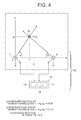
- FIG. 4 is an explanatory chart showing the basic contents of that case.
- an X-Y coordinate system is used as the position coordinate of each of the two transmitters/receivers 1 and 2.
- the coordinate position (X 1 Y 1 ) of the transmitter/receiver 1 is set at the origin O (0, 0)
- the coordinate position (X 2 , Y 2 ) of the transmitter/receiver 2 is set at the coordinate (L, 0) on the X-axis
- the distance between the transmitter/receiver 1 and the transmitter/receiver 2 is set as L.
- the detection area of the target M is assumed in advance, so that the first quadrant of the X-Y coordinate is also assumed as the detection area in this case.
- a depression angle incidence angle towards the Z-axis direction (not shown: direction orthogonal to the paper face) with respect to the X-Y plane
- the azimuth angle (horizontal angle) ⁇ is set while sequentially being switched on the X-Y plane (by each of a plurality of azimuths sectioned in advance) counterclockwise from the X-axis side towards the Y-axis side with respect to the origin O.
- the transmitting/receiving module 1a see FIG. 1 ) of the transmitter/receiver 1 transmits/receives the detection signal.
- the setting range of the depression angle does not necessarily have to be strict considering the directivity of the ultrasonic waves (e.g., about three directions of the upper, middle, lower directions: the exemplary embodiment can correspond to all directions).
- the method of time reversal shown in FIG. 15 is employed to transmit/receive the first transmission/reception signal (see FIG. 15A ) by each section for all the azimuths of the first quadrant and the reception data (see FIG. 15B ) acquired as a result is stored in the transmitting/receiving module 1a and transmitted to the position calculating module 12 of the main control device 10 via the signal integrating module 1c (see FIG. 1 ).
- FIG. 15B it is impossible to clearly discriminate the peak from the noise because of the low S/N ratio, even though there is observed a peak of a signal seemed to be of the reflected wave from the target M. Thus, it cannot be surely confirmed as the reflected wave from the target M.
- the transmitting/receiving module 1a of the transmitter/receiver 1 stores the received/stored first reception data (reception signal containing the peak signal seemed to be of the reflected wave) to the signal reversing module 1b for generating a time reversal signal, gives an instruction to the signal reversing module 1b to generate a time reversal transmission signal for re-transmission based on the instruction from the timing control module (signal output control module) 13 or continuously to the receiving action of the first transmission/reception signal, and re-transmits the time reversal transmission signal (see FIG. 15C ) generated thereby towards the detection area of the target M.
- FIG. 15D shows a reflected time reversal signal of a case where the re-transmitted time reversal transmission signal is reflected from the target detection area.
- a relatively clear peak signal that is not observed in FIG. 15B is captured.
- This captured peak signal becomes the azimuth confirmation data for the same azimuth angle (horizontal angle) ⁇ (see FIG. 4 ).
- the captured reflected time reversal signal of FIG. 15C is stored as the azimuth confirmed data of the same azimuth angle (horizontal angle) ⁇ to the signal integrating module 1c along with the reception data from the corresponding first target detection area, and transmitted to the position calculating module 12 along with the coordinate information (0, 0) of the transmitter/receiver 1.
- a depression angle (incidence angle towards the Z-axis direction (not shown: direction orthogonal to the paper face) with respect to the X-Y plane) at the time of transmitting/receiving signals is set to a prescribed value.
- the rotating axis line is switched sequentially while being rotated on the X-Y plane (by each of a plurality of azimuths sectioned in advance) clockwise from the X-axis side towards the Y-axis side with respect to the coordinate position (L, 0).
- the transmitting/receiving module 2a transmits/receives the detection signal.
- the method of time reversal shown in FIG. 15 is employed to transmit receive the first transmission signal (see FIG. 15A ) by each section for all the azimuths of the first quadrant on the X-Y plane and the reception data (see FIG. 15B ) acquired as a result is stored in the transmitting/receiving module 2a and transmitted to the position calculating module 12 of the main control device 10 via the signal integrating module 2c.
- the transmitter/receiver 1 as evident from FIG. 15B ), it cannot be surely confirmed as the reflected wave from the target M even though there is observed a peak of a signal seemed to be of the reflected wave from the target M.
- the transmitting/receiving module 2a of the transmitter/receiver 2 stores the received/stored first reception data (reception signal containing the peak signal seemed to be of the reflected wave) to the signal reversing module 2b for generating a time reversal signal, gives an instruction to the signal reversing module 2b to generate a time reversal transmission signal for re-transmission based on the instruction from the timing control module (signal output control module) 13 or continuously to the receiving action of the first transmission/reception signal, and re-transmits the time reversal transmission signal (see FIG. 15C , for example) generated thereby towards the detection area of the target M.
- a reflected signal almost equivalent to that shown in FIG. 15D can be acquired.
- a relatively clear peak signal that is not observed in FIG. 15C is captured. This captured peak signal becomes the azimuth confirmation data for the same azimuth angle (horizontal angle) ⁇ (see FIG. 4 ).
- the captured reflected time reversal signal of FIG. 15D is stored as the azimuth confirmed data of the same azimuth angle (horizontal angle) ⁇ to the signal integrating module 2c along with the reception data from the corresponding first target detection area, and transmitted to the position calculating module 12.
- the transmitters/receivers 1 and 2 have: a time reversal signal transmitting/receiving function which performs time reversal on the reflected signals from the target detection area (first quadrant) by each of the transmitters/receivers 1, 2 by the time reversal method, and transmits time reversal signals of the reflected signals towards the target detection area as the target detection signals from the respective directions at the same azimuth angle same as the case of the prior reflected signal; and an azimuth confirmation information extracting function which confirms that the azimuth of the case where the reflected signal of the transmitted time reversal signal from the target M is acquired as the azimuth at which the target M exists.
- FIG. 4 shows an example of the specific exemplary embodiment of the two functions.
- the position calculating module 12 of the main control device 10 performs superimposing processing on the azimuth information transmitted from the transmitters/receivers 1, 2 under the setting condition shown in FIG. 4 in the manner described above based on the positional information (coordinate information) of the transmitters/receivers 1, 2 (execution of the azimuth information superimposing processing function).
- the estimated coordinate position of the target M is calculated by performing a prescribed arithmetic operation (the sine theorem of trigonometry, etc.) based on the coordinate positional information (0, 0) (L, 0) of the transmitters/receivers 1, 2 and the azimuth angles ⁇ , ⁇ , and the position of the target M within the crossing area is calculated (execution of the target position estimating function).
- the third transmitter/receiver 3 is placed at the coordinate position (x 3 , y 3 ) in the 45-degree direction of the first quadrant of the coordinate axes on the X-Y plane disclosed in FIG. 4 .
- the third transmitter/receiver 3 used in the first exemplary embodiment is a transmitter/receiver having the same functions as those of the transmitters/receivers 1, 2 described above.
- each of the transmitters/receivers 1 to 3 uses the time reversal method that is the same as the case of FIG. 4 described above.
- each of the transmitters/receivers 1 to 3 can specify the azimuth of the target M with high accuracy.
- FIG. 6 shows another example of a case where three sonars are placed in the same area of the sea to detect the target M.
- sonars 1S and 2S as the transmitters/receivers are loaded on a segment S at a tilt angle ⁇ passing through the origin of the X-Y coordinate system, and it is a case where the target M comes on the straight line that connects each of the sonars S 1 and S2 mutually.
- Each of the sonars 1S and 2S can extract the azimuth at which the target M exists. However, even when the superimposing processing of the reception signals is executed, the distance is unknown as described above under a bad environment. Thus, it is not possible to estimate the existing position of the target M.
- the sonar 3S can clearly extract the azimuth of the target M by the time reversal method.
- the existing position of the target M can be captured clearly.
- FIG. 7 shows an example of this case.
- FIG. 7 illustrates a case where the transmitters/receivers 1, 2 are placed with a distance L provided therebetween on the X-axis of the X-Y-Z coordinate system as in the case of FIG. 4 and the target M is located on the upper side of the X-Y plane in FIG. 4 .
- the coordinate position of the target M is defined as (x, y, z). Further, it is so defined that the depression angle (incidence angle) of the transmitter/receiver 1 when detecting the target M is ⁇ 2 , and the azimuth when switching the facing direction of the horizontal direction is ( ⁇ 1 . It is also so defined that the depression angle (incidence angle) of the other transmitter/receiver 2 when detecting the target M is ⁇ 2, and the azimuth when switching the facing direction of the horizontal direction is ⁇ 1 .
- the depression angles (incidence angles) ⁇ 2 , ⁇ 2 of the transmitters/receivers 1, 2 are set to appropriate values.
- the azimuths (incidence angles) ⁇ 1 , ⁇ 1 , of the transmitters/receivers 1, 2 are rotated by each of the azimuth degrees sectioned in the direction away from the X-axis (e.g., by every 5 degrees) simultaneously or respectively in a sequential manner, and the target M is detected by transmitting/receiving a detection signal towards the upward oblique direction for each time.
- each of the azimuths (incidence angles) ⁇ 1 , ⁇ 1 becomes 90 degrees
- the depression angles (incidence angles) ( ⁇ 2 , ⁇ 2 are then set to other degrees.
- the azimuths (incidence angles) ( ⁇ 1 , ⁇ 1 of the transmitters/receivers 1, 2 are both rotated by each of the azimuth degrees sectioned in the opposite directions of the earlier directions simultaneously or respectively in a sequential manner, and the target M is detected by transmitting/receiving a detection signal towards the upward oblique direction for each time.
- the reflected signals received at each of the transmitters/receivers 1, 2 are stored by each of the transmitters/receivers 1, 2 as reception signals, and time reversal signals of the reception signals are generated simultaneously by the time reversal method to be re-transmitted towards the detection area of the target M to confirm the existence of the target M in the same manner as the case of FIG. 4 .
- the depression angles (incidence angles) ⁇ 2 , ⁇ 2 and the azimuth angles (incidence angles) ⁇ 1 , ⁇ 1 are checked by each of the transmitters/receivers 1, 2, and the waveform information of the reflected reception signals acquired at the time of setting the depression angles (incidence angles) ( ⁇ 2 , ⁇ 2 and the azimuth angles (incidence angles) ⁇ 1 , ⁇ 1 is transmitted to the position calculating module 12 of the main control device 10 along with the angle information for each of the tratismitters/receivers 1,2.
- the position calculating module 12 performs superimposing processing on the transmitted angle information of the target M and the waveform information of the reception signals on all the areas where the azimuth angles (incidence angles) ⁇ 1 , ⁇ 1 change for each of the depression angles (incidence angles) ⁇ 2 , ⁇ 2 .
- the existing position of the target M i.e., the three-dimensional coordinate position (x, y, z) is specified in the same manner as the case of FIG. 4 .
- the reflection intensity containing the noise thereof may be projection-processed on a plane of the X-Y coordinate in accordance with the azimuth angles ⁇ 1 , ⁇ 1 and projection-processed on a plane of the X-Y coordinate in accordance with the depression angles (incidence angles) ⁇ 2 , ⁇ 2.
- the superimposing processing may be performed to specify the current position of the target M, i.e., the three-dimensional coordinate position (x, y, z).
- the third transmitter/receiver 3 is placed at a coordinate position (X 3 , Y 3 , Z 3 ) close to the Y-axis in the first quadrant of the coordinate axes on the X-Y plane disclosed in FIG. 7 .
- the third transmitter/receiver 3, used in the first exemplary embodiment is a transmitter/receiver having the same functions as those of the tratismitters/receivers 1, 2 described above. Further, for extracting the azimuth of the target M, each of the transmitters/receivers 1 to 3 uses the time reversal method that is the same as the case of FIG. 4 described above. Thus, each of all the transmitters/receivers 1 to 3 can specify the azimuth of the target M with high accuracy.
- the reflected reception signals of each of the transmitters/receivers 1 to 3 are superimposed at the position on the coordinate corresponding to the target M without being shifted from each other.
- the signals received at each of the transmitters/receivers 1 to 3 are of a low S/N ratio, the peak value can be easily recognized compared to the signals of the surrounding noise. Therefore, it is excellent in terms of practicality.
- the main control device 10 includes the transmitter/receiver layout device 11, the position calculating module 12, and the timing control module (output waveform control module) 13.
- the position control module 12 is structured to receive the waveform intensity from the signal integrating module 1c of the transmitter/receiver 1 and add (superimpose) it with the waveform intensities from the other transmitters/receivers 2, 3, ---, N on the same coordinate for each coordinate, and also structured to transmit the coordinate information as a coordinate candidate to the timing control module (output waveform module) 13 and the external display device 30 as well as the storage device 40 by considering that it is highly possible that the target M exists at that coordinate at which the waveform intensity becomes greater than the threshold value that is given by the waveform intensity given in advance.
- the timing control module (signal output control module) 13 has a function which calculates the optimum transmission timing of the transmission waveform information of the transmitter/receiver 1 as the transmission timing from each piece of information regarding the position of the transmitter/receiver 1 acquired from the transmitter/receiver layout module 11, the candidate coordinate acquired from the position calculating module 12, the detection range given in advance or the detection range designated from outside successively, and the previous transmission time
- the timing control module (signal output control module) 13 has a function which calculates the optimum timing for reversing the waveform as the reversal timing from each piece of information regarding the position of the transmitter/receiver 1 acquired from the transmitter/receiver layout module 11, the candidate coordinate acquired from the position calculating module 12, the detection range given in advance or the detection range designated by the external designating device 20 successively, and the previous transmission time. Further, the timing control module 13 has a function which informs the transmission timing and the reversal timing to the transmitting/receiving module 1a of the transmitter/receiver 1.
- each of the other transmitters/receivers 2 to N are structured by including transmitting/receiving modules 2a, 3a, ---, Na, signal reversing modules 2b, 3b, ---, Nb, signal integrating modules 2c, 3c, ---, Nc, and position/attitude control modules 2d, 3d, ---, Nd as in the case of the transmitter/receiver 1 as shown in FIG. 1 .
- Each of those other transmitters/receivers 2 to N is structured to be able to transmit/receive signals to the signal transmitter/receiver layout module 11, the position calculating module 12, and the timing control module 13 of the main control device 10 as in the case of the transmitter/receiver 1.
- the transmitter/receiver layout module 11 of the main control device 10 also has a function which acquires positional information and attitude information of each of the transmitters/receivers 2 to N from the position/attitude control modules 2d, 3d, ---, Nd of each of the transmitters/receivers 2 to N, and informs the positional information as well as the attitude information designated in advance regarding each of the transmitters/receivers 2 to N or information regarding the position and attitude of each of the transmitters/receivers 2 to N designated from the external instruction device 20 to the respective corresponding position/attitude control modules 2d, 3d, ---, Nd.
- the other position/attitude control modules 2d, 3d, ---, Nd of each of the transmitters/receivers 2 to N have functions which acquire each attitude information of corresponding each of the transmitters/receivers 2 to N, store each information regarding the positions and attitudes of the transmitters/receivers 2 to N, transmit those to the transmitter/receiver layout module 11, and move main body moving power devices 2d 02 , 3d 02 , Nd 02 provided to the position/attitude control modules 2d, 3d, ---, Nd to individually control to move each of the transmitters/receivers 2 to N.
- the position control module 12 of the main control device 10 is structured to receive the waveform intensity from the signal integrating modules 2c, 3c, ---, Nc of each of the transmitters/receivers 2, 3, ---, N and add (superimpose) the waveform intensities for each coordinate, and also structured to transmit the coordinate information as a coordinate candidate to the timing control module (output waveform module) 13 and the external display device 30 as well as the storage device 40 indicating that it is highly possible that the target M exists at that coordinate which becomes greater than the threshold value that is given by the waveform intensity given in advance.
- the timing control module (signal output control module) 13 has a function which calculates the optimum transmission timing of the transmission waveform information of the transmitter/receivers 2 to N as the transmission timing from each piece of information regarding the position of the transmitter/receiver 1 acquired from the transmitter/receiver layout module 11, the candidate coordinate acquired from the position calculating module 12, the detection range given in advance or the detection range designated from outside successively.
- the timing control module (signal output control module) 13 has a function which calculates the optimum timing for reversing the waveform as the reversal timing from the positional information of each of the transmitters/receivers 2 to N acquired from the transmitter/receiver layout module 11, the candidate coordinate information acquired from the position calculating module 12, the information regarding the detection range given in advance or the detection range designated by the external designating device 20 successively, and the previous transmission time information.
- timing control module 13 is structured to inform the transmission timing and the reversal timing to the transmitting/receiving modules 2a, 3a, ---, Na of each the transmitters/receivers 2 to N.
- the position calculating module 12, the signal reversing module 1b, and the signal integrating module 1c are structured with various kinds of devices capable of performing digital signal processing.
- Each of these modules 12, 1b, and 1c may be a board computer constituted with DSP, mass-storage subsidiary memory device, a mass-storage memory, or the like or may be a typical personal computer or a work station.
- the transmitter/receiver layout module 11 and the timing control module 13 may be formed by having the computers described above as the base.
- the transmitter/receiver layout module 11 includes a wired or radio communication device (communication module) for giving an instruction to move each of the transmitters/receivers 1, 2, 3, ---, N.
- the timing control module 13 also includes a wired or radio communication device (communication module) for giving an instruction regarding the timing of transmission and signal reversal to each of the transmitters/receivers 1 to N.
- the external instruction device 20, display device 30, and storage device 40 may be structured to include different computers from each other as the operation control modules. Alternatively, each of those devices 20, 30, and 40 as a whole may be integrated and controlled to be operated by a single computer, Further, the external instruction device 20, display device 30, storage device 40 and the target detection system S corresponding thereto are structured to be able to exchange data mutually via the wired or radio communication module.
- the communication module used in each of the modules and devices it is possible to use such type using radio waves, sonic waves, light, infrared rays, or the like.
- the transmitter/receiver layout module 11 of the main control device 10 specifies at least two transmitters/receivers 1, 2 from a plurality of transmitters/receivers 1 to N provided for detecting a target, and gives an instruction to each of the transmitters/receivers 1, 2 to set the positions and attitudes thereof towards the target detection direction ( FIG. 9 : step S101).
- each of the transmitters/receivers 1, 2 operates the main body moving power unit 1d 02 provided in advance to set the positions and attitudes of each of the transmitters/receivers 1, 2 in accordance with the instruction contents, and transmits the information regarding the set positions and attitudes (transmitter/receiver information) to the main control device 10 thereafter ( FIG. 9 : step S102).
- the main control device 10 collects it as the transmitter/receiver information by the position calculating module 12 and stores it to the storage device 40 for calculating the target ( FIG. 9 : step S103).
- the timing control module (output waveform control module) 13 of the main control device 10 After collecting the transmitter/receiver information by the position calculating module 12, the timing control module (output waveform control module) 13 of the main control device 10 gives an instruction to each of the transmitters/receivers 1, 2 to generate transmission signals based on either the different waveform information or the same waveform information, and sets the transmission timings of the generated signals at the same time ( FIG. 9 : step S104).
- each of the transmitters/receivers 1 and 2 specified according to the instruction of the timing control module (output waveform control module) 13 generates the transmission signals ( FIG. 9 : step S105).
- reflection signals acquired by transmitting/receiving the generated transmission signals from the transmitters/receivers 1, 2 towards the target M are stored.
- the signal reversing modules 1b, 2b also store those and, thereafter, when there is a request from the transmitting/receiving modules 1a, 2a, generate the respective time reversal signals and transmit those to the transmitting/receiving modules 1a, 2a as the transmission signals ( FIG. 9 : step S106, specification of transmission signal).
- the transmitting/receiving modules 1a, 2a individually transmit/receive re-transmission signals constituted with the time reversal signals towards the target M, and store the acquired reflected time reversal signals to the corresponding transmitters/receivers 1, 2 as the signals for checking the azimuth ( FIG. 9 : step S107).
- Each of the signal integrating modules 1c, 2c integrates the stored reflected time reversal signals of each of the transmitters/receivers 1, 2 by sectioning those by the time range and the azimuth range, and the position calculating module 12 fetches the integrated reflected time reversal signals and performs superimposing processing on a same coordinate ( FIG. 9 : step S108).
- the position calculating module 12 estimates and calculates the coordinate position of a high reflection level on the coordinate acquired by the superimposing processing as the position of the target M ( FIG. 9 : step S109).
- a dotted-line frame of A shows the operations of the transmitter/receiver 1a of the transmitter/receiver 1
- a dotted-line frame of B shows the operations of the signal integrating module 1c.
- the transmitting/receiving module 1a stores in advance the waveform information regarding radio waves, sonic waves, light waves, or the like, which is time-series fluctuation of waves such as the wavelength, amplitude, phase, and modulation method of the waves to be transmitted ( FIG. 10 : step S201).
- the transmitting/receiving module 1a waits for an instruction of the optimum transmission timing for the transmitter/receiver 1 to transmit the transmission signal regarding the transmission waveform information from the timing control module (output waveform control module) 13 ( FIG. 10 : step S202).
- the transmitting/receiving module 1a of the transmitter/receiver 1 Upon inputting the transmission timing designated from the timing control module (output waveform control module) 13, the transmitting/receiving module 1a of the transmitter/receiver 1 reads out the waveform information stored in advance in step S202, generates a transmission signal by performing amplification with an amplifying rate designated in advance by the transmitter/receiver 1 according to the waveform information, and transmits the transmission signal towards the target M ( FIG. 10 : steps S203, S204).
- This transmission signal is the same as the transmission waveform shown in FIG. 15A, for example.
- the transmitting/receiving module 1a After transmitting the transmission signal and time t given in advance has passed ( FIG. 10 : step S205) the transmitting/receiving module 1a gives an instruction to the signal reversing module 1b to accumulate the reception signals and starts reception of signals to receive the reflected waves of the transmission signals from the target M ( FIG. 10 : step S206) in order to avoid strong reflection from the media such as the air and water very close to the transmitting/receiving module 1a or from floating matters contained in the media.
- the signal reversing module 1b accumulates the waveform information after the transmitting/receiving module 1a start the reception as the reception signals ( FIG. 10 : step S207).
- This reception signal is the same as the reception waveform information shown in FIG. 15B, for example.
- the transmitting/receiving module 1a waits for an input of instruction information regarding the reversing timing and time range for time reversal from the timing control module 13 ( FIG. 10 : step S208). Then, when receiving the instruction information regarding the reversal timing, the transmitting/receiving module 1a gives an instruction to the signal reversing module 1b to perform time reversal within the time range designated by the timing control module 13 regarding the reception waveform information accumulated theretofore ( FIG. 10 : step S209).
- the signal reversing module 1b performs time reversal on the signal within the time range designated by the transmitting/receiving module 1a at the timing designated by the transmitting/receiving module 1a, and gives the reversed signal to the transmitting/receiving module 1a for re-transmission.
- the transmitting/receiving module 1a receives the time-reversed re-transmission signal from the signal reversing module 1b ( FIG. 10 : step S210).
- the transmitting/receiving module 1a generates a time reversal transmission signal (re-transmission signal) for transmission by amplifying the amplitude of the transmission signal reversed by the signal reversing module 1b at the reversal timing with the amplifying rate given in advance ( FIG. 10 : step S211).
- the transmitting/receiving module 1a transmits the time reversal transmission signal (re-transmission signal) towards the target M at the reversal timing designated by the timing control module 13 ( FIG. 10 : step S212).
- This time reversal transmission signal is the same as the time reversal waveform signal shown in FIG. 15C, for example.
- step S205 after transmitting the time reversal transmission signal and time t given in advance has passed ( FIG. 10 : step S213), the transmitting/receiving module 1a receives a reflected signal for the time reversal transmission signal at the signal reversing module 1b from the target M and gives it to the signal accumulating module 1c as a time reversal reflected signal ( FIG. 10 : step S214) in order to avoid strong reflection from the media such as the air and water very close to the transmitting/receiving module 1a or from floating matters contained in the media.
- This time reversal transmission signal is the same as the reception waveform information shown in FIG. 15D, for example.
- the signal integrating module 1c receives the time reversal reflected signals from the transmitting/receiving module 1a, integrates the signals by the time range and azimuth range designated in advance to acquire the intensity distribution of the time reversal reflected signals by each time and azimuth, i.e., by each distance and azimuth, as the waveform intensity information, and transmits those to the position calculating module 12 at the prescribed timing ( FIG. 10 : step S215).
- the S/N ratio of the reflection from the target M can be improved for each azimuth through expanding the time range to integrate the signals, i,e., through decreasing the distance resolution. Further, regarding the signal integrating module 1c, it is also possible to acquire the waveform information by shortening the time, i.e., by decreasing the distance resolution, and to separately integrate the signals in the distance direction for each azimuth.
- the signal integrating module 1c transmits the waveform intensity to the position calculating module 12 of the main control device 10 ( FIG. 10 : step S216).
- the other transmitter/receiver 2 executes the same operations.
- the position/attitude control module 1d corresponds to step S102 of the basic operations shown in FIG. 9 described above.
- the position/attitude control module 1d specifies the positional information of the transmitter/receiver 1 from GAPS, matching with a topographic map or the like, or a record of actions taken theretofore, and specifies attitude information of the transmitter/receiver 1 from an attitude sensor or a record of actions taken theretofore ( FIG. 11 : step S221). Further, the position/attitude control module 1d gives the values of the position and attitude of the transmitter/receiver 11 to the transmitter/receiver layout module 11 ( FIG. 11 : step S222).
- the position/attitude control module 1d moves the transmitter/receiver 1 to the position designated by the transmitter/receiver layout module 11 by a power device such as a screw, propeller, jet blower, rocket blower, or the like to complete the setting of the position and attitude of the transmitter/receiver 1 thereby ( FIG. 11 : step S223).
- the other transmitter/receiver 2 executes the same operations.
- the transmitter/receiver layout module 11 first acquires the information regarding the positions and attitudes of each of the transmitters/receivers 1, 2 from each of the position/attitude control modules 1d, 2d of the transmitters/receivers 1, 2 and, further, informs the setting information regarding the positions and attitudes designated in advance regarding each of the transmitters/receivers 1, 2 or setting information regarding the positions and attitudes of each of the transmitters/receivers 1, 2 designated by the external instruction device 20. This is the same when specifying another transmitter/receiver 3N.
- the position calculating module 12 of the main control device 10 receives information related to the waveform intensity from each of the signal integrating modules 1c, 2c of the transmitters/receivers 1, 2, and executes the superimposing processing of the waveform intensity on the same coordinate. Further, the position calculating module 12 takes a coordinate as a coordinate candidate by considering that it is highly possible that the target exists at that coordinate at which the waveform intensity becomes greater than the threshold value that is given in advance. The position calculating module 12 gives the acquired information of the candidate coordinate to the timing control module 13 and the external display device 30 as well as the storage device 40.
- the waveform intensity at the point where the azimuths D1 and D2 cross with each other becomes great.
- the two transmitters/receivers 1 and 2 can detect the position of the target M.
- each of the transmitters 1 to N has the distance resolution of some extent, it is also possible to estimate the position of the target M from the waveform intensities of each of a plurality of transmitters/receivers 1 to N in the same manner as the case of FIG. 3B .
- the timing control module (signal output control module) 13 of the main control device 10 calculates the optimum transmission timings of the transmission signals for each of the transmitters/receivers 1, 2 from the positions of the transmitters/receivers 1, 2 acquired from the transmitter/receiver layout module 11, the candidate coordinates acquired from the position calculating module 12, the detection range given in advance or the detection range designated by the external designating device 20 successively. This is the same when specifying the other transmitters/receivers 3 to N.
- the timing control module 13 transmits the calculated optimum transmission timings of the transmission signals for each of the transmitters/receivers 1 to N to the transmitting/receiving modules 1a 2a, 3a, ---, Na of each of the transmitters/receivers 1 to N.
- the timing control module 13 may transmit the transmission signals simultaneously to all the transmitters/receivers 1 to N, for example, or may transmit the transmission signals after checking (knowing) that the detectable range by the transmission signals transmitted from the other transmitters/receivers 2, ---, N exceeds a prescribed detection range and the transmission signals transmitted from the other transmitters/receivers 2, ---, N do not become obstacles, for example.
- an oval area shown as B is to be swept by taking the signal propagation speed as c when the transmission waveform information transmitted from the transmitter/receiver 1 reaches the transmitter/receiver 2 after the time T has passed.
- the area B includes the area A.
- timing it is also possible to set the timing to complete the sweep of the prescribed area in a prescribed time, for example.
- the oval area B covered by the transmitter/receiver 1 and the transmitter/receiver 2 is large while an oval area C covered by the transmitter/receiver 2 and the transmitter/receiver 3 is small.
- c ⁇ U and c ⁇ T are in a relation of "(c ⁇ U) ⁇ (c ⁇ T)".
- the timing for starting the sweep of each oval can be acquired by finding the size of each oval of a case where the area that is the integration of the oval area swept by the transmitter/receiver 1 and the transmitter/receiver 2 and the oval area swept by the transmitter/receiver 3 comes to be circumscribed to the prescribed area and by calculating the time with which the oval becomes that size.
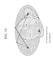
- the target detection system disclosed in FIG. 13 is also applied to cases where there N-pieces (three or more) of transmitters/receivers.
- Each of the transmitters/receivers 1, 2, 3, ---, N can capture the azimuth of the target M by the time reversal method described above. Therefore, the signals are integrated by a unit of azimuth for each of the transmitters/receivers, so that it is persistent for the condition of a low S/N ratio than the case of calculating the signal intensity by each distance.
- N Through integrating the reception results of each of the transmitters/receivers 1, 2, 3, ---, N, it becomes more persistent to the condition of a low S/N ratio.
- the position of the target M can be estimated by superimposing the azimuths of the target M acquired by each of the transmitters/receivers 1, 2, 3, ---, N. That is, even when the reflection from the target M is weak under an environment where the multiple reflections are prominent, it becomes possible to check the azimuth by executing the time reversal method shown in FIG. 15 . Based on this, it is possible to estimate the position of the target M by performing the superimposing processing on the acquired data of the corresponding point, and also possible to perform the superimposing processing on only the point of the target M even when the reflection from the target M is weak. Thus, the target M can be detected in the minimum time.
- the position of the target M can be estimated by using the N-pieces (three or more) of the transmitters/receivers 1, 2, 3, ---, N.
- the target detection system for detecting the target M including each of a plurality of target-detecting transmitters/receivers 1, 2, 3, ---, N constituted with radars, sonar, or lidars can estimate the position of the target M even when the reflected wave from the target M is weak under an environment where multiple reflections are prominent.
- the acquired reflected signals may be integrated by a unit of time instead of integration by a unit of azimuth or may be integrated in both the azimuth and time unit.
- the target detection system TS calculates the optimum transmission timing from the positional relation between the detection areas and the transmitters/receivers.
- the target M can be detected in the minimum time even in a case where the reflection from the target M is weak.
- the present invention is structured to place a plurality of same target detection transmitters/receivers constituted with radars, sonars, or lidars at different positions and to perform superimpose processing of information regarding waves reflected from a target acquired by each of the transmitters/receivers.
- a target detection transmitters/receivers constituted with radars, sonars, or lidars
- reception waves of higher level than surrounding noises can be acquired since the reception waves received at the plurality of transmitters/receivers are superimposed even though the level of the reception wave received at a single transmitter/receiver is weak.
- the second exemplary embodiment shows an example of a case where the transmitter/receiver layout module 11 places all the transmitters/receivers so as not to be arranged on a straight line.
- the distance to the target M on a straight line cannot be estimated if the three transmitters/receivers are lined on that straight line.
- the three transmitters/receivers are placed not to be lined on a straight line as shown in FIG. 6 .
- the layout state of the transmitters/receivers does not mean to place all of those transmitters/receivers 1, 2, 3, ---, N not to be lined on a straight line.
- the third exemplary embodiment shows a case of four or more transmitters/receivers that can only discriminate the azimuth for a specific rotation axis, in which the transmitter/receiver layout module 11 (see FIG. 1 ) arranges the transmitters/receivers in such a manner that all the transmitters/receivers 1, 2, 3, ---, N are not lined on a same plane.
- the azimuth of the target in the horizontal direction can be found from each of the sonars and the point where the azimuths on the horizontal direction of the sonars cross with each other is where the target exists.
- the azimuth in the perpendicular direction is still unknown, and it is the same even if there are three or more sonars.
- the azimuth on a surface shifted from the horizontal surface can be known.
- the target is within a fan shape (within a same distance) orthogonal to the horizontal surface.
- the target is within a fan shape that is obliquely orthogonal to the horizontal surface. It is possible to specify the position of the target at the intersection point between the intersection line of two or more former fan shapes (fan shapes orthogonal to the horizontal surface) and the latter fan shape (fan shape obliquely orthogonal to the horizontal surface).
- Other structures and operating effects are the same as the case of the first exemplary embodiment.
- the fourth exemplary embodiment is so characterized that the position/attitude control modules 1d, 2d, 3d, ---, 4d of each of the transmitters/receivers 1, 2, 3, ---, N shown in FIG. 1 are structured to have a function of adjusting the position not only according to instructions set by the transmitter/receiver layout module 11 but by making judgment by themselves according to instructions loaded in advance.
- the transmitting/receiving module 1a shown in FIG. 1 calculates the amplifying rate of amplitude in such a manner that the reception intensity in each of the transmitters/receivers 1, 2, 3, ---, N becomes the optimum from the candidate coordinate and the positional relation of each of the transmitters/receivers 1, 2, 3, ---, N, and transmits the transmission waveform information and the time reversal waveform information with the amplifying rate. This is to increase the signal intensity of the reception side by supplementing the attenuation of the waveform information caused as it travels the distance.
- the degree of attenuation can be calculated when the characteristic of the medium that transmits the transmission wave, each of the transmitters/receivers 1 to N, the target M, or the coordinate of the candidate of the target M (candidate coordinate) are known.
- the transmission intensity there is an upper limit in the energy that can be handled by the transmitter/receiver.
- An example of such change in the characteristic of the medium is generation of cavitation that is caused when the sonic wave intensity in a sonar is too large.
- a target detection system which includes:
- the target detection system depicted in Supplementary Note 1 which includes a third target-detecting transmitter/receiver including a same function as the function of each of the transmitters/receivers placed at a different position from the positions of each of the transmitters/receivers, wherein the position calculating module performs the superimposing processing on the information regarding the azimuth of the target acquired by at least three transmitters/receivers including the third transmitter/receiver.
- the position calculating module includes: an azimuth information superimposing processing function which performs superimposing processing on information regarding an azimuth of a given reception signal captured in each of the transmitters/receivers by transmission/reception of the transmission signal for the target on the basis of the layout positions of each of the transmitters/receivers; and a target position estimating function which estimates a position of a high reflection level in a crossing area of the azimuths acquired thereby as the position of the target.
- each of the transmitters/receivers includes: a reversal signal transmitting/receiving function which transmits a time reversal signal of a reflected signal by employing a time reversal method performed on the reflected signal from a target detection area towards the target detection area from each of the transmitters/receivers; and an azimuth specifying function which specifies an azimuth when the reflected signal for the transmission time reversal signal is acquired from the target as an azimuth at which the target exists.
- each of the transmitters includes:
- each of the transmitters/receivers is structured to operate according to an instruction of the signal output control module of the main control device and to transmit/receive a transmission signal regarding prescribed waveform information as a target detection signal at a different transmission timing from the timings of the other transmitter/receivers.
- each of the transmitters/receivers is structured to operate according to an instruction of the signal output control module of the main control device and to specify and transmit/receive a transmission signal regarding waveform information different from the transmission signals transmitted from the other transmitters/receivers as a target detection signal.
- the transmitting/receiving module of each of the plurality of transmitters/receivers includes: the reversal signal transmitting/receiving function which operates based on an instruction of the signal output control module of the main control device to specify the time reversal signal regarding time reversal waveform information reversed by the signal reversing module and to transmit/receive the reversal signal towards the target detection area; the azimuth specifying module which specifies an azimuth when the time reversal signal is reflected at the target and a time reversal reflected signal is acquired as the azimuth at which the target exists; and a function which transmits reception information regarding a first reception signal from the target corresponding to the azimuth along with the specified azimuth information to the position calculating module via the signal integrating module.
- the transmitter/receiver layout module of the main control device has a function which, when detecting the target by at least three or more pieces of the transmitters/receivers, gives an instruction to the position/attitude control setting module provided to one transmitter/receiver to place at least that one transmitter/receiver out of each of the transmitters/receivers at a position different from positions of the other transmitters/receivers that are placed on a same straight line.
- the transmitter/receiver layout module of the main control device has a function which gives an instruction to the position/attitude control setting module of at least one transmitter/receiver to place the axis thereof for discriminating the azimuth to be different from the axes of the other transmitters/receivers.
- the transmitter/receiver layout module of the main control device has an tilt setting instruction function which gives an instruction to the position/attitude control setting module of at least one transmitter/receiver out of the plurality of transmitters/receivers to set the azimuth rotating axis thereof to be tilted with respect to the azimuth rotating axes of the other transmitters/receivers that are placed at a prescribed interval.
- a target detection method used for a target detection system which includes at least two target-detecting transmitters/receivers capable of changing setting of detection azimuth placed at a prescribed interval and a main control device including a position calculating module which specifies a position of the target based on azimuth information of the target detected by each of the transmitters/receivers, wherein:
- the signal output control module sets transmission timings of each of the transmitters/receivers as same timings or different timings based on the waveform information of each of the transmitters/receivers, and designates the set transmission timings to each of the transmitters/receivers regarding.
- a non-transitory computer readable recording medium storing a detection information processing program used for a target detection system which includes at least two target-detecting transmitters/receivers capable of changing setting of detection azimuth placed at a prescribed interval and a main control device including a position calculating module which specifies a position of the target based on azimuth information of the target detected by each of the transmitters/receivers, the program causing a computer to execute:
- the non-transitory computer readable recording medium storing the detection information processing program depicted in Supplementary Note 21 used in the target detection system which includes, in addition to the two transmitters/receiver, a third target-detecting transmitter/receiver functioning in the same manner as the transmitters/receivers, the third transmitter/receiver being placed at a placing position different for each of the two transmitters/receivers and an azimuth rotating axis of the third transmitter/receiver being tilted with respect to the azimuth rotating axes of each of the two transmitters/receivers, wherein:
- a non-transitory computer readable recording medium storing a detection information processing program used for a target detection system which includes at least two target-detecting transmitters/receivers capable of changing setting of detection azimuth placed at a prescribed interval and a main control device including a position calculating module which specifies a position of the target based on azimuth information of the target detected by each of the transmitters/receivers, the program causing a computer to execute, for target azimuth information collecting processing executed by each of the transmitters/receivers:
- the present invention is a technique applicable to all the signal propagation fields such as a measuring device, a detection device, and the like which transmit/receive signals via gases, liquids, vacuums, or the like, and the usages thereof are extremely wide.
Landscapes
- Engineering & Computer Science (AREA)
- Radar, Positioning & Navigation (AREA)
- Remote Sensing (AREA)
- Physics & Mathematics (AREA)
- Computer Networks & Wireless Communication (AREA)
- General Physics & Mathematics (AREA)
- Electromagnetism (AREA)
- Acoustics & Sound (AREA)
- Measurement Of Velocity Or Position Using Acoustic Or Ultrasonic Waves (AREA)
- Position Fixing By Use Of Radio Waves (AREA)
- Radar Systems Or Details Thereof (AREA)
Applications Claiming Priority (1)
| Application Number | Priority Date | Filing Date | Title |
|---|---|---|---|
| JP2010198725A JP5640583B2 (ja) | 2010-09-06 | 2010-09-06 | 目標物探知システム、探知方法、及び探知情報処理プログラム |
Publications (3)
| Publication Number | Publication Date |
|---|---|
| EP2426508A2 true EP2426508A2 (de) | 2012-03-07 |
| EP2426508A3 EP2426508A3 (de) | 2012-05-16 |
| EP2426508B1 EP2426508B1 (de) | 2020-10-28 |
Family
ID=44759459
Family Applications (1)
| Application Number | Title | Priority Date | Filing Date |
|---|---|---|---|
| EP11180231.0A Active EP2426508B1 (de) | 2010-09-06 | 2011-09-06 | Zielerkennungssystem, Erkennungsverfahren und Verarbeitungsprogramm für die erkannte Information |
Country Status (3)
| Country | Link |
|---|---|
| US (1) | US20120056777A1 (de) |
| EP (1) | EP2426508B1 (de) |
| JP (1) | JP5640583B2 (de) |
Cited By (1)
| Publication number | Priority date | Publication date | Assignee | Title |
|---|---|---|---|---|
| US11057127B2 (en) | 2017-06-12 | 2021-07-06 | Elbit Systems Bmd And Land Ew-Elisra Ltd. | Method and system for identifying transmitter usage characteristics |
Families Citing this family (16)
| Publication number | Priority date | Publication date | Assignee | Title |
|---|---|---|---|---|
| US10168414B2 (en) * | 2014-07-17 | 2019-01-01 | Origin Wireless, Inc. | Wireless signals and techniques for determining locations of objects in multi-path environments |
| CN102903214B (zh) * | 2011-07-28 | 2014-08-20 | 富泰华工业(深圳)有限公司 | 具有遥控开关车门功能的汽车、遥控系统及遥控方法 |
| UA122209C2 (uk) * | 2014-07-29 | 2020-10-12 | Гевееф Месзюстеме Аг | Поліпшений витратомір на основі вимірювання часу проходження сигналу |
| JP6410614B2 (ja) * | 2015-01-09 | 2018-10-24 | 三菱電機株式会社 | 障害物検出装置および障害物検出方法 |
| KR101726940B1 (ko) * | 2015-04-22 | 2017-04-13 | 재단법인대구경북과학기술원 | 객체 식별 장치 및 방법 |
| CN105242259B (zh) * | 2015-09-08 | 2017-08-29 | 南京长江电子信息产业集团有限公司 | 时间序列分组滤波和幅度差值渐次逼近测向方法 |
| JP6727308B2 (ja) * | 2016-01-18 | 2020-07-22 | ゲーヴェーエフ メスシステメ アーゲーGwf Messsysteme Ag | 改良型ビーム整形音響信号伝搬時間差式流量計 |
| JP2017181417A (ja) * | 2016-03-31 | 2017-10-05 | 沖電気工業株式会社 | 情報処理装置、方法、システム |
| JP7012955B2 (ja) * | 2017-10-13 | 2022-01-31 | 三菱重工業株式会社 | 位置標定システム、および位置標定方法 |
| CN110749868B (zh) * | 2019-09-17 | 2021-09-14 | 珠海格力电器股份有限公司 | 一种雷达系统控制方法、装置、电子设备及可读存储介质 |
| CN110673115B (zh) * | 2019-09-25 | 2021-11-23 | 杭州飞步科技有限公司 | 雷达与组合导航系统的联合标定方法、装置、设备及介质 |
| EP3805777A1 (de) * | 2019-10-10 | 2021-04-14 | Toposens GmbH | Vorrichtungen und verfahren zur 3d-positionsbestimmung |
| CN111148323B (zh) * | 2019-12-25 | 2022-07-19 | 重庆特斯联智慧科技股份有限公司 | 一种基于目标感知的智慧建筑照明灯光调控方法与系统 |
| CN114528866B (zh) * | 2020-10-30 | 2026-01-23 | 深圳Tcl新技术有限公司 | 一种目标监测方法、智能终端及计算机可读存储介质 |
| JP2023101250A (ja) * | 2022-01-07 | 2023-07-20 | 日本電気株式会社 | ソーナー装置、方法、プログラム |
| CN114384525B (zh) * | 2022-01-07 | 2024-09-27 | 江苏科技大学 | 一种基于边界声反射的目标强度自测方法和自测系统 |
Citations (3)
| Publication number | Priority date | Publication date | Assignee | Title |
|---|---|---|---|---|
| JP2008249532A (ja) | 2007-03-30 | 2008-10-16 | Nec Corp | 探知装置及び探知用プログラム並びに探知方法 |
| JP2009041981A (ja) | 2007-08-07 | 2009-02-26 | Nissan Motor Co Ltd | 物体検出装置および方法、ならびに物体検出装置を備えた車両 |
| JP2010198725A (ja) | 2010-03-08 | 2010-09-09 | Toshiba Corp | 映像表示装置とその記録媒体の記録再生制御方法 |
Family Cites Families (11)
| Publication number | Priority date | Publication date | Assignee | Title |
|---|---|---|---|---|
| US3184739A (en) * | 1960-10-14 | 1965-05-18 | Franklin Frederick | Method of tracking radar targets in presence of jamming |
| US4806936A (en) * | 1986-06-20 | 1989-02-21 | Hughes Aircraft Company | Method of determining the position of multiple targets using bearing-only sensors |
| US5486833A (en) * | 1993-04-02 | 1996-01-23 | Barrett; Terence W. | Active signalling systems |
| US6225942B1 (en) * | 1999-07-30 | 2001-05-01 | Litton Systems, Inc. | Registration method for multiple sensor radar |
| GB0325622D0 (en) * | 2003-11-03 | 2003-12-10 | Cambridge Consultants | System for determining positional information |
| US7049960B2 (en) * | 2003-12-29 | 2006-05-23 | Lenovo (Singapore) Pte. Ltd | Method and system for locating objects |
| US7355545B2 (en) * | 2004-11-02 | 2008-04-08 | Bae Systems Information And Electronic Systems Integration Inc. | Through the wall ranging with triangulation using multiple spaced apart radars |
| JP2007303921A (ja) * | 2006-05-10 | 2007-11-22 | Kddi Corp | 信号源位置推定方法 |
| NL1032520C2 (nl) * | 2006-09-15 | 2008-03-18 | Thales Nederland Bv | Werkwijze en systeem voor het volgen van een object. |
| GB0822468D0 (en) * | 2008-12-10 | 2009-01-14 | Qinetiq Ltd | Method for mitigating the effects of clutter and interference on a radar system |
| EP2419755B1 (de) * | 2009-04-17 | 2017-05-24 | Raytheon Company | Verfahren und vorrichtungen zur integration von verteilten sensoren und flughafen-überwachungsradar zum mindern von blinden flecken |
-
2010
- 2010-09-06 JP JP2010198725A patent/JP5640583B2/ja active Active
-
2011
- 2011-09-06 EP EP11180231.0A patent/EP2426508B1/de active Active
- 2011-09-06 US US13/225,884 patent/US20120056777A1/en not_active Abandoned
Patent Citations (3)
| Publication number | Priority date | Publication date | Assignee | Title |
|---|---|---|---|---|
| JP2008249532A (ja) | 2007-03-30 | 2008-10-16 | Nec Corp | 探知装置及び探知用プログラム並びに探知方法 |
| JP2009041981A (ja) | 2007-08-07 | 2009-02-26 | Nissan Motor Co Ltd | 物体検出装置および方法、ならびに物体検出装置を備えた車両 |
| JP2010198725A (ja) | 2010-03-08 | 2010-09-09 | Toshiba Corp | 映像表示装置とその記録媒体の記録再生制御方法 |
Non-Patent Citations (1)
| Title |
|---|
| Y. TSURUGAYA, T. KIKUCHI, K. MIZUTANI: "Focal Depth Shifting of Phase-Conjugate Wave in Pekeris Waveguide", J. J. A. P., vol. 47, no. 5, 2008, pages 4339 - 4343, XP007910176, DOI: doi:10.1143/JJAP.47.4339 |
Cited By (1)
| Publication number | Priority date | Publication date | Assignee | Title |
|---|---|---|---|---|
| US11057127B2 (en) | 2017-06-12 | 2021-07-06 | Elbit Systems Bmd And Land Ew-Elisra Ltd. | Method and system for identifying transmitter usage characteristics |
Also Published As
| Publication number | Publication date |
|---|---|
| JP5640583B2 (ja) | 2014-12-17 |
| EP2426508A3 (de) | 2012-05-16 |
| US20120056777A1 (en) | 2012-03-08 |
| JP2012057963A (ja) | 2012-03-22 |
| EP2426508B1 (de) | 2020-10-28 |
Similar Documents
| Publication | Publication Date | Title |
|---|---|---|
| EP2426508B1 (de) | Zielerkennungssystem, Erkennungsverfahren und Verarbeitungsprogramm für die erkannte Information | |
| Whitcomb et al. | Advances in underwater robot vehicles for deep ocean exploration: Navigation, control, and survey operations | |
| US8279119B2 (en) | Systems and methods for transparency mapping using multipath signals | |
| US20170315234A1 (en) | Acoustic doppler system and method | |
| US11846704B2 (en) | Acoustic doppler system and method | |
| Alkhawaja et al. | Techniques of indoor positioning systems (IPS): A survey | |
| Jiang et al. | A survey of underwater acoustic SLAM system | |
| WO2009039161A2 (en) | Systems and methods for transparency mapping using multipath signals | |
| Kulkarni et al. | Radar based object detector using ultrasonic sensor | |
| CN108227744B (zh) | 一种水下机器人定位导航系统及定位导航方法 | |
| CN101866005A (zh) | 空间感测装置、移动载体与其定位与控制的运算方法 | |
| Williams et al. | A terrain-aided tracking algorithm for marine systems | |
| CN103837856A (zh) | 使用二次回声的传感器阵列的扩展角分辨率 | |
| JP2014035328A (ja) | 水中位置関係情報取得システム及び水中位置関係情報取得方法 | |
| Dzikowicz et al. | Demonstration of spiral wave front sonar for active localization | |
| AU2014298574B2 (en) | Device for assisting in the detection of objects placed on the ground from images of the ground taken by a wave reflection imaging device | |
| US7362655B1 (en) | Time-synchronous acoustic signal ranging system and method | |
| Lucifredi et al. | Gray whale target strength measurements and the analysis of the backscattered response | |
| Thong-un et al. | Improvement in airborne position measurements based on an ultrasonic linear-period-modulated wave by 1-bit signal processing | |
| Jaffré et al. | Ultra short baseline acoustic receiver/processor | |
| Git et al. | Acoustic tracking of moving marine targets using a single autonomous surface receiver | |
| CN113359182B (zh) | 一种深海热液喷口快速搜寻定位装置、方法及系统 | |
| Liu et al. | Underwater target passive acoustic localization method based on Hanbury Brown–Twiss interference | |
| Pyo et al. | Development of passive acoustic landmark using imaging sonar for AUV's localization | |
| KR20190112494A (ko) | 음파를 이용한 매설체의 매설 깊이 및 위치 측정 방법 및 측정 장치 |
Legal Events
| Date | Code | Title | Description |
|---|---|---|---|
| AK | Designated contracting states |
Kind code of ref document: A2 Designated state(s): AL AT BE BG CH CY CZ DE DK EE ES FI FR GB GR HR HU IE IS IT LI LT LU LV MC MK MT NL NO PL PT RO RS SE SI SK SM TR |
|
| AX | Request for extension of the european patent |
Extension state: BA ME |
|
| PUAI | Public reference made under article 153(3) epc to a published international application that has entered the european phase |
Free format text: ORIGINAL CODE: 0009012 |
|
| PUAL | Search report despatched |
Free format text: ORIGINAL CODE: 0009013 |
|
| AK | Designated contracting states |
Kind code of ref document: A3 Designated state(s): AL AT BE BG CH CY CZ DE DK EE ES FI FR GB GR HR HU IE IS IT LI LT LU LV MC MK MT NL NO PL PT RO RS SE SI SK SM TR |
|
| AX | Request for extension of the european patent |
Extension state: BA ME |
|
| RIC1 | Information provided on ipc code assigned before grant |
Ipc: G01S 15/89 20060101ALN20120410BHEP Ipc: G01S 17/87 20060101ALN20120410BHEP Ipc: G01S 7/536 20060101ALI20120410BHEP Ipc: G01S 7/527 20060101ALI20120410BHEP Ipc: G01S 7/292 20060101ALI20120410BHEP Ipc: G01S 15/46 20060101ALI20120410BHEP Ipc: G01S 13/46 20060101ALI20120410BHEP Ipc: G01S 15/87 20060101ALI20120410BHEP Ipc: G01S 13/87 20060101AFI20120410BHEP |
|
| 17P | Request for examination filed |
Effective date: 20121116 |
|
| 17Q | First examination report despatched |
Effective date: 20160620 |
|
| STAA | Information on the status of an ep patent application or granted ep patent |
Free format text: STATUS: EXAMINATION IS IN PROGRESS |
|
| GRAP | Despatch of communication of intention to grant a patent |
Free format text: ORIGINAL CODE: EPIDOSNIGR1 |
|
| STAA | Information on the status of an ep patent application or granted ep patent |
Free format text: STATUS: GRANT OF PATENT IS INTENDED |
|
| INTG | Intention to grant announced |
Effective date: 20200616 |
|
| GRAS | Grant fee paid |
Free format text: ORIGINAL CODE: EPIDOSNIGR3 |
|
| GRAA | (expected) grant |
Free format text: ORIGINAL CODE: 0009210 |
|
| STAA | Information on the status of an ep patent application or granted ep patent |
Free format text: STATUS: THE PATENT HAS BEEN GRANTED |
|
| AK | Designated contracting states |
Kind code of ref document: B1 Designated state(s): AL AT BE BG CH CY CZ DE DK EE ES FI FR GB GR HR HU IE IS IT LI LT LU LV MC MK MT NL NO PL PT RO RS SE SI SK SM TR |
|
| REG | Reference to a national code |
Ref country code: GB Ref legal event code: FG4D |
|
| REG | Reference to a national code |
Ref country code: CH Ref legal event code: EP |
|
| REG | Reference to a national code |
Ref country code: AT Ref legal event code: REF Ref document number: 1328760 Country of ref document: AT Kind code of ref document: T Effective date: 20201115 |
|
| REG | Reference to a national code |
Ref country code: DE Ref legal event code: R096 Ref document number: 602011069073 Country of ref document: DE |
|
| REG | Reference to a national code |
Ref country code: IE Ref legal event code: FG4D |
|
| REG | Reference to a national code |
Ref country code: AT Ref legal event code: MK05 Ref document number: 1328760 Country of ref document: AT Kind code of ref document: T Effective date: 20201028 |
|
| REG | Reference to a national code |
Ref country code: NL Ref legal event code: MP Effective date: 20201028 |
|
| PG25 | Lapsed in a contracting state [announced via postgrant information from national office to epo] |
Ref country code: GR Free format text: LAPSE BECAUSE OF FAILURE TO SUBMIT A TRANSLATION OF THE DESCRIPTION OR TO PAY THE FEE WITHIN THE PRESCRIBED TIME-LIMIT Effective date: 20210129 Ref country code: FI Free format text: LAPSE BECAUSE OF FAILURE TO SUBMIT A TRANSLATION OF THE DESCRIPTION OR TO PAY THE FEE WITHIN THE PRESCRIBED TIME-LIMIT Effective date: 20201028 Ref country code: RS Free format text: LAPSE BECAUSE OF FAILURE TO SUBMIT A TRANSLATION OF THE DESCRIPTION OR TO PAY THE FEE WITHIN THE PRESCRIBED TIME-LIMIT Effective date: 20201028 Ref country code: NL Free format text: LAPSE BECAUSE OF FAILURE TO SUBMIT A TRANSLATION OF THE DESCRIPTION OR TO PAY THE FEE WITHIN THE PRESCRIBED TIME-LIMIT Effective date: 20201028 Ref country code: NO Free format text: LAPSE BECAUSE OF FAILURE TO SUBMIT A TRANSLATION OF THE DESCRIPTION OR TO PAY THE FEE WITHIN THE PRESCRIBED TIME-LIMIT Effective date: 20210128 Ref country code: PT Free format text: LAPSE BECAUSE OF FAILURE TO SUBMIT A TRANSLATION OF THE DESCRIPTION OR TO PAY THE FEE WITHIN THE PRESCRIBED TIME-LIMIT Effective date: 20210301 |
|
| REG | Reference to a national code |
Ref country code: LT Ref legal event code: MG4D |
|
| PG25 | Lapsed in a contracting state [announced via postgrant information from national office to epo] |
Ref country code: AT Free format text: LAPSE BECAUSE OF FAILURE TO SUBMIT A TRANSLATION OF THE DESCRIPTION OR TO PAY THE FEE WITHIN THE PRESCRIBED TIME-LIMIT Effective date: 20201028 Ref country code: BG Free format text: LAPSE BECAUSE OF FAILURE TO SUBMIT A TRANSLATION OF THE DESCRIPTION OR TO PAY THE FEE WITHIN THE PRESCRIBED TIME-LIMIT Effective date: 20210128 Ref country code: ES Free format text: LAPSE BECAUSE OF FAILURE TO SUBMIT A TRANSLATION OF THE DESCRIPTION OR TO PAY THE FEE WITHIN THE PRESCRIBED TIME-LIMIT Effective date: 20201028 Ref country code: IS Free format text: LAPSE BECAUSE OF FAILURE TO SUBMIT A TRANSLATION OF THE DESCRIPTION OR TO PAY THE FEE WITHIN THE PRESCRIBED TIME-LIMIT Effective date: 20210228 Ref country code: LV Free format text: LAPSE BECAUSE OF FAILURE TO SUBMIT A TRANSLATION OF THE DESCRIPTION OR TO PAY THE FEE WITHIN THE PRESCRIBED TIME-LIMIT Effective date: 20201028 Ref country code: SE Free format text: LAPSE BECAUSE OF FAILURE TO SUBMIT A TRANSLATION OF THE DESCRIPTION OR TO PAY THE FEE WITHIN THE PRESCRIBED TIME-LIMIT Effective date: 20201028 Ref country code: PL Free format text: LAPSE BECAUSE OF FAILURE TO SUBMIT A TRANSLATION OF THE DESCRIPTION OR TO PAY THE FEE WITHIN THE PRESCRIBED TIME-LIMIT Effective date: 20201028 |
|
| PG25 | Lapsed in a contracting state [announced via postgrant information from national office to epo] |
Ref country code: HR Free format text: LAPSE BECAUSE OF FAILURE TO SUBMIT A TRANSLATION OF THE DESCRIPTION OR TO PAY THE FEE WITHIN THE PRESCRIBED TIME-LIMIT Effective date: 20201028 |
|
| REG | Reference to a national code |
Ref country code: DE Ref legal event code: R097 Ref document number: 602011069073 Country of ref document: DE |
|
| PG25 | Lapsed in a contracting state [announced via postgrant information from national office to epo] |
Ref country code: SM Free format text: LAPSE BECAUSE OF FAILURE TO SUBMIT A TRANSLATION OF THE DESCRIPTION OR TO PAY THE FEE WITHIN THE PRESCRIBED TIME-LIMIT Effective date: 20201028 Ref country code: EE Free format text: LAPSE BECAUSE OF FAILURE TO SUBMIT A TRANSLATION OF THE DESCRIPTION OR TO PAY THE FEE WITHIN THE PRESCRIBED TIME-LIMIT Effective date: 20201028 Ref country code: CZ Free format text: LAPSE BECAUSE OF FAILURE TO SUBMIT A TRANSLATION OF THE DESCRIPTION OR TO PAY THE FEE WITHIN THE PRESCRIBED TIME-LIMIT Effective date: 20201028 Ref country code: LT Free format text: LAPSE BECAUSE OF FAILURE TO SUBMIT A TRANSLATION OF THE DESCRIPTION OR TO PAY THE FEE WITHIN THE PRESCRIBED TIME-LIMIT Effective date: 20201028 Ref country code: SK Free format text: LAPSE BECAUSE OF FAILURE TO SUBMIT A TRANSLATION OF THE DESCRIPTION OR TO PAY THE FEE WITHIN THE PRESCRIBED TIME-LIMIT Effective date: 20201028 Ref country code: RO Free format text: LAPSE BECAUSE OF FAILURE TO SUBMIT A TRANSLATION OF THE DESCRIPTION OR TO PAY THE FEE WITHIN THE PRESCRIBED TIME-LIMIT Effective date: 20201028 |
|
| PG25 | Lapsed in a contracting state [announced via postgrant information from national office to epo] |
Ref country code: DK Free format text: LAPSE BECAUSE OF FAILURE TO SUBMIT A TRANSLATION OF THE DESCRIPTION OR TO PAY THE FEE WITHIN THE PRESCRIBED TIME-LIMIT Effective date: 20201028 |
|
| PLBE | No opposition filed within time limit |
Free format text: ORIGINAL CODE: 0009261 |
|
| STAA | Information on the status of an ep patent application or granted ep patent |
Free format text: STATUS: NO OPPOSITION FILED WITHIN TIME LIMIT |
|
| 26N | No opposition filed |
Effective date: 20210729 |
|
| PG25 | Lapsed in a contracting state [announced via postgrant information from national office to epo] |
Ref country code: AL Free format text: LAPSE BECAUSE OF FAILURE TO SUBMIT A TRANSLATION OF THE DESCRIPTION OR TO PAY THE FEE WITHIN THE PRESCRIBED TIME-LIMIT Effective date: 20201028 Ref country code: IT Free format text: LAPSE BECAUSE OF FAILURE TO SUBMIT A TRANSLATION OF THE DESCRIPTION OR TO PAY THE FEE WITHIN THE PRESCRIBED TIME-LIMIT Effective date: 20201028 |
|
| PG25 | Lapsed in a contracting state [announced via postgrant information from national office to epo] |
Ref country code: SI Free format text: LAPSE BECAUSE OF FAILURE TO SUBMIT A TRANSLATION OF THE DESCRIPTION OR TO PAY THE FEE WITHIN THE PRESCRIBED TIME-LIMIT Effective date: 20201028 |
|
| REG | Reference to a national code |
Ref country code: CH Ref legal event code: PL |
|
| REG | Reference to a national code |
Ref country code: BE Ref legal event code: MM Effective date: 20210930 |
|
| PG25 | Lapsed in a contracting state [announced via postgrant information from national office to epo] |
Ref country code: IS Free format text: LAPSE BECAUSE OF FAILURE TO SUBMIT A TRANSLATION OF THE DESCRIPTION OR TO PAY THE FEE WITHIN THE PRESCRIBED TIME-LIMIT Effective date: 20210228 Ref country code: MC Free format text: LAPSE BECAUSE OF FAILURE TO SUBMIT A TRANSLATION OF THE DESCRIPTION OR TO PAY THE FEE WITHIN THE PRESCRIBED TIME-LIMIT Effective date: 20201028 |
|
| PG25 | Lapsed in a contracting state [announced via postgrant information from national office to epo] |
Ref country code: LU Free format text: LAPSE BECAUSE OF NON-PAYMENT OF DUE FEES Effective date: 20210906 Ref country code: IE Free format text: LAPSE BECAUSE OF NON-PAYMENT OF DUE FEES Effective date: 20210906 Ref country code: BE Free format text: LAPSE BECAUSE OF NON-PAYMENT OF DUE FEES Effective date: 20210930 |
|
| PG25 | Lapsed in a contracting state [announced via postgrant information from national office to epo] |
Ref country code: LI Free format text: LAPSE BECAUSE OF NON-PAYMENT OF DUE FEES Effective date: 20210930 Ref country code: CH Free format text: LAPSE BECAUSE OF NON-PAYMENT OF DUE FEES Effective date: 20210930 |
|
| PG25 | Lapsed in a contracting state [announced via postgrant information from national office to epo] |
Ref country code: HU Free format text: LAPSE BECAUSE OF FAILURE TO SUBMIT A TRANSLATION OF THE DESCRIPTION OR TO PAY THE FEE WITHIN THE PRESCRIBED TIME-LIMIT; INVALID AB INITIO Effective date: 20110906 Ref country code: CY Free format text: LAPSE BECAUSE OF FAILURE TO SUBMIT A TRANSLATION OF THE DESCRIPTION OR TO PAY THE FEE WITHIN THE PRESCRIBED TIME-LIMIT Effective date: 20201028 |
|
| PG25 | Lapsed in a contracting state [announced via postgrant information from national office to epo] |
Ref country code: MK Free format text: LAPSE BECAUSE OF FAILURE TO SUBMIT A TRANSLATION OF THE DESCRIPTION OR TO PAY THE FEE WITHIN THE PRESCRIBED TIME-LIMIT Effective date: 20201028 |
|
| PG25 | Lapsed in a contracting state [announced via postgrant information from national office to epo] |
Ref country code: TR Free format text: LAPSE BECAUSE OF FAILURE TO SUBMIT A TRANSLATION OF THE DESCRIPTION OR TO PAY THE FEE WITHIN THE PRESCRIBED TIME-LIMIT Effective date: 20201028 |
|
| PG25 | Lapsed in a contracting state [announced via postgrant information from national office to epo] |
Ref country code: MT Free format text: LAPSE BECAUSE OF FAILURE TO SUBMIT A TRANSLATION OF THE DESCRIPTION OR TO PAY THE FEE WITHIN THE PRESCRIBED TIME-LIMIT Effective date: 20201028 |
|
| PGFP | Annual fee paid to national office [announced via postgrant information from national office to epo] |
Ref country code: DE Payment date: 20250919 Year of fee payment: 15 |
|
| PGFP | Annual fee paid to national office [announced via postgrant information from national office to epo] |
Ref country code: GB Payment date: 20250918 Year of fee payment: 15 |
|
| PGFP | Annual fee paid to national office [announced via postgrant information from national office to epo] |
Ref country code: FR Payment date: 20250922 Year of fee payment: 15 |