EP2425496B1 - Connecteur faible résistance pour carte de circuit imprimé - Google Patents
Connecteur faible résistance pour carte de circuit imprimé Download PDFInfo
- Publication number
- EP2425496B1 EP2425496B1 EP10716719.9A EP10716719A EP2425496B1 EP 2425496 B1 EP2425496 B1 EP 2425496B1 EP 10716719 A EP10716719 A EP 10716719A EP 2425496 B1 EP2425496 B1 EP 2425496B1
- Authority
- EP
- European Patent Office
- Prior art keywords
- connector
- connector body
- forward portion
- disposed
- connector according
- Prior art date
- Legal status (The legal status is an assumption and is not a legal conclusion. Google has not performed a legal analysis and makes no representation as to the accuracy of the status listed.)
- Not-in-force
Links
- 230000007704 transition Effects 0.000 claims description 15
- 239000013528 metallic particle Substances 0.000 claims description 2
- 238000001465 metallisation Methods 0.000 description 3
- SUOAMBOBSWRMNQ-UHFFFAOYSA-N 1,2,5-trichloro-3-(2,4-dichlorophenyl)benzene Chemical compound ClC1=CC(Cl)=CC=C1C1=CC(Cl)=CC(Cl)=C1Cl SUOAMBOBSWRMNQ-UHFFFAOYSA-N 0.000 description 2
- 238000012986 modification Methods 0.000 description 2
- 230000004048 modification Effects 0.000 description 2
- 230000032798 delamination Effects 0.000 description 1
- 239000000463 material Substances 0.000 description 1
- 239000002184 metal Substances 0.000 description 1
Images


Classifications
-
- H—ELECTRICITY
- H01—ELECTRIC ELEMENTS
- H01R—ELECTRICALLY-CONDUCTIVE CONNECTIONS; STRUCTURAL ASSOCIATIONS OF A PLURALITY OF MUTUALLY-INSULATED ELECTRICAL CONNECTING ELEMENTS; COUPLING DEVICES; CURRENT COLLECTORS
- H01R24/00—Two-part coupling devices, or either of their cooperating parts, characterised by their overall structure
- H01R24/38—Two-part coupling devices, or either of their cooperating parts, characterised by their overall structure having concentrically or coaxially arranged contacts
- H01R24/40—Two-part coupling devices, or either of their cooperating parts, characterised by their overall structure having concentrically or coaxially arranged contacts specially adapted for high frequency
- H01R24/50—Two-part coupling devices, or either of their cooperating parts, characterised by their overall structure having concentrically or coaxially arranged contacts specially adapted for high frequency mounted on a PCB [Printed Circuit Board]
-
- H—ELECTRICITY
- H01—ELECTRIC ELEMENTS
- H01R—ELECTRICALLY-CONDUCTIVE CONNECTIONS; STRUCTURAL ASSOCIATIONS OF A PLURALITY OF MUTUALLY-INSULATED ELECTRICAL CONNECTING ELEMENTS; COUPLING DEVICES; CURRENT COLLECTORS
- H01R13/00—Details of coupling devices of the kinds covered by groups H01R12/70 or H01R24/00 - H01R33/00
- H01R13/62—Means for facilitating engagement or disengagement of coupling parts or for holding them in engagement
- H01R13/627—Snap or like fastening
- H01R13/6271—Latching means integral with the housing
- H01R13/6273—Latching means integral with the housing comprising two latching arms
-
- H—ELECTRICITY
- H01—ELECTRIC ELEMENTS
- H01R—ELECTRICALLY-CONDUCTIVE CONNECTIONS; STRUCTURAL ASSOCIATIONS OF A PLURALITY OF MUTUALLY-INSULATED ELECTRICAL CONNECTING ELEMENTS; COUPLING DEVICES; CURRENT COLLECTORS
- H01R13/00—Details of coupling devices of the kinds covered by groups H01R12/70 or H01R24/00 - H01R33/00
- H01R13/62—Means for facilitating engagement or disengagement of coupling parts or for holding them in engagement
- H01R13/625—Casing or ring with bayonet engagement
-
- H—ELECTRICITY
- H01—ELECTRIC ELEMENTS
- H01R—ELECTRICALLY-CONDUCTIVE CONNECTIONS; STRUCTURAL ASSOCIATIONS OF A PLURALITY OF MUTUALLY-INSULATED ELECTRICAL CONNECTING ELEMENTS; COUPLING DEVICES; CURRENT COLLECTORS
- H01R2103/00—Two poles
Definitions
- the present invention relates generally to low resistance connectors for printed circuit boards, and particularly to connectors that require lower resistance to unmate the connector from printed circuit boards and only when the unmating of the connector from the printed circuit board is desired.
- Coaxial connectors are used to connect with electrical connectors on printed circuit boards (PCBs).
- the electrical connectors on the PCBs are soldered to metallic traces on the PCBs, which in turn are laminated to the board material.
- Typical electrical connections between the PCB connector and coaxial connectors are of the push-pull type. These connections are known to cause a delamination of the soldered connections and the metallic traces on the PCBs themselves when the connectors are unmated due to the typically higher resistance required to unmate them.
- EP-A-0971456 discloses a connector according to the preamble of claim 1 and according to the preamble of claim 7.
- an electrical connector for a printed circuit board that includes a main body having a forward portion and a rearward portion, a front end and a back end and an opening extending therebetween, the front end disposed on the forward portion and the back end disposed on the rearward portion; the forward portion having a generally circular cross section, the forward portion having at least one inclined surface extending from the front end to a middle portion of the forward portion, and at least one generally straight portion adjacent the inclined surface creating a ledge between the inclined surface and the straight portion.
- the electrical connector has two inclined surfaces, two generally straight portions and two ledges.
- an electrical connector for connecting a printed circuit board and a coaxial cable that includes a first connector body having a forward portion and a rearward portion, a front end and a back end and an opening extending therebetween, the front end disposed on the forward portion and the back end disposed on the rearward portion, the forward portion having a generally circular cross section, the forward portion having at least one inclined surface extending from the front end to a middle portion of the forward portion, and at least one generally straight portion adjacent the inclined surface creating a ledge between the inclined surface and the straight portion and a second connector body having an outer sleeve, the sleeve having a front end and a back end and an opening therebetween, the opening configured to receive at least a portion of the forward portion of the first connector body, the outer sleeve having a least one arm extending between the front end and a middle portion and configured to engage the inclined portion and ledge of the forward portion to prevent axial movement of the first and second connector bodies relative to one another when
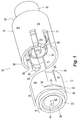
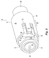
- an electrical connector 10 has a first connector body 12 and a second connector body 14.
- the first connector body 12 has a forward portion 16 and a rearward portion 18.
- the forward portion 16 has a front end 20 and the rearward portion 18 has a back end 22, with an opening 24 extending therebetween.
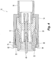
- the forward portion 16 has a generally circular cross section with at least one inclined surface 26 extending from the front end 20 toward a middle portion 28 of the front portion 16.
- the inclined surface 26 inclines toward the outer surface 30 of first connector body 12 from the front end 20.
- the inclined surface 26 transitions into the outer surface 30, where there is a generally straight portion 32 that creates a ledge 34 between the generally straight portion 32 and outer surface 30, that in turn is adjacent the inclined surface 26.
- the generally straight portion 32 transitions into the outer surface 30 of the first connector body 12 at transition portions 36 at either end of the generally straight portion 32.
- the transition portions 36 have a radius that is preferably different from the diameter of the outer surface 30 of the first connector body 12.
- the radius of the transition portion 36 is about 0.025 inches, but could range anywhere from 0.00 inches to 0.050 inches.
- the radius of the transition portion 36 is important for the operation of the electrical connector 10, as described in more detail below. It should also be noted that the radius and range of the radius can vary with size of the connector.
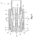
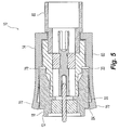
- the rearward portion 18 of first connector body 12 also has a generally circular cross section and has a diameter that is generally smaller than that of the forward portion 16. However the diameter of rearward portion 18 may also be the same as or larger than the radius of the forward portion 16. As is best illustrated in Fig. 3 , the first connector body 12 may also have a center contact 40 and a dielectric member 42 to hold and center the center contact 40. The back end 22 of rearward portion 18 of the first connector body 12 and the center contact 40 are soldered to the PCB as is known in the art. For example as illustrated in Fig. 8 , a PCB 90 is illustrated.
- the PCB 90 has an opening 92 into which the center contact 40 is soldered so that it makes contact with the signal metallization 94 and the back end 22 is soldered to the ground metallization 96.
- the metallizations 94,96 are then electrically connected to metal traces.
- the electrical connector 10 also includes the second connector body 14.
- Second connector body 14 has an outer sleeve 60 with a front end 62 and a back end 64 and an opening 66 extending therebetween.
- the outer sleeve 60 may be knurled or grooved to assist in gripping the second connector body 14.
- the second connector body 14 has a middle portion 68, where two cantilevered arms 70 extend toward the front end 62.
- the arms 70 are essentially a portion of the outer sleeve, as the arms 70 have the same outer diameter as the remainder of the outer sleeve 60 and are defined by two slots 72 extending from the front end 62 to the middle portion 68.
- the opening 66 preferably has two portions, a front inner portion 74 and a rear inner portion 76.
- the front inner portion 74 has a first diameter that is larger than the second diameter of the rear inner portion 76, thereby creating a forward facing surface 78 in the middle portion 68.
- the rear inner portion 76 is configured to receive a cable adapter, center contact and dielectric 80.
- the cable adapter, center contact and dielectric 80 are standard parts, known to those of skill in the art.
- the second connector body 14 is attached to a cable (not shown) and the cable adapter in a standard way.
- the arms 70 are, by their nature, flexible and are able to flex outward (away from the opening 66 ).
- the arms 70 preferably have at the front end 82 a downward extending projections 84 (and, in particular, rearward facing surfaces 88 ) that engage the ledge 34 of the first connector body 12.
- the arms 70 also have a chamfered portion 86 on the front end 82 to assist in guiding the arms 70 onto the at least one inclined surface 26.
- the arms 70 engage the inclined surface 26 (see Fig. 2 ) and are flexed outwardly.
- the arms 70 are flexed further outward until the downward extending projections 84 go over the ledge 34 and make contact with the generally straight portion 32.
- the engagement of the downward extending projections 84 with the ledge 34 prevents the second connector body 14 from being pulled axially away from the first connector body 12.
- the two connector bodies 12,14 cannot be pulled apart and the force required to connect them to one another is very low.
- the user must merely rotate the connector bodies 12,14 relative to one another.
- the two connector bodies 12,14 are fully engaged.
- Fig. 4 illustrates that the two connector bodies 12,14 have begun to be rotated relative to one another.
- the arms 70 rotate and move along the generally straight portion 32, the arms 70 begin to flex outward.
- the arms 70 approach the transition portions 36, the arms 70 flex outwardly even more.
- the second connector body 14 can be moved axially relative to the first connector body 12 and unmated with little force (generally limited to the friction of the downward extending projections 84 on the first connector body 12 ).
- FIG. 6 An alternative embodiment of a second connector body 114 is illustrated in Fig. 6 .
- the second connector body 114 is similar to the second connector body 14 discussed above, but has an elastomeric gasket 120 that engages the forward facing surface 178 in the middle portion 168.
- the elastomeric gasket 120 is preferably impregnated with metallic particles to assist in preventing leakage of the electrical signal from the connector.
- the elastomeric gasket 120 allows the connector to be sealed against the elements when the first connector body is inserted into the opening 166 and the front end of the first connector body engages the elastomeric gasket 120 and compresses it against the forward facing surface 178.
- the ledge 34 and the rearward facing surfaces 88 of downward extending projections 84 of connector 10 are illustrated as being perpendicular to its axial axis.
- the ledge 34 and the rearward facing surfaces 88 of downward extending projections 84 are slanted in a rearward direction to allow for easier engagement of the ledge 34 by the rearward facing surfaces of downward extending projections 84.
- rearward facing surfaces 188 of downward extending projections 184 have an angle other than 90 degrees with the front inner portion 174 (the ledge 34 would have a corresponding angle, but is not illustrated).
- Such a configuration compensates for any variations in the tolerances of the first and second connector bodies.
- FIG. 7 Another alternative embodiment of a second connector body 214 is illustrated in Fig. 7 .
- the second connector body 214 has a wave spring washer 220 also disposed against the forward facing surface 278 in the middle portion 268, where it further limits the axial movement of the connector bodies relative to one another.
Landscapes
- Details Of Connecting Devices For Male And Female Coupling (AREA)
- Coupling Device And Connection With Printed Circuit (AREA)
Claims (13)
- Connecteur (10) pour carte (90) à circuit imprimé, comportant :un corps principal (12) doté d'une partie avant (16) présentant une surface extérieure (30) et d'une partie arrière (18), d'une extrémité avant (20) et d'une extrémité arrière (22) et d'une ouverture (24) s'étendant entre celles-ci, l'extrémité avant (20) étant disposée sur la partie avant (16) et l'extrémité arrière (22) disposée sur la partie arrière (18) ; la partie avant (16) présentant une section droite généralement circulaire ;la partie avant (16) présentant au moins une surface inclinée (26) s'étendant de l'extrémité avant (20) jusqu'à une partie médiane (28) de la partie avant (16),caractérisé en ce que la ou les surfaces inclinées (26) s'inclinent vers et s'incorpore à la surface extérieure (30) entre l'extrémité avant (20) et la partie médiane (28) de la partie avant (16) ; et
en ce qu'au moins une partie généralement rectiligne (32) adjacente à l'endroit où la surface inclinée (26) s'incorpore à la surface extérieure (30) crée un rebord (34) entre l'endroit où la surface inclinée (26) s'incorpore à la surface extérieure (30) et la partie rectiligne (32), et la partie rectiligne (32) s'incorporant à la surface extérieure (30) de la partie avant (16) du corps principal (12) au niveau de parties (36) de transition. - Connecteur selon la revendication 1, la partie avant (16) étant dotée d'une surface extérieure présentant un premier diamètre extérieur et la partie arrière (18) étant dotée d'une surface extérieure présentant un deuxième diamètre, le premier diamètre étant différent du deuxième diamètre.
- Connecteur selon la revendication 1, la partie généralement rectiligne (32) et le rebord (34) formant un angle autre que 90 degrés.
- Connecteur selon la revendication 1, la partie (36) de transition présentant un rayon prédéterminé.
- Connecteur selon la revendication 1, la partie arrière (18) pouvant être reliée électriquement à des connexions de tracés de carte à circuit imprimé.
- Connecteur selon la revendication 1, l'ouverture (24) étant configurée pour recevoir un connecteur femelle de câble.
- Connecteur électrique (10) destiné à relier une carte (90) à circuit imprimé et un câble coaxial, comportant :un premier corps (12) de connecteur doté d'une partie avant (16) et d'une partie arrière (18), d'une extrémité avant (20) et d'une extrémité arrière (22) et d'une ouverture (24) s'étendant entre celles-ci, l'extrémité avant (20) étant disposée sur la partie avant (16) et l'extrémité arrière (22) étant disposée sur la partie arrière (18), la partie avant (16) présentant une section droite généralement circulaire, la partie avant (16) présentant au moins une surface inclinée (26) s'étendant de l'extrémité avant (20) jusqu'à une partie médiane (28) de la partie avant, et au moins une partie généralement rectiligne (32) adjacente à la surface inclinée (26) créant un rebord (34) entre la surface inclinée (26) et la partie rectiligne (32) ; etun deuxième corps (14, 114, 214) de connecteur ;caractérisé en ce que
le deuxième corps (14, 114, 214) de connecteur est doté d'un manchon extérieur (60), le manchon (60) présentant une extrémité avant (62) et une extrémité arrière (64) et une ouverture (66) entre celles-ci, l'ouverture (66) étant configurée pour recevoir au moins une partie de la partie avant (16) du premier corps (12) de connecteur, le manchon extérieur (60) étant doté d'au moins un bras (70) s'étendant entre l'extrémité avant (62) et une partie médiane (68) et configuré pour coopérer avec la partie inclinée (26) et le rebord (34) de la partie avant (16) pour empêcher un mouvement axial des premier et deuxième corps de connecteur l'un par rapport à l'autre lorsque le premier corps (12) de connecteur est disposé dans l'ouverture (66) du deuxième corps de connecteur. - Connecteur électrique selon la revendication 7, une rotation du deuxième corps (14, 114, 214) de connecteur par rapport au premier corps (12) de connecteur écartant le ou les bras (70) de la ou des parties généralement rectilignes (32) et du rebord (34), les premier et deuxième corps de connecteur pouvant ainsi être éloignés l'un de l'autre dans une direction axiale.
- Connecteur électrique selon la revendication 7, le deuxième corps (14, 114, 214) de connecteur présentant une surface (78) orientée vers l'avant s'étendant au moins partiellement autour de l'ouverture (55) et disposée entre l'extrémité avant (62) et l'extrémité arrière (64) et coopérant avec l'extrémité avant (20) du premier corps (12) de connecteur lorsque le premier corps (12) de connecteur est entièrement inséré dans le deuxième corps (14, 114, 214) de connecteur.
- Connecteur électrique selon la revendication 7, le premier corps (12) de connecteur comprenant une partie en retrait circonférentiellement autour de l'extrémité avant (20) et un élément élastique disposé dans celle-ci.
- Connecteur électrique selon la revendication 7, l'élément élastique comprenant des particules métalliques pour empêcher une fuite de signal.
- Connecteur électrique selon la revendication 7, le bras (70) comprenant une partie (4) s'étendant vers le bas pour coopérer avec le rebord (34).
- Connecteur électrique selon la revendication 7, comportant en outre une rondelle élastique ondulée (220) disposée entre le premier corps de connecteur et le deuxième corps de connecteur.
Applications Claiming Priority (2)
| Application Number | Priority Date | Filing Date | Title |
|---|---|---|---|
| US12/433,302 US7914347B2 (en) | 2009-04-30 | 2009-04-30 | Low resistance connector for printed circuit board |
| PCT/US2010/032888 WO2010127065A1 (fr) | 2009-04-30 | 2010-04-29 | Connecteur faible resistance pour carte de circuit imprime |
Publications (2)
| Publication Number | Publication Date |
|---|---|
| EP2425496A1 EP2425496A1 (fr) | 2012-03-07 |
| EP2425496B1 true EP2425496B1 (fr) | 2016-07-27 |
Family
ID=42556932
Family Applications (1)
| Application Number | Title | Priority Date | Filing Date |
|---|---|---|---|
| EP10716719.9A Not-in-force EP2425496B1 (fr) | 2009-04-30 | 2010-04-29 | Connecteur faible résistance pour carte de circuit imprimé |
Country Status (6)
| Country | Link |
|---|---|
| US (1) | US7914347B2 (fr) |
| EP (1) | EP2425496B1 (fr) |
| CN (1) | CN102498619B (fr) |
| DK (1) | DK2425496T3 (fr) |
| TW (1) | TWI533531B (fr) |
| WO (1) | WO2010127065A1 (fr) |
Families Citing this family (27)
| Publication number | Priority date | Publication date | Assignee | Title |
|---|---|---|---|---|
| FR2935202B1 (fr) * | 2008-08-21 | 2010-10-22 | Labinal | Dispositif de connexion entre un cable electrique et une structure conductrice, notamment pour circuit de retour de courant |
| CN201667478U (zh) * | 2009-11-10 | 2010-12-08 | 富士康(昆山)电脑接插件有限公司 | 转接器 |
| DE102009060423A1 (de) * | 2009-12-22 | 2011-07-21 | dspace digital signal processing and control engineering GmbH, 33102 | Kontaktierungsvorrichtung |
| US8668504B2 (en) | 2011-07-05 | 2014-03-11 | Dave Smith Chevrolet Oldsmobile Pontiac Cadillac, Inc. | Threadless light bulb socket |
| DE112012003093T5 (de) * | 2011-07-25 | 2014-06-12 | Honda Motor Co., Ltd. | Elektrischer Verbinder |
| DE102011056466A1 (de) * | 2011-12-15 | 2013-06-20 | Telegärtner Karl Gärtner GmbH | Koaxial-Steckverbinderanordnung |
| US8845368B1 (en) * | 2012-08-31 | 2014-09-30 | Amazon Technologies, Inc. | Electrical connectors |
| JP5883366B2 (ja) * | 2012-09-06 | 2016-03-15 | ヒロセ電機株式会社 | 電気コネクタ組立体 |
| CN102842816B (zh) * | 2012-09-28 | 2014-12-31 | 苏州瑞可达连接系统股份有限公司 | 一种射频同轴连接机构 |
| US8784130B2 (en) * | 2012-11-06 | 2014-07-22 | Solarcity Corporation | Supply side backfeed meter socket adapter |
| CN103280666B (zh) * | 2013-04-27 | 2015-11-25 | 中航光电科技股份有限公司 | 水下分离电连接器组件及其插头 |
| DE102014101297B4 (de) * | 2014-02-03 | 2017-06-22 | Telegärtner Karl Gärtner GmbH | Koaxial-Steckverbinderanordnung |
| DE102014001546B4 (de) * | 2014-02-07 | 2017-02-16 | Wolfgang Kunzweiler | Steckkupplung |
| US9478929B2 (en) | 2014-06-23 | 2016-10-25 | Ken Smith | Light bulb receptacles and light bulb sockets |
| JP6074753B2 (ja) * | 2014-11-25 | 2017-02-08 | ヒロセ電機株式会社 | 電気コネクタ組立体 |
| CN106560957B (zh) * | 2015-10-06 | 2020-04-24 | 富士康(昆山)电脑接插件有限公司 | 电源连接器转接头及其组装方法 |
| JP6319280B2 (ja) * | 2015-12-09 | 2018-05-09 | 第一精工株式会社 | コネクタ装置 |
| USD843320S1 (en) | 2016-08-26 | 2019-03-19 | HARTING Electronics GmbH | Electrical plug connector |
| WO2018057642A1 (fr) * | 2016-09-20 | 2018-03-29 | Nite Ize, Inc. | Dispositif de manchon de cordon, outil d'installation et procédé d'utilisation |
| JP6811654B2 (ja) * | 2017-03-14 | 2021-01-13 | 日立オートモティブシステムズ株式会社 | コネクタ |
| KR101921128B1 (ko) * | 2018-04-27 | 2018-11-22 | 주식회사 엠피디 | 리셉터클 커넥터 |
| CN111740272B (zh) * | 2019-03-25 | 2021-11-26 | 珠海保税区光联通讯技术有限公司 | 连接器 |
| DE102019117473A1 (de) * | 2019-06-28 | 2020-12-31 | Tesat-Spacecom Gmbh & Co. Kg | Schaltungsanordnung bestehend aus zwei miteinander verbundenen Hochfrequenzkomponenten |
| CN112366474B (zh) * | 2020-10-31 | 2021-12-03 | 贵州电网有限责任公司 | 一种串并联混合方式供电的直流电源系统 |
| JP7679247B2 (ja) * | 2021-07-15 | 2025-05-19 | リズム株式会社 | 回路基板の接続用端子 |
| US20230133043A1 (en) * | 2021-11-02 | 2023-05-04 | Comtest Networks Inc. | Bnc with intergrated switch |
| CN121097424A (zh) * | 2025-11-12 | 2025-12-09 | 中航光电科技股份有限公司 | 一种板间浮动连接器 |
Family Cites Families (24)
| Publication number | Priority date | Publication date | Assignee | Title |
|---|---|---|---|---|
| US3546658A (en) * | 1968-04-22 | 1970-12-08 | United Carr Inc | Connector with splined backshell |
| US4211461A (en) * | 1978-11-27 | 1980-07-08 | Industrial Electronic Hardware Corp. | Axially mating cable connector |
| JPS601503Y2 (ja) * | 1979-03-16 | 1985-01-16 | アルプス電気株式会社 | コネクタ |
| US5776116A (en) | 1983-01-24 | 1998-07-07 | Icu Medical, Inc. | Medical connector |
| JPS62285378A (ja) * | 1986-06-04 | 1987-12-11 | ヒロセ電機株式会社 | 雌形同軸コネクタとその製造方法 |
| US4932673A (en) * | 1988-02-01 | 1990-06-12 | Hughes Aircraft Company | Emi suppression gasket for millimeter waveguides |
| US4881912A (en) | 1988-04-29 | 1989-11-21 | Specialty Connector Company, Inc. | High voltage coaxial connector |
| DE29517358U1 (de) | 1995-11-02 | 1996-01-11 | Harting Elektronik Gmbh, 32339 Espelkamp | Koaxial Steckverbindung |
| US6164977A (en) * | 1998-02-09 | 2000-12-26 | Itt Manufacturing Enterprises, Inc. | Standoff board-mounted coaxial connector |
| US5993239A (en) * | 1998-07-08 | 1999-11-30 | Osram Sylvania Inc. | Positive latch connector |
| US6062607A (en) | 1998-07-17 | 2000-05-16 | Proprietary Technology, Inc. | Quick connector with secondary latch confirming feature |
| US6450829B1 (en) | 2000-12-15 | 2002-09-17 | Tyco Electronics Canada, Ltd. | Snap-on plug coaxial connector |
| US6409534B1 (en) | 2001-01-08 | 2002-06-25 | Tyco Electronics Canada Ltd. | Coax cable connector assembly with latching housing |
| US6361348B1 (en) | 2001-01-15 | 2002-03-26 | Tyco Electronics Corporation | Right angle, snap on coaxial electrical connector |
| USD456355S1 (en) * | 2001-03-02 | 2002-04-30 | Smk Corporation | Coaxial connector |
| TW545726U (en) | 2002-09-25 | 2003-08-01 | Hon Hai Prec Ind Co Ltd | Electrical connector |
| TW562291U (en) | 2002-12-04 | 2003-11-11 | Hon Hai Prec Ind Co Ltd | Radio frequency connector assembly |
| US7029286B2 (en) * | 2003-02-07 | 2006-04-18 | Tyco Electronics Corporation | Plastic housings for jack assemblies |
| US6955563B1 (en) | 2005-02-08 | 2005-10-18 | Croan Quinn F | RJ type modular connector for coaxial cables |
| US7234956B2 (en) | 2005-09-02 | 2007-06-26 | Kauffman George M | Electrical connector with dual independent coupling means |
| CN2847596Y (zh) | 2005-11-04 | 2006-12-13 | 西安科耐特科技有限责任公司 | 快插自锁射频同轴连接器 |
| US20070249236A1 (en) * | 2006-04-20 | 2007-10-25 | Randy Petak | System for ensuring electrical continuity in connection between pre-wired electrical harnesses and conduits |
| US7335058B1 (en) | 2006-12-13 | 2008-02-26 | Corning Gilbert, Inc. | Snap-fit connector assembly |
| KR100818644B1 (ko) * | 2007-01-31 | 2008-04-02 | 삼성전자주식회사 | 하드디스크 드라이브의 액추에이터 래치장치 및 그를구비한 하드디스크 드라이브 |
-
2009
- 2009-04-30 US US12/433,302 patent/US7914347B2/en active Active
-
2010
- 2010-04-28 TW TW099113594A patent/TWI533531B/zh not_active IP Right Cessation
- 2010-04-29 CN CN201080027462.2A patent/CN102498619B/zh not_active Expired - Fee Related
- 2010-04-29 EP EP10716719.9A patent/EP2425496B1/fr not_active Not-in-force
- 2010-04-29 WO PCT/US2010/032888 patent/WO2010127065A1/fr not_active Ceased
- 2010-04-29 DK DK10716719.9T patent/DK2425496T3/en active
Also Published As
| Publication number | Publication date |
|---|---|
| TW201112523A (en) | 2011-04-01 |
| CN102498619B (zh) | 2015-01-28 |
| TWI533531B (zh) | 2016-05-11 |
| DK2425496T3 (en) | 2016-11-14 |
| US20100279536A1 (en) | 2010-11-04 |
| US7914347B2 (en) | 2011-03-29 |
| WO2010127065A1 (fr) | 2010-11-04 |
| CN102498619A (zh) | 2012-06-13 |
| EP2425496A1 (fr) | 2012-03-07 |
Similar Documents
| Publication | Publication Date | Title |
|---|---|---|
| EP2425496B1 (fr) | Connecteur faible résistance pour carte de circuit imprimé | |
| US20100304579A1 (en) | Low Resistance Connector For Printed Circuit Board | |
| US7758370B1 (en) | Quick release electrical connector | |
| EP1854182B1 (fr) | Connecteur électronique | |
| EP2304847B1 (fr) | Connecteur de câble coaxial encliquetable | |
| EP2636105B1 (fr) | Connecteur électrique avec organe de mise à la terre | |
| US8628359B2 (en) | Connector and connector unit | |
| US8512073B2 (en) | Coaxial electric connector | |
| JP4510770B2 (ja) | ケーブル把持部を備える同軸コネクタ | |
| EP2625749B1 (fr) | Système de connexion | |
| US20130203288A1 (en) | Coaxial angled adapter | |
| TW201316628A (zh) | 具有整合射頻干擾與接地遮蔽的同軸電纜接頭 | |
| US20130157505A1 (en) | Coaxial connector | |
| WO2019046517A1 (fr) | Connecteur de câble coaxial à écrou de couplage de mise à la terre | |
| US20180316103A1 (en) | Multi-pin connector block assembly | |
| KR20220133292A (ko) | 접촉 조립체의 탄성 암을 스터빙으로부터 보호하기 위한 보호 부재 | |
| US8206189B2 (en) | Inner terminal | |
| US20190181588A1 (en) | Connector device and coaxial connector | |
| US12525750B2 (en) | Round plug connector comprising a shield connection | |
| CN210489873U (zh) | 同轴连接器及板对板连接器组件 | |
| US20180375258A1 (en) | Self-aligning cable mating connector | |
| EP3616267B1 (fr) | Ensemble broche de connecteur radiofréquence (rf) | |
| JP6045307B2 (ja) | 同軸コネクタ | |
| US20070228839A1 (en) | Connector | |
| CN108767542B (zh) | 连接器 |
Legal Events
| Date | Code | Title | Description |
|---|---|---|---|
| PUAI | Public reference made under article 153(3) epc to a published international application that has entered the european phase |
Free format text: ORIGINAL CODE: 0009012 |
|
| 17P | Request for examination filed |
Effective date: 20111027 |
|
| AK | Designated contracting states |
Kind code of ref document: A1 Designated state(s): AT BE BG CH CY CZ DE DK EE ES FI FR GB GR HR HU IE IS IT LI LT LU LV MC MK MT NL NO PL PT RO SE SI SK SM TR |
|
| DAX | Request for extension of the european patent (deleted) | ||
| GRAP | Despatch of communication of intention to grant a patent |
Free format text: ORIGINAL CODE: EPIDOSNIGR1 |
|
| RIC1 | Information provided on ipc code assigned before grant |
Ipc: H01R 13/627 20060101AFI20150511BHEP Ipc: H01R 13/646 20110101ALI20150511BHEP Ipc: H01R 24/50 20110101ALI20150511BHEP Ipc: H01R 13/625 20060101ALI20150511BHEP Ipc: H01R 103/00 20060101ALI20150511BHEP Ipc: H01R 13/635 20060101ALI20150511BHEP |
|
| INTG | Intention to grant announced |
Effective date: 20150617 |
|
| GRAS | Grant fee paid |
Free format text: ORIGINAL CODE: EPIDOSNIGR3 |
|
| INTG | Intention to grant announced |
Effective date: 20160107 |
|
| GRAA | (expected) grant |
Free format text: ORIGINAL CODE: 0009210 |
|
| AK | Designated contracting states |
Kind code of ref document: B1 Designated state(s): AT BE BG CH CY CZ DE DK EE ES FI FR GB GR HR HU IE IS IT LI LT LU LV MC MK MT NL NO PL PT RO SE SI SK SM TR |
|
| REG | Reference to a national code |
Ref country code: GB Ref legal event code: FG4D |
|
| REG | Reference to a national code |
Ref country code: CH Ref legal event code: EP |
|
| REG | Reference to a national code |
Ref country code: AT Ref legal event code: REF Ref document number: 816472 Country of ref document: AT Kind code of ref document: T Effective date: 20160815 |
|
| REG | Reference to a national code |
Ref country code: IE Ref legal event code: FG4D |
|
| REG | Reference to a national code |
Ref country code: DE Ref legal event code: R096 Ref document number: 602010035028 Country of ref document: DE |
|
| REG | Reference to a national code |
Ref country code: NL Ref legal event code: FP |
|
| REG | Reference to a national code |
Ref country code: DK Ref legal event code: T3 Effective date: 20161111 |
|
| REG | Reference to a national code |
Ref country code: LT Ref legal event code: MG4D |
|
| REG | Reference to a national code |
Ref country code: AT Ref legal event code: MK05 Ref document number: 816472 Country of ref document: AT Kind code of ref document: T Effective date: 20160727 |
|
| PG25 | Lapsed in a contracting state [announced via postgrant information from national office to epo] |
Ref country code: IS Free format text: LAPSE BECAUSE OF FAILURE TO SUBMIT A TRANSLATION OF THE DESCRIPTION OR TO PAY THE FEE WITHIN THE PRESCRIBED TIME-LIMIT Effective date: 20161127 Ref country code: IT Free format text: LAPSE BECAUSE OF FAILURE TO SUBMIT A TRANSLATION OF THE DESCRIPTION OR TO PAY THE FEE WITHIN THE PRESCRIBED TIME-LIMIT Effective date: 20160727 Ref country code: HR Free format text: LAPSE BECAUSE OF FAILURE TO SUBMIT A TRANSLATION OF THE DESCRIPTION OR TO PAY THE FEE WITHIN THE PRESCRIBED TIME-LIMIT Effective date: 20160727 Ref country code: LT Free format text: LAPSE BECAUSE OF FAILURE TO SUBMIT A TRANSLATION OF THE DESCRIPTION OR TO PAY THE FEE WITHIN THE PRESCRIBED TIME-LIMIT Effective date: 20160727 Ref country code: NO Free format text: LAPSE BECAUSE OF FAILURE TO SUBMIT A TRANSLATION OF THE DESCRIPTION OR TO PAY THE FEE WITHIN THE PRESCRIBED TIME-LIMIT Effective date: 20161027 Ref country code: FI Free format text: LAPSE BECAUSE OF FAILURE TO SUBMIT A TRANSLATION OF THE DESCRIPTION OR TO PAY THE FEE WITHIN THE PRESCRIBED TIME-LIMIT Effective date: 20160727 |
|
| PG25 | Lapsed in a contracting state [announced via postgrant information from national office to epo] |
Ref country code: SE Free format text: LAPSE BECAUSE OF FAILURE TO SUBMIT A TRANSLATION OF THE DESCRIPTION OR TO PAY THE FEE WITHIN THE PRESCRIBED TIME-LIMIT Effective date: 20160727 Ref country code: ES Free format text: LAPSE BECAUSE OF FAILURE TO SUBMIT A TRANSLATION OF THE DESCRIPTION OR TO PAY THE FEE WITHIN THE PRESCRIBED TIME-LIMIT Effective date: 20160727 Ref country code: PL Free format text: LAPSE BECAUSE OF FAILURE TO SUBMIT A TRANSLATION OF THE DESCRIPTION OR TO PAY THE FEE WITHIN THE PRESCRIBED TIME-LIMIT Effective date: 20160727 Ref country code: LV Free format text: LAPSE BECAUSE OF FAILURE TO SUBMIT A TRANSLATION OF THE DESCRIPTION OR TO PAY THE FEE WITHIN THE PRESCRIBED TIME-LIMIT Effective date: 20160727 Ref country code: PT Free format text: LAPSE BECAUSE OF FAILURE TO SUBMIT A TRANSLATION OF THE DESCRIPTION OR TO PAY THE FEE WITHIN THE PRESCRIBED TIME-LIMIT Effective date: 20161128 Ref country code: GR Free format text: LAPSE BECAUSE OF FAILURE TO SUBMIT A TRANSLATION OF THE DESCRIPTION OR TO PAY THE FEE WITHIN THE PRESCRIBED TIME-LIMIT Effective date: 20161028 Ref country code: BE Free format text: LAPSE BECAUSE OF FAILURE TO SUBMIT A TRANSLATION OF THE DESCRIPTION OR TO PAY THE FEE WITHIN THE PRESCRIBED TIME-LIMIT Effective date: 20160727 Ref country code: AT Free format text: LAPSE BECAUSE OF FAILURE TO SUBMIT A TRANSLATION OF THE DESCRIPTION OR TO PAY THE FEE WITHIN THE PRESCRIBED TIME-LIMIT Effective date: 20160727 |
|
| PG25 | Lapsed in a contracting state [announced via postgrant information from national office to epo] |
Ref country code: RO Free format text: LAPSE BECAUSE OF FAILURE TO SUBMIT A TRANSLATION OF THE DESCRIPTION OR TO PAY THE FEE WITHIN THE PRESCRIBED TIME-LIMIT Effective date: 20160727 Ref country code: EE Free format text: LAPSE BECAUSE OF FAILURE TO SUBMIT A TRANSLATION OF THE DESCRIPTION OR TO PAY THE FEE WITHIN THE PRESCRIBED TIME-LIMIT Effective date: 20160727 |
|
| REG | Reference to a national code |
Ref country code: DE Ref legal event code: R097 Ref document number: 602010035028 Country of ref document: DE |
|
| PG25 | Lapsed in a contracting state [announced via postgrant information from national office to epo] |
Ref country code: SM Free format text: LAPSE BECAUSE OF FAILURE TO SUBMIT A TRANSLATION OF THE DESCRIPTION OR TO PAY THE FEE WITHIN THE PRESCRIBED TIME-LIMIT Effective date: 20160727 Ref country code: SK Free format text: LAPSE BECAUSE OF FAILURE TO SUBMIT A TRANSLATION OF THE DESCRIPTION OR TO PAY THE FEE WITHIN THE PRESCRIBED TIME-LIMIT Effective date: 20160727 Ref country code: BG Free format text: LAPSE BECAUSE OF FAILURE TO SUBMIT A TRANSLATION OF THE DESCRIPTION OR TO PAY THE FEE WITHIN THE PRESCRIBED TIME-LIMIT Effective date: 20161027 Ref country code: CZ Free format text: LAPSE BECAUSE OF FAILURE TO SUBMIT A TRANSLATION OF THE DESCRIPTION OR TO PAY THE FEE WITHIN THE PRESCRIBED TIME-LIMIT Effective date: 20160727 |
|
| PLBE | No opposition filed within time limit |
Free format text: ORIGINAL CODE: 0009261 |
|
| STAA | Information on the status of an ep patent application or granted ep patent |
Free format text: STATUS: NO OPPOSITION FILED WITHIN TIME LIMIT |
|
| 26N | No opposition filed |
Effective date: 20170502 |
|
| PG25 | Lapsed in a contracting state [announced via postgrant information from national office to epo] |
Ref country code: SI Free format text: LAPSE BECAUSE OF FAILURE TO SUBMIT A TRANSLATION OF THE DESCRIPTION OR TO PAY THE FEE WITHIN THE PRESCRIBED TIME-LIMIT Effective date: 20160727 |
|
| REG | Reference to a national code |
Ref country code: CH Ref legal event code: PL |
|
| REG | Reference to a national code |
Ref country code: IE Ref legal event code: MM4A |
|
| REG | Reference to a national code |
Ref country code: FR Ref legal event code: ST Effective date: 20171229 |
|
| PG25 | Lapsed in a contracting state [announced via postgrant information from national office to epo] |
Ref country code: FR Free format text: LAPSE BECAUSE OF NON-PAYMENT OF DUE FEES Effective date: 20170502 Ref country code: MC Free format text: LAPSE BECAUSE OF FAILURE TO SUBMIT A TRANSLATION OF THE DESCRIPTION OR TO PAY THE FEE WITHIN THE PRESCRIBED TIME-LIMIT Effective date: 20160727 |
|
| PG25 | Lapsed in a contracting state [announced via postgrant information from national office to epo] |
Ref country code: LI Free format text: LAPSE BECAUSE OF NON-PAYMENT OF DUE FEES Effective date: 20170430 Ref country code: LU Free format text: LAPSE BECAUSE OF NON-PAYMENT OF DUE FEES Effective date: 20170429 Ref country code: CH Free format text: LAPSE BECAUSE OF NON-PAYMENT OF DUE FEES Effective date: 20170430 |
|
| PG25 | Lapsed in a contracting state [announced via postgrant information from national office to epo] |
Ref country code: IE Free format text: LAPSE BECAUSE OF NON-PAYMENT OF DUE FEES Effective date: 20170429 |
|
| PG25 | Lapsed in a contracting state [announced via postgrant information from national office to epo] |
Ref country code: MT Free format text: LAPSE BECAUSE OF NON-PAYMENT OF DUE FEES Effective date: 20170429 |
|
| PG25 | Lapsed in a contracting state [announced via postgrant information from national office to epo] |
Ref country code: HU Free format text: LAPSE BECAUSE OF FAILURE TO SUBMIT A TRANSLATION OF THE DESCRIPTION OR TO PAY THE FEE WITHIN THE PRESCRIBED TIME-LIMIT; INVALID AB INITIO Effective date: 20100429 |
|
| PG25 | Lapsed in a contracting state [announced via postgrant information from national office to epo] |
Ref country code: CY Free format text: LAPSE BECAUSE OF NON-PAYMENT OF DUE FEES Effective date: 20160727 |
|
| PG25 | Lapsed in a contracting state [announced via postgrant information from national office to epo] |
Ref country code: MK Free format text: LAPSE BECAUSE OF FAILURE TO SUBMIT A TRANSLATION OF THE DESCRIPTION OR TO PAY THE FEE WITHIN THE PRESCRIBED TIME-LIMIT Effective date: 20160727 |
|
| PG25 | Lapsed in a contracting state [announced via postgrant information from national office to epo] |
Ref country code: TR Free format text: LAPSE BECAUSE OF FAILURE TO SUBMIT A TRANSLATION OF THE DESCRIPTION OR TO PAY THE FEE WITHIN THE PRESCRIBED TIME-LIMIT Effective date: 20160727 |
|
| PGFP | Annual fee paid to national office [announced via postgrant information from national office to epo] |
Ref country code: DK Payment date: 20210326 Year of fee payment: 12 |
|
| REG | Reference to a national code |
Ref country code: DK Ref legal event code: EBP Effective date: 20220430 |
|
| PG25 | Lapsed in a contracting state [announced via postgrant information from national office to epo] |
Ref country code: DK Free format text: LAPSE BECAUSE OF NON-PAYMENT OF DUE FEES Effective date: 20220430 |
|
| PGFP | Annual fee paid to national office [announced via postgrant information from national office to epo] |
Ref country code: GB Payment date: 20230315 Year of fee payment: 14 |
|
| PGFP | Annual fee paid to national office [announced via postgrant information from national office to epo] |
Ref country code: NL Payment date: 20230323 Year of fee payment: 14 |
|
| PGFP | Annual fee paid to national office [announced via postgrant information from national office to epo] |
Ref country code: DE Payment date: 20230320 Year of fee payment: 14 |
|
| REG | Reference to a national code |
Ref country code: DE Ref legal event code: R119 Ref document number: 602010035028 Country of ref document: DE |
|
| REG | Reference to a national code |
Ref country code: NL Ref legal event code: MM Effective date: 20240501 |
|
| GBPC | Gb: european patent ceased through non-payment of renewal fee |
Effective date: 20240429 |
|
| PG25 | Lapsed in a contracting state [announced via postgrant information from national office to epo] |
Ref country code: DE Free format text: LAPSE BECAUSE OF NON-PAYMENT OF DUE FEES Effective date: 20241105 |
|
| PG25 | Lapsed in a contracting state [announced via postgrant information from national office to epo] |
Ref country code: NL Free format text: LAPSE BECAUSE OF NON-PAYMENT OF DUE FEES Effective date: 20240501 |
|
| PG25 | Lapsed in a contracting state [announced via postgrant information from national office to epo] |
Ref country code: GB Free format text: LAPSE BECAUSE OF NON-PAYMENT OF DUE FEES Effective date: 20240429 |
|
| PG25 | Lapsed in a contracting state [announced via postgrant information from national office to epo] |
Ref country code: NL Free format text: LAPSE BECAUSE OF NON-PAYMENT OF DUE FEES Effective date: 20240501 Ref country code: GB Free format text: LAPSE BECAUSE OF NON-PAYMENT OF DUE FEES Effective date: 20240429 Ref country code: DE Free format text: LAPSE BECAUSE OF NON-PAYMENT OF DUE FEES Effective date: 20241105 |