EP2425496B1 - Low resistance connector for printed circuit board - Google Patents
Low resistance connector for printed circuit board Download PDFInfo
- Publication number
- EP2425496B1 EP2425496B1 EP10716719.9A EP10716719A EP2425496B1 EP 2425496 B1 EP2425496 B1 EP 2425496B1 EP 10716719 A EP10716719 A EP 10716719A EP 2425496 B1 EP2425496 B1 EP 2425496B1
- Authority
- EP
- European Patent Office
- Prior art keywords
- connector
- connector body
- forward portion
- disposed
- connector according
- Prior art date
- Legal status (The legal status is an assumption and is not a legal conclusion. Google has not performed a legal analysis and makes no representation as to the accuracy of the status listed.)
- Not-in-force
Links
- 230000007704 transition Effects 0.000 claims description 15
- 239000013528 metallic particle Substances 0.000 claims description 2
- 238000001465 metallisation Methods 0.000 description 3
- SUOAMBOBSWRMNQ-UHFFFAOYSA-N 1,2,5-trichloro-3-(2,4-dichlorophenyl)benzene Chemical compound ClC1=CC(Cl)=CC=C1C1=CC(Cl)=CC(Cl)=C1Cl SUOAMBOBSWRMNQ-UHFFFAOYSA-N 0.000 description 2
- 238000012986 modification Methods 0.000 description 2
- 230000004048 modification Effects 0.000 description 2
- 230000032798 delamination Effects 0.000 description 1
- 239000000463 material Substances 0.000 description 1
- 239000002184 metal Substances 0.000 description 1
Images


Classifications
-
- H—ELECTRICITY
- H01—ELECTRIC ELEMENTS
- H01R—ELECTRICALLY-CONDUCTIVE CONNECTIONS; STRUCTURAL ASSOCIATIONS OF A PLURALITY OF MUTUALLY-INSULATED ELECTRICAL CONNECTING ELEMENTS; COUPLING DEVICES; CURRENT COLLECTORS
- H01R24/00—Two-part coupling devices, or either of their cooperating parts, characterised by their overall structure
- H01R24/38—Two-part coupling devices, or either of their cooperating parts, characterised by their overall structure having concentrically or coaxially arranged contacts
- H01R24/40—Two-part coupling devices, or either of their cooperating parts, characterised by their overall structure having concentrically or coaxially arranged contacts specially adapted for high frequency
- H01R24/50—Two-part coupling devices, or either of their cooperating parts, characterised by their overall structure having concentrically or coaxially arranged contacts specially adapted for high frequency mounted on a PCB [Printed Circuit Board]
-
- H—ELECTRICITY
- H01—ELECTRIC ELEMENTS
- H01R—ELECTRICALLY-CONDUCTIVE CONNECTIONS; STRUCTURAL ASSOCIATIONS OF A PLURALITY OF MUTUALLY-INSULATED ELECTRICAL CONNECTING ELEMENTS; COUPLING DEVICES; CURRENT COLLECTORS
- H01R13/00—Details of coupling devices of the kinds covered by groups H01R12/70 or H01R24/00 - H01R33/00
- H01R13/62—Means for facilitating engagement or disengagement of coupling parts or for holding them in engagement
- H01R13/627—Snap or like fastening
- H01R13/6271—Latching means integral with the housing
- H01R13/6273—Latching means integral with the housing comprising two latching arms
-
- H—ELECTRICITY
- H01—ELECTRIC ELEMENTS
- H01R—ELECTRICALLY-CONDUCTIVE CONNECTIONS; STRUCTURAL ASSOCIATIONS OF A PLURALITY OF MUTUALLY-INSULATED ELECTRICAL CONNECTING ELEMENTS; COUPLING DEVICES; CURRENT COLLECTORS
- H01R13/00—Details of coupling devices of the kinds covered by groups H01R12/70 or H01R24/00 - H01R33/00
- H01R13/62—Means for facilitating engagement or disengagement of coupling parts or for holding them in engagement
- H01R13/625—Casing or ring with bayonet engagement
-
- H—ELECTRICITY
- H01—ELECTRIC ELEMENTS
- H01R—ELECTRICALLY-CONDUCTIVE CONNECTIONS; STRUCTURAL ASSOCIATIONS OF A PLURALITY OF MUTUALLY-INSULATED ELECTRICAL CONNECTING ELEMENTS; COUPLING DEVICES; CURRENT COLLECTORS
- H01R2103/00—Two poles
Definitions
- the present invention relates generally to low resistance connectors for printed circuit boards, and particularly to connectors that require lower resistance to unmate the connector from printed circuit boards and only when the unmating of the connector from the printed circuit board is desired.
- Coaxial connectors are used to connect with electrical connectors on printed circuit boards (PCBs).
- the electrical connectors on the PCBs are soldered to metallic traces on the PCBs, which in turn are laminated to the board material.
- Typical electrical connections between the PCB connector and coaxial connectors are of the push-pull type. These connections are known to cause a delamination of the soldered connections and the metallic traces on the PCBs themselves when the connectors are unmated due to the typically higher resistance required to unmate them.
- EP-A-0971456 discloses a connector according to the preamble of claim 1 and according to the preamble of claim 7.
- an electrical connector for a printed circuit board that includes a main body having a forward portion and a rearward portion, a front end and a back end and an opening extending therebetween, the front end disposed on the forward portion and the back end disposed on the rearward portion; the forward portion having a generally circular cross section, the forward portion having at least one inclined surface extending from the front end to a middle portion of the forward portion, and at least one generally straight portion adjacent the inclined surface creating a ledge between the inclined surface and the straight portion.
- the electrical connector has two inclined surfaces, two generally straight portions and two ledges.
- an electrical connector for connecting a printed circuit board and a coaxial cable that includes a first connector body having a forward portion and a rearward portion, a front end and a back end and an opening extending therebetween, the front end disposed on the forward portion and the back end disposed on the rearward portion, the forward portion having a generally circular cross section, the forward portion having at least one inclined surface extending from the front end to a middle portion of the forward portion, and at least one generally straight portion adjacent the inclined surface creating a ledge between the inclined surface and the straight portion and a second connector body having an outer sleeve, the sleeve having a front end and a back end and an opening therebetween, the opening configured to receive at least a portion of the forward portion of the first connector body, the outer sleeve having a least one arm extending between the front end and a middle portion and configured to engage the inclined portion and ledge of the forward portion to prevent axial movement of the first and second connector bodies relative to one another when
- an electrical connector 10 has a first connector body 12 and a second connector body 14.
- the first connector body 12 has a forward portion 16 and a rearward portion 18.
- the forward portion 16 has a front end 20 and the rearward portion 18 has a back end 22, with an opening 24 extending therebetween.
- the forward portion 16 has a generally circular cross section with at least one inclined surface 26 extending from the front end 20 toward a middle portion 28 of the front portion 16.
- the inclined surface 26 inclines toward the outer surface 30 of first connector body 12 from the front end 20.
- the inclined surface 26 transitions into the outer surface 30, where there is a generally straight portion 32 that creates a ledge 34 between the generally straight portion 32 and outer surface 30, that in turn is adjacent the inclined surface 26.
- the generally straight portion 32 transitions into the outer surface 30 of the first connector body 12 at transition portions 36 at either end of the generally straight portion 32.
- the transition portions 36 have a radius that is preferably different from the diameter of the outer surface 30 of the first connector body 12.
- the radius of the transition portion 36 is about 0.025 inches, but could range anywhere from 0.00 inches to 0.050 inches.
- the radius of the transition portion 36 is important for the operation of the electrical connector 10, as described in more detail below. It should also be noted that the radius and range of the radius can vary with size of the connector.
- the rearward portion 18 of first connector body 12 also has a generally circular cross section and has a diameter that is generally smaller than that of the forward portion 16. However the diameter of rearward portion 18 may also be the same as or larger than the radius of the forward portion 16. As is best illustrated in Fig. 3 , the first connector body 12 may also have a center contact 40 and a dielectric member 42 to hold and center the center contact 40. The back end 22 of rearward portion 18 of the first connector body 12 and the center contact 40 are soldered to the PCB as is known in the art. For example as illustrated in Fig. 8 , a PCB 90 is illustrated.
- the PCB 90 has an opening 92 into which the center contact 40 is soldered so that it makes contact with the signal metallization 94 and the back end 22 is soldered to the ground metallization 96.
- the metallizations 94,96 are then electrically connected to metal traces.
- the electrical connector 10 also includes the second connector body 14.
- Second connector body 14 has an outer sleeve 60 with a front end 62 and a back end 64 and an opening 66 extending therebetween.
- the outer sleeve 60 may be knurled or grooved to assist in gripping the second connector body 14.
- the second connector body 14 has a middle portion 68, where two cantilevered arms 70 extend toward the front end 62.
- the arms 70 are essentially a portion of the outer sleeve, as the arms 70 have the same outer diameter as the remainder of the outer sleeve 60 and are defined by two slots 72 extending from the front end 62 to the middle portion 68.
- the opening 66 preferably has two portions, a front inner portion 74 and a rear inner portion 76.
- the front inner portion 74 has a first diameter that is larger than the second diameter of the rear inner portion 76, thereby creating a forward facing surface 78 in the middle portion 68.
- the rear inner portion 76 is configured to receive a cable adapter, center contact and dielectric 80.
- the cable adapter, center contact and dielectric 80 are standard parts, known to those of skill in the art.
- the second connector body 14 is attached to a cable (not shown) and the cable adapter in a standard way.
- the arms 70 are, by their nature, flexible and are able to flex outward (away from the opening 66 ).
- the arms 70 preferably have at the front end 82 a downward extending projections 84 (and, in particular, rearward facing surfaces 88 ) that engage the ledge 34 of the first connector body 12.
- the arms 70 also have a chamfered portion 86 on the front end 82 to assist in guiding the arms 70 onto the at least one inclined surface 26.
- the arms 70 engage the inclined surface 26 (see Fig. 2 ) and are flexed outwardly.
- the arms 70 are flexed further outward until the downward extending projections 84 go over the ledge 34 and make contact with the generally straight portion 32.
- the engagement of the downward extending projections 84 with the ledge 34 prevents the second connector body 14 from being pulled axially away from the first connector body 12.
- the two connector bodies 12,14 cannot be pulled apart and the force required to connect them to one another is very low.
- the user must merely rotate the connector bodies 12,14 relative to one another.
- the two connector bodies 12,14 are fully engaged.
- Fig. 4 illustrates that the two connector bodies 12,14 have begun to be rotated relative to one another.
- the arms 70 rotate and move along the generally straight portion 32, the arms 70 begin to flex outward.
- the arms 70 approach the transition portions 36, the arms 70 flex outwardly even more.
- the second connector body 14 can be moved axially relative to the first connector body 12 and unmated with little force (generally limited to the friction of the downward extending projections 84 on the first connector body 12 ).
- FIG. 6 An alternative embodiment of a second connector body 114 is illustrated in Fig. 6 .
- the second connector body 114 is similar to the second connector body 14 discussed above, but has an elastomeric gasket 120 that engages the forward facing surface 178 in the middle portion 168.
- the elastomeric gasket 120 is preferably impregnated with metallic particles to assist in preventing leakage of the electrical signal from the connector.
- the elastomeric gasket 120 allows the connector to be sealed against the elements when the first connector body is inserted into the opening 166 and the front end of the first connector body engages the elastomeric gasket 120 and compresses it against the forward facing surface 178.
- the ledge 34 and the rearward facing surfaces 88 of downward extending projections 84 of connector 10 are illustrated as being perpendicular to its axial axis.
- the ledge 34 and the rearward facing surfaces 88 of downward extending projections 84 are slanted in a rearward direction to allow for easier engagement of the ledge 34 by the rearward facing surfaces of downward extending projections 84.
- rearward facing surfaces 188 of downward extending projections 184 have an angle other than 90 degrees with the front inner portion 174 (the ledge 34 would have a corresponding angle, but is not illustrated).
- Such a configuration compensates for any variations in the tolerances of the first and second connector bodies.
- FIG. 7 Another alternative embodiment of a second connector body 214 is illustrated in Fig. 7 .
- the second connector body 214 has a wave spring washer 220 also disposed against the forward facing surface 278 in the middle portion 268, where it further limits the axial movement of the connector bodies relative to one another.
Landscapes
- Details Of Connecting Devices For Male And Female Coupling (AREA)
- Coupling Device And Connection With Printed Circuit (AREA)
Description
- This application claims priority to
U.S. Nonprovisional Patent Application No. 12/433,302 filed on April 30, 2009 - The present invention relates generally to low resistance connectors for printed circuit boards, and particularly to connectors that require lower resistance to unmate the connector from printed circuit boards and only when the unmating of the connector from the printed circuit board is desired.
- Coaxial connectors are used to connect with electrical connectors on printed circuit boards (PCBs). The electrical connectors on the PCBs are soldered to metallic traces on the PCBs, which in turn are laminated to the board material. Typical electrical connections between the PCB connector and coaxial connectors are of the push-pull type. These connections are known to cause a delamination of the soldered connections and the metallic traces on the PCBs themselves when the connectors are unmated due to the typically higher resistance required to unmate them.
- Prior coaxial connectors used on PCBs have attempted to solve this problem by making the connection between the coaxial cable and the electrical connector easier to unmate (easier to pull), but that allowed the coaxial cable to become unmated when it was not desired, causing an unwanted interruption of the electrical systems.
- It would be desirable therefore to provide an electrical connector that can be used on PCBs that allows for easy unmating of the connector only at desired times
EP-A-0971456 discloses a connector according to the preamble of claim 1 and according to the preamble of claim 7. - Disclosed herein is an electrical connector: according to claim 1 for a printed circuit board that includes a main body having a forward portion and a rearward portion, a front end and a back end and an opening extending therebetween, the front end disposed on the forward portion and the back end disposed on the rearward portion; the forward portion having a generally circular cross section, the forward portion having at least one inclined surface extending from the front end to a middle portion of the forward portion, and at least one generally straight portion adjacent the inclined surface creating a ledge between the inclined surface and the straight portion.
- In some embodiments, the electrical connector has two inclined surfaces, two generally straight portions and two ledges.
- In some embodiments, there is a transition portion between the generally straight portion and the outer surface of the forward portion.
- In another aspect, an electrical connector according to claim 7 is disclosed for connecting a printed circuit board and a coaxial cable that includes a first connector body having a forward portion and a rearward portion, a front end and a back end and an opening extending therebetween, the front end disposed on the forward portion and the back end disposed on the rearward portion, the forward portion having a generally circular cross section, the forward portion having at least one inclined surface extending from the front end to a middle portion of the forward portion, and at least one generally straight portion adjacent the inclined surface creating a ledge between the inclined surface and the straight portion and a second connector body having an outer sleeve, the sleeve having a front end and a back end and an opening therebetween, the opening configured to receive at least a portion of the forward portion of the first connector body, the outer sleeve having a least one arm extending between the front end and a middle portion and configured to engage the inclined portion and ledge of the forward portion to prevent axial movement of the first and second connector bodies relative to one another when the first connector body is disposed in the second connector body opening.
- Additional features and advantages of the invention will be set forth in the detailed description which follows, and in part will be readily apparent to those skilled in the art from that description or recognized by practicing the invention as described herein, including the detailed description which follows, the claims, as well as the appended drawings.
- It is to be understood that both the foregoing general description and the following detailed description present embodiments of the invention, and are intended to provide an overview or framework for understanding the nature and character of the invention as it is claimed. The accompanying drawings are included to provide a further understanding of the invention, and are incorporated into and constitute a part of this specification. The drawings illustrate various embodiments of the invention, and together with the description serve to explain the principles and operations of the invention.
-
-
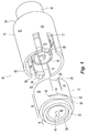
Fig. 1 is a perspective view of one embodiment of an electrical connector according to the present invention in an unmated position; -
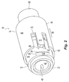
Fig. 2 is a perspective view of the electrical connector ofFig. 1 in a partially engaged position; -
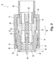
Fig. 3 is a cross sectional view of the electrical connector ofFig. 1 in a fully engaged position; -
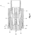
Fig. 4 is a cross sectional view of the electrical connector ofFig. 1 with the two bodies slightly rotated relative to one another; -
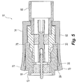
Fig. 5 is a cross sectional view of the electrical connector ofFig. 1 with the two bodies rotated relative to one another which allows the bodies to be separated with little force; -
Fig. 6 is a cross sectional view of another embodiment of a second connector body of an electrical connector according to the present invention; -
Fig. 7 is a cross sectional view of yet another embodiment of a second connector body of an electrical connector according to the present invention; and -
Fig. 8 is a schematic of a PCB board that can be used with the electrical connector. - Reference will now be made in detail to the present preferred embodiment(s) of the invention, examples of which are illustrated in the accompanying drawings. Whenever possible, the same reference numerals will be used throughout the drawings to refer to the same or like parts.
- Referring to
FIGS. 1 and2 , anelectrical connector 10 has afirst connector body 12 and asecond connector body 14. Thefirst connector body 12 has aforward portion 16 and arearward portion 18. Theforward portion 16 has afront end 20 and therearward portion 18 has aback end 22, with an opening 24 extending therebetween. Theforward portion 16 has a generally circular cross section with at least oneinclined surface 26 extending from thefront end 20 toward amiddle portion 28 of thefront portion 16. Theinclined surface 26 inclines toward theouter surface 30 offirst connector body 12 from thefront end 20. Theinclined surface 26 transitions into theouter surface 30, where there is a generallystraight portion 32 that creates aledge 34 between the generallystraight portion 32 andouter surface 30, that in turn is adjacent theinclined surface 26. As illustrated in the figures, there are preferably twoinclined surfaces 26, two generallystraight portions 32, and twoledges 34. However, only one, or more, may be present and still come within the scope of the invention. - The generally
straight portion 32 transitions into theouter surface 30 of thefirst connector body 12 attransition portions 36 at either end of the generallystraight portion 32. Thetransition portions 36 have a radius that is preferably different from the diameter of theouter surface 30 of thefirst connector body 12. Preferably, the radius of thetransition portion 36 is about 0.025 inches, but could range anywhere from 0.00 inches to 0.050 inches. The radius of thetransition portion 36 is important for the operation of theelectrical connector 10, as described in more detail below. It should also be noted that the radius and range of the radius can vary with size of the connector. - The
rearward portion 18 offirst connector body 12 also has a generally circular cross section and has a diameter that is generally smaller than that of theforward portion 16. However the diameter ofrearward portion 18 may also be the same as or larger than the radius of theforward portion 16. As is best illustrated inFig. 3 , thefirst connector body 12 may also have acenter contact 40 and adielectric member 42 to hold and center thecenter contact 40. Theback end 22 ofrearward portion 18 of thefirst connector body 12 and thecenter contact 40 are soldered to the PCB as is known in the art. For example as illustrated inFig. 8 , aPCB 90 is illustrated. The PCB 90 has anopening 92 into which thecenter contact 40 is soldered so that it makes contact with thesignal metallization 94 and theback end 22 is soldered to theground metallization 96. Themetallizations - The
electrical connector 10 also includes thesecond connector body 14.Second connector body 14 has anouter sleeve 60 with afront end 62 and aback end 64 and an opening 66 extending therebetween. Theouter sleeve 60 may be knurled or grooved to assist in gripping thesecond connector body 14. Thesecond connector body 14 has amiddle portion 68, where twocantilevered arms 70 extend toward thefront end 62. Thearms 70 are essentially a portion of the outer sleeve, as thearms 70 have the same outer diameter as the remainder of theouter sleeve 60 and are defined by twoslots 72 extending from thefront end 62 to themiddle portion 68. The opening 66 preferably has two portions, a frontinner portion 74 and a rearinner portion 76. SeeFig. 3 . The frontinner portion 74 has a first diameter that is larger than the second diameter of the rearinner portion 76, thereby creating a forward facingsurface 78 in themiddle portion 68. The rearinner portion 76 is configured to receive a cable adapter, center contact and dielectric 80. The cable adapter, center contact and dielectric 80 are standard parts, known to those of skill in the art. Thesecond connector body 14 is attached to a cable (not shown) and the cable adapter in a standard way. - The
arms 70 are, by their nature, flexible and are able to flex outward (away from the opening 66). Thearms 70 preferably have at the front end 82 a downward extending projections 84 (and, in particular, rearward facing surfaces 88) that engage theledge 34 of thefirst connector body 12. Preferably, thearms 70 also have a chamferedportion 86 on thefront end 82 to assist in guiding thearms 70 onto the at least oneinclined surface 26. As theforward portion 16 of firstconnector body portion 12 is inserted into theopening 66 of thesecond connector body 14, thearms 70 engage the inclined surface 26 (seeFig. 2 ) and are flexed outwardly. As the two connector bodies are moved relative to one another, thearms 70 are flexed further outward until the downward extendingprojections 84 go over theledge 34 and make contact with the generallystraight portion 32. The engagement of the downward extendingprojections 84 with theledge 34 prevents thesecond connector body 14 from being pulled axially away from thefirst connector body 12. - With the
ledge 34 and the rearward facingsurfaces 88 of downward extendingprojections 84 engaging one another, the twoconnector bodies second connector bodies connector bodies Fig. 3 , the twoconnector bodies Fig. 4 illustrates that the twoconnector bodies arms 70 rotate and move along the generallystraight portion 32, thearms 70 begin to flex outward. As thearms 70 approach thetransition portions 36, thearms 70 flex outwardly even more. The larger the radius of thetransition portions 36, the easier thearms 70 move from the generallystraight portion 32 to theouter surface 30. When thearms 70 make contact with theouter surface 30 that has a constant radius (seeFig. 5 ), thesecond connector body 14 can be moved axially relative to thefirst connector body 12 and unmated with little force (generally limited to the friction of the downward extendingprojections 84 on the first connector body 12). - An alternative embodiment of a
second connector body 114 is illustrated inFig. 6 . Thesecond connector body 114 is similar to thesecond connector body 14 discussed above, but has anelastomeric gasket 120 that engages theforward facing surface 178 in themiddle portion 168. Theelastomeric gasket 120 is preferably impregnated with metallic particles to assist in preventing leakage of the electrical signal from the connector. Theelastomeric gasket 120 allows the connector to be sealed against the elements when the first connector body is inserted into theopening 166 and the front end of the first connector body engages theelastomeric gasket 120 and compresses it against the forward facingsurface 178. - As illustrated in
FIGS. 3-5 above, theledge 34 and the rearward facingsurfaces 88 of downward extendingprojections 84 ofconnector 10 are illustrated as being perpendicular to its axial axis. However, it is possible that theledge 34 and the rearward facingsurfaces 88 of downward extendingprojections 84 are slanted in a rearward direction to allow for easier engagement of theledge 34 by the rearward facing surfaces of downward extendingprojections 84. For example, as illustrated inFig. 6 , rearward facingsurfaces 188 of downward extending projections 184 have an angle other than 90 degrees with the front inner portion 174 (theledge 34 would have a corresponding angle, but is not illustrated). Such a configuration compensates for any variations in the tolerances of the first and second connector bodies. - Another alternative embodiment of a
second connector body 214 is illustrated inFig. 7 . Thesecond connector body 214 has awave spring washer 220 also disposed against the forward facingsurface 278 in themiddle portion 268, where it further limits the axial movement of the connector bodies relative to one another. - It will be apparent to those skilled in the art that various modifications and variations can be made to the present invention without departing from the scope of the invention. Thus it is intended that the present invention cover the modifications and variations of this invention provided they come within the scope of the appended claims and their equivalents.
Claims (13)
- A connector (10) for a printed circuit board (90) comprising:a main body (12) having a forward portion (16) with an outer surface (30) and a rearward portion (18), a front end (20) and a back end (22) and an opening (24) extending therebetween, the front end (20) disposed on the forward portion (16) and the back end (22) disposed on the rearward portion (16); the forward portion (16) having a generally circular cross section;the forward portion (16) having at least one inclined surface (26) extending from the front end (20) to a middle portion (28) of the forward portion (16),characterized in that
the at least one inclined surface (26) inclines toward and transitions into the outer surface (30) between the front end (20) and the middle portion (28) of the forward portion (16); and in that
at least one generally straight portion (32) adjacent to where the inclined surface (26) transitions into the outer surface (30) creating a ledge (34) between where the inclined surface (26) transitions into the outer surface (30) and the straight portion (32), and wherein the straight portion (32) transitions to the outer surface (30) of the forward portion (16) of the main body (12) at transition portions (36). - The connector according to claim 1, wherein the forward portion (16) has an outer surface having a first outer diameter and the rearward portion (18) has an outer surface having a second diameter, the first diameter being different from the second diameter.
- The connector according to claim 1, wherein the generally straight portion (32) and the ledge (34) have an angle other than 90 degrees.
- The connector according to claim 1, wherein the transition portion (36) has a predetermined radius.
- The connector according to claim 1, wherein the rearward portion (18) is electrically connectable to printed circuit board trace connections.
- The connector according to claim 1, wherein the opening (24) is configured to receive a female cable connector.
- An electrical connector (10) for connecting a printed circuit board (90) and a coaxial cable comprising:a first connector body (12) having a forward portion (16) and a rearward portion (18), a front end (20) and a back end (22) and an opening (24) extending therebetween, the front end (20) disposed on the forward portion (16) and the back end (22) disposed on the rearward portion (18), the forward portion (16) having a generally circular cross section, the forward portion (16) having at least one inclined surface (26) extending from the front end (20) to a middle portion (28) of the forward portion, and at least one generally straight portion (32) adjacent the inclined surface (26) creating a ledge (34) between the inclined surface (26) and the straight portion (32); anda second connector body (14, 114, 214);characterized in that
the second connector body (14, 114, 214) has an outer sleeve (60), the sleeve (60) having a front end (62) and a back end (64) and an opening (66) therebetween, the opening (66) configured to receive at least a portion of the forward portion (16) of the first connector body (12), the outer sleeve (60) having a least one arm (70) extending between the front end (62) and a middle portion (68) and configured to engage the inclined portion (26) and ledge (34) of the forward portion (16) to prevent axial movement of the first and second connector bodies relative to one another when the first connector body (12) is disposed in the second connector body opening (66). - The electrical connector according to claim 7, wherein rotating the second connector body (14, 114, 214) relative to the first connector body (12) moves the at least one arm (70) from the at least one generally straight portion (32) and ledge (34) whereby the first and second connector bodies can be moved in an axial direction away from one another.
- The electrical connector according to claim 7, wherein the second connector body (14, 114, 214) has a forward facing surface (78) extending at least partially about the opening (55) and disposed between the front end (62) and the back end (64) and engages the front end (20) of the first connector body (12) when the first connector body (12) is fully inserted into the second connector body (14, 114, 214).
- The electrical connector according to claim 7, wherein the first connector body (12) includes a recessed portion circumferentially about the front end (20) and an elastic member disposed therein.
- The electrical connector according to claim 7, wherein the elastic member includes metallic particles to prevent signal leakage.
- The electrical connector according to claim 7, wherein the arm (70) includes a downward extending portion (4) to engage the ledge (34).
- The electrical connector according to claim 7, further comprising a spring wave washer (220) disposed between the first connector body and the second connector body.
Applications Claiming Priority (2)
| Application Number | Priority Date | Filing Date | Title |
|---|---|---|---|
| US12/433,302 US7914347B2 (en) | 2009-04-30 | 2009-04-30 | Low resistance connector for printed circuit board |
| PCT/US2010/032888 WO2010127065A1 (en) | 2009-04-30 | 2010-04-29 | Low resistance connector for printed circuit board |
Publications (2)
| Publication Number | Publication Date |
|---|---|
| EP2425496A1 EP2425496A1 (en) | 2012-03-07 |
| EP2425496B1 true EP2425496B1 (en) | 2016-07-27 |
Family
ID=42556932
Family Applications (1)
| Application Number | Title | Priority Date | Filing Date |
|---|---|---|---|
| EP10716719.9A Not-in-force EP2425496B1 (en) | 2009-04-30 | 2010-04-29 | Low resistance connector for printed circuit board |
Country Status (6)
| Country | Link |
|---|---|
| US (1) | US7914347B2 (en) |
| EP (1) | EP2425496B1 (en) |
| CN (1) | CN102498619B (en) |
| DK (1) | DK2425496T3 (en) |
| TW (1) | TWI533531B (en) |
| WO (1) | WO2010127065A1 (en) |
Families Citing this family (27)
| Publication number | Priority date | Publication date | Assignee | Title |
|---|---|---|---|---|
| FR2935202B1 (en) * | 2008-08-21 | 2010-10-22 | Labinal | DEVICE FOR CONNECTION BETWEEN AN ELECTRICAL CABLE AND A CONDUCTIVE STRUCTURE, IN PARTICULAR FOR A CURRENT RETURN CIRCUIT |
| CN201667478U (en) * | 2009-11-10 | 2010-12-08 | 富士康(昆山)电脑接插件有限公司 | Adapter |
| DE102009060423A1 (en) * | 2009-12-22 | 2011-07-21 | dspace digital signal processing and control engineering GmbH, 33102 | contacting |
| US8668504B2 (en) | 2011-07-05 | 2014-03-11 | Dave Smith Chevrolet Oldsmobile Pontiac Cadillac, Inc. | Threadless light bulb socket |
| WO2013015451A2 (en) * | 2011-07-25 | 2013-01-31 | Yazaki Corporation | Electrical connector |
| DE102011056466A1 (en) * | 2011-12-15 | 2013-06-20 | Telegärtner Karl Gärtner GmbH | Coaxial connector arrangement |
| US8845368B1 (en) * | 2012-08-31 | 2014-09-30 | Amazon Technologies, Inc. | Electrical connectors |
| JP5883366B2 (en) * | 2012-09-06 | 2016-03-15 | ヒロセ電機株式会社 | Electrical connector assembly |
| CN102842816B (en) * | 2012-09-28 | 2014-12-31 | 苏州瑞可达连接系统股份有限公司 | Radio frequency coaxial connecting mechanism |
| US8784130B2 (en) * | 2012-11-06 | 2014-07-22 | Solarcity Corporation | Supply side backfeed meter socket adapter |
| CN103280666B (en) * | 2013-04-27 | 2015-11-25 | 中航光电科技股份有限公司 | Underwater separation electric connector and plug thereof |
| DE102014101297B4 (en) * | 2014-02-03 | 2017-06-22 | Telegärtner Karl Gärtner GmbH | Coaxial connector arrangement |
| DE102014001546B4 (en) * | 2014-02-07 | 2017-02-16 | Wolfgang Kunzweiler | plug-in coupling |
| US9478929B2 (en) | 2014-06-23 | 2016-10-25 | Ken Smith | Light bulb receptacles and light bulb sockets |
| JP6074753B2 (en) * | 2014-11-25 | 2017-02-08 | ヒロセ電機株式会社 | Electrical connector assembly |
| CN106560957B (en) * | 2015-10-06 | 2020-04-24 | 富士康(昆山)电脑接插件有限公司 | Power connector adapter and assembling method thereof |
| JP6319280B2 (en) | 2015-12-09 | 2018-05-09 | 第一精工株式会社 | Connector device |
| USD843320S1 (en) | 2016-08-26 | 2019-03-19 | HARTING Electronics GmbH | Electrical plug connector |
| US10756521B2 (en) * | 2016-09-20 | 2020-08-25 | Nite Ize, Inc. | Cord sleeve device and installation tool and method for use |
| JP6811654B2 (en) * | 2017-03-14 | 2021-01-13 | 日立オートモティブシステムズ株式会社 | connector |
| KR101921128B1 (en) * | 2018-04-27 | 2018-11-22 | 주식회사 엠피디 | Receptacle connector |
| CN111740272B (en) * | 2019-03-25 | 2021-11-26 | 珠海保税区光联通讯技术有限公司 | Connector with a locking member |
| DE102019117473A1 (en) * | 2019-06-28 | 2020-12-31 | Tesat-Spacecom Gmbh & Co. Kg | Circuit arrangement consisting of two interconnected high-frequency components |
| CN112366474B (en) * | 2020-10-31 | 2021-12-03 | 贵州电网有限责任公司 | Series-parallel hybrid power supply direct-current power supply system |
| JP7679247B2 (en) * | 2021-07-15 | 2025-05-19 | リズム株式会社 | Circuit board connection terminals |
| US20230133043A1 (en) * | 2021-11-02 | 2023-05-04 | Comtest Networks Inc. | Bnc with intergrated switch |
| CN121097424A (en) * | 2025-11-12 | 2025-12-09 | 中航光电科技股份有限公司 | Inter-board floating connector |
Family Cites Families (24)
| Publication number | Priority date | Publication date | Assignee | Title |
|---|---|---|---|---|
| US3546658A (en) * | 1968-04-22 | 1970-12-08 | United Carr Inc | Connector with splined backshell |
| US4211461A (en) * | 1978-11-27 | 1980-07-08 | Industrial Electronic Hardware Corp. | Axially mating cable connector |
| JPS601503Y2 (en) * | 1979-03-16 | 1985-01-16 | アルプス電気株式会社 | connector |
| US5688254A (en) * | 1983-01-24 | 1997-11-18 | Icu Medical, Inc. | Medical connector |
| JPS62285378A (en) * | 1986-06-04 | 1987-12-11 | ヒロセ電機株式会社 | Female coaxial connector and manufacture thereof |
| US4932673A (en) * | 1988-02-01 | 1990-06-12 | Hughes Aircraft Company | Emi suppression gasket for millimeter waveguides |
| US4881912A (en) * | 1988-04-29 | 1989-11-21 | Specialty Connector Company, Inc. | High voltage coaxial connector |
| DE29517358U1 (en) * | 1995-11-02 | 1996-01-11 | Harting Elektronik Gmbh, 32339 Espelkamp | Coaxial connector |
| US6164977A (en) * | 1998-02-09 | 2000-12-26 | Itt Manufacturing Enterprises, Inc. | Standoff board-mounted coaxial connector |
| US5993239A (en) * | 1998-07-08 | 1999-11-30 | Osram Sylvania Inc. | Positive latch connector |
| US6062607A (en) * | 1998-07-17 | 2000-05-16 | Proprietary Technology, Inc. | Quick connector with secondary latch confirming feature |
| US6450829B1 (en) * | 2000-12-15 | 2002-09-17 | Tyco Electronics Canada, Ltd. | Snap-on plug coaxial connector |
| US6409534B1 (en) * | 2001-01-08 | 2002-06-25 | Tyco Electronics Canada Ltd. | Coax cable connector assembly with latching housing |
| US6361348B1 (en) * | 2001-01-15 | 2002-03-26 | Tyco Electronics Corporation | Right angle, snap on coaxial electrical connector |
| USD456355S1 (en) * | 2001-03-02 | 2002-04-30 | Smk Corporation | Coaxial connector |
| TW545726U (en) * | 2002-09-25 | 2003-08-01 | Hon Hai Prec Ind Co Ltd | Electrical connector |
| TW562291U (en) * | 2002-12-04 | 2003-11-11 | Hon Hai Prec Ind Co Ltd | Radio frequency connector assembly |
| US7029286B2 (en) * | 2003-02-07 | 2006-04-18 | Tyco Electronics Corporation | Plastic housings for jack assemblies |
| US6955563B1 (en) * | 2005-02-08 | 2005-10-18 | Croan Quinn F | RJ type modular connector for coaxial cables |
| US7234956B2 (en) * | 2005-09-02 | 2007-06-26 | Kauffman George M | Electrical connector with dual independent coupling means |
| CN2847596Y (en) * | 2005-11-04 | 2006-12-13 | 西安科耐特科技有限责任公司 | Quick insert self locking radio frequency coaxial connector |
| US20070249236A1 (en) * | 2006-04-20 | 2007-10-25 | Randy Petak | System for ensuring electrical continuity in connection between pre-wired electrical harnesses and conduits |
| US7335058B1 (en) * | 2006-12-13 | 2008-02-26 | Corning Gilbert, Inc. | Snap-fit connector assembly |
| KR100818644B1 (en) * | 2007-01-31 | 2008-04-02 | 삼성전자주식회사 | Actuator latches on hard disk drives and their hard disk drives |
-
2009
- 2009-04-30 US US12/433,302 patent/US7914347B2/en active Active
-
2010
- 2010-04-28 TW TW099113594A patent/TWI533531B/en not_active IP Right Cessation
- 2010-04-29 DK DK10716719.9T patent/DK2425496T3/en active
- 2010-04-29 CN CN201080027462.2A patent/CN102498619B/en not_active Expired - Fee Related
- 2010-04-29 EP EP10716719.9A patent/EP2425496B1/en not_active Not-in-force
- 2010-04-29 WO PCT/US2010/032888 patent/WO2010127065A1/en not_active Ceased
Also Published As
| Publication number | Publication date |
|---|---|
| TWI533531B (en) | 2016-05-11 |
| CN102498619A (en) | 2012-06-13 |
| TW201112523A (en) | 2011-04-01 |
| WO2010127065A1 (en) | 2010-11-04 |
| US7914347B2 (en) | 2011-03-29 |
| EP2425496A1 (en) | 2012-03-07 |
| CN102498619B (en) | 2015-01-28 |
| DK2425496T3 (en) | 2016-11-14 |
| US20100279536A1 (en) | 2010-11-04 |
Similar Documents
| Publication | Publication Date | Title |
|---|---|---|
| EP2425496B1 (en) | Low resistance connector for printed circuit board | |
| US20100304579A1 (en) | Low Resistance Connector For Printed Circuit Board | |
| US7758370B1 (en) | Quick release electrical connector | |
| EP1854182B1 (en) | Gimbling electronic connector | |
| EP2304847B1 (en) | Snap-on coaxial cable connector | |
| US8628359B2 (en) | Connector and connector unit | |
| US8512073B2 (en) | Coaxial electric connector | |
| US8992250B1 (en) | Clockable cable adapter | |
| EP2625749B1 (en) | A connector system | |
| EP3066726B1 (en) | Float plate for blind matable electrical cable connectors | |
| US20130203288A1 (en) | Coaxial angled adapter | |
| CN112787120A (en) | Coaxial connector and board-to-board connector assembly | |
| WO2012116179A2 (en) | Lockable mating connector | |
| US20130157505A1 (en) | Coaxial connector | |
| WO2019046517A1 (en) | Coaxial cable connector with grounding coupling nut | |
| US20180316103A1 (en) | Multi-pin connector block assembly | |
| US10707621B2 (en) | Connector device and coaxial connector | |
| US8206189B2 (en) | Inner terminal | |
| US12525750B2 (en) | Round plug connector comprising a shield connection | |
| CN210489873U (en) | Coaxial connector and board-to-board connector assembly | |
| US20180375258A1 (en) | Self-aligning cable mating connector | |
| EP3616267B1 (en) | Radio frequency (rf) connector pin assembly | |
| JP6045307B2 (en) | Coaxial connector | |
| CN223828785U (en) | Coaxial connector and connector assembly | |
| US20070228839A1 (en) | Connector |
Legal Events
| Date | Code | Title | Description |
|---|---|---|---|
| PUAI | Public reference made under article 153(3) epc to a published international application that has entered the european phase |
Free format text: ORIGINAL CODE: 0009012 |
|
| 17P | Request for examination filed |
Effective date: 20111027 |
|
| AK | Designated contracting states |
Kind code of ref document: A1 Designated state(s): AT BE BG CH CY CZ DE DK EE ES FI FR GB GR HR HU IE IS IT LI LT LU LV MC MK MT NL NO PL PT RO SE SI SK SM TR |
|
| DAX | Request for extension of the european patent (deleted) | ||
| GRAP | Despatch of communication of intention to grant a patent |
Free format text: ORIGINAL CODE: EPIDOSNIGR1 |
|
| RIC1 | Information provided on ipc code assigned before grant |
Ipc: H01R 13/627 20060101AFI20150511BHEP Ipc: H01R 13/646 20110101ALI20150511BHEP Ipc: H01R 24/50 20110101ALI20150511BHEP Ipc: H01R 13/625 20060101ALI20150511BHEP Ipc: H01R 103/00 20060101ALI20150511BHEP Ipc: H01R 13/635 20060101ALI20150511BHEP |
|
| INTG | Intention to grant announced |
Effective date: 20150617 |
|
| GRAS | Grant fee paid |
Free format text: ORIGINAL CODE: EPIDOSNIGR3 |
|
| INTG | Intention to grant announced |
Effective date: 20160107 |
|
| GRAA | (expected) grant |
Free format text: ORIGINAL CODE: 0009210 |
|
| AK | Designated contracting states |
Kind code of ref document: B1 Designated state(s): AT BE BG CH CY CZ DE DK EE ES FI FR GB GR HR HU IE IS IT LI LT LU LV MC MK MT NL NO PL PT RO SE SI SK SM TR |
|
| REG | Reference to a national code |
Ref country code: GB Ref legal event code: FG4D |
|
| REG | Reference to a national code |
Ref country code: CH Ref legal event code: EP |
|
| REG | Reference to a national code |
Ref country code: AT Ref legal event code: REF Ref document number: 816472 Country of ref document: AT Kind code of ref document: T Effective date: 20160815 |
|
| REG | Reference to a national code |
Ref country code: IE Ref legal event code: FG4D |
|
| REG | Reference to a national code |
Ref country code: DE Ref legal event code: R096 Ref document number: 602010035028 Country of ref document: DE |
|
| REG | Reference to a national code |
Ref country code: NL Ref legal event code: FP |
|
| REG | Reference to a national code |
Ref country code: DK Ref legal event code: T3 Effective date: 20161111 |
|
| REG | Reference to a national code |
Ref country code: LT Ref legal event code: MG4D |
|
| REG | Reference to a national code |
Ref country code: AT Ref legal event code: MK05 Ref document number: 816472 Country of ref document: AT Kind code of ref document: T Effective date: 20160727 |
|
| PG25 | Lapsed in a contracting state [announced via postgrant information from national office to epo] |
Ref country code: IS Free format text: LAPSE BECAUSE OF FAILURE TO SUBMIT A TRANSLATION OF THE DESCRIPTION OR TO PAY THE FEE WITHIN THE PRESCRIBED TIME-LIMIT Effective date: 20161127 Ref country code: IT Free format text: LAPSE BECAUSE OF FAILURE TO SUBMIT A TRANSLATION OF THE DESCRIPTION OR TO PAY THE FEE WITHIN THE PRESCRIBED TIME-LIMIT Effective date: 20160727 Ref country code: HR Free format text: LAPSE BECAUSE OF FAILURE TO SUBMIT A TRANSLATION OF THE DESCRIPTION OR TO PAY THE FEE WITHIN THE PRESCRIBED TIME-LIMIT Effective date: 20160727 Ref country code: LT Free format text: LAPSE BECAUSE OF FAILURE TO SUBMIT A TRANSLATION OF THE DESCRIPTION OR TO PAY THE FEE WITHIN THE PRESCRIBED TIME-LIMIT Effective date: 20160727 Ref country code: NO Free format text: LAPSE BECAUSE OF FAILURE TO SUBMIT A TRANSLATION OF THE DESCRIPTION OR TO PAY THE FEE WITHIN THE PRESCRIBED TIME-LIMIT Effective date: 20161027 Ref country code: FI Free format text: LAPSE BECAUSE OF FAILURE TO SUBMIT A TRANSLATION OF THE DESCRIPTION OR TO PAY THE FEE WITHIN THE PRESCRIBED TIME-LIMIT Effective date: 20160727 |
|
| PG25 | Lapsed in a contracting state [announced via postgrant information from national office to epo] |
Ref country code: SE Free format text: LAPSE BECAUSE OF FAILURE TO SUBMIT A TRANSLATION OF THE DESCRIPTION OR TO PAY THE FEE WITHIN THE PRESCRIBED TIME-LIMIT Effective date: 20160727 Ref country code: ES Free format text: LAPSE BECAUSE OF FAILURE TO SUBMIT A TRANSLATION OF THE DESCRIPTION OR TO PAY THE FEE WITHIN THE PRESCRIBED TIME-LIMIT Effective date: 20160727 Ref country code: PL Free format text: LAPSE BECAUSE OF FAILURE TO SUBMIT A TRANSLATION OF THE DESCRIPTION OR TO PAY THE FEE WITHIN THE PRESCRIBED TIME-LIMIT Effective date: 20160727 Ref country code: LV Free format text: LAPSE BECAUSE OF FAILURE TO SUBMIT A TRANSLATION OF THE DESCRIPTION OR TO PAY THE FEE WITHIN THE PRESCRIBED TIME-LIMIT Effective date: 20160727 Ref country code: PT Free format text: LAPSE BECAUSE OF FAILURE TO SUBMIT A TRANSLATION OF THE DESCRIPTION OR TO PAY THE FEE WITHIN THE PRESCRIBED TIME-LIMIT Effective date: 20161128 Ref country code: GR Free format text: LAPSE BECAUSE OF FAILURE TO SUBMIT A TRANSLATION OF THE DESCRIPTION OR TO PAY THE FEE WITHIN THE PRESCRIBED TIME-LIMIT Effective date: 20161028 Ref country code: BE Free format text: LAPSE BECAUSE OF FAILURE TO SUBMIT A TRANSLATION OF THE DESCRIPTION OR TO PAY THE FEE WITHIN THE PRESCRIBED TIME-LIMIT Effective date: 20160727 Ref country code: AT Free format text: LAPSE BECAUSE OF FAILURE TO SUBMIT A TRANSLATION OF THE DESCRIPTION OR TO PAY THE FEE WITHIN THE PRESCRIBED TIME-LIMIT Effective date: 20160727 |
|
| PG25 | Lapsed in a contracting state [announced via postgrant information from national office to epo] |
Ref country code: RO Free format text: LAPSE BECAUSE OF FAILURE TO SUBMIT A TRANSLATION OF THE DESCRIPTION OR TO PAY THE FEE WITHIN THE PRESCRIBED TIME-LIMIT Effective date: 20160727 Ref country code: EE Free format text: LAPSE BECAUSE OF FAILURE TO SUBMIT A TRANSLATION OF THE DESCRIPTION OR TO PAY THE FEE WITHIN THE PRESCRIBED TIME-LIMIT Effective date: 20160727 |
|
| REG | Reference to a national code |
Ref country code: DE Ref legal event code: R097 Ref document number: 602010035028 Country of ref document: DE |
|
| PG25 | Lapsed in a contracting state [announced via postgrant information from national office to epo] |
Ref country code: SM Free format text: LAPSE BECAUSE OF FAILURE TO SUBMIT A TRANSLATION OF THE DESCRIPTION OR TO PAY THE FEE WITHIN THE PRESCRIBED TIME-LIMIT Effective date: 20160727 Ref country code: SK Free format text: LAPSE BECAUSE OF FAILURE TO SUBMIT A TRANSLATION OF THE DESCRIPTION OR TO PAY THE FEE WITHIN THE PRESCRIBED TIME-LIMIT Effective date: 20160727 Ref country code: BG Free format text: LAPSE BECAUSE OF FAILURE TO SUBMIT A TRANSLATION OF THE DESCRIPTION OR TO PAY THE FEE WITHIN THE PRESCRIBED TIME-LIMIT Effective date: 20161027 Ref country code: CZ Free format text: LAPSE BECAUSE OF FAILURE TO SUBMIT A TRANSLATION OF THE DESCRIPTION OR TO PAY THE FEE WITHIN THE PRESCRIBED TIME-LIMIT Effective date: 20160727 |
|
| PLBE | No opposition filed within time limit |
Free format text: ORIGINAL CODE: 0009261 |
|
| STAA | Information on the status of an ep patent application or granted ep patent |
Free format text: STATUS: NO OPPOSITION FILED WITHIN TIME LIMIT |
|
| 26N | No opposition filed |
Effective date: 20170502 |
|
| PG25 | Lapsed in a contracting state [announced via postgrant information from national office to epo] |
Ref country code: SI Free format text: LAPSE BECAUSE OF FAILURE TO SUBMIT A TRANSLATION OF THE DESCRIPTION OR TO PAY THE FEE WITHIN THE PRESCRIBED TIME-LIMIT Effective date: 20160727 |
|
| REG | Reference to a national code |
Ref country code: CH Ref legal event code: PL |
|
| REG | Reference to a national code |
Ref country code: IE Ref legal event code: MM4A |
|
| REG | Reference to a national code |
Ref country code: FR Ref legal event code: ST Effective date: 20171229 |
|
| PG25 | Lapsed in a contracting state [announced via postgrant information from national office to epo] |
Ref country code: FR Free format text: LAPSE BECAUSE OF NON-PAYMENT OF DUE FEES Effective date: 20170502 Ref country code: MC Free format text: LAPSE BECAUSE OF FAILURE TO SUBMIT A TRANSLATION OF THE DESCRIPTION OR TO PAY THE FEE WITHIN THE PRESCRIBED TIME-LIMIT Effective date: 20160727 |
|
| PG25 | Lapsed in a contracting state [announced via postgrant information from national office to epo] |
Ref country code: LI Free format text: LAPSE BECAUSE OF NON-PAYMENT OF DUE FEES Effective date: 20170430 Ref country code: LU Free format text: LAPSE BECAUSE OF NON-PAYMENT OF DUE FEES Effective date: 20170429 Ref country code: CH Free format text: LAPSE BECAUSE OF NON-PAYMENT OF DUE FEES Effective date: 20170430 |
|
| PG25 | Lapsed in a contracting state [announced via postgrant information from national office to epo] |
Ref country code: IE Free format text: LAPSE BECAUSE OF NON-PAYMENT OF DUE FEES Effective date: 20170429 |
|
| PG25 | Lapsed in a contracting state [announced via postgrant information from national office to epo] |
Ref country code: MT Free format text: LAPSE BECAUSE OF NON-PAYMENT OF DUE FEES Effective date: 20170429 |
|
| PG25 | Lapsed in a contracting state [announced via postgrant information from national office to epo] |
Ref country code: HU Free format text: LAPSE BECAUSE OF FAILURE TO SUBMIT A TRANSLATION OF THE DESCRIPTION OR TO PAY THE FEE WITHIN THE PRESCRIBED TIME-LIMIT; INVALID AB INITIO Effective date: 20100429 |
|
| PG25 | Lapsed in a contracting state [announced via postgrant information from national office to epo] |
Ref country code: CY Free format text: LAPSE BECAUSE OF NON-PAYMENT OF DUE FEES Effective date: 20160727 |
|
| PG25 | Lapsed in a contracting state [announced via postgrant information from national office to epo] |
Ref country code: MK Free format text: LAPSE BECAUSE OF FAILURE TO SUBMIT A TRANSLATION OF THE DESCRIPTION OR TO PAY THE FEE WITHIN THE PRESCRIBED TIME-LIMIT Effective date: 20160727 |
|
| PG25 | Lapsed in a contracting state [announced via postgrant information from national office to epo] |
Ref country code: TR Free format text: LAPSE BECAUSE OF FAILURE TO SUBMIT A TRANSLATION OF THE DESCRIPTION OR TO PAY THE FEE WITHIN THE PRESCRIBED TIME-LIMIT Effective date: 20160727 |
|
| PGFP | Annual fee paid to national office [announced via postgrant information from national office to epo] |
Ref country code: DK Payment date: 20210326 Year of fee payment: 12 |
|
| REG | Reference to a national code |
Ref country code: DK Ref legal event code: EBP Effective date: 20220430 |
|
| PG25 | Lapsed in a contracting state [announced via postgrant information from national office to epo] |
Ref country code: DK Free format text: LAPSE BECAUSE OF NON-PAYMENT OF DUE FEES Effective date: 20220430 |
|
| PGFP | Annual fee paid to national office [announced via postgrant information from national office to epo] |
Ref country code: GB Payment date: 20230315 Year of fee payment: 14 |
|
| PGFP | Annual fee paid to national office [announced via postgrant information from national office to epo] |
Ref country code: NL Payment date: 20230323 Year of fee payment: 14 |
|
| PGFP | Annual fee paid to national office [announced via postgrant information from national office to epo] |
Ref country code: DE Payment date: 20230320 Year of fee payment: 14 |
|
| REG | Reference to a national code |
Ref country code: DE Ref legal event code: R119 Ref document number: 602010035028 Country of ref document: DE |
|
| REG | Reference to a national code |
Ref country code: NL Ref legal event code: MM Effective date: 20240501 |
|
| GBPC | Gb: european patent ceased through non-payment of renewal fee |
Effective date: 20240429 |
|
| PG25 | Lapsed in a contracting state [announced via postgrant information from national office to epo] |
Ref country code: DE Free format text: LAPSE BECAUSE OF NON-PAYMENT OF DUE FEES Effective date: 20241105 |
|
| PG25 | Lapsed in a contracting state [announced via postgrant information from national office to epo] |
Ref country code: NL Free format text: LAPSE BECAUSE OF NON-PAYMENT OF DUE FEES Effective date: 20240501 |
|
| PG25 | Lapsed in a contracting state [announced via postgrant information from national office to epo] |
Ref country code: GB Free format text: LAPSE BECAUSE OF NON-PAYMENT OF DUE FEES Effective date: 20240429 |
|
| PG25 | Lapsed in a contracting state [announced via postgrant information from national office to epo] |
Ref country code: NL Free format text: LAPSE BECAUSE OF NON-PAYMENT OF DUE FEES Effective date: 20240501 Ref country code: GB Free format text: LAPSE BECAUSE OF NON-PAYMENT OF DUE FEES Effective date: 20240429 Ref country code: DE Free format text: LAPSE BECAUSE OF NON-PAYMENT OF DUE FEES Effective date: 20241105 |