EP2425375B1 - Vorrichtung zur identifizierung einer person mittels seine fingerabdrück - Google Patents
Vorrichtung zur identifizierung einer person mittels seine fingerabdrück Download PDFInfo
- Publication number
- EP2425375B1 EP2425375B1 EP10714887.6A EP10714887A EP2425375B1 EP 2425375 B1 EP2425375 B1 EP 2425375B1 EP 10714887 A EP10714887 A EP 10714887A EP 2425375 B1 EP2425375 B1 EP 2425375B1
- Authority
- EP
- European Patent Office
- Prior art keywords
- image
- template
- test chart
- identification
- Prior art date
- Legal status (The legal status is an assumption and is not a legal conclusion. Google has not performed a legal analysis and makes no representation as to the accuracy of the status listed.)
- Active
Links
Images
Classifications
-
- G—PHYSICS
- G06—COMPUTING OR CALCULATING; COUNTING
- G06V—IMAGE OR VIDEO RECOGNITION OR UNDERSTANDING
- G06V10/00—Arrangements for image or video recognition or understanding
- G06V10/40—Extraction of image or video features
-
- G—PHYSICS
- G06—COMPUTING OR CALCULATING; COUNTING
- G06V—IMAGE OR VIDEO RECOGNITION OR UNDERSTANDING
- G06V40/00—Recognition of biometric, human-related or animal-related patterns in image or video data
- G06V40/10—Human or animal bodies, e.g. vehicle occupants or pedestrians; Body parts, e.g. hands
- G06V40/12—Fingerprints or palmprints
- G06V40/13—Sensors therefor
- G06V40/1318—Sensors therefor using electro-optical elements or layers, e.g. electroluminescent sensing
-
- G—PHYSICS
- G06—COMPUTING OR CALCULATING; COUNTING
- G06V—IMAGE OR VIDEO RECOGNITION OR UNDERSTANDING
- G06V10/00—Arrangements for image or video recognition or understanding
- G06V10/10—Image acquisition
Definitions
- the present invention relates to a device for identifying or authenticating a person by his fingerprint, and a method of identification or authentication implemented by such an identification or authentication device. It finds application in the field of biometric recognition and in particular in the field of identification or authentication by fingerprint or palm analysis of a person.
- Biometric recognition is used to secure facilities such as buildings or machinery or to obtain the issuance of rights, such as the issuance of an identity card, the payment of a pension ...
- This technology allows to get rid of access codes or cards that may be stolen or falsified, or may authenticate the holder of these cards or the holder of the codes.
- the use of this technology makes it possible to reinforce security since the probability that two people will have two identical biometrics is practically nil.
- the search step of the reference template can consist of a recovery of the template stored on a card, or a template found in a database from a code.
- an identification method is implemented using an identification device which comprises a plurality of sensors of the CCD or camera type, associated a plurality of illumination means and processing means which from the images captured by the different sensors, implement the comparison step, the measurement step and the decision-making step.
- An identification based on a 3D capture provides better results than an identification based on two-dimensional (2D) capture.
- Such a mode of operation is a disadvantage because it is often difficult for a person to keep his hand sufficiently immobile during the capture step.
- an identification device In the context of a two-dimensional (2D) capture of the fingerprint, an identification device comprises a transparent rigid plate, illumination means, a sensor and processing means. The illumination means and the sensor are arranged behind the plate on which the person comes to press his finger. The image thus captured is then processed by the processing means.
- the use of such an identification device causes the crush of the finger when it bears against the rigid plate and, therefore, the deformation of the impression.
- Most often these systems only give a faithful image of the impression for the part of the finger (or the palm) in contact with the plate, but according to the pressing force on the plate or other factors physical, the impression can be more or less deformed and the image area more or less large resulting in uncertain identification. Such a capture is said to be without contact. Especially for the palm, it is impossible to make an acquisition of the whole surface in a comfortable way by crushing the hand on a plate.
- a three-dimensional capture of the fingerprint makes it possible to increase the analysis area and thus the number of information relating to the impression while reducing the deformations with respect to a two-dimensional contact capture.
- An object of the present invention is to propose a device for identifying or authenticating a person by his fingerprint and an identification or authentication method associated with the corresponding device which does not have the drawbacks of the state of the technique and which, in particular, allows capture of a large area of the footprint while maintaining the ease of use of sensors with contact.
- the support means comprise a rigid frame secured to the bottom and forming with the latter a receptacle in which the transparent block is constrained.
- test pattern is transparent for certain wavelengths and opaque for others.
- the surface of the transparent block having the pattern is preformed according to the type of imprint that can be identified.
- the transparent block is of the silicone envelope type containing silicone gel or a liquid.
- the line of sight of the capture means is orthogonal to the bottom.
- the line of sight of the capture means forms with the normal at the bottom an angle greater than the total reflection limit angle of the transparent block.
- the means for constructing the template of the imprint comprise means for calculating a geometric transformation of the deformed pattern into the undeformed pattern, geometric transformation means provided for applying said geometric transformation thus calculated. to the captured image of the imprint, and means for generating a template from the image thus transformed of the imprint.
- the means for constructing the imprint template include means for approximating the three-dimensional surface of the pattern, means for applying the captured image of the imprint on the three-dimensional surface. thus approximated, and means for generating a template from the image thus transformed of the imprint.
- the step of constructing the template of the imprint comprises a step of calculating a geometrical transformation of the deformed pattern into the undeformed pattern, a step of applying said transformation. geometrically calculated to the captured image of the footprint, and a step of generating a template from the image and transformed the footprint.
- the step of constructing the template of the imprint comprises a step of approximating the three-dimensional surface of the pattern, a step of applying the captured image of the imprint on the surface three-dimensional thus approximated, and a step of generating a template from the image thus transformed of the imprint.
- identification that is for the device or for the process.
- the difference between identification and authentication lies in the processing of the generated template which is compared to a set of reference templates of a database in the case of identification and which is compared to a reference template in the case of authentication, reference template that is obtained from a badge or a code, for example.
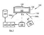
- the surface of the transparent block 102 on which the part of the body bearing the impression is pressed constitutes the acquisition surface.
- the verification means 114 are replaced by authentication means 114 of the person from the template thus constructed.
- the capture means 106, 126 is disposed downstream of the support means 102, 130.
- the verification step 214 is replaced by an authentication step 214 of the person from the template thus constructed.
- Such an identification device 100 thus allows a capture of an image of the fingerprint to be identified and its transformation into a template, the fingerprint being held in position during the capture of the image thanks to the presence of the transparent transparent block 102. Indeed, the hand or the finger is pressed on the transparent block 102 during the support step 202 and is maintained there. The movements of the hand of the person are thus avoided and the captured images are of good quality while allowing to generate and compare templates of the fingerprint to identify.
- the transparent block 102 is of the silicone envelope type containing silicone gel or a liquid.
- the materials constituting the support means 102, 130 must be optically compatible with an image capture through the bottom 130 and the transparent block 102. These materials must be highly transparent and non-diffusing.
- the bottom 130 is for example transparent plastic (PMMA, PC) or glass.
- the transparent block 102 deforms and matches the shape of the imprint, when under the pressure forces of the finger or the hand, the transparent block 102 matches the shape of the finger, respectively of the hand whose imprint must to be identified.
- the surface of the transparent block 102 on which the impression bears is chosen so as to promote optical coupling with the skin.
- the material constituting the surface of the transparent block 102 must therefore be sufficiently flexible to limit the presence of an air film between the skin and the transparent block 102.
- the silicone is a particularly well suited material.
- the pressure exerted by the finger or the hand must allow the crushing of the transparent block 102 without the skin of the finger or the hand is crushed excessively as in the case of the state of the art.
- the depression of the hand is of the order of 1 cm.
- the depression of the finger is of the order of 0.4 cm.
- the capture means 106, 126 which is implemented during the capture step 206, is preferably of the camera type whose axis of view respectively X, X 'is oriented towards the bottom 130 so as to see imprint to be transparently identified through the bottom 130, the transparent block 102 and the target 132.
- illumination means 104a and 104b in the form of lighting lamps are disposed on either side of the line of sight of the camera 106, 126 artwork.
- the illumination means 104a and 104b can be combined in different ways with the capture means 106, 126.
- the axis X of the capture means 106 may be orthogonal to the acquisition surface which is here parallel to the bottom 130 and the axis of each illumination means 104a, 104b can form with the surface of acquisition, an angle less than the total reflection limit angle of the transparent block 102.
- the axis X of the capture means 106 may be orthogonal to the acquisition surface which is here parallel to the bottom 130 and the axis of each illumination means 104a, 104b may form with the normal to the acquisition surface, an angle greater than the total reflection limit angle of the transparent block 102. The illumination is then in total reflection on the acquisition surface of the transparent block 102 when there is no contact with a finger.
- the axis X of the capture means 106 can form with the normal to the acquisition surface which is here parallel to the bottom 130 an angle greater than the total reflection limit angle of the transparent block 102, and the axis of the illumination means 104a, 104b is orthogonal to the acquisition surface which is here parallel to the bottom 130.
- the illumination is then in total reflection on the acquisition surface of the transparent block 102 when there do not touch with a finger.
- the axis X of the capture means 106 can form with the normal to the acquisition surface which is here parallel to the bottom 130 an angle greater than the total reflection limit angle of the transparent block 102, and the axis of the illumination means 104a, 104b also forms with the normal to the acquisition surface which is here parallel to the bottom 130 an angle greater than the total reflection limit angle of the transparent block 102.
- the axis X of the means capture 106 and the axis of the illumination means 104a, 104b are then substantially symmetrical with respect to the normal to the acquisition surface (ombroscopy total reflection imaging case).
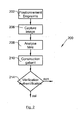
- the analysis means 108 analyze the image of the target 132 as it appears deformed on the captured image.
- the construction means 110 reconstruct a template of the imprint from the image of the captured imprint and the image of the pattern 132 thus analyzed by extraction of points interests of the image of the imprint.
- the step 210 of constructing the imprint template comprises a step of calculating a geometric transformation of the deformed pattern 132 into the undeformed pattern 132, a step of applying said geometric transformation thus calculated to the captured image of the imprint, and a step of generating a template from the image thus transformed of the imprint.
- the construction means 110 of the impression template include means for calculating a geometric transformation of the deformed pattern 132 into the undeformed pattern 132, geometric transformation means provided for applying said geometric transformation thus calculated. to the captured image of the imprint, and means for generating a template from the image thus transformed of the imprint.
- the calculation means generate a geometric transformation function that allows the image of the deformed target 132 to be straightened into a target image. 132 undistorted.
- the geometric transformation function is then applied to the image of the captured fingerprint to straighten it. After that, the template can be generated.
- this geometric transformation can be a homography.
- the pattern 132 is represented in the form of a grid consisting of cells
- a homography making it possible to pass from each cell of the deformed grid to a right cell and to the desired resolution is calculated and to estimate the Deformed cells are thus placed into a three-dimensional approximation of the surface by plane facets (piecemeal approximation).
- Another method relies on the use of a three-dimensional model such as a cylinder whose diameter is adapted according to the finger and the observed deformation. Once the known characteristics of the model, one applies the inverse transformation to unfold the footprint
- the size of the cells is substantially greater than the frequency of the peaks so as not to pose a problem of detection of one of these two pieces of information.
- the cells will be at least 3 mm apart.
- the step of constructing the template of the imprint comprises a step of approximating the three-dimensional surface of the pattern 132, a step of applying the captured image of the imprint on the surface three-dimensional thus approximated, and a step of generating a template from the image thus transformed of the imprint.
- the construction means 110 of the template of the imprint comprise means for approximating the three-dimensional surface of the pattern 132, means for applying the captured image of the imprint on the three-dimensional surface thus approximated. , and means for generating a template from the image thus transformed of the imprint.
- the approximation means determine the three-dimensional surface of the part of the body bearing the imprint.
- the application means apply on this surface the image of the captured impression, so as to copy the image of the imprint captured on the approximated surface. After that, the template can be generated.
- a step of straightening the image of the imprint applied to the three-dimensional surface can be performed prior to the step of generating the template.
- the pattern of the pattern 132 is known from the analysis means 108 and construction 110. It may be, for example, two sets of intersecting straight lines forming a grid, these lines being the finest possible to limit the degradation of the line. image of the impression while remaining sufficiently visible to be analyzed.
- the pattern 132 is transparent for certain wavelengths and opaque for others, so the imprint is visible through the lines, which can then be wider.
- the identification 214 and authentication 214 steps implement similar processes.
- Information such as the local curvature of the finger and the orientation of the fingerprint resulting naturally from the acquisition mode enrich the biometric representation of the fingerprint.
- the support means also comprise a rigid frame 128 secured to the bottom 130 and forming with the latter a receptacle in which the transparent block 102 is forced.
- the frame 128 is monoblock with the bottom 130 and is made of the same material. The expansion of the transparent block 102 under the effect of the pressure of the finger or hand is then performed only by vertical expansion outside the support zones. The target 132 then deforms almost only vertically and very little horizontally, thus facilitating the analysis of its image.
- the target 132 is translucent, thereby revealing by transparency the fingerprint to be identified.
- the pattern 132 is made in a different color from that of the imprint to be identified. So a filtering the image captured by color will eliminate the pattern 132 retaining the information relating to the fingerprint to identify.
- the target 132 is thus transparent for certain wavelengths and opaque for others. For example, the pattern 132 absorbs the red and passes the green. By capturing the image of the pattern 132 and the impression with a color camera, the image of the pattern and the imprint is found on the red channel, and the image of the imprint not degraded by the target 132 is on the green channel.
- the surface of the transparent block 102 having the pattern 132 is preformed according to the type of imprint that can be identified .
- said surface will take a domed shape at the palm and a shape dug at the birth of the fingers. This preforming allows a natural positioning of the user and limits the crushing of the transparent block 102.
- the line of sight X of the capture means 106 is orthogonal to the acquisition surface which is here parallel to the bottom 130.
- the line of sight X 'of the capture means 126 forms with the normal to the acquisition surface which is here parallel to the bottom 130, an angle greater than the total reflection limit angle of the block.
- the refractive index of the order of 1.46 and the total reflection limit angle is about 43 °.
- This positioning also allows a better numerical stability of the steps of approximation of the three-dimensional surface of the pattern and construction 210, that is to say that the quantities involved in the three-dimensional reconstruction are larger, and the errors introduced steps approximation and construction are weaker. This makes it possible in practice to obtain a more faithful three-dimensional reconstruction.
Landscapes
- Engineering & Computer Science (AREA)
- Physics & Mathematics (AREA)
- General Physics & Mathematics (AREA)
- Multimedia (AREA)
- Theoretical Computer Science (AREA)
- Human Computer Interaction (AREA)
- Collating Specific Patterns (AREA)
- Image Input (AREA)
- Measurement Of The Respiration, Hearing Ability, Form, And Blood Characteristics Of Living Organisms (AREA)
Claims (12)
- Vorrichtung zur Identifizierung oder Authentifizierung (100) einer Person durch ihren Abdruck, wobei die Vorrichtung zur Identifizierung oder Authentifizierung (100) enthält:- Auflageeinrichtungen (102, 130), die einen durchsichtigen Boden (130) und einen von dem Boden (130) getragenen durchsichtigen Block (102) enthalten, auf dem der den Abdruck tragende Teil des Körpers in Auflage kommt, wobei die Oberfläche des durchsichtigen Blocks (102), auf der der den Abdruck tragende Teil des Körpers in Auflage kommt, ein Messraster (132) aufweist, wobei der durchsichtige Block (102) aus einem elastischen Material besteht, das sich verformt und die Form des den Abdruck tragenden Teils des Körpers annimmt, wenn dieser darauf in Auflage kommt,- eine Erfassungseinrichtung (106, 126) eines Bilds des Abdrucks und des Messrasters (132) durch die Auflageeinrichtungen (102, 130) hindurch,- Analyseeinrichtungen (108) des Bilds der verformten Messrasters (132),- Einrichtungen (110) zum Bilden eines Modells des Abdrucks ausgehend von dem so erfassten Abdruck und dem so analysierten Bild des Messrasters (132),- Überprüfungseinrichtungen (114) der Identität der Person oder Authentifizierungseinrichtungen (114) der Person ausgehend vom so gebildeten Modell.
- Vorrichtung zur Identifizierung oder Authentifizierung (100) nach Anspruch 1, dadurch gekennzeichnet, dass die Auflageeinrichtungen (102, 130) einen steifen Rahmen (128) enthalten, der fest mit dem Boden (130) verbunden ist und mit diesem einen Behälter formt, in den der durchsichtige Block (102) eingespannt ist.
- Vorrichtung zur Identifizierung oder Authentifizierung (100) nach einem der Ansprüche 1 oder 2, dadurch gekennzeichnet, dass das Messraster (132) für bestimmte Wellenlängen durchsichtig und für andere undurchsichtig ist.
- Vorrichtung zur Identifizierung oder Authentifizierung (100) nach einem der Ansprüche 1 bis 3, dadurch gekennzeichnet, dass die das Messraster (132) aufweisende Oberfläche des durchsichtigen Blocks (102) abhängig von der Art des identifizierbaren Abdrucks vorgeformt ist.
- Vorrichtung zur Identifizierung oder Authentifizierung (100) nach einem der Ansprüche 1 bis 4, dadurch gekennzeichnet, dass der durchsichtige Block (102) von der Art Silikonhülle ist, die ein Silikongel oder eine Flüssigkeit enthält.
- Vorrichtung zur Identifizierung oder Authentifizierung (100) nach einem der Ansprüche 1 bis 5, dadurch gekennzeichnet, dass die Peilrichtung der Erfassungseinrichtung (106) orthogonal zum Boden (130) ist.
- Vorrichtung zur Identifizierung oder Authentifizierung (100) nach einem der Ansprüche 1 bis 5, dadurch gekennzeichnet, dass die Peilrichtung der Erfassungseinrichtung (126) mit der Normalen zum Boden (130) einen größeren Winkel als der Gesamtreflexionsgrenzwinkel des durchsichtigen Blocks (102) bildet.
- Vorrichtung zur Identifizierung oder Authentifizierung (100) nach einem der Ansprüche 1 bis 7, dadurch gekennzeichnet, dass die Einrichtungen (110) zum Bilden des Modells des Abdrucks Einrichtungen zur Berechnung einer geometrischen Umwandlung des verformten Messrasters (132) in das nicht verformte Messraster (132), Einrichtungen zur geometrischen Umwandlung, die vorgesehen sind, um die so berechnete geometrische Umwandlung auf das erfasste Bild des Abdrucks anzuwenden, und Einrichtungen zur Erzeugung eines Modells ausgehend von dem so umgewandelten Bild des Abdrucks enthalten.
- Vorrichtung zur Identifizierung oder Authentifizierung (100) nach einem der Ansprüche 1 bis 7, dadurch gekennzeichnet, dass die Einrichtungen (110) zum Bilden des Modells des Abdrucks Einrichtungen zur Näherung der dreidimensionalen Oberfläche des Messrasters (132), Einrichtungen zur Anwendung des erfassten Bilds des Abdrucks auf die so genäherte dreidimensionale Oberfläche und Einrichtungen zur Erzeugung eines Modells ausgehend vom so umgewandelten Bild des Abdrucks enthalten.
- Verfahren zur Identifizierung oder Authentifizierung (200) einer Person durch ihren Abdruck, dadurch gekennzeichnet, dass es die folgenden Schritte enthält:- Auflegen (202) des zu identifizierenden Abdrucks auf einen von einem durchsichtigen Boden (130) getragenen durchsichtigen Block (102), wobei die Oberfläche des durchsichtigen Blocks (102), auf die der den Abdruck tragende Teil des Körpers aufgelegt wird, ein Messraster (132) aufweist, wobei der durchsichtige Block (102) aus einem elastischen Material besteht, das sich verformt und die Form des den Abdruck tragenden Teils des Körpers annimmt, wenn dieser darauf aufgelegt wird,- Erfassung (206) eines Bilds des Abdrucks und des Messrasters (132) durch die Auflageeinrichtungen (102, 130) hindurch,- Analyse (208) des Bilds des verformten Messrasters (132),- Bilden (210) eines Modells des Abdrucks ausgehend von dem so erfassten Bild des Abdrucks und dem so analysierten Messraster (132),- Überprüfung (214) der Identität der Person oder der Authentifizierung (214) der Person ausgehend vom so gebildeten Modell.
- Verfahren zur Identifizierung oder Authentifizierung nach Anspruch 10, dadurch gekennzeichnet, dass der Schritt des Bildens des Modells des Abdrucks einen Schritt der Berechnung einer geometrischen Umwandlung des verformten Messrasters (132) in das nicht verformte Messraster (132), einen Schritt der Anwendung der so berechneten geometrischen Umwandlung auf das erfasste Bild des Abdrucks und einen Schritt der Erzeugung eines Modells ausgehend vom so umgewandelten Bild des Abdrucks enthält.
- Verfahren zur Identifizierung oder Authentifizierung nach Anspruch 10, dadurch gekennzeichnet, dass der Schritt des Bildens des Modells des Abdrucks einen Schritt der Näherung der dreidimensionalen Oberfläche des Messrasters (132), einen Schritt der Anwendung des erfassten Bilds des Abdrucks auf die so genäherte dreidimensionale Fläche und einen Schritt der Erzeugung eines Modells ausgehend von dem so umgewandelten Bild des Abdrucks enthält.
Applications Claiming Priority (2)
| Application Number | Priority Date | Filing Date | Title |
|---|---|---|---|
| FR0952722A FR2944901B1 (fr) | 2009-04-27 | 2009-04-27 | Dispositif d'identification (100)d'une personne par son empreinte. |
| PCT/EP2010/055514 WO2010125019A1 (fr) | 2009-04-27 | 2010-04-26 | Dispositif d'identification d'une personne par son empreinte |
Publications (2)
| Publication Number | Publication Date |
|---|---|
| EP2425375A1 EP2425375A1 (de) | 2012-03-07 |
| EP2425375B1 true EP2425375B1 (de) | 2014-10-29 |
Family
ID=41718558
Family Applications (1)
| Application Number | Title | Priority Date | Filing Date |
|---|---|---|---|
| EP10714887.6A Active EP2425375B1 (de) | 2009-04-27 | 2010-04-26 | Vorrichtung zur identifizierung einer person mittels seine fingerabdrück |
Country Status (7)
| Country | Link |
|---|---|
| US (1) | US8855380B2 (de) |
| EP (1) | EP2425375B1 (de) |
| JP (1) | JP2012525614A (de) |
| KR (1) | KR20120015291A (de) |
| CN (1) | CN102317953A (de) |
| FR (1) | FR2944901B1 (de) |
| WO (1) | WO2010125019A1 (de) |
Families Citing this family (5)
| Publication number | Priority date | Publication date | Assignee | Title |
|---|---|---|---|---|
| CN102509094A (zh) * | 2011-11-25 | 2012-06-20 | 哈尔滨工业大学深圳研究生院 | 基于结构光的嵌入式3d指纹采集方法及系统 |
| CN103186796A (zh) * | 2011-12-30 | 2013-07-03 | 联想(北京)有限公司 | 一种纹理采集、安全验证方法及应用该方法的电子设备 |
| US10008007B2 (en) * | 2012-09-20 | 2018-06-26 | Brown University | Method for generating an array of 3-D points |
| CN105989335B (zh) * | 2015-02-13 | 2019-11-15 | 北京智谷睿拓技术服务有限公司 | 信息获取方法、信息获取装置以及用户设备 |
| CN108932498B (zh) * | 2018-07-05 | 2020-08-21 | 岳阳县辉通物联网科技有限公司 | 办公场所指纹识别鉴权机构 |
Family Cites Families (20)
| Publication number | Priority date | Publication date | Assignee | Title |
|---|---|---|---|---|
| US397511A (en) * | 1889-02-12 | Portable fence | ||
| US3975711A (en) | 1974-08-30 | 1976-08-17 | Sperry Rand Corporation | Real time fingerprint recording terminal |
| US4120585A (en) * | 1976-11-19 | 1978-10-17 | Calspan Corporation | Fingerprint identification system using a pliable optical prism |
| US4428670A (en) * | 1980-08-11 | 1984-01-31 | Siemens Corporation | Fingerprint sensing device for deriving an electric signal |
| US4340300A (en) * | 1980-08-11 | 1982-07-20 | Siemens Corporation | Input sensor unit for a fingerprint identification system |
| US4537484A (en) * | 1984-01-30 | 1985-08-27 | Identix Incorporated | Fingerprint imaging apparatus |
| WO1997041527A1 (en) * | 1996-05-01 | 1997-11-06 | Xros, Inc. | Compact, simple, 2d raster, image-building fingerprint scanner |
| CN2261649Y (zh) * | 1996-05-29 | 1997-09-03 | 北京理工大学 | 能获取指纹的传感器 |
| US20040252867A1 (en) * | 2000-01-05 | 2004-12-16 | Je-Hsiung Lan | Biometric sensor |
| JP2002123822A (ja) * | 2000-10-16 | 2002-04-26 | Casio Comput Co Ltd | 指紋画像入力装置 |
| JP2002312771A (ja) * | 2001-04-16 | 2002-10-25 | Omron Corp | 指紋画像入力装置 |
| CN2578904Y (zh) * | 2003-02-27 | 2003-10-08 | 深圳市新世达科技有限公司 | 指纹识别仪 |
| US20050249389A1 (en) * | 2004-05-04 | 2005-11-10 | Knowles Joyce E | Rjen fingerprint decoder |
| US7609865B2 (en) * | 2004-11-08 | 2009-10-27 | Biomagnetics | 3D fingerprint and palm print data model and capture devices using multi structured lights and cameras |
| JP2007072669A (ja) * | 2005-09-06 | 2007-03-22 | Fujifilm Corp | 光学式操作装置 |
| JP4770375B2 (ja) * | 2005-10-04 | 2011-09-14 | 富士通株式会社 | 指紋歪み検出装置を備える指紋照合装置 |
| US7671976B2 (en) * | 2006-06-05 | 2010-03-02 | Lockheed Martin Corporation | Systems and methods of using a flexible imaging surface to capture a rolled fingerprint |
| JP5013507B2 (ja) * | 2006-06-29 | 2012-08-29 | 国立大学法人東北大学 | 反射像を用いた触覚センサ |
| CN101122950B (zh) * | 2007-09-04 | 2011-01-19 | 成都方程式电子有限公司 | 指纹弹性形变矫正的方法及装置 |
| WO2009155501A2 (en) * | 2008-06-19 | 2009-12-23 | Massachusetts Institute Of Technology | Tactile sensor using elastomeric imaging |
-
2009
- 2009-04-27 FR FR0952722A patent/FR2944901B1/fr not_active Expired - Fee Related
-
2010
- 2010-04-26 JP JP2012506528A patent/JP2012525614A/ja active Pending
- 2010-04-26 EP EP10714887.6A patent/EP2425375B1/de active Active
- 2010-04-26 WO PCT/EP2010/055514 patent/WO2010125019A1/fr not_active Ceased
- 2010-04-26 US US13/266,529 patent/US8855380B2/en active Active
- 2010-04-26 CN CN2010800076814A patent/CN102317953A/zh active Pending
- 2010-04-26 KR KR1020117017675A patent/KR20120015291A/ko not_active Withdrawn
Also Published As
| Publication number | Publication date |
|---|---|
| CN102317953A (zh) | 2012-01-11 |
| US20120106846A1 (en) | 2012-05-03 |
| US8855380B2 (en) | 2014-10-07 |
| JP2012525614A (ja) | 2012-10-22 |
| EP2425375A1 (de) | 2012-03-07 |
| WO2010125019A1 (fr) | 2010-11-04 |
| KR20120015291A (ko) | 2012-02-21 |
| FR2944901B1 (fr) | 2011-05-20 |
| FR2944901A1 (fr) | 2010-10-29 |
Similar Documents
| Publication | Publication Date | Title |
|---|---|---|
| EP2902943B1 (de) | Validierungsverfahren für die Verwendung eines echten Fingers als Auflagefläche für einen digitalen Fingerabdruck | |
| FR3058543B1 (fr) | Procede pour l'authentification d'une illustration. | |
| EP2901370B1 (de) | Verfahren zur erkennung eines realen gesichts | |
| US6597802B1 (en) | System and method for generating a rolled surface representation from a set of partial images | |
| Kumar | Contactless 3D fingerprint identification | |
| EP2425375B1 (de) | Vorrichtung zur identifizierung einer person mittels seine fingerabdrück | |
| JP2009544108A (ja) | 多重生体認証のマルチスペクトル画像 | |
| WO2006114523A2 (fr) | Procede d’acquisition de la forme de l’iris d’un oeil | |
| EP2771841B1 (de) | Betrugsverhindernde vorrichtung | |
| CA3000153A1 (fr) | Procede d'analyse d'un document structure susceptible d'etre deforme | |
| EP1047336B1 (de) | Vorrichtung zur autorisierung von personen mittels deren fingerabdrücken | |
| EP2108167B1 (de) | Verfahren zur bearbeitung eines geprägten bildes | |
| EP3264331A1 (de) | Verfahren zur detektion von betrug eines iris-erkennungssystems | |
| EP3388976B1 (de) | Betrugserkennungsverfahren | |
| Sepas-Moghaddam et al. | Ear presentation attack detection: Benchmarking study with first lenslet light field database | |
| EP3367304B1 (de) | Personenerkennungsverfahren und -vorrichtung anhand der biometrischen signatur | |
| WO2022171935A1 (fr) | Dispositifs de securite optique deformes | |
| FR3032539A1 (fr) | Procede d'acquisition de donnees biometriques selon une sequence verifiee | |
| EP2901366A1 (de) | Verfahren zur erkennung der realität von venösen netzwerken zur identifizierung von einzelpersonen und verfahren zur biometrischen erkennung | |
| EP2827282A1 (de) | Verfahren zur Überprüfung der Richtigkeit eines Fingers oder einer Handfläche |
Legal Events
| Date | Code | Title | Description |
|---|---|---|---|
| PUAI | Public reference made under article 153(3) epc to a published international application that has entered the european phase |
Free format text: ORIGINAL CODE: 0009012 |
|
| 17P | Request for examination filed |
Effective date: 20111122 |
|
| AK | Designated contracting states |
Kind code of ref document: A1 Designated state(s): AT BE BG CH CY CZ DE DK EE ES FI FR GB GR HR HU IE IS IT LI LT LU LV MC MK MT NL NO PL PT RO SE SI SK SM TR |
|
| DAX | Request for extension of the european patent (deleted) | ||
| RAP1 | Party data changed (applicant data changed or rights of an application transferred) |
Owner name: MORPHO |
|
| GRAP | Despatch of communication of intention to grant a patent |
Free format text: ORIGINAL CODE: EPIDOSNIGR1 |
|
| INTG | Intention to grant announced |
Effective date: 20140703 |
|
| GRAS | Grant fee paid |
Free format text: ORIGINAL CODE: EPIDOSNIGR3 |
|
| GRAA | (expected) grant |
Free format text: ORIGINAL CODE: 0009210 |
|
| AK | Designated contracting states |
Kind code of ref document: B1 Designated state(s): AT BE BG CH CY CZ DE DK EE ES FI FR GB GR HR HU IE IS IT LI LT LU LV MC MK MT NL NO PL PT RO SE SI SK SM TR |
|
| REG | Reference to a national code |
Ref country code: GB Ref legal event code: FG4D Free format text: NOT ENGLISH |
|
| REG | Reference to a national code |
Ref country code: CH Ref legal event code: EP |
|
| REG | Reference to a national code |
Ref country code: AT Ref legal event code: REF Ref document number: 693898 Country of ref document: AT Kind code of ref document: T Effective date: 20141115 |
|
| REG | Reference to a national code |
Ref country code: IE Ref legal event code: FG4D Free format text: LANGUAGE OF EP DOCUMENT: FRENCH |
|
| REG | Reference to a national code |
Ref country code: DE Ref legal event code: R096 Ref document number: 602010019810 Country of ref document: DE Effective date: 20141211 |
|
| REG | Reference to a national code |
Ref country code: AT Ref legal event code: MK05 Ref document number: 693898 Country of ref document: AT Kind code of ref document: T Effective date: 20141029 |
|
| REG | Reference to a national code |
Ref country code: NL Ref legal event code: VDEP Effective date: 20141029 |
|
| REG | Reference to a national code |
Ref country code: FR Ref legal event code: PLFP Year of fee payment: 6 |
|
| REG | Reference to a national code |
Ref country code: LT Ref legal event code: MG4D |
|
| PG25 | Lapsed in a contracting state [announced via postgrant information from national office to epo] |
Ref country code: LT Free format text: LAPSE BECAUSE OF FAILURE TO SUBMIT A TRANSLATION OF THE DESCRIPTION OR TO PAY THE FEE WITHIN THE PRESCRIBED TIME-LIMIT Effective date: 20141029 Ref country code: FI Free format text: LAPSE BECAUSE OF FAILURE TO SUBMIT A TRANSLATION OF THE DESCRIPTION OR TO PAY THE FEE WITHIN THE PRESCRIBED TIME-LIMIT Effective date: 20141029 Ref country code: NL Free format text: LAPSE BECAUSE OF FAILURE TO SUBMIT A TRANSLATION OF THE DESCRIPTION OR TO PAY THE FEE WITHIN THE PRESCRIBED TIME-LIMIT Effective date: 20141029 Ref country code: ES Free format text: LAPSE BECAUSE OF FAILURE TO SUBMIT A TRANSLATION OF THE DESCRIPTION OR TO PAY THE FEE WITHIN THE PRESCRIBED TIME-LIMIT Effective date: 20141029 Ref country code: PT Free format text: LAPSE BECAUSE OF FAILURE TO SUBMIT A TRANSLATION OF THE DESCRIPTION OR TO PAY THE FEE WITHIN THE PRESCRIBED TIME-LIMIT Effective date: 20150302 Ref country code: IS Free format text: LAPSE BECAUSE OF FAILURE TO SUBMIT A TRANSLATION OF THE DESCRIPTION OR TO PAY THE FEE WITHIN THE PRESCRIBED TIME-LIMIT Effective date: 20150228 Ref country code: NO Free format text: LAPSE BECAUSE OF FAILURE TO SUBMIT A TRANSLATION OF THE DESCRIPTION OR TO PAY THE FEE WITHIN THE PRESCRIBED TIME-LIMIT Effective date: 20150129 |
|
| PG25 | Lapsed in a contracting state [announced via postgrant information from national office to epo] |
Ref country code: PL Free format text: LAPSE BECAUSE OF FAILURE TO SUBMIT A TRANSLATION OF THE DESCRIPTION OR TO PAY THE FEE WITHIN THE PRESCRIBED TIME-LIMIT Effective date: 20141029 Ref country code: HR Free format text: LAPSE BECAUSE OF FAILURE TO SUBMIT A TRANSLATION OF THE DESCRIPTION OR TO PAY THE FEE WITHIN THE PRESCRIBED TIME-LIMIT Effective date: 20141029 Ref country code: AT Free format text: LAPSE BECAUSE OF FAILURE TO SUBMIT A TRANSLATION OF THE DESCRIPTION OR TO PAY THE FEE WITHIN THE PRESCRIBED TIME-LIMIT Effective date: 20141029 Ref country code: SE Free format text: LAPSE BECAUSE OF FAILURE TO SUBMIT A TRANSLATION OF THE DESCRIPTION OR TO PAY THE FEE WITHIN THE PRESCRIBED TIME-LIMIT Effective date: 20141029 Ref country code: GR Free format text: LAPSE BECAUSE OF FAILURE TO SUBMIT A TRANSLATION OF THE DESCRIPTION OR TO PAY THE FEE WITHIN THE PRESCRIBED TIME-LIMIT Effective date: 20150130 Ref country code: CY Free format text: LAPSE BECAUSE OF FAILURE TO SUBMIT A TRANSLATION OF THE DESCRIPTION OR TO PAY THE FEE WITHIN THE PRESCRIBED TIME-LIMIT Effective date: 20141029 Ref country code: LV Free format text: LAPSE BECAUSE OF FAILURE TO SUBMIT A TRANSLATION OF THE DESCRIPTION OR TO PAY THE FEE WITHIN THE PRESCRIBED TIME-LIMIT Effective date: 20141029 |
|
| REG | Reference to a national code |
Ref country code: DE Ref legal event code: R097 Ref document number: 602010019810 Country of ref document: DE |
|
| PG25 | Lapsed in a contracting state [announced via postgrant information from national office to epo] |
Ref country code: RO Free format text: LAPSE BECAUSE OF FAILURE TO SUBMIT A TRANSLATION OF THE DESCRIPTION OR TO PAY THE FEE WITHIN THE PRESCRIBED TIME-LIMIT Effective date: 20141029 Ref country code: DK Free format text: LAPSE BECAUSE OF FAILURE TO SUBMIT A TRANSLATION OF THE DESCRIPTION OR TO PAY THE FEE WITHIN THE PRESCRIBED TIME-LIMIT Effective date: 20141029 Ref country code: CZ Free format text: LAPSE BECAUSE OF FAILURE TO SUBMIT A TRANSLATION OF THE DESCRIPTION OR TO PAY THE FEE WITHIN THE PRESCRIBED TIME-LIMIT Effective date: 20141029 Ref country code: SK Free format text: LAPSE BECAUSE OF FAILURE TO SUBMIT A TRANSLATION OF THE DESCRIPTION OR TO PAY THE FEE WITHIN THE PRESCRIBED TIME-LIMIT Effective date: 20141029 Ref country code: EE Free format text: LAPSE BECAUSE OF FAILURE TO SUBMIT A TRANSLATION OF THE DESCRIPTION OR TO PAY THE FEE WITHIN THE PRESCRIBED TIME-LIMIT Effective date: 20141029 |
|
| PG25 | Lapsed in a contracting state [announced via postgrant information from national office to epo] |
Ref country code: IT Free format text: LAPSE BECAUSE OF FAILURE TO SUBMIT A TRANSLATION OF THE DESCRIPTION OR TO PAY THE FEE WITHIN THE PRESCRIBED TIME-LIMIT Effective date: 20141029 |
|
| PLBE | No opposition filed within time limit |
Free format text: ORIGINAL CODE: 0009261 |
|
| STAA | Information on the status of an ep patent application or granted ep patent |
Free format text: STATUS: NO OPPOSITION FILED WITHIN TIME LIMIT |
|
| 26N | No opposition filed |
Effective date: 20150730 |
|
| PG25 | Lapsed in a contracting state [announced via postgrant information from national office to epo] |
Ref country code: MC Free format text: LAPSE BECAUSE OF FAILURE TO SUBMIT A TRANSLATION OF THE DESCRIPTION OR TO PAY THE FEE WITHIN THE PRESCRIBED TIME-LIMIT Effective date: 20141029 Ref country code: LU Free format text: LAPSE BECAUSE OF FAILURE TO SUBMIT A TRANSLATION OF THE DESCRIPTION OR TO PAY THE FEE WITHIN THE PRESCRIBED TIME-LIMIT Effective date: 20150426 |
|
| REG | Reference to a national code |
Ref country code: CH Ref legal event code: PL |
|
| REG | Reference to a national code |
Ref country code: IE Ref legal event code: MM4A |
|
| PG25 | Lapsed in a contracting state [announced via postgrant information from national office to epo] |
Ref country code: LI Free format text: LAPSE BECAUSE OF NON-PAYMENT OF DUE FEES Effective date: 20150430 Ref country code: CH Free format text: LAPSE BECAUSE OF NON-PAYMENT OF DUE FEES Effective date: 20150430 |
|
| PG25 | Lapsed in a contracting state [announced via postgrant information from national office to epo] |
Ref country code: SI Free format text: LAPSE BECAUSE OF FAILURE TO SUBMIT A TRANSLATION OF THE DESCRIPTION OR TO PAY THE FEE WITHIN THE PRESCRIBED TIME-LIMIT Effective date: 20141029 |
|
| REG | Reference to a national code |
Ref country code: FR Ref legal event code: PLFP Year of fee payment: 7 |
|
| PG25 | Lapsed in a contracting state [announced via postgrant information from national office to epo] |
Ref country code: IE Free format text: LAPSE BECAUSE OF NON-PAYMENT OF DUE FEES Effective date: 20150426 |
|
| PG25 | Lapsed in a contracting state [announced via postgrant information from national office to epo] |
Ref country code: MT Free format text: LAPSE BECAUSE OF FAILURE TO SUBMIT A TRANSLATION OF THE DESCRIPTION OR TO PAY THE FEE WITHIN THE PRESCRIBED TIME-LIMIT Effective date: 20141029 |
|
| REG | Reference to a national code |
Ref country code: FR Ref legal event code: PLFP Year of fee payment: 8 |
|
| PG25 | Lapsed in a contracting state [announced via postgrant information from national office to epo] |
Ref country code: SM Free format text: LAPSE BECAUSE OF FAILURE TO SUBMIT A TRANSLATION OF THE DESCRIPTION OR TO PAY THE FEE WITHIN THE PRESCRIBED TIME-LIMIT Effective date: 20141029 Ref country code: HU Free format text: LAPSE BECAUSE OF FAILURE TO SUBMIT A TRANSLATION OF THE DESCRIPTION OR TO PAY THE FEE WITHIN THE PRESCRIBED TIME-LIMIT; INVALID AB INITIO Effective date: 20100426 Ref country code: BG Free format text: LAPSE BECAUSE OF FAILURE TO SUBMIT A TRANSLATION OF THE DESCRIPTION OR TO PAY THE FEE WITHIN THE PRESCRIBED TIME-LIMIT Effective date: 20141029 |
|
| PG25 | Lapsed in a contracting state [announced via postgrant information from national office to epo] |
Ref country code: BE Free format text: LAPSE BECAUSE OF NON-PAYMENT OF DUE FEES Effective date: 20150430 |
|
| PG25 | Lapsed in a contracting state [announced via postgrant information from national office to epo] |
Ref country code: TR Free format text: LAPSE BECAUSE OF FAILURE TO SUBMIT A TRANSLATION OF THE DESCRIPTION OR TO PAY THE FEE WITHIN THE PRESCRIBED TIME-LIMIT Effective date: 20141029 |
|
| REG | Reference to a national code |
Ref country code: FR Ref legal event code: PLFP Year of fee payment: 9 |
|
| PG25 | Lapsed in a contracting state [announced via postgrant information from national office to epo] |
Ref country code: MK Free format text: LAPSE BECAUSE OF FAILURE TO SUBMIT A TRANSLATION OF THE DESCRIPTION OR TO PAY THE FEE WITHIN THE PRESCRIBED TIME-LIMIT Effective date: 20141029 |
|
| REG | Reference to a national code |
Ref country code: DE Ref legal event code: R079 Ref document number: 602010019810 Country of ref document: DE Free format text: PREVIOUS MAIN CLASS: G06K0009000000 Ipc: G06V0010000000 |
|
| REG | Reference to a national code |
Ref country code: DE Ref legal event code: R081 Ref document number: 602010019810 Country of ref document: DE Owner name: IDEMIA IDENTITY & SECURITY FRANCE, FR Free format text: FORMER OWNER: MORPHO, LSSY LES MOULINEAUX, FR Ref country code: DE Ref legal event code: R081 Ref document number: 602010019810 Country of ref document: DE Owner name: IDEMIA PUBLIC SECURITY FRANCE, FR Free format text: FORMER OWNER: MORPHO, LSSY LES MOULINEAUX, FR |
|
| P01 | Opt-out of the competence of the unified patent court (upc) registered |
Effective date: 20230428 |
|
| PGFP | Annual fee paid to national office [announced via postgrant information from national office to epo] |
Ref country code: FR Payment date: 20250319 Year of fee payment: 16 |
|
| PGFP | Annual fee paid to national office [announced via postgrant information from national office to epo] |
Ref country code: GB Payment date: 20250319 Year of fee payment: 16 |
|
| REG | Reference to a national code |
Ref country code: DE Ref legal event code: R081 Ref document number: 602010019810 Country of ref document: DE Owner name: IDEMIA PUBLIC SECURITY FRANCE, FR Free format text: FORMER OWNER: IDEMIA IDENTITY & SECURITY FRANCE, COURBEVOIE, FR |
|
| PGFP | Annual fee paid to national office [announced via postgrant information from national office to epo] |
Ref country code: DE Payment date: 20250319 Year of fee payment: 16 |
|
| REG | Reference to a national code |
Ref country code: GB Ref legal event code: 732E Free format text: REGISTERED BETWEEN 20251002 AND 20251008 |