EP3401837B1 - Vorrichtung zum abnehmen von fingerabdrücken - Google Patents
Vorrichtung zum abnehmen von fingerabdrücken Download PDFInfo
- Publication number
- EP3401837B1 EP3401837B1 EP18170809.0A EP18170809A EP3401837B1 EP 3401837 B1 EP3401837 B1 EP 3401837B1 EP 18170809 A EP18170809 A EP 18170809A EP 3401837 B1 EP3401837 B1 EP 3401837B1
- Authority
- EP
- European Patent Office
- Prior art keywords
- image
- body part
- graticule
- variation
- light intensity
- Prior art date
- Legal status (The legal status is an assumption and is not a legal conclusion. Google has not performed a legal analysis and makes no representation as to the accuracy of the status listed.)
- Active
Links
- 238000000034 method Methods 0.000 claims description 31
- 238000013178 mathematical model Methods 0.000 claims description 15
- 238000005286 illumination Methods 0.000 claims description 8
- 230000003287 optical effect Effects 0.000 claims description 7
- 238000004590 computer program Methods 0.000 claims description 5
- 230000004913 activation Effects 0.000 claims description 3
- 230000003252 repetitive effect Effects 0.000 claims 4
- 238000000926 separation method Methods 0.000 claims 1
- 210000003811 finger Anatomy 0.000 description 40
- 230000006870 function Effects 0.000 description 27
- 108091008695 photoreceptors Proteins 0.000 description 6
- 230000008569 process Effects 0.000 description 5
- 238000004364 calculation method Methods 0.000 description 3
- 238000004891 communication Methods 0.000 description 3
- 230000007704 transition Effects 0.000 description 3
- 230000007547 defect Effects 0.000 description 2
- 230000009466 transformation Effects 0.000 description 2
- 230000003213 activating effect Effects 0.000 description 1
- 230000004888 barrier function Effects 0.000 description 1
- 239000003086 colorant Substances 0.000 description 1
- 230000000295 complement effect Effects 0.000 description 1
- 238000011478 gradient descent method Methods 0.000 description 1
- 238000003709 image segmentation Methods 0.000 description 1
- 210000004932 little finger Anatomy 0.000 description 1
- 229910044991 metal oxide Inorganic materials 0.000 description 1
- 150000004706 metal oxides Chemical class 0.000 description 1
- 230000000630 rising effect Effects 0.000 description 1
- 239000004065 semiconductor Substances 0.000 description 1
- 210000003813 thumb Anatomy 0.000 description 1
Images


Classifications
-
- G—PHYSICS
- G06—COMPUTING; CALCULATING OR COUNTING
- G06V—IMAGE OR VIDEO RECOGNITION OR UNDERSTANDING
- G06V40/00—Recognition of biometric, human-related or animal-related patterns in image or video data
- G06V40/10—Human or animal bodies, e.g. vehicle occupants or pedestrians; Body parts, e.g. hands
- G06V40/12—Fingerprints or palmprints
- G06V40/13—Sensors therefor
- G06V40/1312—Sensors therefor direct reading, e.g. contactless acquisition
-
- G—PHYSICS
- G01—MEASURING; TESTING
- G01B—MEASURING LENGTH, THICKNESS OR SIMILAR LINEAR DIMENSIONS; MEASURING ANGLES; MEASURING AREAS; MEASURING IRREGULARITIES OF SURFACES OR CONTOURS
- G01B11/00—Measuring arrangements characterised by the use of optical techniques
- G01B11/24—Measuring arrangements characterised by the use of optical techniques for measuring contours or curvatures
- G01B11/25—Measuring arrangements characterised by the use of optical techniques for measuring contours or curvatures by projecting a pattern, e.g. one or more lines, moiré fringes on the object
- G01B11/2513—Measuring arrangements characterised by the use of optical techniques for measuring contours or curvatures by projecting a pattern, e.g. one or more lines, moiré fringes on the object with several lines being projected in more than one direction, e.g. grids, patterns
-
- G—PHYSICS
- G06—COMPUTING; CALCULATING OR COUNTING
- G06F—ELECTRIC DIGITAL DATA PROCESSING
- G06F17/00—Digital computing or data processing equipment or methods, specially adapted for specific functions
- G06F17/10—Complex mathematical operations
- G06F17/18—Complex mathematical operations for evaluating statistical data, e.g. average values, frequency distributions, probability functions, regression analysis
-
- G—PHYSICS
- G06—COMPUTING; CALCULATING OR COUNTING
- G06F—ELECTRIC DIGITAL DATA PROCESSING
- G06F21/00—Security arrangements for protecting computers, components thereof, programs or data against unauthorised activity
- G06F21/30—Authentication, i.e. establishing the identity or authorisation of security principals
- G06F21/31—User authentication
- G06F21/32—User authentication using biometric data, e.g. fingerprints, iris scans or voiceprints
-
- G—PHYSICS
- G06—COMPUTING; CALCULATING OR COUNTING
- G06N—COMPUTING ARRANGEMENTS BASED ON SPECIFIC COMPUTATIONAL MODELS
- G06N7/00—Computing arrangements based on specific mathematical models
-
- G—PHYSICS
- G06—COMPUTING; CALCULATING OR COUNTING
- G06V—IMAGE OR VIDEO RECOGNITION OR UNDERSTANDING
- G06V10/00—Arrangements for image or video recognition or understanding
- G06V10/10—Image acquisition
- G06V10/12—Details of acquisition arrangements; Constructional details thereof
- G06V10/14—Optical characteristics of the device performing the acquisition or on the illumination arrangements
- G06V10/145—Illumination specially adapted for pattern recognition, e.g. using gratings
-
- G—PHYSICS
- G06—COMPUTING; CALCULATING OR COUNTING
- G06V—IMAGE OR VIDEO RECOGNITION OR UNDERSTANDING
- G06V20/00—Scenes; Scene-specific elements
- G06V20/60—Type of objects
- G06V20/64—Three-dimensional objects
Definitions
- the invention relates to a device for capturing an image of an imprint of a body part on the fly and a method implemented by the device.
- fingerprints for example of the fingerprint type, of a plurality of fingers, of a palm of the hand, makes it possible to secure access to buildings or to machines. Security is thus reinforced insofar as the probability that two people have two identical fingerprints is almost nil.
- a fingerprint capture device captures an image of a fingerprint. In the case of an identification, this fingerprint is compared with a set of reference fingerprints contained in a database. In the case of authentication, this fingerprint is compared to a single fingerprint. The comparison makes it possible to determine whether or not the captured fingerprint belongs to a person referenced in the database or whether the person is indeed who he claims to be.
- the light source and the target projector illuminate according to two distinct colors.
- Most image sensors include photoreceptors grouped into groups of four photoreceptors comprising one red-sensitive photoreceptor, one blue-sensitive photoreceptor, and two green-sensitive photoreceptors. By allocating one color to the light source and another to the target, a maximum of two out of four photoreceptors are used to capture a fingerprint image. The capabilities of the image sensor are therefore not fully benefited from since the fingerprint image obtained has a resolution at least twice lower than a maximum image resolution of said image sensor.
- the invention relates to a device for capturing an image of an imprint of a body part, comprising an image acquisition module having an optical field covering an acquisition zone in which the body part can move, a light source producing spatially uniform illumination of the body part and a pattern projection module projecting a light pattern onto said body part perpendicular to a direction of movement of the finger.
- the light pattern is a repeating pattern of lower light intensity than uniform illumination, the repeating pattern being in the same wavelength range as the light source.
- Said device is capable of simultaneously activating the light source, the pattern projection module and the image acquisition module to allow acquisition of an image of the fingerprint, called acquired image; in modeling light intensity variations of the projection of the pattern on the body part by determining parameters of a predetermined 1D parametric mathematical model, the predetermined parametric model being a 1D model defined by line of pixels and function of a number of pixels in said line; in generating an image of the projection of the pattern on the body part, called a synthetic image, from said model using the previously determined parameters and subtracting the synthetic image from the acquired image in order to obtain an image of the body part without pattern, said image of the body part without pattern being able to be used to carry out an identification or an authentication.
- said device is suitable for scanning the acquired image line by line, and for obtaining a light intensity curve as a function of a pixel number for each line, each curve comprising a plurality of slots, each slot being modeled by a function deriving from a logistic function.
- said device is suitable for detecting each slot of each line, a slot being detected in a light intensity curve when a first variation in light intensity between a first pixel and a pixel preceding this first pixel in a direction of travel of the predetermined line is positive and greater in absolute value than a first predetermined threshold; when the first variation in light intensity is followed by a second variation in light intensity between a second pixel and a pixel preceding this second pixel in the direction of travel of the predetermined line, this second variation being negative and greater in absolute value at the first predetermined threshold and when the difference in number of pixels between the first variation and the second variation is greater than a second predetermined threshold.
- the parameter K fixes a maximum amplitude of a variation
- the parameter r fixes a slope of the variation
- the parameter a fixes a shape of the variation
- the parameter b represents a half-width of a slot
- the parameter d allows to set a value minimum light intensity
- the parameter s fixes a position of the slot on an axis of the pixels.
- the parameter a and/or the parameter r are predetermined.
- said device is able to obtain a list of slots, each slot of the list being represented by the parameters of said determined model and by a position of said slot in the acquired image, and to generate the synthetic image from each slot of said list.
- the invention relates to an authentication or identification method comprising: obtaining an image, referred to as an acquired image, resulting from the simultaneous activation of a light source, a pattern projection module and an image acquisition module in a device for capturing an image of an imprint of a body part, said image acquisition module having an optical field covering an acquisition zone in which the body part can move, the light source producing spatially uniform illumination on the body part and the module projecting a target projecting a light target onto said body part perpendicular to a direction of movement of the finger, the light target being a repeating pattern of lower light intensity than the uniform illumination, the repeating pattern being in the same range of wavelengths as said light source; modeling light intensity variations of the projection of the test pattern on the body part by determining parameters of a predetermined 1D parametric mathematical model, the predetermined parametric model being a 1D model defined by line of pixels and function of a number of pixel in said line; generating an image of the projection of the test pattern on the body part, called
- the method comprises, obtaining three-dimensional information on the body part from position information of the target in the acquired image and using said information to generate a final impression image from the image of the body part without a pattern in which the impression is flattened and rescaled corresponding to a scale predetermined; and, comparing the final fingerprint image to at least one reference fingerprint image to perform authentication or identification.
- the invention relates to a computer program, comprising instructions for implementing, by a device, the method according to the second aspect, when said program is executed by a calculation unit of said device .
- the invention relates to storage means, storing a computer program comprising instructions for implementing, by a device, the method according to the second aspect, when said program is executed by a calculation unit of said device.
- the body part is a finger. However, it applies to other body parts such as several fingers, a palm, etc.
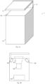
- a device for capturing an image of an imprint of a body part comprises a frame comprising a console 10 surmounted by a screen 12 which extends parallel to a transparent upper face 101 of the desk 10.
- the upper face 101 and the screen 12 are separated by a distance of a few centimeters (for example five centimeters for the acquisition of fingerprints) to define between them a free space zone 14 open, here frontally and laterally on both sides, to form a passage for a finger of the user.
- the console 10 contains an image acquisition module such as a color camera 102 which is mounted in the console 10 to have an optical field covering an acquisition zone 103 which is entirely contained in the free space zone. 14.
- the screen 12 comprises an antireflection treatment on the lower face.
- the acquisition zone 103 is here more precisely at the center of the free space zone 14 and has a plane parallel to the upper face 101.
- the optical field of the camera 102 has a width sufficient for the acquisition zone 103 covers the finger the user (for example an index, a middle, a ring finger, a little finger, or a thumb).
- the camera 102 comprises a sensor, such as a CCD sensor ("Charge Couple Device” in English terminology) or CMOS sensor ("Complementary Metal Oxide Semiconductor” in English terminology) having a sufficiently high acquisition speed to take a sharp image of a moving finger in the acquisition zone 103 with a predetermined maximum speed of movement.
- the sensor used is for example a “1.3” million pixel sensor with a speed of between “60” to “100” images per second.
- the camera 102 is connected to a processing module 104 to which it transmits color images.
- the processing module 104 is described below in relation to the Fig. 7 .
- the frame also comprises a projection module for a light pattern 105 and a light source 106.
- the projection module for a pattern 105 and the light source 106 are fixed to the frame below the passage path of the finger and are directed to acquisition area 103.
- the light source 106 acts as a flash and comprises for example at least one LED (Light-Emitting Diode: "light-emitting diode " in English terminology).
- the light source 106 produces spatially uniform lighting of high intensity in a range of wavelengths corresponding, for example, to green light. In another embodiment, light source 106 emits white light.
- the pattern projection module 105 projects a pattern onto the finger placed in the free space zone 14 perpendicular to the direction of movement of the finger.
- the target comprises a repeating light pattern in the same wavelength range as the light source 106.
- the repeating light pattern comprises light bars of lower light intensity than the light intensity generated by the light source 106 and regularly spaced .
- the light bars are defined here to have an average period on the finger of “70” to “80” pixels at “740” dpi (dots per inch: “dots per inch” in English terminology).
- the light source 106 and the pattern projection module 105 use different wavelength ranges.
- FIG. 2A schematically represents an image acquired by the camera 102 of a projection of the pattern on a sheet of opaque paper placed in the free space zone 14 parallel to the upper face 101.
- the light source 106 is off.
- the target then appears as an alternation of rectangular luminous zones and dark zones.
- Fig. 2B represents a curve of a luminous intensity as a function of a pixel number representative of the luminous intensity of the pixels of a horizontal line of pixels of the image of the projection of the target on a sheet of paper represented in Fig. 2A .
- This curve comprises a succession of regularly spaced rectangular slots. Each rectangular slot can be approximated by a gate function. The transition between dark and light areas (and vice versa) is abrupt here.
- FIG. 3A schematically represents an image acquired by the camera 102 of a projection of the pattern on a finger placed in the free space zone 14 parallel to the upper face 101.
- the light source 106 is off. Since a finger is not a flat surface, but rather a roughly tubular shape, when projecting the staff onto the finger, the bars appear curved as they conform to the shape of the finger.
- Fig. 3B represents a curve of a luminous intensity as a function of a pixel number representative of the luminous intensity of the pixels of a horizontal line of pixels of the image of the projection of the crosshair on a finger represented in Fig. 3A .
- the slots represented in the Fig. 3B appear blunt in the upper part and flared outwards from the crenel in the lower part. Contrary to the sheet of paper which is practically not a diffusing medium, the finger is a diffusing medium. The scattering of light in the finger attenuates the transition between a part illuminated by the target and a part not illuminated by the target. Transitions between lit and unlit parts in the Fig. 3B are softer than in the Fig. 2B .
- Fig. 4 represents an authentication or identification method implemented by the biometric device according to the invention.
- the user wishing to be identified (or authenticated) enters his finger into the free space zone 14 by one side of the latter and moves his finger towards the other side.
- a sensor of the biometric device 1 here an infrared barrier not shown, detects the entry of the finger into the acquisition zone 103.
- the sensor controls a simultaneous activation of the projection module of a target 105, of the light source 106 and an acquisition of an image, called acquired image, by the camera 102.
- the acquired image represents a finger on which a distorted pattern appears.
- the acquired image shows variations in light intensity.
- First variations in light intensity are due to the bars of the pattern and have an average frequency of variation.
- Second light variations are due to optical defects or to defects in the light source 106 which does not illuminate the finger in a perfectly uniform manner. These second light intensity variations have a low variation frequency compared to the variation frequency due to the bars of the test chart.
- Third luminous variations are due to the ridges and valleys of the fingerprint of the finger.
- the processing module 104 eliminates during step 42 the second light variations so that they do not disturb the following steps of the method. To do this, the processing module 104 balances the pixel values of the acquired image. For example, the processing module 104 applies a transformation in the frequency domain to the acquired image in order to convert this image from the spatial domain to the frequency domain. In the frequency domain, the processing module 104 eliminates the low spatial frequencies of the transformed acquired image then applies an inverse transformation to the transformed acquired image thus modified.
- the sensor of the biometric device 1 could have been replaced by a button on which the user presses to simultaneously activate the projection module of a pattern 105, the light source 106 and the camera 102 when the finger is in the acquisition zone.
- the processing module 104 models the light intensity variations of the projection of the test pattern on the finger using a predetermined parametric mathematical model.
- the predetermined mathematical model is based on a logistic function.
- the logistic function is particularly suitable for modeling abrupt (quasi-rectangular) variations of a one-dimensional signal such as that encountered in a rising variation or a falling variation of a slot of the Fig. 3B .
- the parameter K sets a maximum amplitude of the variation
- the parameter r fixes a slope of the variation
- the parameter a fixes a shape of the variation.
- the modeling implemented during step 43 then consists in determining the parameters of the predetermined parametric mathematical model (i.e. for example the parameters a, K, r, b and s of the function g(x) or of the function h(x)) making it possible to better model the variations in light intensity due to the pattern in the acquired image.
- the parameters of the predetermined parametric mathematical model i.e. for example the parameters a, K, r, b and s of the function g(x) or of the function h(x)
- Step 43 is detailed below in relation to the Fig. 5 .
- the processing module 104 generates an image of the projection of the target on the finger, called a synthetic image, according to a method described in relation to the Fig. 6 from the predetermined parametric mathematical model using the parameters determined during step 43 and subtracts the synthetic image from the acquired image in order to obtain an image of the finger without a target. It would have been possible to search for the test pattern in the acquired image, for example by using an image segmentation method. However, the image of the pattern obtained would have been noisy and the subtraction of this noisy image from the acquired image would have amplified a noise already present in the acquired image. Generate a synthetic image from the parametric mathematical model predetermined makes it possible to obtain an image with no (or little) noise. Thus, by subtracting the synthetic image from the acquired image, the noise already present in the acquired image is not amplified. This increases the performance of the biometric system 1 for authentication and identification.
- the processing module 104 obtains three-dimensional (3D) information on the body part from information on the position of the target in the acquired image.
- the 3D information is used to generate a final fingerprint image from the targetless finger image in which the fingerprint is flattened and scaled back to a predetermined scale corresponding to a scale of at least one image d reference fingerprint with which the final fingerprint image should be compared.
- the processing module 104 uses known flattening and scaling methods for this, such as the method described in the article " 3D Touchless fingerprints compatibility with legacy rolled images”, Y. Chen et al., In Biometry Consortium Conference, Aug. 21 2006 Page(s): 1 - 6 .
- the final fingerprint image is compared with a reference fingerprint image for authentication or with a plurality of reference fingerprint images for identification.
- Fig. 5 represents an example of a method for modeling the light intensity variations of the projection of the test pattern on a finger using a predetermined parametric mathematical model.
- step 43 The process described in Fig. 5 details step 43.
- the processing module 104 scans the acquired image line by line and from top to bottom.
- the finger is assumed to appear horizontal in the acquired image as represented schematically in the Fig. 3A .
- the distance between the first (respectively the second) pixel and the preceding pixel is a predetermined distance (measured in pixels).
- the first and second thresholds and the predetermined distance are determined from a large panel of acquired images obtained using the biometric device 1.
- step 432 slot location information such as the position of the current slot in the line (pixel number of the start of the slot, pixel number of the end of the slot) and the number of the line currently being routes are saved in the memory of the processing module 104.
- the processing module 104 determines parameters of the predetermined parametric mathematical model adapted to the slot detected during step 432.
- the processing module 104 searches for the parameters K, a, r, b and s such that the function g(x) (respectively h(x)) best matches the shape of the slot found during step 432.
- the processing module 104 varies the parameters K, a, r, b and s , until finding a set of parameters minimizing a difference between a slot given by the function g(x) (respectively h(x )) and the slot found during step 432.
- Said parameters can for example be determined by a gradient descent method or by a least squares method.
- the parameter r which is relatively constant from one finger to the other is predetermined using a large panel of acquired images obtained using the biometric device 1.
- the parameter r being strongly influenced by the high spatial frequencies (typically the spatial frequencies due to the peaks and the valleys), it is advantageous to fix this parameter so that the determination of the other parameters of the model is not disturbed by said high spatial frequencies.
- the parameters K, a, r, b and s thus determined are stored in the memory of the processing module 104 with the slot location information.
- the processing module 104 determines during a step 434 whether the entire line has been traversed and if this is not the case, returns to step 432 to search for a new time slot or finish the course of the line.
- the processing module 104 determines during a step 435 whether another line must be examined. If so, the processing module returns to step 432 and begins to search for a slot in a new line.
- the processing module 104 terminates the process of the Fig. 5 during a step 436.
- a list of slots of the acquired image is obtained, each represented by parameters K, a, r, b and s of the predetermined parametric mathematical model and location information.
- FIG. 6 represents an example of a method for generating a synthetic image of the invention.
- the processing module 104 From the list of slots obtained during step 43, the processing module 104 generates a synthetic image representing the projection of the test pattern on the finger.
- a step 442 the processing module determines whether it has gone through the entire list of slots. If the entire list of slots has been scanned, the process ends. The synthetic image was then generated.
- processing module 104 obtains the position of a current slot in the acquired image and generates light intensities from the parametric mathematical model at said position. Following step 443, processing module 104 returns to step 442, and if the list of slots has not been completely scanned, returns to step 443 for a new slot.
- the synthetic image when the acquired image is a multi-component image having several components such as a luminance component and two chrominance components, the synthetic image is also a multi-component image.
- the processes of Figs. 5 And 6 are applied to each component one by one.
- the subtraction of the synthetic image from the acquired image is done in each component taken one by one.
- FIG. 7 schematically illustrates an example of hardware architecture of the processing module 11.
- the processing module 104 then comprises, connected by a communication bus 1040: a processor or CPU (Central Processing Unit) 1041; a living memory RAM (Random Access Memory) 1042; a read-only memory ROM 1043; a storage unit such as a hard disk or a storage medium reader, such as an SD (Secure Digital) card reader 1044; at least one communication interface 1045 allowing for example the processing module 104 to communicate with the camera 102, the light source 106 and the pattern projection module 105.
- a communication bus 1040 a processor or CPU (Central Processing Unit) 1041; a living memory RAM (Random Access Memory) 1042; a read-only memory ROM 1043; a storage unit such as a hard disk or a storage medium reader, such as an SD (Secure Digital) card reader 1044; at least one communication interface 1045 allowing for example the processing module 104 to communicate with the camera 102, the light source 106 and the pattern projection module 105.
- a communication bus 1040 a processor
- Processor 1041 is capable of executing instructions loaded into RAM 1042 from ROM 1043, external memory (not shown), storage media (such as an SD card), or a communications network. When processing module 104 is powered up, processor 1041 is able to read instructions from RAM 1042 and execute them. These instructions form a computer program causing the implementation, by the processor 1041, of the method described in relation to the Fig. 4 .
- the process described in relation to the Fig. 4 can be implemented in software form by executing a set of instructions by a programmable machine, for example a DSP ("Digital Signal Processor” in English), a microcontroller or a GPU (graphics processor, "Graphics Processing Unit” in terminology Anglo-Saxon), or be implemented in hardware form by a dedicated machine or component, for example an FPGA (Field-Programmable Gate Array) or an ASIC (Application-Specific Integrated Circuit).
- a programmable machine for example a DSP ("Digital Signal Processor” in English
- a microcontroller or a GPU graphics processor, "Graphics Processing Unit” in terminology Anglo-Saxon
- FPGA Field-Programmable Gate Array
- ASIC Application-Specific Integrated Circuit
Landscapes
- Engineering & Computer Science (AREA)
- Physics & Mathematics (AREA)
- Theoretical Computer Science (AREA)
- General Physics & Mathematics (AREA)
- Multimedia (AREA)
- Software Systems (AREA)
- General Engineering & Computer Science (AREA)
- Data Mining & Analysis (AREA)
- Computer Security & Cryptography (AREA)
- Mathematical Physics (AREA)
- Mathematical Optimization (AREA)
- Computational Mathematics (AREA)
- Pure & Applied Mathematics (AREA)
- Mathematical Analysis (AREA)
- Artificial Intelligence (AREA)
- Computer Vision & Pattern Recognition (AREA)
- Human Computer Interaction (AREA)
- Algebra (AREA)
- Computer Hardware Design (AREA)
- Bioinformatics & Computational Biology (AREA)
- Operations Research (AREA)
- Probability & Statistics with Applications (AREA)
- Evolutionary Biology (AREA)
- Bioinformatics & Cheminformatics (AREA)
- Life Sciences & Earth Sciences (AREA)
- Databases & Information Systems (AREA)
- Evolutionary Computation (AREA)
- Computing Systems (AREA)
- Collating Specific Patterns (AREA)
- Image Input (AREA)
Claims (11)
- Vorrichtung zum Erfassen eines Bildes von einem Abdruck eines Körperteils, die ein Bilderfassungsmodul (102) mit einem Sichtfeld, das einen Erfassungsbereich (103) abdeckt, in dem sich der Körperteil hin und her bewegen kann, eine Lichtquelle (106), die eine räumlich gleichmäßige Beleuchtung des Körperteils erzeugt, und ein Musterprojektionsmodul (105) umfasst, das ein Lichtmuster auf den Körperteil senkrecht zu einer Bewegungsrichtung des Fingers projiziert, dadurch gekennzeichnet, dass:das Lichtmuster ein sich wiederholendes Motiv mit geringerer Lichtintensität als die gleichmäßige Beleuchtung ist, wobei das sich wiederholende Motiv im selben Wellenlängenbereich wie die Lichtquelle liegt;wobei die Vorrichtung geeignet ist zum:gleichzeitigen Aktivieren (42) der Lichtquelle, des Musterprojektionsmoduls und des Bilderfassungsmoduls, um eine Erfassung eines Bildes des Abdrucks, erfasstes Bild genannt, zu ermöglichen;Modellieren (43) von Variationen der Lichtintensität der Musterprojektion auf den Körperteil durch Bestimmen von Parametern eines vorgegebenen parametrischen mathematischen 1D-Modells, wobei das vorgegebene parametrische Modell ein 1D-Modell ist, das durch Pixelzeilen und die Funktion einer Pixelnummer in der Zeile definiert ist;Erzeugen (44) eines Bildes der Musterprojektion auf den Körperteil, synthetisches Bild genannt, auf Grundlage des Modells unter Verwendung der zuvor bestimmten Parameter und Subtrahieren des synthetischen Bildes vom erfassten Bild, um ein Bild des Körperteils ohne Muster zu erhalten, wobei das Bild des Körperteils ohne Muster zur Identifizierung oder Authentifizierung verwendet werden kann (45, 46).
- Vorrichtung nach Anspruch 1, dadurch gekennzeichnet, dass die Vorrichtung bei der Modellierung dazu eingerichtet ist, das erfasste Bild zeilenweise zu durchlaufen und eine Kurve der Lichtintensität in Abhängigkeit von einer Pixelnummer für jede Zeile zu erhalten, wobei jede Kurve eine Vielzahl von Lücken umfasst, wobei jede Lücke durch eine Funktion modelliert wird, die von einer logistischen Funktion abgeleitet ist.
- Vorrichtung nach Anspruch 2, dadurch gekennzeichnet, dass die Vorrichtung dazu eingerichtet ist, jede Lücke jeder Linie zu erkennen, wobei eine Lücke in einer Lichtintensitätskurve erkannt wird, wenn eine erste Änderung der Lichtintensität zwischen einem ersten Pixel und einem Pixel, das diesem ersten Pixel in einer Laufrichtung der vorbestimmten Linie vorausgeht, positiv ist und im absoluten Wert größer als ein erster vorbestimmter Schwellenwert ist; wenn auf die erste Änderung der Lichtintensität eine zweite Änderung der Lichtintensität zwischen einem zweiten Pixel und einem Pixel folgt, das diesem zweiten Pixel in der Laufrichtung der vorbestimmten Linie vorausgeht, wobei diese zweite Änderung negativ ist und im absoluten Wert größer als der erste vorbestimmte Schwellenwert ist, und wenn der Abstand in der Anzahl der Pixel zwischen der ersten Änderung und der zweiten Änderung größer als ein zweiter vorbestimmter Schwellenwert ist.
- Vorrichtung nach Anspruch 2 oder 3 dadurch gekennzeichnet, dass die von einer logistischen Funktion abgeleitete Funktion gegeben ist durch:


- Vorrichtung nach Anspruch 4, dadurch gekennzeichnet, dass der Parameter a und/oder der Parameter r vorbestimmt sind.
- Vorrichtung nach einem der Ansprüche 2 bis 5, dadurch gekennzeichnet, dass die Vorrichtung infolge der Modellierung dazu geeignet ist, eine Liste von Lücken zu erhalten, wobei jede Lücke der Liste durch die bestimmten Parameter des Modells und durch eine Position der Lücke im erfassten Bild dargestellt ist, und das synthetische Bild auf Grundlage jeder Lücke der Liste zu erzeugen.
- Verfahren zur Authentifizierung oder Identifizierung, dadurch gekennzeichnet, dass es umfasst:Erhalten eines Bildes, erfasstes Bild genannt, als Ergebnis einer gleichzeitigen Aktivierung (42) einer Lichtquelle, eines Musterprojektionsmoduls und eines Bilderfassungsmoduls in einer Vorrichtung zur Erfassung eines Bildes von einem Abdruck eines Körperteils, wobei das Bilderfassungsmodul (102) ein Sichtfeld hat, das einen Erfassungsbereich (103) abdeckt, in dem sich der Körperteil hin und her bewegen kann, wobei die Lichtquelle (106) eine räumlich gleichmäßige Beleuchtung über dem Körperteil erzeugt und das Musterprojektionsmodul (105) ein Lichtmuster auf den Körperteil senkrecht zu einer Bewegungsrichtung des Fingers projiziert, das Lichtmuster ein sich wiederholendes Muster mit geringerer Lichtintensität als die gleichmäßige Beleuchtung ist, wobei das sich wiederholende Muster im selben Wellenlängenbereich wie die Lichtquelle liegt;Modellieren (43) der Lichtintensitätsänderungen der Musterprojektion auf den Körperteil durch Bestimmen der Parameter eines vorbestimmten parametrischen mathematischen 1D-Modells, wobei das vorbestimmte parametrische Modell ein 1D-Modell ist, das durch Pixelzeilen und die Funktion einer Pixelnummer in der Zeile definiert ist;Erzeugen (44) eines Bildes der Musterprojektion auf den Körperteil, synthetisches Bild genannt, auf Grundlage des Modells unter Verwendung der zuvor bestimmten Parameter und Subtrahieren des synthetischen Bildes vom erfassten Bild, um ein Bild des Körperteils ohne Muster zu erhalten, wobei das Bild des Körperteils ohne Muster bei einer Identifizierung oder Authentifizierung verwendet werden kann.
- Verfahren nach Anspruch 7, dadurch gekennzeichnet, dass Modellieren ein zeilenweises Durchlaufen des erfassten Bildes und Erhalten einer Lichtintensitätskurve in Abhängigkeit von der Pixelnummer für jede Zeile umfasst, wobei jede Kurve eine Vielzahl von Lücken umfasst, wobei jede Lücke durch eine Funktion modelliert wird, die von einer logistischen Funktion abgeleitet ist.
- Verfahren nach Anspruch 7 oder 8, dadurch gekennzeichnet, dass es umfasst:Erhalten (45) der dreidimensionalen Informationen über den Körperteil auf Grundlage von Informationen über die Position des Musters im erfassten Bild und Verwenden der Informationen, um ein endgültiges Abdruckbild auf Grundlage des Bildes des Körperteils ohne Muster zu erzeugen, in dem der Abdruck flach angeordnet und auf einen Maßstab gebracht wird, der einem vorbestimmten Maßstab entspricht; undVergleichen (46) des endgültigen Abdruckbildes mit mindestens einem Referenzabdruckbild, um die Authentifizierung oder Identifizierung durchzuführen.
- Computerprogramm, dadurch gekennzeichnet, dass es Anweisungen zum Ausführen des Verfahrens nach den Ansprüchen 7 bis 9 durch eine Vorrichtung nach Anspruch 1 umfasst, wenn das Programm von einer Recheneinheit der Vorrichtung ausgeführt wird.
- Speichermedien, dadurch gekennzeichnet, dass sie ein Computerprogramm speichern, das Anweisungen zum Ausführen des Verfahrens nach Anspruch 7 bis 9 durch eine Vorrichtung nach Anspruch 1 umfasst, wenn das Programm von einer Recheneinheit der Vorrichtung ausgeführt wird.
Applications Claiming Priority (1)
| Application Number | Priority Date | Filing Date | Title |
|---|---|---|---|
| FR1754070A FR3066294B1 (fr) | 2017-05-10 | 2017-05-10 | Dispositif de capture d'empreintes |
Publications (3)
| Publication Number | Publication Date |
|---|---|
| EP3401837A1 EP3401837A1 (de) | 2018-11-14 |
| EP3401837B1 true EP3401837B1 (de) | 2023-07-12 |
| EP3401837C0 EP3401837C0 (de) | 2023-07-12 |
Family
ID=59811427
Family Applications (1)
| Application Number | Title | Priority Date | Filing Date |
|---|---|---|---|
| EP18170809.0A Active EP3401837B1 (de) | 2017-05-10 | 2018-05-04 | Vorrichtung zum abnehmen von fingerabdrücken |
Country Status (4)
| Country | Link |
|---|---|
| US (1) | US10460145B2 (de) |
| EP (1) | EP3401837B1 (de) |
| KR (1) | KR102609505B1 (de) |
| FR (1) | FR3066294B1 (de) |
Families Citing this family (4)
| Publication number | Priority date | Publication date | Assignee | Title |
|---|---|---|---|---|
| DE202020005521U1 (de) | 2020-11-27 | 2021-07-01 | JENETRIC GmbH | Vorrichtung zur berührungslosen optischen Abbildung eines ausgewählten Oberflächenbereiches einer Hand |
| DE102020131513B3 (de) | 2020-11-27 | 2022-01-27 | JENETRIC GmbH | Vorrichtung und Verfahren zur berührungslosen optischen Abbildung eines ausgewählten Oberflächenbereiches einer Hand |
| DE102021111422A1 (de) | 2021-05-04 | 2022-11-10 | IDloop GmbH | Vorrichtung und Verfahren zur kontaktlosen Aufnahme von Finger- und Handabdrücken |
| FR3123747A1 (fr) * | 2021-06-02 | 2022-12-09 | Idemia Identity & Security France | Capteur et procédé d’acquisition biométrique sans contact |
Family Cites Families (14)
| Publication number | Priority date | Publication date | Assignee | Title |
|---|---|---|---|---|
| US6433818B1 (en) * | 1998-11-06 | 2002-08-13 | Fotonation, Inc. | Digital camera with biometric security |
| US5801681A (en) * | 1996-06-24 | 1998-09-01 | Sayag; Michel | Method and apparatus for generating a control signal |
| US6919959B2 (en) * | 1999-06-30 | 2005-07-19 | Masten Opto-Diagnostics Co. | Digital spectral identifier-controller and related methods |
| GB0031016D0 (en) * | 2000-12-20 | 2001-01-31 | Alphafox Systems Ltd | Security systems |
| JP2002259954A (ja) * | 2001-02-28 | 2002-09-13 | Nec Corp | 指紋認証の結果表示装置、及び、その結果表示方法 |
| JP2003006627A (ja) * | 2001-06-18 | 2003-01-10 | Nec Corp | 指紋入力装置 |
| JP2003032455A (ja) * | 2001-07-16 | 2003-01-31 | Canon Inc | 画像処理装置及びシステム |
| JP3858263B2 (ja) * | 2001-11-09 | 2006-12-13 | 日本電気株式会社 | 指紋画像入力装置及びそれを用いた電子機器 |
| US8224064B1 (en) * | 2003-05-21 | 2012-07-17 | University Of Kentucky Research Foundation, Inc. | System and method for 3D imaging using structured light illumination |
| WO2005072240A2 (en) * | 2004-01-23 | 2005-08-11 | Ultra-Scan Corporation | Fingerprint scanner and method having an acoustic detector |
| FR2927713B1 (fr) * | 2008-02-14 | 2011-08-26 | Sagem Securite | Dispositif d'acquisition d'empreintes digitales a la volee. |
| DE102010016109A1 (de) * | 2010-03-24 | 2011-09-29 | Tst Biometrics Holding Ag | Verfahren zum Erfassen biometrischer Merkmale |
| CA2851225A1 (en) * | 2010-10-08 | 2012-04-12 | Advanced Optical Systems, Inc. | Contactless fingerprint acquisition and processing |
| US10417472B2 (en) * | 2014-01-10 | 2019-09-17 | Koh Young Technology Inc. | Device and method for measuring three-dimensional shape |
-
2017
- 2017-05-10 FR FR1754070A patent/FR3066294B1/fr active Active
-
2018
- 2018-05-04 EP EP18170809.0A patent/EP3401837B1/de active Active
- 2018-05-07 US US15/972,732 patent/US10460145B2/en active Active
- 2018-05-10 KR KR1020180053765A patent/KR102609505B1/ko active IP Right Grant
Also Published As
| Publication number | Publication date |
|---|---|
| KR20180123990A (ko) | 2018-11-20 |
| EP3401837A1 (de) | 2018-11-14 |
| FR3066294B1 (fr) | 2019-06-28 |
| US20180330142A1 (en) | 2018-11-15 |
| KR102609505B1 (ko) | 2023-12-01 |
| EP3401837C0 (de) | 2023-07-12 |
| US10460145B2 (en) | 2019-10-29 |
| FR3066294A1 (fr) | 2018-11-16 |
Similar Documents
| Publication | Publication Date | Title |
|---|---|---|
| EP3401837B1 (de) | Vorrichtung zum abnehmen von fingerabdrücken | |
| US10339362B2 (en) | Systems and methods for performing fingerprint based user authentication using imagery captured using mobile devices | |
| US11263432B2 (en) | Systems and methods for performing fingerprint based user authentication using imagery captured using mobile devices | |
| KR102561723B1 (ko) | 모바일 디바이스를 사용하여 캡처된 화상을 사용하여 지문 기반 사용자 인증을 수행하기 위한 시스템 및 방법 | |
| Kose et al. | Reflectance analysis based countermeasure technique to detect face mask attacks | |
| EP2901370B1 (de) | Verfahren zur erkennung eines realen gesichts | |
| US9076048B2 (en) | Biometric identification, authentication and verification using near-infrared structured illumination combined with 3D imaging of the human ear | |
| EP2751739B1 (de) | Betrugserkennung in einem biometrischen zugangskontrollsystem | |
| EP3382605A1 (de) | Analyseverfahren eines strukturierten dokuments, das verformbar ist | |
| EP3044729B1 (de) | Validierungsverfahren zur validierung der abdeckung eines elements durch echte haut | |
| FR2915301A1 (fr) | Procede de comparaison d'images d'une biometrie entre au moi ns une image de reference et au moins une image de test dont on cherche a evaluer un degre de correlation avec l'image d e reference | |
| FR3053500B1 (fr) | Procede de detection de fraude d'un systeme de reconnaissance d'iris | |
| EP3388976B1 (de) | Betrugserkennungsverfahren | |
| WO2020109122A1 (fr) | Dispositif et procede d'authentification d'un individu | |
| FR3011960A1 (fr) | Procede d'identification a partir d'un modele spatial et spectral d'objet | |
| EP3073441B1 (de) | Verfahren zur korrektur eines bildes mindestens eines objekts, das vor einem bildanzeigegerät in der ferne dargestellt und von einem beleuchtungssystem beleuchtet wird, und bildaufnahmesystem für die umsetzung dieses verfahrens | |
| EP3471016A1 (de) | Präsenzerkennungsverfahren eines körperteils, der einen fingerabdruck auf einem fingerabdrucksensor erzeugen kann | |
| CN112906613A (zh) | 一种身份信息采集方法及装置 | |
| FR3126529A1 (fr) | Procédé de mise en relation d’une image candidate avec une image de référence. | |
| FR3032539A1 (fr) | Procede d'acquisition de donnees biometriques selon une sequence verifiee | |
| FR3059449A1 (fr) | Procede de detection de fraude d'un systeme de reconnaissance d'iris | |
| Al-Badarneh | Oil Paintings Authentication Using Digital Image Processing |
Legal Events
| Date | Code | Title | Description |
|---|---|---|---|
| PUAI | Public reference made under article 153(3) epc to a published international application that has entered the european phase |
Free format text: ORIGINAL CODE: 0009012 |
|
| STAA | Information on the status of an ep patent application or granted ep patent |
Free format text: STATUS: REQUEST FOR EXAMINATION WAS MADE |
|
| 17P | Request for examination filed |
Effective date: 20180518 |
|
| AK | Designated contracting states |
Kind code of ref document: A1 Designated state(s): AL AT BE BG CH CY CZ DE DK EE ES FI FR GB GR HR HU IE IS IT LI LT LU LV MC MK MT NL NO PL PT RO RS SE SI SK SM TR |
|
| AX | Request for extension of the european patent |
Extension state: BA ME |
|
| RAP1 | Party data changed (applicant data changed or rights of an application transferred) |
Owner name: IDEMIA IDENTITY & SECURITY FRANCE |
|
| STAA | Information on the status of an ep patent application or granted ep patent |
Free format text: STATUS: EXAMINATION IS IN PROGRESS |
|
| 17Q | First examination report despatched |
Effective date: 20200504 |
|
| STAA | Information on the status of an ep patent application or granted ep patent |
Free format text: STATUS: EXAMINATION IS IN PROGRESS |
|
| STAA | Information on the status of an ep patent application or granted ep patent |
Free format text: STATUS: EXAMINATION IS IN PROGRESS |
|
| REG | Reference to a national code |
Ref country code: DE Ref legal event code: R079 Ref document number: 602018053095 Country of ref document: DE Free format text: PREVIOUS MAIN CLASS: G06K0009000000 Ipc: G06V0040130000 Ref country code: DE Ref legal event code: R079 Free format text: PREVIOUS MAIN CLASS: G06K0009000000 Ipc: G06V0040130000 |
|
| GRAP | Despatch of communication of intention to grant a patent |
Free format text: ORIGINAL CODE: EPIDOSNIGR1 |
|
| STAA | Information on the status of an ep patent application or granted ep patent |
Free format text: STATUS: GRANT OF PATENT IS INTENDED |
|
| RIC1 | Information provided on ipc code assigned before grant |
Ipc: G06V 40/13 20220101AFI20230302BHEP |
|
| INTG | Intention to grant announced |
Effective date: 20230331 |
|
| GRAS | Grant fee paid |
Free format text: ORIGINAL CODE: EPIDOSNIGR3 |
|
| GRAA | (expected) grant |
Free format text: ORIGINAL CODE: 0009210 |
|
| STAA | Information on the status of an ep patent application or granted ep patent |
Free format text: STATUS: THE PATENT HAS BEEN GRANTED |
|
| AK | Designated contracting states |
Kind code of ref document: B1 Designated state(s): AL AT BE BG CH CY CZ DE DK EE ES FI FR GB GR HR HU IE IS IT LI LT LU LV MC MK MT NL NO PL PT RO RS SE SI SK SM TR |
|
| REG | Reference to a national code |
Ref country code: CH Ref legal event code: EP |
|
| REG | Reference to a national code |
Ref country code: DE Ref legal event code: R096 Ref document number: 602018053095 Country of ref document: DE |
|
| REG | Reference to a national code |
Ref country code: IE Ref legal event code: FG4D Free format text: LANGUAGE OF EP DOCUMENT: FRENCH |
|
| U01 | Request for unitary effect filed |
Effective date: 20230712 |
|
| U07 | Unitary effect registered |
Designated state(s): AT BE BG DE DK EE FI FR IT LT LU LV MT NL PT SE SI Effective date: 20230720 |
|
| REG | Reference to a national code |
Ref country code: LT Ref legal event code: MG9D |
|
| PG25 | Lapsed in a contracting state [announced via postgrant information from national office to epo] |
Ref country code: GR Free format text: LAPSE BECAUSE OF FAILURE TO SUBMIT A TRANSLATION OF THE DESCRIPTION OR TO PAY THE FEE WITHIN THE PRESCRIBED TIME-LIMIT Effective date: 20231013 |
|
| PG25 | Lapsed in a contracting state [announced via postgrant information from national office to epo] |
Ref country code: ES Free format text: LAPSE BECAUSE OF FAILURE TO SUBMIT A TRANSLATION OF THE DESCRIPTION OR TO PAY THE FEE WITHIN THE PRESCRIBED TIME-LIMIT Effective date: 20230712 |
|
| PG25 | Lapsed in a contracting state [announced via postgrant information from national office to epo] |
Ref country code: IS Free format text: LAPSE BECAUSE OF FAILURE TO SUBMIT A TRANSLATION OF THE DESCRIPTION OR TO PAY THE FEE WITHIN THE PRESCRIBED TIME-LIMIT Effective date: 20231112 |
|
| PG25 | Lapsed in a contracting state [announced via postgrant information from national office to epo] |
Ref country code: RS Free format text: LAPSE BECAUSE OF FAILURE TO SUBMIT A TRANSLATION OF THE DESCRIPTION OR TO PAY THE FEE WITHIN THE PRESCRIBED TIME-LIMIT Effective date: 20230712 Ref country code: NO Free format text: LAPSE BECAUSE OF FAILURE TO SUBMIT A TRANSLATION OF THE DESCRIPTION OR TO PAY THE FEE WITHIN THE PRESCRIBED TIME-LIMIT Effective date: 20231012 Ref country code: IS Free format text: LAPSE BECAUSE OF FAILURE TO SUBMIT A TRANSLATION OF THE DESCRIPTION OR TO PAY THE FEE WITHIN THE PRESCRIBED TIME-LIMIT Effective date: 20231112 Ref country code: HR Free format text: LAPSE BECAUSE OF FAILURE TO SUBMIT A TRANSLATION OF THE DESCRIPTION OR TO PAY THE FEE WITHIN THE PRESCRIBED TIME-LIMIT Effective date: 20230712 Ref country code: GR Free format text: LAPSE BECAUSE OF FAILURE TO SUBMIT A TRANSLATION OF THE DESCRIPTION OR TO PAY THE FEE WITHIN THE PRESCRIBED TIME-LIMIT Effective date: 20231013 Ref country code: ES Free format text: LAPSE BECAUSE OF FAILURE TO SUBMIT A TRANSLATION OF THE DESCRIPTION OR TO PAY THE FEE WITHIN THE PRESCRIBED TIME-LIMIT Effective date: 20230712 |
|
| PG25 | Lapsed in a contracting state [announced via postgrant information from national office to epo] |
Ref country code: PL Free format text: LAPSE BECAUSE OF FAILURE TO SUBMIT A TRANSLATION OF THE DESCRIPTION OR TO PAY THE FEE WITHIN THE PRESCRIBED TIME-LIMIT Effective date: 20230712 |
|
| REG | Reference to a national code |
Ref country code: DE Ref legal event code: R097 Ref document number: 602018053095 Country of ref document: DE |
|
| PG25 | Lapsed in a contracting state [announced via postgrant information from national office to epo] |
Ref country code: SM Free format text: LAPSE BECAUSE OF FAILURE TO SUBMIT A TRANSLATION OF THE DESCRIPTION OR TO PAY THE FEE WITHIN THE PRESCRIBED TIME-LIMIT Effective date: 20230712 Ref country code: RO Free format text: LAPSE BECAUSE OF FAILURE TO SUBMIT A TRANSLATION OF THE DESCRIPTION OR TO PAY THE FEE WITHIN THE PRESCRIBED TIME-LIMIT Effective date: 20230712 Ref country code: CZ Free format text: LAPSE BECAUSE OF FAILURE TO SUBMIT A TRANSLATION OF THE DESCRIPTION OR TO PAY THE FEE WITHIN THE PRESCRIBED TIME-LIMIT Effective date: 20230712 Ref country code: SK Free format text: LAPSE BECAUSE OF FAILURE TO SUBMIT A TRANSLATION OF THE DESCRIPTION OR TO PAY THE FEE WITHIN THE PRESCRIBED TIME-LIMIT Effective date: 20230712 |
|
| PLBE | No opposition filed within time limit |
Free format text: ORIGINAL CODE: 0009261 |
|
| STAA | Information on the status of an ep patent application or granted ep patent |
Free format text: STATUS: NO OPPOSITION FILED WITHIN TIME LIMIT |
|
| U20 | Renewal fee paid [unitary effect] |
Year of fee payment: 7 Effective date: 20240418 |
|
| 26N | No opposition filed |
Effective date: 20240415 |