EP2423616A2 - Heizblock und Dichtungselement für einen Heizblock - Google Patents
Heizblock und Dichtungselement für einen Heizblock Download PDFInfo
- Publication number
- EP2423616A2 EP2423616A2 EP11177619A EP11177619A EP2423616A2 EP 2423616 A2 EP2423616 A2 EP 2423616A2 EP 11177619 A EP11177619 A EP 11177619A EP 11177619 A EP11177619 A EP 11177619A EP 2423616 A2 EP2423616 A2 EP 2423616A2
- Authority
- EP
- European Patent Office
- Prior art keywords
- channels
- heating
- heating block
- cover
- base body
- Prior art date
- Legal status (The legal status is an assumption and is not a legal conclusion. Google has not performed a legal analysis and makes no representation as to the accuracy of the status listed.)
- Granted
Links
- 238000010438 heat treatment Methods 0.000 claims abstract description 86
- 238000007789 sealing Methods 0.000 claims abstract description 75
- XLYOFNOQVPJJNP-UHFFFAOYSA-N water Substances O XLYOFNOQVPJJNP-UHFFFAOYSA-N 0.000 claims description 28
- 239000008236 heating water Substances 0.000 claims description 8
- 230000015572 biosynthetic process Effects 0.000 claims description 2
- 238000000926 separation method Methods 0.000 abstract 1
- 238000004519 manufacturing process Methods 0.000 description 8
- 238000005192 partition Methods 0.000 description 6
- 230000004323 axial length Effects 0.000 description 4
- 238000005516 engineering process Methods 0.000 description 3
- 239000012530 fluid Substances 0.000 description 3
- 238000002347 injection Methods 0.000 description 3
- 239000007924 injection Substances 0.000 description 3
- 238000001746 injection moulding Methods 0.000 description 3
- 238000009434 installation Methods 0.000 description 2
- 238000011144 upstream manufacturing Methods 0.000 description 2
- 238000010411 cooking Methods 0.000 description 1
- 230000002950 deficient Effects 0.000 description 1
- 230000001419 dependent effect Effects 0.000 description 1
- 238000013461 design Methods 0.000 description 1
- 238000011161 development Methods 0.000 description 1
- 230000018109 developmental process Effects 0.000 description 1
- 238000007599 discharging Methods 0.000 description 1
- 238000007654 immersion Methods 0.000 description 1
- 238000003780 insertion Methods 0.000 description 1
- 230000037431 insertion Effects 0.000 description 1
- 238000012423 maintenance Methods 0.000 description 1
- 238000002360 preparation method Methods 0.000 description 1
- 238000004904 shortening Methods 0.000 description 1
- 239000000243 solution Substances 0.000 description 1
Images




Classifications
-
- F—MECHANICAL ENGINEERING; LIGHTING; HEATING; WEAPONS; BLASTING
- F24—HEATING; RANGES; VENTILATING
- F24H—FLUID HEATERS, e.g. WATER OR AIR HEATERS, HAVING HEAT-GENERATING MEANS, e.g. HEAT PUMPS, IN GENERAL
- F24H1/00—Water heaters, e.g. boilers, continuous-flow heaters or water-storage heaters
- F24H1/10—Continuous-flow heaters, i.e. heaters in which heat is generated only while the water is flowing, e.g. with direct contact of the water with the heating medium
- F24H1/101—Continuous-flow heaters, i.e. heaters in which heat is generated only while the water is flowing, e.g. with direct contact of the water with the heating medium using electric energy supply
- F24H1/102—Continuous-flow heaters, i.e. heaters in which heat is generated only while the water is flowing, e.g. with direct contact of the water with the heating medium using electric energy supply with resistance
- F24H1/103—Continuous-flow heaters, i.e. heaters in which heat is generated only while the water is flowing, e.g. with direct contact of the water with the heating medium using electric energy supply with resistance with bare resistances in direct contact with the fluid
-
- F—MECHANICAL ENGINEERING; LIGHTING; HEATING; WEAPONS; BLASTING
- F24—HEATING; RANGES; VENTILATING
- F24H—FLUID HEATERS, e.g. WATER OR AIR HEATERS, HAVING HEAT-GENERATING MEANS, e.g. HEAT PUMPS, IN GENERAL
- F24H9/00—Details
- F24H9/18—Arrangement or mounting of grates or heating means
- F24H9/1809—Arrangement or mounting of grates or heating means for water heaters
- F24H9/1818—Arrangement or mounting of electric heating means
Definitions
- the invention relates to a heating block for an electrically heated water heater in bare wire for heating water according to the preamble of claim 1, comprising a main body in which a plurality of heating channels for defining a heating section, a plurality of flow channels for defining a flow path and a plurality of Trailing channels are designed to define a trailing path, which are open at least on one side, and at least one lid for closing the channels on one side, and a sealing element for such a heating block for arrangement in a parting plane between a water-carrying body and a lid for closing in the body running water-bearing channels.
- Such a heating block is z. B. in the German utility model DE 201 08 117 U 1 shown.
- This is intended for an electric water heater in bare wire technology and has a three-part housing, which is formed by a base body and two lids.
- the channels can be closed at the ends by means of the covers, deflection regions for connecting adjacent channels being formed on the covers in order to reduce an axial length of the heating block, said zones projecting in sections into the channels and thus into the base body.
- a sealing element is provided in a parting plane between the base body and the respective lid.
- a disadvantage of this heating block is the elaborate production of the lid, since in their preparation in addition to structurally necessary stiffening ribs, mounting flanges and drgl. The deflection are to be formed with
- the object of the invention is to provide a heating block for an electric water heater in bare wire technology, which eliminates the aforementioned disadvantages and whose manufacturing and assembly costs is reduced, and to provide a sealing element for such a heating block.
- a heater block according to the invention for an electrically heated water heater for heating water has a base body in which a plurality of heating channels for defining a heating section, a plurality of flow channels for defining a delay line and a plurality of follow-up channels are defined for defining a catenary are open at least on one side, and at least one lid for closing the channels.
- a sealing element is provided for arranging in a parting plane between the housing and the cover, which has deflection regions for the end-side connection of adjacent channels.
- the axial length of the heating block can be reduced if the deflection areas in the mounted state of the heating block dive into both the channels and in chambers of the lid. In one exemplary embodiment, this is realized in that the deflecting regions extend beyond a sealing body surface facing the base body and an opposite sealing surface of the sealing element facing the lid. In addition to shortening the axial length, in particular a self-centering of the sealing element on the cover takes place through the protruding cover-facing deflection regions.
- the self-centering can be supported if, as in an exemplary embodiment, walls of the deflection regions and cover surfaces of the cover for receiving the deflection regions are formed obliquely or conically, so that insertion slopes are formed in a sliding connection between the walls and the cover surfaces.
- the axial length of the heating block can be further reduced if a deflection of the water already begins in the channels.
- intermediate walls for the formation of the flow channels and overflow channels are downgraded from the parting plane.
- the length of the delay line and the length of the lag line is preferably adapted to the maximum heat output, the required lead and lag line depends on the voltage between the heating coil and earth, the water temperatures in the lead and lag line and the water to be heated, its conductance may not exceed a defined limit. Since the length of the delay line and the overrun distance can be much longer than the length of the heating section depending on the heating power, the flow channels and the overflow channels are arranged in an embodiment with a high heat output in the vertical direction substantially in pairs in steps above the other. Accordingly, in this embodiment, the deflection channels associated with the respective channels are arranged one above the other like a step.
- the flow channels are shortened axially and the overflow channels are lengthened axially.
- the parting line is not perpendicular to the channels, but is to these by an angle not equal to 90 °, for example, 45 °, employed.
- the deflection corresponding to the employment of the parting plane to the channels to the sealing surfaces by an angle not equal to 90 ° employed.
- the sealing element is particularly easy to produce, if it has the deflecting regions only for a part of the channels.
- only the deflection regions for the flow channels and the deflection regions for the wake channels are integrally formed on the sealing element.
- Deflection sections for the heating channels are formed in the lid. Due to the inclined position of the parting plane, cover-side chambers for accommodating the deflecting regions and the deflecting sections can be demolded in the vertical direction z, in particular in the case of injection molding production.
- the base body is closed at the rear side, at least in the area of the heating channels or the heating section, and is formed with integrated deflections on the rear side.
- the supply and overflow channels are preferably closed at the rear via a corresponding separate closure element with integrated deflecting bends.
- the sealing element according to the invention with the integrated deflection regions for the rear deflection of the water in the supply and overflow channels.
- the heating channels can be open on the back and the water can be deflected by means of a closure element with integrated deflection bends or by means of the sealing element according to the invention with the integrated deflection regions.
- the installation of the heating block can be simplified if the cover has at least one wall-like projection for forming adjacent heating channels, since this results in the assembly of the radiator by the at least one projection, a pre-positioning of the cover to the base body.
- the assembly can be further simplified if a heating element for both heating channels can be fastened to the projection and if the cover has connecting pieces for receiving electrical contact elements for energizing the heating element.
- the assembly of the heating element outside of the base body take place, so that the at least one heating element is automatically inserted when closing the housing or when positioning the lid in the body. Threading through the heating element through the channels in the body omitted.
- the heating element is automatically removed from the base body, which makes its replacement and maintenance considerably easier or more comfortable.
- An inventive sealing element for a heating block of an electric water heater for heating water for placement in a parting plane between a water-carrying body and a lid for closing in the body running water-bearing channels has at least one Deflection area for the end connection of adjacent channels.
- the present invention is particularly suitable for providing a compact heating block for a domestic hot wire electric instantaneous water heater which is quick and easy to manufacture and allows easy replacement of a defective heating element.
- orientations such as vertical direction, vertical direction, horizontal plane and so on, are related to those in the FIGS. 1 to 8 shown alignment and not refer to the installation position of the heater block shown.
- a sealing element 8 is arranged in a parting plane between the main body 2 and the cover 6.
- the dividing plane is set at an angle not equal to 90 ° to the longitudinal direction x of the housing 2.
- the parting plane is set at an angle of 45 ° longitudinal direction x in a horizontal plane.
- the cover 6 is connected via a plurality of screws 10, which are guided by a cover-side through-bore 12 in each case and are connected to a base-body-side internal threaded bore 14 in operative engagement releasably connected to the base body 4.
- the main body 4 is a one-piece injection molded part and has as in the FIGS. 2 and 3 shown two pockets 16a, 16b, which are open in the region of an end-face sealing surface 18 and the parting plane and in the region of a remote from the sealing surface 18 rear wall 20 are closed.
- the pockets 16a, 16b are delimited by a partition wall 22 which extends from the rear wall 18 in the direction of the parting plane and forms a web portion 24 of the sealing surface 18 in which two bore-like depressions 26a, 26b are formed.
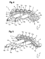
- the pockets 16a, 16b serve to receive in the FIGS. 4 and 5 shown cover-side projections 28a, 28b to form a Walkerumble defining four heating channels 30a to 30d.
- a lower longitudinal guide 32a and an upper longitudinal guide 32b are respectively formed in the pockets 16a, 16b.
- a plurality of parallel channels 34a to 34f, 36a to 36f are arranged laterally of the pockets 16a, 16b, which extend in the longitudinal direction x through the main body 4 except for the outer channel 34a and are open both in the area of the sealing surface 18 and on the rear wall side.
- the outer channel 34a is open only on the sealing surface side and closed at the rear by a wall which is not visible in the figures.
- the channels 34a to 34f, 36a to 36f are arranged in pairs in three planes one above the other and separated by a respective intermediate wall 38a, 38b, 38c, 40a, 40b, 40c from lying in the same horizontal plane channel 34a to 34f, 36a to 36f.
- the intermediate walls 38a, 38b, 38c, 40a, 40b, 40c each extend flush from a rear closure surface 42, 43 in the direction of the sealing surface 18 and are spaced therefrom in the axial direction, wherein due to the inclined position of the sealing surface 18, the intermediate walls 38a, 38b , 38c extends axially in the flow direction and the intermediate walls 40a, 40b, 40c are axially shortened in the flow direction.
- left channels 34a to 34f are formed as a feed line defining feed channels and viewed in the flow direction gradually axially extended, so that starting from the middle feed channel pair with the flow channels 34c, 34d of the upstream inner flow channel 34b axially shortened and the downstream flow channel pair with the flow channels 34e, 34f is axially extended.
- the flow channels 34b to 34f are closed by a closure element, not shown, which has a multiplicity of deflection curves for the end-side connection of two vertically overlapping flow channels 34b with 34c, 34d with 34e.
- the flow path according to the representations in the FIGS. 2 and 3 one below the left pocket 16a arranged inlet channel 46 which extends parallel to the inner long flow channel 34f from the closure surface 42 to the sealing surface 18 and is open on both sides.
- the closure element has a horizontal deflection arc.
- the supply line has the following water supply:
- the water to be heated is guided via the inlet connection 44 in the inner short flow channel 34b, guided in the vertical direction in the region of the closure element in the inner central flow channel 34c, in the region of the sealing surface 18 in a horizontal plane around the partition 38b guided in the outer central flow channel 34d, guided in the region of the closure member in the vertical direction in the outer long flow channel 34e, guided in the region of the sealing surface 18 in the horizontal plane around the intermediate wall 38c in the inner long Vorlaukanal 34f, then in the region of the closure element in guided in the horizontal direction in the inlet channel 46 and finally enters the cover side in the heating section.
- right channels 36a to 36f are formed as a follow-up distance defining trailing channels and viewed in the flow direction gradually shortened axially, so that starting from the middle follower channel pair with the follower channels 36c, 36d the upstream follower channel pair with the follower channels 36a, 36b extends axially and the downstream follower channel pair with the Trailing channels 36e, 36f is shortened axially.
- the overflow channels 36a to 36f are closed by a closure element, not shown, which has a plurality of deflecting curves for the end-side connection of two vertically successive overflow channels 36b to 36c, 36d to 36e.
- the closure element (not shown) has a horizontal deflection arc.
- the overflow section has the following water flow:
- the heating water flows from the heating path on the cover side into the discharge channel 50, flows in the region of the closure element in the horizontal direction in the inner long follow-up channel 36a, in the region of the sealing surface 18 in a horizontal plane around the intermediate wall 40a in the outer long trailing channel 36b, in the region of the closure element in the vertical direction in the outer middle trailing channel 36c, in the region of the sealing surface 18 in the horizontal plane around the intermediate wall 40b in the inner central trailing channel 36d, in the region of the closure member in the vertical direction in the inner short flow channel 36e, then in the region of the sealing surface 18 in the horizontal plane about the intermediate wall 40c in the outer short Vorlaukanal 36f and finally exits through the outlet port 48 from the trailing distance.
- the lid 6 is preferably a one-piece injection molded part and has according to the FIGS. 4 and 5
- the two projections 28a, 28b are formed like a blade and positioned at a lateral distance from each other, the distance of the receiving longitudinal guides 32a, 32b of the main body 4 corresponds. They are connected by a foot section to a transversely extending inner surface 54 and each have a T-shaped head portion 56a, 56b for receiving in each case a heating coil 58a, 58b indicated in FIG.
- the foot sections have two inner and facing concave surfaces 60a, 60b, which extend in the vertical direction z and together with the inner surface 54 each form a deflection section for the two inner heating channels 30b, 30c, which are separated from each other via the main body-side partition wall 22.
- the projections on both sides in each case a plurality of mutually parallel guide webs 62a, 62b to Positional fixing of the heating coils 58a, 58b.
- the heating coils 58a, 58b are U-shaped in each case by a projection 28a, 28b placed and with their free end portions in the region of each cover-side connecting piece 64a to 64d with a in FIG. 1 shown electrical contact element 65a to 65d for energizing the heating coils 58a, 58b electrically connected.
- the connecting pieces 64a to 64d are positioned in a non-numbered cover wall extending above the projections in a horizontal plane and orientated in the vertical direction z, whereby they are freely accessible from below and thus the connection of the heating coils 58a, 58b to the contact elements 65a to 65d is simplified ,
- power electronics not shown, can be screwed directly onto the contact elements 64a to 64d through the connecting pieces 64a to 64d which are oriented in the vertical direction z, as a result of which cables or contact sheets are saved.
- the chambers 66a, 66b, 66c, 68a, 68b, 68c each have an obliquely obliquely to the longitudinal direction x upper chamber surface 69, 71 and an approximately triangular longitudinal section, whereby the chambers 66a, 66b, 66c, 68a, 68b, 68c are open on the bottom side ,
- the inclination of the chamber surfaces 69, 71 is such that the chambers 66a, 66b, 66c, 68a, 68b, 68c are funnel-shaped or conically tapered in a direction away from their opening.
- the cover 6 in each case has a vertical shaft 74, 75.
- the shafts 74, 75 are open on the bottom side and bounded laterally in the transverse direction y by an arc surface 76 of the foot sections of the projections 28a, 28b and a cover wall 78, 79 forming the chambers 66a, 66b, 66c, 68a, 68b, 68c.
- the sealing member 12 is a one-piece injection molded part as in FIGS FIGS. 6 and 7 shown a plate-like geometry and a constant wall thickness. It has a sealing surface 80 for abutment with the sealing surface 18 of the base body 4 and an opposite sealing surface 82 for engagement with the sealing surface 52 of the lid 6. Due to the employment of the parting plane to the horizontal plane or to the Channel longitudinal axes are also the sealing surfaces 80, 82 made at an angle of 45 ° to the horizontal plane.
- the deflection regions 70a, 70b, 70c for the flow channels 34a to 34f and the deflection regions 72a, 72b, 72c for the lagging channels 36a to 36f are arranged in a staircase manner in the vertical edge region. They each have a U-shaped side wall 84, 86, which protrudes with a central portion 88, 90 via the sealing surface 82 facing the lid and with its free end portions 92a, 92b, 94a, 94b on the sealing surface 80 facing the body.
- the middle sections 88, 90 extend in the vertical direction z from the sealing body surface 80 facing the base body and form a common edge region, each with a ceiling-side wall 96, 98 inclined obliquely in the longitudinal direction x.
- the deflecting portions 70a, 70b, 70c, 72a, 72b, 72c are formed closed when viewed rearwardly.
- the deflecting regions 70a, 70b, 70c, 72a, 72b, 72c each form an unnumbered cavity, which is delimited by the inclined wall 96, 98 and an inner deflecting surface 100, 102 formed by the side wall 86, 88.
- the deflection surfaces 100, 102 lie in the vertical plane and are aerodynamically arcuate.
- the inclination of the walls 96, 98 is such that the deflecting portions 70a, 70b, 70c, 72a, 72b, 72c taper rearwardly from their opening in a funnel-shaped or conical manner, whereby in combination with the oblique chamber surfaces 69, 71 a self-centering of the sealing element 8 takes place on the lid 6.
- two rectangular recesses 104a, 104b are arranged side by side in the transverse direction y for establishing a fluid connection between the base body side heating channels 30a to 30d and the cover side deflection sections.
- the recesses 104a, 104b have a same opening cross section as the pockets 16a, 16b and are connected to each other via a taper between diametrically arranged sealing strips 106a, 106b.
- the sealing strips 106a, 106b extend in the assembled state along the base body-side web portion 24 and each have a positioning pin 108a, 108b for immersion in the hole-like depressions 26a, 26b of the web portion 24.
- the sealing element 8 has two rectangular openings 110, 112, which are spaced apart from each other via an edge-downgrading 114.
- the openings 110, 112 serve to introduce the water to be heated from the flow path into the heating section and for discharging the heated water from the heating section in the overrun section. They are like in FIG. 8 shown in the assembled state in the parting plane between the inlet channel 46 and the inlet-side shaft 74 and the drain-side shaft 75 and the drain passage 50 are arranged.
- FIG. 8 shows a longitudinal section in a horizontal plane through the radiator 1, which extends through the middle flow channel pair with the flow channels 34c, 34d, through the middle follower channel pair with the wake channels 36c, 36d and the heating channels 30a to 30d.
- the sealing element 8 is clamped between the main body 4 and the cover 6, which is secured to the base body 4 via the screws 10.
- the middle side wall sections 88, 90 and the horizontal walls 96, 98 of the deflecting regions 70b, 72b, which are not visible in this figure, are accommodated in the chambers 66b, 68b of the cover 6.
- the free side end portions 92a, 92b, 94a, 94b protrude into the flow channels 34c, 34d and the wake channels 36c, 36d and lie flat against opposite side surfaces 116a, 116b of the feed channel pairs 34c, 34d and on opposite side surfaces 118a, 118b of the follower channel pairs 36c, 36d on.
- the deflection of the water in the flow path and the trailing distance already begins in the main body 4 and in the flow channels 34a to 34f and the trailing channels 36a to 34f.
- the projections 28a, 28b are received in the longitudinal guides 32a, 32b and divide the pockets 16a, 16b into two heating channels 30a to 30d, respectively.
- Each projection 28a, 28b is equipped with a heating coil 58a, 58b which extends on both sides of the projection 28a, 28b in the longitudinal direction x and is guided in a U-shape around the head section 56a, 56b, not shown.
- the sealing element 8 For mounting the cover 6 on the base body 4, the sealing element 8 on the base body side with the projections 92a, 92b and 94a, 94b in the leading and trailing channels 34a to 34f and 36a to 36f and with the positioning pins 108a, 108b in the recesses 26a, 26b inserted. Subsequently, the projections 28a, 28b the lid 6 is inserted into the base body 4. In this case, the sealing element 8 is centered on the tapered walls 96, 98 of the deflection regions 70a to 70c and 72a to 72c and the inclined chamber surfaces 69, 71 automatically in or on the lid 6. Thereafter, the cover 6 with the housing 4 on the Screw n10 screwed.
- the flow path and the trailing path are closed at the rear in the region of the closure surfaces 42, 43 via the closure elements, not shown, with the integrated deflecting bends.
- a heating block for an electrically heated water heater for cooking water with a base body in which a plurality of heating channels for defining a heating section, a plurality of flow channels for defining a delay line and a plurality of follow-up channels are designed to define a tracking distance which are open at least on one side, and with at least one lid for one-sided closing of the channels, wherein a sealing element is provided for arranging in a parting plane between the base body and the lid having deflection regions for the end-side connection of adjacent channels, and a sealing element for a such heating block.
Landscapes
- Engineering & Computer Science (AREA)
- Physics & Mathematics (AREA)
- Thermal Sciences (AREA)
- Chemical & Material Sciences (AREA)
- Combustion & Propulsion (AREA)
- Mechanical Engineering (AREA)
- General Engineering & Computer Science (AREA)
- Bidet-Like Cleaning Device And Other Flush Toilet Accessories (AREA)
- Resistance Heating (AREA)
Abstract
Description
- Die Erfindung betrifft einen Heizblock für einen elektrisch beheizten Durchlauferhitzer in Blankdrahttechnik zum Erhitzen von Wasser nach dem Oberbegriff des Patentanspruchs 1, mit einem Grundkörper, in dem eine Vielzahl von Heizkanälen zur Definierung einer Heizstrecke, eine Vielzahl von Vorlaufkanälen zur Definierung einer Vorlaufstrecke und eine Vielzahl von Nachlaufkanälen zur Definierung einer Nachlaufstrecke ausgebildet sind, die zumindest einseitig geöffnet sind, und mit zumindest einem Deckel zum einseitigen Verschließen der Kanäle, sowie ein Dichtungselement für einen derartigen Heizblock zur Anordnung in einer Trennebene zwischen einem wasserführenden Grundkörper und einem Deckel zum Verschließen von in dem Grundkörper verlaufenden wasserführenden Kanälen.
- Ein derartiger Heizblock ist z. B. in dem deutschen Gebrauchsmuster
DE 201 08 117 U 1 gezeigt. Dieser ist für einen elektrischen Durchlauferhitzer in Blankdrahttechnik vorgesehen und hat ein dreiteiliges Gehäuse, das von einem Grundkörper und zwei Deckeln gebildet wird. In dem Grundkörper sind parallele Heiz-, Vorlauf- und Nachlaufkanäle ausgebildet, die jeweils beidseitig aus dem Grundkörper heraustreten. Die Kanäle sind endseitig über die Deckel verschließbar, wobei zur Reduzierung einer axialen Baulänge des Heizblockes an den Deckeln Umlenkbereiche zum Verbinden benachbarter Kanäle angeformt sind, die abschnittsweise in die Kanäle und somit in den Grundkörper hineinragen. Zum Abdichten des Heizblocks ist in einer Trennebene zwischen dem Grundkörper und dem jeweiligen Deckel jeweils ein Dichtungselement vorgesehen. Nachteilig an diesem Heizblock ist die aufwendige Fertigung der Deckel, da bei deren Herstellung neben strukturmechanisch notwendigen Versteifungsrippen, Befestigungsflanschen und drgl. auch die Umlenkbereiche mit auszubilden sind - Aufgabe der Erfindung ist es, einen Heizblock für einen elektrischen Durchlauferhitzer in Blankdrahttechnik, der die vorgenannten Nachteile beseitigt und dessen Fertigungssowie Montageaufwand reduziert ist, sowie ein Dichtungselement für einen derartigen Heizblock zu schaffen.
- Diese Aufgabe wird gelöst durch einen Heizblock mit den Merkmalen des Patentanspruchs 1 und durch ein Dichtungselement mit den Merkmalen des Patentanspruch 11. Vorteilhafte Aus- und Weiterbildungen, welche einzeln oder in Kombination miteinander ersetzbar sind, sind Gegenstand der jeweils abhängigen Ansprüche.
- Ein erfindungsgemäßer Heizblock für einen elektrisch beheizten Durchlauferhitzer in Blankdrahttechnik zum Erhitzen von Wasser hat einen Grundkörper, in dem eine Vielzahl von Heizkanälen zur Definierung einer Heizstrecke, eine Vielzahl von Vorlaufkanälen zur Definierung einer Vorlaufstrecke und eine Vielzahl von Nachlaufkanälen zur Definierung einer Nachlaufstrecke ausgebildet sind, die zumindest einseitig geöffnet sind, und zumindest einen Deckel zum Verschließen der Kanäle. Erfindungsgemäß ist ein Dichtungselement zum Anordnen in einer Trennebene zwischen dem Gehäuse und dem Deckel vorgesehen, das Umlenkbereiche zum endseitigen Verbinden von benachbarten Kanälen aufweist. Die erfindungsgemäße Lösung erlaubt die fertigungstechnisch einfache Herstellung des Deckels und des Grundkörpers, da die Umlenkbereiche in das Dichtungselement integriert sind und somit nicht mehr an dem Deckel und dem Grundkörper angeformt sein müssen. Der Deckel und der Grundkörper können somit bequem bspw. durch ein Spritzgießverfahren hergestellt werden.
- Die axiale Baulänge des Heizblocks lässt sich reduzieren, wenn die Umlenkbereiche im montierten Zustand des Heizblocks sowohl in die Kanäle als auch in Kammern des Deckels eintauchen. Dies ist bei einem Ausführungsbeispiel dadurch realisiert, dass sich die Umlenkbereiche über eine grundkörperzugewandte Dichtfläche und eine entgegengesetzte deckelzugewandte Dichtfläche des Dichtungselements hinaus erstrecken. Zusätzlich zur Verkürzung der axialen Baulänge erfolgt durch die vorstehenden deckelzugewandten Umlenkbereiche insbesondere eine Selbstzentrierung des Dichtungselements am Deckel.
- Die Selbstzentrierung lässt sich unterstützen, wenn wie bei einem Ausführungsbeispiel Wandungen der Umlenkbereiche und Deckelflächen der Deckel zur Aufnahme der Umlenkbereiche schräg bzw. konisch ausgebildet sind, so dass bei einer Gleitverbindung zwischen den Wandungen und den Deckelflächen Einführschrägen gebildet werden.
- Die axiale Baulänge des Heizblocks lässt sich weiter reduzieren, wenn eine Umlenkung des Wassers bereits in den Kanälen beginnt. Hierzu sind bei einem Ausführungsbeispiel Zwischenwände zur Bildung der Vorlaufkanäle und Nachlaufkanäle von der Trennebene zurückgestuft.
- Die Länge der Vorlaufstrecke und die Länge der Nachlaufstrecke ist bevorzugterweise an die maximale Heizleistung angepasst, wobei die benötigte Vor- und Nachlaufstrecke abhängig von der Spannung zwischen Heizwendel und Erde, den Wassertemperaturen in der Vor- und Nachlaufstrecke sowie vom zu erwärmenden Wasser ist, dessen Leitwert einen definierten Grenzwert nicht überschreiten darf. Da die Länge der Vorlaufstrecke und die der Nachlaufstrecke dabei je nach der Heizleistung wesentlich länger als die Länge der Heizstrecke sein kann ,sind die Vorlaufkanäle und die Nachlaufkanäle bei einem Ausführungsbeispiel mit einer hohen Heizleistung in vertikaler Richtung im wesentlichen jeweils paarweise stufenförmig übereinander angeordnet. Entsprechend sind bei diesem Ausführungsbeispiel die den jeweiligen Kanälen zugeordneten Umlenkbereiche stufenartig übereinander angeordnet.
- Bei einem besonders kompakten Ausführungsbeispiel sind in Strömungsrichtung Betrachtet die Vorlaufkanäle axial verkürzt und die Nachlaufkanäle axiale verlängert. Hierdurch verläuft die Trennebene nicht senkrecht zu den Kanälen, sondern ist zu diesen um einen Winkel ungleich 90°, beispielsweise 45°, angestellt. Um das Dichtungselement mit einer konstanten Dicke bzw. einen konstanten Abstand zwischen seinen Dichtflächen ausführen zu können, sind bei diesem Ausführungsbeispiel die Umlenkbereiche entsprechend der Anstellung der Trennebene zu den Kanälen zu den Dichtflächen um jeweils einen Winkel ungleich 90° angestellt.
- Das Dichtungselement ist besonders einfach herstellbar, wenn es nur für einen Teil der Kanäle die Umlenkbereiche aufweist. Bei einem bevorzugten Ausführungsbeispiel sind an dem Dichtungselement lediglich die Umlenkbereiche für die Vorlaufkanäle und die Umlenkbereiche für die Nachlaufkanäle angeformt. Umlenkabschnitte für die Heizkanäle sind dabei im Deckel ausgebildet. Dabei können aufgrund der Schrägstellung der Trennebene insbesondere bei spritzgusstechnischer Fertigung deckelseitige Kammern zur Aufnahme der Umlenkbereiche und der Umlenkabschnitte günstig in Hochrichtung z entformt werden.
- Bei einem Ausführungsbeispiel ist der Grundkörper zumindest im Bereich der Heizkanäle bzw. der Heizstrecke rückwandseitig geschlossen und mit integrierten rückwandseitigen Umlenkungen ausgebildet. Hierdurch wird die Montage des Heizblocks weiter vereinfacht, da zumindest die Heizkanäle nur einseitig über den Deckel zu schließen sind. Die Vorlauf- und Nachlaufkanäle werden rückseitig bevorzugterweise über ein entsprechendes separates Verschlusselement mit integrierten Umlenkbögen verschlossen. Es ist jedoch auch vorstellbar, zum rückseitigen Umlenken des Wassers in den Vorlauf- und Nachlaufkanälen das erfindungsgemäße Dichtungselement mit den integrierten Umlenkbereichen zu verwenden. Ebenso können die Heizkanäle rückseitig geöffnet sein und das Wasser über ein Verschlusselement mit integrierten Umlenkbögen oder mittels des erfindungsgemäßen Dichtungselements mit den integrierten Umlenkbereichen umgelenkt werden.
- Die Montage des Heizblocks lässt sich vereinfachen, wenn der Deckel zumindest einen wandartigen Vorsprung zur Bildung benachbarter Heizkanäle aufweist, da hierdurch bei der Montage des Heizkörpers durch den zumindest einen Vorsprung eine Vorpositionierung des Deckels zum Grundkörper erfolgt.
- Die Montage lässt sich weiter vereinfachen, wenn an dem Vorsprung ein Heizelement für beide Heizkanäle befestigbar ist und wenn der Deckel Anschlussstutzen zur Aufnahme elektrischer Kontaktelemente zur Bestromung des Heizelementes aufweist. Hierdurch kann die Montage des Heizelements außerhalb des Grundkörpers erfolgen, so dass das zumindest eine Heizelement automatisch beim Verschließen des Gehäuses bzw. beim Positionieren des Deckels in den Grundkörper eingeführt wird. Ein Durchfädeln des Heizelements durch die Kanäle im Grundkörper entfällt. Ferner wird beim Öffnen des Gehäuses durch das Entfernen des Deckels das Heizelement automatisch aus dem Grundkörper entnommen, was dessen Austausch und Wartung wesentlich vereinfacht bzw. komfortabler macht.
- Ein erfindungsgemäßes Dichtungselement für einen Heizblock eines elektrischen Durchlauferhitzers zum Erhitzen von Wasser zur Anordnung in einer Trennebene zwischen einem wasserführenden Grundkörper und einem Deckel zum Verschließen von in dem Grundkörper verlaufenden wasserführenden Kanälen hat zumindest einen Umlenkbereich zum endseitigen Verbinden von benachbarten Kanälen. Ein derartiges Dichtungselement ist fertigungstechnisch einfach herstellbar, beispielsweise durch ein Spritzgießverfahren, vereinfacht die Herstellung des Grundkörpers und des Deckels und ermöglicht eine kompakte Ausführung des Heizblocks.
- Die vorliegende Erfindung eignet sich insbesondere zur Bereitstellung eines kompakten Heizblocks für einen elektrischen Durchlauferhitzer in Blankdrahttechnik im häuslichen Bereich, der schnell und einfach herzustellen ist und einen einfachen Austausch eines defekten Heizelementes erlaubt.
- Sonstige vorteilhafte Ausführungsbeispiele der Erfindung sind Gegenstand weiterer Unteransprüche.
- Im Folgenden werden bevorzugte Ausführungsbeispiele der Erfindung anhand schematischer Darstellungen näher erläutert. Es zeigen:
- Figur 1
- einen teilweisen Längsschnitt entlang einer Vertikalebene durch einen erfindungsgemäßen Heizblock,
- Figur 2
- eine perspektivische Frontansicht eines Grundkörpers des Heizblocks aus
Figur 1 , - Figur 3
- eine perspektivische Rückansicht des Grundkörpers aus
Figur 2 , - Figur 4
- eine perspektivische Draufsicht auf einen Dichtungsbereich eines Deckels des Heizblocks aus
Figur 1 , - Figur 5
- eine perspektivische Draufsicht auf den Deckel aus
Figur 4 mit einem installierten Dichtungselement ausFigur 1 , - Figur 6
- eine Draufsicht auf eine grundkörperzugewandte Dichtungsfläche des Dichtungselements aus
Figur 5 , - Figur 7
- eine Draufsicht auf eine deckelzugewandte Dichtungsfläche des Dichtungselements aus
Figur 6 , und - Figur 8
- einen Längsschnitt entlang einer Horizontalebene durch den erfindungsgemäßen Heizblock aus
Figur 1 . - Eingangs ei erwähnt, dass sich die Orientierungen wie vertikale Richtung, Hochrichtung, Horizontalebene und drgl. auf die in den
Figuren 1 bis 8 gezeigte Ausrichtung und nicht auf die Einbaulage des gezeigten Heizblocks beziehen. - Gemäß
Figur 1 hat ein erfindungsgemäßer Heizblock 1 für einen elektrischen Durchlauferhitzer in Blankdrahttechnik zum Erhitzen von Wasser ein Gehäuse 2, das einen von dem zu erwärmenden Wasser durchströmten Grundkörper 4 und einen Deckel 6 zum einseitigen Verschließen des Gehäuses 4 aufweist. Zum Abdichten des Gehäuses 4 ist in einer Trennebene zwischen dem Grundkörper 2 und dem Deckel 6 ein Dichtungselement 8 angeordnet. Die Trennebene ist um einen Winkel ungleich 90° zur Längsrichtung x des Gehäuses 2 angestellt. Bei dem hier gezeigten Ausführungsbeispiel ist die Trennebene um einen Winkel von 45° Längsrichtung x in einer Horizontalebene angestellt. Der Deckel 6 ist über eine Vielzahl von Schrauben 10, die durch jeweils eine deckelseitige Durchgangsbohrung 12 geführt und mit einer grundkörperseitigen Innengewindebohrung 14 im Wirkeingriff stehen lösbar mit dem Grundkörper 4 verbunden. - Der Grundkörper 4 ist ein einteiliges Spritzgussteil und weist wie in den
Figuren 2 und 3 gezeigt zwei Taschen 16a, 16b auf, die im Bereich einer stirnseitigen Dichtfläche 18 bzw. der Trennebene geöffnet und im Bereich einer von der Dichtfläche 18 entfernt liegenden Rückwand 20 geschlossen sind. Die Taschen 16a, 16b sind über eine Trennwand 22 voneinander begrenzt, die sich von der Rückwand 18 in Richtung der Trennebene erstreckt und einen Stegabschnitt 24 der Dichtfläche 18 bildet, in dem zwei bohrungsartige Vertiefungen 26a, 26b ausgebildet sind. Die Taschen 16a, 16b dienen zur Aufnahme von in denFiguren 4 und 5 gezeigten deckelseitigen Vorsprüngen 28a, 28b zur Bildung von eine Heizstrecke definierenden vier Heizkanälen 30a bis 30d. Zur Aufnahme der Vorsprünge 28a, 28b und zum seitlichen Abdichten der Heizkanäle 30a bis 30d gegeneinander ist in den Taschen 16a, 16b jeweils eine gemäß der Darstellung untere Längsführung 32a und eine obere Längsführung 32b ausgebildet. - Seitlich der Taschen 16a, 16b ist eine Vielzahl von parallelen Kanälen 34a bis 34f, 36a bis 36f angeordnet, die sich bis auf den äußeren Kanal 34a in Längsrichtung x durch den Grundkörper 4 erstrecken und sowohl im Bereich der Dichtfläche 18 als auch rückwandseitig geöffnet sind. Der äußere Kanal 34a ist nur dichtflächenseitig geöffnet und rückwärtig durch eine in den Figuren nicht sichtbare Wand verschlossen. Die Kanäle 34a bis 34f, 36a bis 36f sind paarweise in drei Ebenen übereinander angeordnet und über jeweils eine Zwischenwand 38a, 38b, 38c, 40a, 40b, 40c von dem in der gleichen Horizontalebene liegenden Kanal 34a bis 34f, 36a bis 36f getrennt. Die Zwischenwände 38a, 38b, 38c, 40a, 40b, 40c erstrecken sich jeweils bündig von einer rückwärtigen Verschlussfläche 42, 43 in Richtung der Dichtfläche 18 und sind von dieser in axialer Richtung beabstandet, wobei aufgrund der Schrägstellung der Dichtfläche 18 die Zwischenwände 38a, 38b, 38c in Strömungsrichtung axial verlängert und die Zwischenwände 40a, 40b, 40c in Strömungsrichtung axial verkürzt sind.
- Die gemäß der Darstellung bzw. Frontalansicht in
Figur 2 linken Kanäle 34a bis 34f sind als eine Vorlaustrecke definierende Vorlaufkanäle ausgebildet und in Strömungsrichtung betrachtet stufenweise axial verlängert, so dass ausgehend von dem mittleren Vorlaufkanalpaar mit den Vorlaufkanälen 34c, 34d der stromaufwärtige innere Vorlaufkanal 34b axial verkürzt und das stromabwärtige Vorlaufkanalpaar mit den Vorlaufkanälen 34e, 34f axial verlängert ist. Die Einleitung des zu erwärmenden Wassers erfolgt über einen Einlassstutzen 44 im Bereich des kurzen inneren Vorlaufkanals 34b, dessen sich zwischen dem Einlassstutzen 44 und dem Deckel 8 erstreckender Kanalabschnitt mit dem äußeren sacklochartigen Vorlaufkanal 34a eine Luftkammer zur Aufnahme von Druckschwankungen im System bildet. Im Bereich der rückwärtigen Verschlussfläche 42 sind die Vorlaufkanäle 34b bis 34f über ein nicht gezeigtes Verschlusselement verschlossen, welches eine Vielzahl von Umlenkbögen zum endseitigen Verbinden von jeweils zwei in vertikaler Richtung übereinander liegenden Vorlaufkanälen 34b mit 34c, 34d mit 34e aufweist. - Zusätzlich zu dem kurzen, dem mittleren und dem langen Vorlaufkanalpaar weist die Vorlaufstrecke gemäß den Darstellungen in den
Figuren 2 und 3 einen unterhalb der linken Tasche 16a angeordneten Zulaufkanal 46 auf, der sich parallel zu dem inneren langen Vorlaufkanal 34f von der Verschlussfläche 42 zur Dichtfläche 18 erstreckt und beidseits geöffnet ist. Zur Herstellung einer Fluidverbindung des inneren langen Vorlaufkanals 34f mit dem Zulaufkanal 46 weist das nicht gezeigte Verschlusselement einen horizontalen Umlenkbogen auf. - Die Vorlaufstrecke weist folgende Wasserführung auf: Das zu erhitzende Wasser wird über den Einlaufstutzen 44 in den inneren kurzen Vorlaufkanal 34b geführt, im Bereich des Verschlusselements in vertikaler Richtung in den inneren mittleren Vorlaufkanal 34c geführt, im Bereich der Dichtfläche 18 in horizontaler Ebene um die Zwischenwand 38b in den äußeren mittleren Vorlaufkanal 34d geführt, im Bereich des Verschlusselements in vertikaler Richtung in den äußeren langen Vorlaufkanal 34e geführt, im Bereich der Dichtfläche 18 in horizontaler Ebene um die Zwischenwand 38c in den inneren langen Vorlaukanal 34f geführt, dann im Bereich des Verschlusselements in horizontaler Richtung in den Zulaufkanal 46 geführt und tritt abschließend deckelseitig in die Heizstrecke ein.
- Die gemäß der Darstellung in
Figur 2 rechten Kanäle 36a bis 36f sind als eine Nachlaufstrecke definierende Nachlaufkanäle ausgebildet und in Strömungsrichtung betrachtet stufenweise axial verkürzt, so dass ausgehend von dem mittleren Nachlaufkanalpaar mit den Nachlaufkanälen 36c, 36d das stromaufwärtige Nachlaufkanalpaar mit den Nachlaufkanälen 36a, 36b axial verlängert und das stromabwärtige Nachlaufkanalpaar mit den Nachlaufkanälen 36e, 36f axial verkürzt ist. Die Entnahme des erwärmenden Wassers erfolgt über einen Auslassstutzen 48 im Bereich des kurzen Nachlaufkanalpaars. Im Bereich der rückwärtigen Verschlussfläche 43 sind die Nachlaufkanäle 36a bis 36f über ein nicht gezeigtes Verschlusselement verschlossen, welches eine Vielzahl von Umlenkbögen zum endseitigen Verbinden von jeweils zwei in vertikaler Richtung übereinander liegenden Nachlaufkanälen 36b mit 36c,36d mit 36e aufweist. - Zusätzlich zu dem langen, dem mittleren und dem kurzen Nachlaufkanalpaar 36a bis 36f weist die Nachlaufstrecke gemäß den Darstellungen in den
Figuren 2 und 3 einen unterhalb der rechten Tasche 16b angeordneten Ablaufkanal 50 auf, der sich parallel zu dem inneren langen Nachlaufkanal 36a von der Verschlussfläche 43 zur Dichtfläche 16b erstreckt und beidseits geöffnet ist. Zur Herstellung einer Fluidverbindung des Ablaufkanals 50 mit dem inneren langen Nachlaufkanal 36a weist das nicht gezeigte Verschlusselement einen horizontalen Umlenkbogen auf. - Die Nachlaufstrecke weist folgende Wasserführung auf: Das erhitzende Wasser fließt aus der Heizstrecke deckelseitig in den Ablaufkanal 50 ab, strömt im Bereich des Verschlusselements in horizontaler Richtung in den inneren langen Nachlaufkanal 36a, im Bereich der Dichtfläche 18 in horizontaler Ebene um die Zwischenwand 40a in den äußeren langen Nachlaufkanal 36b, im Bereich des Verschlusselements in vertikaler Richtung in den äußeren mittleren Nachlaufkanal 36c, im Bereich der Dichtfläche 18 in horizontaler Ebene um die Zwischenwand 40b in den inneren mittleren Nachlaufkanal 36d, im Bereich des Verschlusselements in vertikaler Richtung in den inneren kurzen Vorlaufkanal 36e, dann im Bereich der Dichtfläche 18 in horizontaler Ebene um die Zwischenwand 40c in den äußeren kurzen Vorlaukanal 36f und tritt abschließend über den Auslassstutzen 48 aus der Nachlaufstrecke aus.
- Der Deckel 6 ist vorzugsweise ein einteiliges Spritzgussteil und hat gemäß den
Figuren 4 und 5 eine entsprechend der Anstellung der Trennebene eine um 45° zur Horizontalebene angestellte Dichtfläche 52 zur Anlage des Dichtungselements 8. Die beiden Vorsprünge 28a, 28b sind klingenartig ausgebildet und in einem seitlichen Abstand voneinander positioniert, der dem Abstand der sie aufnehmenden Längsführungen 32a, 32b des Grundkörpers 4 entspricht. Sie sind mit einem Fußabschnitt an einer sich in Querrichtung erstreckenden Innenfläche 54 angebunden und weisen jeweils einen T-förmigen Kopfabschnitt 56a, 56b zur Aufnahme jeweils einer in Figur 9 angedeuteten Heizwendel 58a, 58b auf. - Die Fußabschnitte weisen zwei innenliegende und zueinander zugewandte Konkavflächen 60a, 60b auf, die sich in vertikaler Richtung z erstrecken und zusammen mit der Innenfläche 54 jeweils einen Umlenkabschnitt für die beiden innenliegenden Heizkanäle 30b, 30c bilden, die über die grundkörperseitige Trennwand 22 voneinander getrennt sind.
- Zusätzlich zu den T-förmigen Kopfabschnitten 56a, 56b weisen die Vorsprünge beidseits jeweils eine Vielzahl von parallel zueinander verlaufenden Führungsstegen 62a, 62b zur Lagefixierung der Heizwendeln 58a, 58b auf. Die Heizwendeln 58a, 58b werden U-förmig um jeweils einen Vorsprung 28a, 28b gelegt und mit ihren freien Endabschnitten im Bereich jeweils eines deckelseitigen Anschlussstutzens 64a bis 64d mit einem in
Figur 1 gezeigten elektrischen Kontaktelement 65a bis 65d zur Bestromung der Heizwendeln 58a, 58b elektrisch verbunden. - Die Anschlussstutzen 64a bis 64d sind in einer oberhalb der Vorsprünge in einer horizontalen Ebene verlaufenden nicht bezifferten Deckelwandung positioniert und in Hochrichtung z orientiert, wodurch diese von unten frei zugänglich sind und somit der Anschluss der Heizwendeln 58a, 58b an den Kontaktelementen 65a bis 65d vereinfacht ist. Zudem kann durch die in Hochrichtung z orientierten Anschlussstutzen 64a bis 64d eine nicht gezeigte Leistungselektronik direkt auf die Kontaktelemente 64a bis 64d geschraubt werden, wodurch Kabel oder Kontaktbleche eingespart werden.
- Seitlich der Vorsprünge 28a, 28b sind jeweils in vertikaler Richtung übereinander stufenförmig versetzt drei Kammern bzw. Kassetten 66a, 66b, 66c, 68a, 68b, 68c zur Aufnahme jeweils eines vorlaufkanalseitigen und nachlaufkanalseitigen Umlenkbereichs 70a, 70b, 70c, 72a, 72b, 72c des Dichtungselements 8 angeordnet. Die Kammern 66a, 66b, 66c, 68a, 68b, 68c haben jeweils eine schräg zur Längsrichtung x angestellte obere Kammerfläche 69, 71 und einen in etwa dreieckförmigen Längsschnitt, wodurch die Kammern 66a, 66b, 66c, 68a, 68b, 68c bodenseitig geöffnet sind. Die Schrägstellung der Kammerflächen 69, 71 ist derart, dass die Kammern 66a, 66b, 66c, 68a, 68b, 68c in eine Richtung weg von ihrer Öffnung trichterförmig bzw. konisch verjüngt ausgebildet sind. Zwischen den Vorsprüngen 28a, 28b und den Kammern 66a, 66b, 66c, 68a, 68b, 68c weist der Deckel 6 jeweils einen vertikalen Schacht 74, 75 auf. Die Schächte 74, 75 sind bodenseitig geöffnet und seitlich in Querrichtung y über jeweils eine Bogenfläche 76 der Fußabschnitte der Vorsprünge 28a, 28b und einer die Kammern 66a, 66b, 66c, 68a, 68b, 68c bildenden Deckelwandung 78, 79 begrenzt.
- Das Dichtungselement 12 ist ein einteiliges Spritzgussteil mit wie in den
Figuren 6 und 7 gezeigt einer plattenartigen Geometrie und einer konstanten Wandstärke. Es hat eine Dichtungsfläche 80 zur Anlage an der Dichtfläche 18 des Grundkörpers 4 und eine entgegengesetzte Dichtungsfläche 82 zur Anlage an der Dichtfläche 52 des Deckels 6. Aufgrund der Anstellung der Trennebene zur Horizontalebene bzw. zu den Kanallängsachsen sind ebenfalls die Dichtungsflächen 80, 82 um einen Winkel von 45° zur Horizontalebene angestellt. - Die Umlenkbereiche 70a, 70b, 70c für die Vorlaufkanäle 34a bis 34f und die Umlenkbereiche 72a, 72b, 72c für die Nachlaufkanäle 36a bis 36f sind im vertikalen Randbereich treppenartig angeordnet. Sie haben jeweils eine U-förmige Seitenwandung 84, 86, die mit einem mittleren Abschnitt 88, 90 über die deckelzugewandte Dichtungsfläche 82 und mit ihren freien Endabschnitten 92a, 92b, 94a, 94b über die grundkörperzugewandte Dichtungsfläche 80 hinausragt. Die mittleren Abschnitte 88, 90 erstrecken sich in vertikaler Richtung z von der grundkörperzugewandten Dichtungsfläche 80 und bildet mit jeweils einer in Längsrichtung x schräg angestellten deckenseitigen Wandung 96, 98 einen gemeinsamen Kantenbereich. Somit sind die Umlenkbereiche 70a, 70b, 70c, 72a, 72b, 72c bei rückwärtiger Betrachtung geschlossen ausgebildet. Bei frontaler Betrachtung bilden die Umlenkbereiche 70a, 70b, 70c, 72a, 72b, 72c jeweils einen nicht bezifferten Hohlraum, der von der schräg angestellten Wandung 96, 98 und einer von der Seitenwandung 86, 88 gebildeten innenliegenden Umlenkfläche 100, 102 begrenzt wird. Die Umlenkflächen 100, 102 liegen in der Vertikalebene und sind strömungsgünstig bogenförmig ausgebildet. Die Schrägstellung der Wandungen 96, 98 ist derart, dass sich die Umlenkbereiche 70a, 70b, 70c, 72a, 72b, 72c ausgehend von ihrer Öffnung rückwärtig trichterförmig bzw. konisch verjüngen, wodurch in Kombination mit den schrägen Kammerflächen 69, 71 eine Selbstzentrierung des Dichtungselements 8 am Deckel 6 erfolgt.
- Zwischen den Umlenkbereichen 70a, 70b, 70c und 72a, 72b, 72c sind zwei rechteckige Ausnehmungen 104a, 104b zur Herstellung einer Fluidverbindung zwischen den grundkörperseitigen Heizkanälen 30a bis 30d und den deckelseitigen Umlenkabschnitten nebeneinander in Querrichtung y angeordnet. Die Ausnehmungen 104a, 104b weisen einen gleichen Öffnungsquerschnitt wie die Taschen 16a, 16b auf und sind über eine Verjüngung zwischen diametral angeordneten Dichtungsstreifen 106a, 106b miteinander verbunden. Die Dichtungsstreifen 106a, 106b verlaufen im montieren Zustand entlang des grundkörperseitigen Stegabschnitts 24 und weisen jeweils einen Positionierzapfen 108a, 108b zum Eintauchen in die bohrungsartigen Vertiefungen 26a, 26b des Stegabschnitts 24 auf.
- In vertikaler Richtung z unterhalb der Ausnehmungen 104a, 104b weist das Dichtungselement 8 zwei rechteckige Durchbrüche 110, 112 auf, die über eine randseitige Zurückstufung 114 voneinander beabstandet sind. Die Durchbrüche 110, 112 dienen zum Einleiten des zu erwärmenden Wassers aus der Vorlaufstrecke in die Heizstrecke und zum Abführen des erwärmten Wassers aus der Heizstrecke in die Nachlaufstrecke. Sie sind wie in
Figur 8 gezeigt im montierten Zustand in der Trennebene zwischen dem Zulaufkanal 46 und dem zulaufseitigen Schacht 74 bzw. dem ablaufseitigen Schacht 75 und dem Ablaufkanal 50 angeordnet. -
Figur 8 zeigt einen Längsschnitt in einer horizontalen Ebene durch den Heizkörper 1, die sich durch das mittlere Vorlaufkanalpaar mit den Vorlaufkanälen 34c, 34d, durch das mittlere Nachlaufkanalpaar mit den Nachlaufkanälen 36c, 36d und den Heizkanälen 30a bis 30d erstreckt. Das Dichtungselement 8 ist zwischen dem Grundkörper 4 und dem Deckel 6 eingespannt, der über die Schrauben 10 an dem Grundkörper 4 gesichert ist. Die mittleren Seitenwandungsabschnitte 88, 90 und die in dieser Figur nicht sichtbaren horizontalen Wandungen 96, 98 der Umlenkbereiche 70b, 72b, sind in den Kammern 66b, 68b des Deckels 6 aufgenommen. Die freien Seitenendabschnitte 92a, 92b, 94a, 94b ragen in die Vorlaufkanäle 34c, 34d und die Nachlaufkanäle 36c, 36d hinein und liegen flächig dichtend an gegenüberliegenden Seitenflächen 116a, 116b der Vorlaufkanalpaare 34c, 34d und an gegenüberliegenden Seitenflächen 118a, 118b der Nachlaufkanalpaare 36c, 36d an. Somit beginnt die Umlenkung des Wassers in der Vorlaufstrecke und der Nachlaufstrecke bereits in dem Grundkörper 4 bzw. in den Vorlaufkanälen 34a bis 34f und den Nachlaufkanälen 36a bis 34f. - Die Vorsprünge 28a, 28b sind in den Längsführungen 32a, 32b aufgenommen und unterteilen die Taschen 16a, 16b in jeweils zwei Heizkanäle 30a bis 30d. Jeder Vorsprung 28a, 28b ist mit einer Heizwendel 58a, 58b bestückt, die sich beidseits des Vorsprungs 28a, 28b in Längsrichtung x erstreckt und U-förmig um den nicht gezeigten Kopfabschnitt 56a, 56b geführt ist.
- Zur Montage des Deckels 6 an dem Grundkörper 4 wird das Dichtungselement 8 grundkörperseitig mit den Vorsprüngen 92a, 92b und 94a, 94b in die Vor- und Nachlaufkanäle 34a bis 34f bzw. 36a bis 36f sowie mit den Positionierzapfen 108a, 108b in die Vertiefungen 26a, 26b eingelegt. Anschließend werden die Vorsprünge 28a, 28b des Deckels 6 in den Grundkörper 4 eingeschoben. Dabei zentriert sich das Dichtungselement 8 über die konisch zulaufenden Wandungen 96, 98 der Umlenkbereiche 70a bis 70c bzw. 72a bis 72c sowie den schrägen Kammerflächen 69, 71 selbsttätig im bzw. am Deckel 6. Danach wird der Deckel 6 mit dem Gehäuse 4 über die Schraube n10 verschraubt.
- Die Vorlaufstrecke und Nachlaufstrecke werden rückwärtig im Bereich der Verschlussflächen 42, 43 über die nicht dargestellten Verschlusselemente mit den integrierten Umlenkbögen verschlossen.
- Offenbart ist ein Heizblock für einen elektrisch beheizten Durchlauferhitzer in Blankdrahttechnik zum Erhitzen von Wasser, mit einem Grundkörper, in dem eine Vielzahl von Heizkanälen zur Definierung einer Heizstrecke, eine Vielzahl von Vorlaufkanälen zur Definierung einer Vorlaufstrecke und eine Vielzahl von Nachlaufkanälen zur Definierung einer Nachlaufstrecke ausgebildet sind, die zumindest einseitig geöffnet sind, und mit zumindest einem Deckel zum einseitigen Verschließen der Kanäle, wobei ein Dichtungselement zum Anordnen in einer Trennebene zwischen dem Grundkörper und dem Deckel vorgesehen ist, das Umlenkbereiche zum endseitigen Verbinden von benachbarten Kanälen aufweist, sowie ein Dichtungselement für einen derartigen Heizblock.
-
- 1
- Heizblock
- 2
- Gehäuse
- 4
- Grundkörper
- 6
- Deckel
- 8
- Dichtungselement
- 10
- Schraube
- 12
- Durchgangsbohrung
- 14
- Innengewindebohrung
- 16a, 16b
- Tasche
- 18
- Dichtfläche
- 20
- Rückwand
- 22
- Trennwand
- 24
- Stegabschnitt
- 26a, b
- Vertiefungen
- 28a, b
- Vorsprung
- 30a, b, c, d
- Heizkanal
- 32a,b
- Längsführung
- 34a, b, c, d, e, f
- Vorlaufkanal
- 36a, b, c, d, e, f
- Nachlaufkanal
- 38a, b, c
- Zwischenwand
- 40a, b, c
- Zwischenwand
- 42
- Verschlussfläche
- 43
- Verschlussfläche
- 44
- Einlassstutzen
- 46
- Zulaufkanal
- 48
- Auslassstutzen
- 50
- Ablaufkanal
- 52
- Dichtfläche
- 54
- Innenfläche
- 56a, b
- Kopfabschnitt
- 58a, b
- Heizwendel
- 60a, b
- Konkavfläche
- 62a, b
- Führungssteg
- 64a, b, c, d
- Anschlussstutzen
- 65a, b, c, d
- Kontaktelement
- 66a, b, c
- Kammer
- 68a, b, c
- Kammer
- 69
- Kammerfläche
- 70a, b, c
- Umlenkbereich
- 71
- Kammerfläche
- 72a, b, c
- Umlenkbereich
- 74
- Schacht
- 75
- Schacht
- 76
- Bogenfläche
- 78
- Deckelwandung
- 79
- Deckelwandung
- 80
- Dichtungsfläche
- 82
- Dichtungsfläche
- 84
- Seitenwandung
- 86
- Seitenwandung
- 88
- mittlerer Abschnitt
- 90
- mittlerer Abschnitt
- 92a, b
- Endabschnitt
- 94a, b
- Endabschnitt
- 96
- Wandung
- 98
- Wandung
- 100
- Umlenkfläche
- 102
- Umlenkfläche
- 104a, b
- Ausnehmungen
- 106a, b
- Dichtungsstreifen
- 108a, b
- Positionierzapfen
- 110
- Durchbruch
- 112
- Durchbruch
- 114
- Zurückstufung
- 116a, 116b
- Seitenfläche
- 118a, 118b
- Seitenfläche
Claims (11)
- Heizblock (1) für einen elektrisch beheizten Durchlauferhitzer in Blankdrahttechnik zum Erhitzen von Wasser, mit einem Grundkörper (4), in dem eine Vielzahl von Heizkanälen (30a bis 30d) zur Definierung einer Heizstrecke, eine Vielzahl von Vorlaufkanälen (34a bis 34f) zur Definierung einer Vorlaufstrecke und eine Vielzahl von Nachlaufkanälen (36a bis 36f) zur Definierung einer Nachlaufstrecke ausgebildet sind, die zumindest einseitig geöffnet sind, und mit zumindest einem Deckel (6) zum einseitigen Verschließen der Kanäle (34a bis 34f, 36a bis 36f), gekennzeichnet durch ein Dichtungselement (8) zum Anordnen in einer Trennebene zwischen dem Grundkörper (4) und dem Deckel (6), das Umlenkbereiche (70a, 70b, 70c, 72a, 72b, 72c) zum endseitigen Verbinden von benachbarten Kanälen (34a bis 34f, 36a bis 36f) aufweist.
- Heizblock nach Anspruch 1, wobei das Dichtungselement (8) eine grundkörperzugewandte Dichtfläche (80) und eine entgegengesetzte deckelzugewandte Dichtfläche (82) aufweist, über die sich die Umlenkbereiche (70a, 70b, 70c, 72a, 72b, 72c) hinaus erstrecken.
- Heizblock nach Anspruch 2, wobei Wandungen (96, 98) der Umlenkbereiche und in Gleitverbindung mit den Wandungen (96, 98) bringbare Kammerflächen (69, 71) des Deckels zur Selbstzentrierung des Dichtungselements (8) an dem Deckel (6) zur Längsrichtung (x) angestellt sind.
- Heizblock nach Anspruch 1, 2 oder 3, wobei Zwischenwände (38a, 38b, 38c, 40a, 40b, 40c) zur Bildung der Vorlaufkanäle (34a bis 34f) und der Nachlaufkanäle (36a bis 36f) von der Trennebene zurückgestuft sind.
- Heizblock nach einem der vorhergehenden Ansprüche, wobei die Dichtflächen (80, 82) entsprechend einer Anstellung der Trennebene zu den Kanälen (34a bis 34f, 36a bis 36f) und zu den Umlenkbereiche (70a, 70b, 70c, 72a, 72b, 72c) um jeweils einen Winkel ungleich 90° angestellt sind.
- Heizblock nach einem der vorhergehenden Ansprüche, wobei die den jeweiligen Kanälen (34a bis 34f, 36a bis 36f) zugeordneten Umlenkbereiche (70a, 70b, 70c, 72a, 72b, 72c) in vertikaler Richtung stufenartig übereinander angeordnet sind.
- Heizblock nach einem der vorhergehenden Ansprüche, wobei die Umlenkbereiche (70a, 70b, 70c, 72a, 72b, 72c) den Vorlaufkanälen (34a bis 34f) und Nachlaufkanälen (36a bis 364f) zugeordnet sind und der Deckel (6) Umlenkabschnitte (54, 60a, 60b) zum Verbinden der Heizkanäle (30a bis 30d) aufweist.
- Heizblock nach einem der vorhergehenden Ansprüche, wobei der Grundkörper (4) im Bereich der Heizkanäle (30a bis 30d) über eine von der Trennebene entfernt liegenden Rückwand (20) geschlossen ist und Umlenkungen in der Rückwand (20) integriert sind.
- Heizblock nach einem der vorhergehenden Ansprüche, wobei der Deckel (6) zumindest einen Vorsprung (28a, 28b) zur Bildung benachbarter Heizkanäle (30a, bis 30d) aufweist.
- Heizblock nach Anspruch 9, wobei der zumindest eine Vorsprung (28a, 28b) von einem Heizelement (58a, 58b) U-förmig umgreifbar ist und der Deckel (6) Anschlussstutzen (64a bis 64d) zur Aufnahme elektrischer Kontaktelemente (65a bis 65d) zur Stromversorgung des zumindest eines Heizelementes (58a, 58b) aufweist.
- Dichtungselement (8) für einen Heizblock (1) eines elektrischen Durchlauferhitzers zum Erhitzen von Wasser zur Anordnung in einer Trennebene zwischen einem wasserführenden Grundkörper (4) und einem Deckel (6) zum Verschließen von in dem Grundkörper (4) verlaufenden wasserführenden Kanälen (30a bis 30d, 34a bis 34f, 36a bis 36f), gekennzeichnet durch zumindest einen Umlenkbereich (70a, 70b, 70c, 72a, 72b, 72c) zum einseitigen endseitigen Verbinden von benachbarten Kanälen (30a bis 30d, 34a bis 34f, 36a bis 36f).
Applications Claiming Priority (1)
| Application Number | Priority Date | Filing Date | Title |
|---|---|---|---|
| DE102010040042A DE102010040042A1 (de) | 2010-08-31 | 2010-08-31 | Heizblock und Dichtungselement für einen Heizblock |
Publications (3)
| Publication Number | Publication Date |
|---|---|
| EP2423616A2 true EP2423616A2 (de) | 2012-02-29 |
| EP2423616A3 EP2423616A3 (de) | 2015-04-08 |
| EP2423616B1 EP2423616B1 (de) | 2017-03-29 |
Family
ID=44773960
Family Applications (1)
| Application Number | Title | Priority Date | Filing Date |
|---|---|---|---|
| EP11177619.1A Active EP2423616B1 (de) | 2010-08-31 | 2011-08-16 | Heizblock |
Country Status (4)
| Country | Link |
|---|---|
| EP (1) | EP2423616B1 (de) |
| DE (1) | DE102010040042A1 (de) |
| ES (1) | ES2629436T3 (de) |
| PL (1) | PL2423616T3 (de) |
Families Citing this family (1)
| Publication number | Priority date | Publication date | Assignee | Title |
|---|---|---|---|---|
| PL3702691T3 (pl) * | 2019-02-28 | 2024-04-15 | Gerdes Holding Gmbh & Co. Kg | Podgrzewacz przepływowy do podgrzewania cieczy |
Citations (1)
| Publication number | Priority date | Publication date | Assignee | Title |
|---|---|---|---|---|
| DE20108117U1 (de) | 2001-05-09 | 2001-08-16 | Gerdes oHG, 21337 Lüneburg | Grundkörper, vorzugsweise als Komponente eines elektrischen Durchlauferhitzers |
Family Cites Families (3)
| Publication number | Priority date | Publication date | Assignee | Title |
|---|---|---|---|---|
| DE2327941B2 (de) * | 1973-06-01 | 1975-12-11 | Licentia Patent-Verwaltungs-Gmbh, 6000 Frankfurt | Elektrisch beheizter Durchlauferhitzer |
| DE19616766C2 (de) * | 1996-04-26 | 2002-03-14 | Stiebel Eltron Gmbh & Co Kg | Elektrischer Durchlauferhitzer |
| DE102008014160B4 (de) * | 2008-03-14 | 2020-03-12 | Stiebel Eltron Gmbh & Co. Kg | Durchlauferhitzer |
-
2010
- 2010-08-31 DE DE102010040042A patent/DE102010040042A1/de not_active Withdrawn
-
2011
- 2011-08-16 PL PL11177619T patent/PL2423616T3/pl unknown
- 2011-08-16 ES ES11177619.1T patent/ES2629436T3/es active Active
- 2011-08-16 EP EP11177619.1A patent/EP2423616B1/de active Active
Patent Citations (1)
| Publication number | Priority date | Publication date | Assignee | Title |
|---|---|---|---|---|
| DE20108117U1 (de) | 2001-05-09 | 2001-08-16 | Gerdes oHG, 21337 Lüneburg | Grundkörper, vorzugsweise als Komponente eines elektrischen Durchlauferhitzers |
Also Published As
| Publication number | Publication date |
|---|---|
| EP2423616A3 (de) | 2015-04-08 |
| ES2629436T3 (es) | 2017-08-09 |
| EP2423616B1 (de) | 2017-03-29 |
| PL2423616T3 (pl) | 2017-09-29 |
| DE102010040042A1 (de) | 2012-03-01 |
Similar Documents
| Publication | Publication Date | Title |
|---|---|---|
| DE3043422C2 (de) | ||
| EP2312224B1 (de) | Wärmepumpe mit einem Hydraulikmodul | |
| DE102015119863A1 (de) | Elektrische Heizvorrichtung zum Heizen von Fluiden | |
| DE3511952C2 (de) | Wärmetauscher für eine Heiz- oder Klimaanlage eines Kraftfahrzeuges | |
| EP4229245B1 (de) | Verwendung eines schlauchs zur fluidischen verbindung eines auslaufstücks mit einem ventil an einer sanitärarmatur, fluidische anordnung und korrespondierende sanitärarmatur | |
| EP2458298A2 (de) | Elektrischer Wassererwärmer | |
| EP2407327B1 (de) | Elektrische Heizvorrichtung, insbesondere Kfz-Zusatzheizung sowie Kfz-Klimagerät | |
| DE3204381C2 (de) | Heizkörper für eine Heiz- oder Klimaanlage eines Kraftfahrzeuges und Verfahren zu dessen Herstellung | |
| DE112013003593T5 (de) | Heizvorrichtung und Verfahren zum Herstellen einer Heizvorrichtung | |
| AT506309A4 (de) | Plattenkühler für flüssigkeiten | |
| DE19651086B4 (de) | Heizblock für einen Durchlauferhitzer | |
| EP2423616B1 (de) | Heizblock | |
| EP2093517B1 (de) | Baueinheit für eine Kompaktheizungsanlage | |
| DE102008015031A1 (de) | Gehäuse für einen Kreiskolbenmotor und Kreiskolbenmotor | |
| EP2093515B1 (de) | Teilbaueinheit für eine Kompaktheizungsanlage | |
| EP0358843B1 (de) | Pumpen für eine Warmwasserheizungsanlage | |
| DE4313567C1 (de) | Wärmetauscher für die unabhängige Beheizung der Fahrer- und Beifahrerseite eines Fahrgastraumes von Personenkraftwagen | |
| EP2583035B1 (de) | Heizblock | |
| EP1884723B1 (de) | Baueinheit | |
| WO1998028584A1 (de) | Heizvorrichtung, bevorzugt aus kunststoff | |
| EP1760406A1 (de) | Rohverteiler für eine Heizungs- oder Kühlanlage | |
| DE29915384U1 (de) | Kombination aus einer Haupteinheit und wenigstens einer Anbau-Funktionseinheit | |
| DE29618611U1 (de) | Heizkörper, insbesondere Rohrheizkörper, Zu- und Ablaufrohr für denselben | |
| EP2479510A2 (de) | Ventilgarnitur sowie Heizkörper mit einer solchen | |
| CH674230A5 (de) |
Legal Events
| Date | Code | Title | Description |
|---|---|---|---|
| AK | Designated contracting states |
Kind code of ref document: A2 Designated state(s): AL AT BE BG CH CY CZ DE DK EE ES FI FR GB GR HR HU IE IS IT LI LT LU LV MC MK MT NL NO PL PT RO RS SE SI SK SM TR |
|
| AX | Request for extension of the european patent |
Extension state: BA ME |
|
| PUAI | Public reference made under article 153(3) epc to a published international application that has entered the european phase |
Free format text: ORIGINAL CODE: 0009012 |
|
| PUAL | Search report despatched |
Free format text: ORIGINAL CODE: 0009013 |
|
| RAP1 | Party data changed (applicant data changed or rights of an application transferred) |
Owner name: BSH HAUSGERAETE GMBH |
|
| AK | Designated contracting states |
Kind code of ref document: A3 Designated state(s): AL AT BE BG CH CY CZ DE DK EE ES FI FR GB GR HR HU IE IS IT LI LT LU LV MC MK MT NL NO PL PT RO RS SE SI SK SM TR |
|
| AX | Request for extension of the european patent |
Extension state: BA ME |
|
| RIC1 | Information provided on ipc code assigned before grant |
Ipc: F24H 1/10 20060101ALI20150302BHEP Ipc: F24H 1/14 20060101AFI20150302BHEP |
|
| 17P | Request for examination filed |
Effective date: 20151008 |
|
| RBV | Designated contracting states (corrected) |
Designated state(s): AL AT BE BG CH CY CZ DE DK EE ES FI FR GB GR HR HU IE IS IT LI LT LU LV MC MK MT NL NO PL PT RO RS SE SI SK SM TR |
|
| 17Q | First examination report despatched |
Effective date: 20160314 |
|
| REG | Reference to a national code |
Ref country code: DE Ref legal event code: R079 Ref document number: 502011011929 Country of ref document: DE Free format text: PREVIOUS MAIN CLASS: F24H0001140000 Ipc: F24H0001100000 |
|
| GRAP | Despatch of communication of intention to grant a patent |
Free format text: ORIGINAL CODE: EPIDOSNIGR1 |
|
| RIC1 | Information provided on ipc code assigned before grant |
Ipc: F24H 1/10 20060101AFI20161102BHEP Ipc: F24H 9/18 20060101ALN20161102BHEP |
|
| INTG | Intention to grant announced |
Effective date: 20161208 |
|
| RIC1 | Information provided on ipc code assigned before grant |
Ipc: F24H 9/18 20060101ALN20161125BHEP Ipc: F24H 1/10 20060101AFI20161125BHEP |
|
| GRAS | Grant fee paid |
Free format text: ORIGINAL CODE: EPIDOSNIGR3 |
|
| GRAA | (expected) grant |
Free format text: ORIGINAL CODE: 0009210 |
|
| AK | Designated contracting states |
Kind code of ref document: B1 Designated state(s): AL AT BE BG CH CY CZ DE DK EE ES FI FR GB GR HR HU IE IS IT LI LT LU LV MC MK MT NL NO PL PT RO RS SE SI SK SM TR |
|
| REG | Reference to a national code |
Ref country code: GB Ref legal event code: FG4D Free format text: NOT ENGLISH |
|
| REG | Reference to a national code |
Ref country code: CH Ref legal event code: EP |
|
| REG | Reference to a national code |
Ref country code: AT Ref legal event code: REF Ref document number: 880156 Country of ref document: AT Kind code of ref document: T Effective date: 20170415 |
|
| REG | Reference to a national code |
Ref country code: IE Ref legal event code: FG4D Free format text: LANGUAGE OF EP DOCUMENT: GERMAN |
|
| REG | Reference to a national code |
Ref country code: DE Ref legal event code: R096 Ref document number: 502011011929 Country of ref document: DE |
|
| PG25 | Lapsed in a contracting state [announced via postgrant information from national office to epo] |
Ref country code: NO Free format text: LAPSE BECAUSE OF FAILURE TO SUBMIT A TRANSLATION OF THE DESCRIPTION OR TO PAY THE FEE WITHIN THE PRESCRIBED TIME-LIMIT Effective date: 20170629 Ref country code: FI Free format text: LAPSE BECAUSE OF FAILURE TO SUBMIT A TRANSLATION OF THE DESCRIPTION OR TO PAY THE FEE WITHIN THE PRESCRIBED TIME-LIMIT Effective date: 20170329 Ref country code: GR Free format text: LAPSE BECAUSE OF FAILURE TO SUBMIT A TRANSLATION OF THE DESCRIPTION OR TO PAY THE FEE WITHIN THE PRESCRIBED TIME-LIMIT Effective date: 20170630 Ref country code: LT Free format text: LAPSE BECAUSE OF FAILURE TO SUBMIT A TRANSLATION OF THE DESCRIPTION OR TO PAY THE FEE WITHIN THE PRESCRIBED TIME-LIMIT Effective date: 20170329 Ref country code: HR Free format text: LAPSE BECAUSE OF FAILURE TO SUBMIT A TRANSLATION OF THE DESCRIPTION OR TO PAY THE FEE WITHIN THE PRESCRIBED TIME-LIMIT Effective date: 20170329 |
|
| REG | Reference to a national code |
Ref country code: NL Ref legal event code: MP Effective date: 20170329 |
|
| REG | Reference to a national code |
Ref country code: ES Ref legal event code: FG2A Ref document number: 2629436 Country of ref document: ES Kind code of ref document: T3 Effective date: 20170809 |
|
| PG25 | Lapsed in a contracting state [announced via postgrant information from national office to epo] |
Ref country code: SE Free format text: LAPSE BECAUSE OF FAILURE TO SUBMIT A TRANSLATION OF THE DESCRIPTION OR TO PAY THE FEE WITHIN THE PRESCRIBED TIME-LIMIT Effective date: 20170329 Ref country code: BG Free format text: LAPSE BECAUSE OF FAILURE TO SUBMIT A TRANSLATION OF THE DESCRIPTION OR TO PAY THE FEE WITHIN THE PRESCRIBED TIME-LIMIT Effective date: 20170629 Ref country code: RS Free format text: LAPSE BECAUSE OF FAILURE TO SUBMIT A TRANSLATION OF THE DESCRIPTION OR TO PAY THE FEE WITHIN THE PRESCRIBED TIME-LIMIT Effective date: 20170329 Ref country code: LV Free format text: LAPSE BECAUSE OF FAILURE TO SUBMIT A TRANSLATION OF THE DESCRIPTION OR TO PAY THE FEE WITHIN THE PRESCRIBED TIME-LIMIT Effective date: 20170329 |
|
| PG25 | Lapsed in a contracting state [announced via postgrant information from national office to epo] |
Ref country code: NL Free format text: LAPSE BECAUSE OF FAILURE TO SUBMIT A TRANSLATION OF THE DESCRIPTION OR TO PAY THE FEE WITHIN THE PRESCRIBED TIME-LIMIT Effective date: 20170329 |
|
| PG25 | Lapsed in a contracting state [announced via postgrant information from national office to epo] |
Ref country code: CZ Free format text: LAPSE BECAUSE OF FAILURE TO SUBMIT A TRANSLATION OF THE DESCRIPTION OR TO PAY THE FEE WITHIN THE PRESCRIBED TIME-LIMIT Effective date: 20170329 Ref country code: EE Free format text: LAPSE BECAUSE OF FAILURE TO SUBMIT A TRANSLATION OF THE DESCRIPTION OR TO PAY THE FEE WITHIN THE PRESCRIBED TIME-LIMIT Effective date: 20170329 Ref country code: IT Free format text: LAPSE BECAUSE OF FAILURE TO SUBMIT A TRANSLATION OF THE DESCRIPTION OR TO PAY THE FEE WITHIN THE PRESCRIBED TIME-LIMIT Effective date: 20170329 Ref country code: RO Free format text: LAPSE BECAUSE OF FAILURE TO SUBMIT A TRANSLATION OF THE DESCRIPTION OR TO PAY THE FEE WITHIN THE PRESCRIBED TIME-LIMIT Effective date: 20170329 Ref country code: SK Free format text: LAPSE BECAUSE OF FAILURE TO SUBMIT A TRANSLATION OF THE DESCRIPTION OR TO PAY THE FEE WITHIN THE PRESCRIBED TIME-LIMIT Effective date: 20170329 |
|
| REG | Reference to a national code |
Ref country code: DE Ref legal event code: R081 Ref document number: 502011011929 Country of ref document: DE Owner name: ROBERT BOSCH GMBH, DE Free format text: FORMER OWNER: BSH HAUSGERAETE GMBH, 81739 MUENCHEN, DE |
|
| PG25 | Lapsed in a contracting state [announced via postgrant information from national office to epo] |
Ref country code: SM Free format text: LAPSE BECAUSE OF FAILURE TO SUBMIT A TRANSLATION OF THE DESCRIPTION OR TO PAY THE FEE WITHIN THE PRESCRIBED TIME-LIMIT Effective date: 20170329 Ref country code: PT Free format text: LAPSE BECAUSE OF FAILURE TO SUBMIT A TRANSLATION OF THE DESCRIPTION OR TO PAY THE FEE WITHIN THE PRESCRIBED TIME-LIMIT Effective date: 20170731 Ref country code: IS Free format text: LAPSE BECAUSE OF FAILURE TO SUBMIT A TRANSLATION OF THE DESCRIPTION OR TO PAY THE FEE WITHIN THE PRESCRIBED TIME-LIMIT Effective date: 20170729 |
|
| REG | Reference to a national code |
Ref country code: DE Ref legal event code: R097 Ref document number: 502011011929 Country of ref document: DE |
|
| PG25 | Lapsed in a contracting state [announced via postgrant information from national office to epo] |
Ref country code: DK Free format text: LAPSE BECAUSE OF FAILURE TO SUBMIT A TRANSLATION OF THE DESCRIPTION OR TO PAY THE FEE WITHIN THE PRESCRIBED TIME-LIMIT Effective date: 20170329 |
|
| PLBE | No opposition filed within time limit |
Free format text: ORIGINAL CODE: 0009261 |
|
| STAA | Information on the status of an ep patent application or granted ep patent |
Free format text: STATUS: NO OPPOSITION FILED WITHIN TIME LIMIT |
|
| 26N | No opposition filed |
Effective date: 20180103 |
|
| PG25 | Lapsed in a contracting state [announced via postgrant information from national office to epo] |
Ref country code: MC Free format text: LAPSE BECAUSE OF FAILURE TO SUBMIT A TRANSLATION OF THE DESCRIPTION OR TO PAY THE FEE WITHIN THE PRESCRIBED TIME-LIMIT Effective date: 20170329 |
|
| GBPC | Gb: european patent ceased through non-payment of renewal fee |
Effective date: 20170816 |
|
| REG | Reference to a national code |
Ref country code: FR Ref legal event code: ST Effective date: 20180430 |
|
| REG | Reference to a national code |
Ref country code: IE Ref legal event code: MM4A |
|
| PG25 | Lapsed in a contracting state [announced via postgrant information from national office to epo] |
Ref country code: SI Free format text: LAPSE BECAUSE OF FAILURE TO SUBMIT A TRANSLATION OF THE DESCRIPTION OR TO PAY THE FEE WITHIN THE PRESCRIBED TIME-LIMIT Effective date: 20170329 |
|
| REG | Reference to a national code |
Ref country code: BE Ref legal event code: MM Effective date: 20170831 |
|
| PG25 | Lapsed in a contracting state [announced via postgrant information from national office to epo] |
Ref country code: LU Free format text: LAPSE BECAUSE OF NON-PAYMENT OF DUE FEES Effective date: 20170816 |
|
| PG25 | Lapsed in a contracting state [announced via postgrant information from national office to epo] |
Ref country code: GB Free format text: LAPSE BECAUSE OF NON-PAYMENT OF DUE FEES Effective date: 20170816 Ref country code: IE Free format text: LAPSE BECAUSE OF NON-PAYMENT OF DUE FEES Effective date: 20170816 |
|
| PG25 | Lapsed in a contracting state [announced via postgrant information from national office to epo] |
Ref country code: FR Free format text: LAPSE BECAUSE OF NON-PAYMENT OF DUE FEES Effective date: 20170831 Ref country code: BE Free format text: LAPSE BECAUSE OF NON-PAYMENT OF DUE FEES Effective date: 20170831 |
|
| PG25 | Lapsed in a contracting state [announced via postgrant information from national office to epo] |
Ref country code: MT Free format text: LAPSE BECAUSE OF FAILURE TO SUBMIT A TRANSLATION OF THE DESCRIPTION OR TO PAY THE FEE WITHIN THE PRESCRIBED TIME-LIMIT Effective date: 20170329 |
|
| PG25 | Lapsed in a contracting state [announced via postgrant information from national office to epo] |
Ref country code: HU Free format text: LAPSE BECAUSE OF FAILURE TO SUBMIT A TRANSLATION OF THE DESCRIPTION OR TO PAY THE FEE WITHIN THE PRESCRIBED TIME-LIMIT; INVALID AB INITIO Effective date: 20110816 |
|
| PG25 | Lapsed in a contracting state [announced via postgrant information from national office to epo] |
Ref country code: CY Free format text: LAPSE BECAUSE OF NON-PAYMENT OF DUE FEES Effective date: 20170329 |
|
| PGFP | Annual fee paid to national office [announced via postgrant information from national office to epo] |
Ref country code: ES Payment date: 20190919 Year of fee payment: 9 |
|
| PG25 | Lapsed in a contracting state [announced via postgrant information from national office to epo] |
Ref country code: MK Free format text: LAPSE BECAUSE OF FAILURE TO SUBMIT A TRANSLATION OF THE DESCRIPTION OR TO PAY THE FEE WITHIN THE PRESCRIBED TIME-LIMIT Effective date: 20170329 |
|
| PG25 | Lapsed in a contracting state [announced via postgrant information from national office to epo] |
Ref country code: AL Free format text: LAPSE BECAUSE OF FAILURE TO SUBMIT A TRANSLATION OF THE DESCRIPTION OR TO PAY THE FEE WITHIN THE PRESCRIBED TIME-LIMIT Effective date: 20170329 |
|
| PGFP | Annual fee paid to national office [announced via postgrant information from national office to epo] |
Ref country code: TR Payment date: 20200812 Year of fee payment: 10 |
|
| PGFP | Annual fee paid to national office [announced via postgrant information from national office to epo] |
Ref country code: AT Payment date: 20200819 Year of fee payment: 10 Ref country code: CH Payment date: 20200825 Year of fee payment: 10 Ref country code: PL Payment date: 20200807 Year of fee payment: 10 |
|
| PGFP | Annual fee paid to national office [announced via postgrant information from national office to epo] |
Ref country code: DE Payment date: 20201021 Year of fee payment: 10 |
|
| REG | Reference to a national code |
Ref country code: ES Ref legal event code: FD2A Effective date: 20220110 |
|
| REG | Reference to a national code |
Ref country code: DE Ref legal event code: R119 Ref document number: 502011011929 Country of ref document: DE |
|
| REG | Reference to a national code |
Ref country code: CH Ref legal event code: PL |
|
| REG | Reference to a national code |
Ref country code: AT Ref legal event code: MM01 Ref document number: 880156 Country of ref document: AT Kind code of ref document: T Effective date: 20210816 |
|
| PG25 | Lapsed in a contracting state [announced via postgrant information from national office to epo] |
Ref country code: LI Free format text: LAPSE BECAUSE OF NON-PAYMENT OF DUE FEES Effective date: 20210831 Ref country code: CH Free format text: LAPSE BECAUSE OF NON-PAYMENT OF DUE FEES Effective date: 20210831 Ref country code: AT Free format text: LAPSE BECAUSE OF NON-PAYMENT OF DUE FEES Effective date: 20210816 |
|
| PG25 | Lapsed in a contracting state [announced via postgrant information from national office to epo] |
Ref country code: ES Free format text: LAPSE BECAUSE OF NON-PAYMENT OF DUE FEES Effective date: 20200817 |
|
| PG25 | Lapsed in a contracting state [announced via postgrant information from national office to epo] |
Ref country code: DE Free format text: LAPSE BECAUSE OF NON-PAYMENT OF DUE FEES Effective date: 20220301 |
|
| PG25 | Lapsed in a contracting state [announced via postgrant information from national office to epo] |
Ref country code: PL Free format text: LAPSE BECAUSE OF NON-PAYMENT OF DUE FEES Effective date: 20210816 |