EP2423045A1 - Sitzbank für Fahrzeuge - Google Patents
Sitzbank für Fahrzeuge Download PDFInfo
- Publication number
- EP2423045A1 EP2423045A1 EP11178732A EP11178732A EP2423045A1 EP 2423045 A1 EP2423045 A1 EP 2423045A1 EP 11178732 A EP11178732 A EP 11178732A EP 11178732 A EP11178732 A EP 11178732A EP 2423045 A1 EP2423045 A1 EP 2423045A1
- Authority
- EP
- European Patent Office
- Prior art keywords
- seat
- metal plate
- backrest
- der
- die
- Prior art date
- Legal status (The legal status is an assumption and is not a legal conclusion. Google has not performed a legal analysis and makes no representation as to the accuracy of the status listed.)
- Granted
Links
Images

Classifications
-
- B—PERFORMING OPERATIONS; TRANSPORTING
- B60—VEHICLES IN GENERAL
- B60N—SEATS SPECIALLY ADAPTED FOR VEHICLES; VEHICLE PASSENGER ACCOMMODATION NOT OTHERWISE PROVIDED FOR
- B60N2/00—Seats specially adapted for vehicles; Arrangement or mounting of seats in vehicles
- B60N2/68—Seat frames
-
- B—PERFORMING OPERATIONS; TRANSPORTING
- B60—VEHICLES IN GENERAL
- B60N—SEATS SPECIALLY ADAPTED FOR VEHICLES; VEHICLE PASSENGER ACCOMMODATION NOT OTHERWISE PROVIDED FOR
- B60N2/00—Seats specially adapted for vehicles; Arrangement or mounting of seats in vehicles
- B60N2/68—Seat frames
- B60N2/682—Joining means
Definitions
- the invention relates to a seat for vehicles, especially for campers, with a seat and a backrest, wherein the seat has a seat frame on which the backrest can be fastened and wherein the seat frame has at least two substantially parallel arranged transverse bars.
- Benches for installation in vehicles usually consist of a rectangular metal frame, which is composed of four welded together spars.
- the cross section of these spars may be, for example, square or rectangular.
- a wire mesh can be arranged, on which a seat cushion can be attached.
- upholstery usually has to be supported by a sufficiently rigid substructure.
- the backrest For attachment of the backrest to the seat frame usually another metal frame or bracket is welded to the longitudinal sides of the seat frame. At this substantially vertically arranged metal frame, the backrest is attached.
- Benches for vehicles should offer the greatest possible comfort for the passengers. For this it is necessary, among other things, the seat at a distance to To arrange vehicle floor, on the one hand allows a comfortable seat height and on the other hand ensures the necessary headroom. In addition to the seat height, the seat width plays an important role for comfort. Therefore, in the design of a seat a certain width should not be exceeded.
- the width of benches which are offered for example for the conversion of vans to campers, is often not determined by the vehicle width but by the distance of the wheel arches from each other or is limited by other vehicle bodies. Since, for reasons of comfort, a certain seat height must be maintained, the seat width must be adapted to this distance. In many cases, this may mean that only a reduced seat width is available and comfortable seating for several people on the bench is not possible.
- the object of the invention is therefore to design a seat for vehicles so that the available space can be well utilized despite restricting wheel arches or other vehicle bodies, the seat can be produced with less effort and high stability of the seat is guaranteed.
- the transverse bars are connected to each other on at least one seat side in a Querholmend Scheme by a metal plate.
- the two otherwise usual longitudinal bars of the seat frame are therefore replaced by metal plates.
- this construction is made Querholmen and the crossbars connecting metal plates called.
- These metal plates are only a few millimeters thick and can for example be attached to an upper side of the crossbars.
- the crossbars can then be brought up to the limiting vehicle installations. Since the metal plate has a substantially smaller diameter than the transverse bars, the metal plate can protrude laterally beyond the transverse bars and thereby cover a wheel arch or another vehicle installation. As a result, the cushionable seat frame is widened and increases the usable seat.
- the metal plate is folded at least once in the longitudinal direction.
- the metal plate extends in the region in which the transverse bars are fastened to the metal plate, substantially horizontally and at a distance from the transverse bars substantially perpendicular to the vehicle roof.
- the backrest can be fixed without an additional frame or bracket.
- the necessary drilling and folding of the metal plates requires a much lower production cost than cutting the spars and welding the backrest support frame. Since the longitudinal connection of the transverse bars and the support of the backrest are made of a single piece, a high stability of the construction is ensured.
- the necessary distance of the metal plate to the internals or the wheel arches can be increased by the metal plate between a horizontal and a vertical arranged region extends obliquely.
- a smaller diameter of the padding is sufficient to allow a comfortable sitting. Therefore, the metal plate can be obliquely guided away from the vehicle floor, whereby the distance to the vehicle floor is increased.
- higher vehicle bodies can be covered by the seat frame.
- this also makes it possible not to attach the metal plate in an upper region of the transverse bars.
- tongues may be formed on the horizontally arranged region of the metal plates, which engage in the transverse struts and are welded or bolted there, for example, to the transverse struts. But it is also conceivable to set the metal plates on the underside of the transverse bars on the cross bars.
- the stability of the connection between the metal plate and the cross bars can be further enhanced by the Querholmend Scheme is chamfered.
- the cross beams have a vehicle roof directed to the transverse spar top and a vehicle floor directed transverse spar base. If the Querholmend Scheme is now tapered so that the transverse spar top is longer than the transverse spar base and the horizontal portion of the metal plate on the transverse spar base or between the transverse spar and the transverse spar top arranged, the inclined portion of the metal plate on the whole or on a part of the end face of the cross beams be created.
- receiving slots may be provided for receiving the Querholmend Schemee in the metal plates. But it can also be provided receiving slots for receiving the metal plates in the Querholmend Schemeen. It is also conceivable that metal plate tongues are formed on the metal plates, which are introduced into the Querholmend Schemee. When the metal plates are secured to the tops of the crossbar tops, the sloping area of the metal plate is essentially an extension of the beveled crossbar end portions, thereby allowing the seat frame to protrude further beyond the wheel arches or other vehicle chassis.
- a useable for a padding area at least 1.35 m, preferably 1.40 m wide. It is also possible, for example, to provide emergency seats on narrower benches so that at least three people can be safely transported on the seat.
- the use of the seat frame according to the invention consisting of transverse bars and metal plates is particularly advantageous.
- the transverse struts are connected to each other by at least one longitudinal spar at a distance from the transverse spar end region.
- additional longitudinal beams for example, runners can be attached, with which the seat with the vehicle floor can be connected.
- the longitudinal beams are arranged in Querholmend Scheme to increase the stability of the seat frame.
- the stability of the seat frame can be ensured in particular by the fact that the metal plate has a thickness between 3mm and 5mm. In order to further reduce the production costs, it is also conceivable that the metal plate has a thickness smaller than 3 mm, for example 2 mm. The stability can be further increased by using a metal plate with a thickness greater than 5mm.
- the backrest can be fastened to the metal plate.
- the backrest can be dispensed with an additional regimelehentragrahmen, whereby the manufacturing cost is further reduced.
- the backrest is rotatably mounted on the metal plate. In this way, the backrest can be folded example meadow to gain additional storage space.
Landscapes
- Engineering & Computer Science (AREA)
- Aviation & Aerospace Engineering (AREA)
- Transportation (AREA)
- Mechanical Engineering (AREA)
- Seats For Vehicles (AREA)
Abstract
Description
- Die Erfindung betrifft eine Sitzbank für Fahrzeuge, insbesondere für Wohnmobile, mit einer Sitzfläche und einer Rückenlehne, wobei die Sitzbank einen Sitzbankrahmen aufweist, an dem die Rückenlehne befestigbar ist und wobei der Sitzbankrahmen mindestens zwei im Wesentlichen parallel angeordnete Querholme aufweist.
- Sitzbänke zum Einbau in Fahrzeugen bestehen üblicherweise aus einem rechteckigen Metallrahmen, der aus vier miteinander verschweißten Holmen aufgebaut ist. Der Querschnitt dieser Holme kann zum Beispiel quadratisch oder rechteckig sein. In dem Metallrahmen kann beispielsweise ein Maschendraht angeordnet werden, auf dem eine Sitzbankpolsterung angebracht werden kann. Eine Polsterung muss aus Stabilitätsgründen üblicherweise durch einen ausreichend steifen Unterbau gestützt werden.
- Zur Befestigung der Rückenlehne an dem Sitzbankrahmen wird üblicherweise je ein weiterer Metallrahmen oder Bügel an die Längsseiten des Sitzbankrahmens geschweißt. An diesen im Wesentlichen senkrecht angeordneten Metallrahmen wird die Rückenlehne befestigt.
- Sitzbänke für Fahrzeuge sollen einen möglichst großen Komfort für die Passagiere bieten. Dazu ist es unter Anderem notwendig, die Sitzbank in einem Abstand zum Fahrzeugboden anzuordnen, der zum Einen eine angenehme Sitzhöhe ermöglicht und zum Anderen die notwendige Kopffreiheit gewährleistet. Neben der Sitzbankhöhe spielt die Sitzbankbreite eine wichtige Rolle für den Komfort. Daher sollte bei der Ausgestaltung einer Sitzbank eine gewisse Breite nicht unterschritten werden.
- Die Breite von Sitzbänken, die beispielweise für den Umbau von Kleintransportern zu Wohnmobilen angeboten werden, ist häufig nicht durch die Fahrzeugbreite sondern durch den Abstand der Radkästen voneinander bestimmt oder wird durch andere Fahrzeugeinbauten beschränkt. Da aus Komfortgründen eine gewisse Sitzbankhöhe eingehalten werden muss, muss die Sitzbankbreite an diesen Abstand angepasst werden. In vielen Fällen kann dies dazu führen, dass lediglich eine reduzierte Sitzbreite zur Verfügung steht und ein komfortables Sitzen für mehrere Personen auf der Sitzbank nicht möglich ist.
- Aufgabe der Erfindung ist es demzufolge, eine Sitzbank für Fahrzeuge so auszugestalten, dass der zur Verfügung stehende Raum trotz beschränkender Radkästen oder sonstiger Fahrzeugeinbauten gut ausgenutzt werden kann, die Sitzbank mit geringerem Aufwand herstellbar ist und eine hohe Stabilität der Sitzbank gewährleistet ist.
- Diese Aufgabe wird erfindungsgemäß dadurch gelöst, dass die Querholme auf mindestens einer Sitzbankseite in einem Querholmendbereich durch eine Metallplatte miteinander verbunden sind. Die beiden sonst üblichen Längsholme des Sitzbankrahmens werden also durch Metallplatten ersetzt. Im Folgenden wird als Sitzbankrahmen diese Konstruktion aus Querholmen und die Querholme verbindenden Metallplatten bezeichnet. Diese Metallplatten sind nur wenige Millimeter stark und können beispielsweise an einer Oberseite der Querholme befestigt werden. Die Querholme können dann bis an die begrenzenden Fahrzeugeinbauten herangeführt werden. Da die Metallplatte einen wesentlich geringeren Durchmesser aufweist als die Querholme kann die Metallplatte seitlich über die Querholme hinausragen und dabei einen Radkasten oder einen anderen Fahrzeugeinbau überdecken. Dadurch wird der polsterbare Sitzbankrahmen verbreitert und die nutzbare Sitzfläche vergrößert.
- Um den Herstellungsaufwand der Sitzbank weiter zu reduzieren ist vorgesehen, dass die Metallplatte mindestens einmal in Längsrichtung abgekantet ist. Die Metallplatte verläuft in dem Bereich, in dem die Querholme an der Metallplatte befestigt werden, im Wesentlichen waagerecht und in einem Abstand zu den Querholmen im Wesentlichen senkrecht zum Fahrzeugdach hin. An den so gebildeten L-förmigen Metallplatten kann die Rückenlehne ohne einen zusätzlichen Rahmen oder Bügel befestigt werden. Das notwendige Bohren und Abkanten der Metallplatten erfordert einen wesentlich geringeren Herstellungsaufwand als das Schneiden der Holme und Schweißen der Rückenlehnenträgerrahmen. Da die Längsverbindung der Querholme und der Träger der Rückenlehne aus einem einzigen Stück gefertigt werden, ist auch eine hohe Stabilität der Konstruktion gewährleistet.
- Der notwendige Abstand der Metallplatte zu den Einbauten oder der Radkästen kann erhöht werden, indem die Metallplatte zwischen einem waagerecht und einem senkrecht angeordneten Bereich schräg verläuft. Im Randbereich der Sitzfläche ist ein geringerer Durchmesser der Polsterung ausreichend, um ein komfortables Sitzen zu ermöglichen. Daher kann die Metallplatte schräg vom Fahrzeugboden weg geführt werden, wodurch der Abstand zum Fahrzeugboden vergrößert wird. Dadurch können auch höhere Fahrzeugeinbauten von dem Sitzbankrahmen überdeckt werden. Es ist hierdurch aber auch möglich, die Metallplatte nicht in einem oberen Bereich der Querholme anzubringen. Beispielsweise können an dem waagerecht angeordnetem Bereich der Metallplatten Zungen ausgeformt sein, die in die Querholme eingreifen und dort beispielsweise mit den Querholmen verschweißt oder verschraubt werden. Es ist aber auch denkbar die Metallplatten auf der Unterseite der Querholme an den Querholmen festzulegen.
- Die Stabilität der Verbindung zwischen der Metallplatte und den Querholmen kann weiter verstärkt werden, indem der Querholmendbereich abgeschrägt ist. Die Querholme besitzen eine zum Fahrzeugdach gerichtete Querholmoberseite und eine zum Fahrzeugboden gerichtete Querholmunterseite. Wird der Querholmendbereich nun so abgeschrägt, dass die Querholmoberseite länger als die Querholmunterseite ist und der waagerechte Bereich der Metallplatte an der Querholmunterseite beziehungsweise zwischen der Querholmunterseite und der Querholmoberseite angeordnet, kann der schräge Bereich der Metallplatte an der gesamten beziehungsweise an einem Teil der Abschlussfläche der Querholme angelegt werden. Zu diesem Zweck ist es beispielsweise möglich, die Metallplatten an den Unterseiten der Querholmunterseiten anzubringen. Es ist aber auch denkbar die Metallplatte innerhalb des Querholmendbereichs anzubringen. Dazu können Aufnahmeschlitze zur Aufnahme der Querholmendbereiche in den Metallplatten vorgesehen sein. Es können aber auch Aufnahmeschlitze zur Aufnahme der Metallplatten in den Querholmendbereichen vorgesehen sein. Es ist auch denkbar, dass an den Metallplatten Metallplattenzungen ausgeformt sind, die in die Querholmendbereiche eingebracht werden. Werden die Metallplatten an den Oberseiten der Querholmoberseiten befestigt, stellt der schräge Bereich der Metallplatte im Wesentlichen eine Verlängerung der abgeschrägten Querholmendbereiche dar, wodurch der Sitzbankrahmen noch weiter über die Radkästen oder anderen Fahrzeugeinbauten hinausragen kann.
- Um ein komfortables Sitzen auch für drei Personen zu ermöglichen kann beispielsweise vorgesehen sein, dass eine für eine Polsterung nutzbare Fläche mindestens 1,35m, vorzugsweise 1,40m breit ist. Es ist aber auch möglich, auf schmaleren Sitzbänken beispielsweise Notsitzplätze vorzusehen, so dass mindestens drei Personen sicher auf der Sitzbank transportiert werden können. Um eine möglichst breite polsterbare Sitzbankrahmenfläche bereitzustellen, ist in diesem Fall die Verwendung des erfindungsgemäßen Sitzbankrahmens bestehend aus Querholmen und Metallplatten besonders vorteilhaft.
- Um den Sitzbankrahmen zusätzlich zu stabilisieren ist vorgesehen, dass die Querholme durch mindestens einen Längsholm in einem Abstand zu dem Querholmendbereich miteinander verbunden sind. An solchen zusätzlichen Längsholmen können beispielsweise auch Kufen angebracht werden, mit denen die Sitzbank mit dem Fahrzeugboden verbunden werden kann. Es ist aber auch denkbar, dass die Längsholme im Querholmendbereich angeordnet werden, um die Stabilität des Sitzbankrahmens zu erhöhen. Zudem ist es möglich, die Längsholme verschiebbar an den Querholmen anzubringen, um die Anordnung der Kufen an die durch den Fahrzeugboden vorgegebenen Arretierungsmöglichkeiten anzupassen. Es ist aber auch möglich die Kufen verschiebbar an den Querholmen anzubringen.
- Die Stabilität des Sitzbankrahmens kann insbesondere auch dadurch gewährleistet werden, dass die Metallplatte eine Dicke zwischen 3mm und 5mm aufweist. Um die Herstellungskosten weiter zu reduzieren ist es aber auch denkbar, dass die Metallplatte eine geringere Dicke als 3mm, beispielsweise 2mm aufweist. Die Stabilität kann weiter erhöht werden, in dem eine Metallplatte mit einer größeren Dicke als 5mm eingesetzt wird.
- Vorteilhafterweise ist weiter vorgesehen, dass die Rückenlehne an der Metallplatte befestigbar ist. Auf diese Weise kann auf einen zusätzlichen Rückenlehnentragrahmen verzichtet werden, wodurch der Herstellungsaufwand weiter reduziert wird.
- Um den Innenraum des Fahrzeugs möglichst flexibel an verschiedene Anforderungen anpassen zu können ist weiter vorgesehen, dass die Rückenlehne an der Metallplatte drehbar gelagert ist. Auf diese Weise kann die Rückenlehne beispielswiese umgeklappt werden, um zusätzlichen Stauraum zu gewinnen.
- Um die Rückenlehne umlegen zu können ist vorgesehen, dass eine Befestigung der Rückenlehne mit der Metallplatte lösbar ist. Auf diese Weise kann auch eine einfache Montage und Demontage der gesamten Sitzbank ermöglicht werden, da die Rückenlehne und der gepolsterte Sitzbankrahmen getrennt voneinander aus dem Fahrzeug entfernt werden können.
- Nachfolgend werden Ausführungsbeispiele der Erfindung näher erläutert, welche in der Zeichnung dargestellt ist.
- Es zeigt:
-
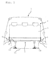
Figur 1 eine schematische Darstellung einer Frontansicht einer in ein Fahrzeug eingebauten Sitzbank, -
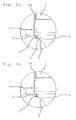
Figur 2a eine vergrößerte Darstellung einer inFigur 1 dargestellten Metallplatte, -
Figur 2b eine alternative Ausgestaltung der inFig. 2a dargestellten Anordnung, -
Figur 3 eine Draufsicht auf einen schematisch dargestellten Sitzbankrahmen. -
Figur 1 zeigt eine in ein Fahrzeug 1 eingebaute Sitzbank 2. Die Sitzbank 2 besitzt eine Rückenlehne 3 und einen gepolsterten Sitzbankrahmen 4. Die Querholme 5 sind seitlich mit Metallplatten 6 verbunden. Die Querholme 5 und die Metallplatten 6 bilden den Sitzbankrahmen 4. Die Querholmendbereiche 7 sind abgeschrägt und die ebenfalls bereichsweise abgeschrägten Metallplatten 6 sind an der Querholmunterseite 8 befestigt, wobei die schrägen Bereiche der Metallplatten 6 mit den abgeschrägten Querholmendbereichen 7 in Anschlag gebracht sind. Auf diese Weise kann der polsterbare Sitzbankrahmen 4 einige Zentimeter über die Radkästen 9 hinausragen. Dadurch wird die Sitzfläche vergrößert und ein komfortables Sitzen auch für drei Personen ermöglicht. Die Sitzbank 2 ist über Kufen 10 mit dem Fahrzeugboden 11 verbunden. Die Kufen 10 sind an nicht dargestellten Längsholmen befestigt, die mit den Querholmen 5 verbunden sind und den Sitzbankrahmen 4 zusätzlich stabilisieren. In diesem Ausführungsbeispiel ist außerdem vorgesehen, dass die Kufen 10 entlang der Querholme 5 verschoben werden können, um die Position der Kufen 10 an die durch den Fahrzeugboden 11 vorgegebenen nicht dargestellten Arretierungsmöglichkeiten anzupassen. - In
Figur 2a ist eine der inFigur 1 gezeigten Metallplatten 6 vergrößert dargestellt. Der waagerechte Teil 12 der Metallplatte 6 ist innerhalb des Querholmendbereichs 7 mit der Querholmunterseite 8 verbunden. Zu diesem Zweck sind in der Metallplatte 6 nicht dargestellte Aufnahmeschlitze vorgesehen, in die der Querholmendbereich 7 eingesetzt wird. Zusätzlich ist der schräge Bereich 13 der Metallplatte 6 an dem abgeschrägten Querholmendbereich 7 befestigt. Der schräge Bereich 13 der Metallplatte 6 ragt über den Radkasten 9. Auf diese Weise wird die Breite des Sitzbankrahmens 4, der aus den Querholmen 5 und den Metallplatten 6 gebildet wird, verlängert. In der Figur sind außerdem die lösbaren Befestigungselemente 14 dargestellt, mit denen die Rückenlehne 3 an der Metallplatte 6 befestigt wird. -
Figur 2b zeigt eine alternative Ausgestaltung der Verbindung der Querholme 5 mit Metallplatten 6. An den Metallplatten 6 sind nicht dargestellte Metallplattenzungen ausgeführt, die in die Querholme 5 eingreifen und dort befestigt werden. Alternativ ist es möglich, seitlich in den Querholmendbereichen 7 Schlitze vorzusehen, in die die Metallplatten 6 eingeschoben werden können. -
Figur 3 zeigt eine Draufsicht auf einen schematisch dargestellten Sitzbankrahmen 4. Die Querholme 5 sind mit dreifach abgekanteten Metallplatten 6 verbunden. Der waagerechte Teil 12 der Metallplatte 6 ist mit der Querholmunterseite 8 verbunden. Zusätzlich ist der schräge Bereich 13 der Metallplatte 6 an dem abgeschrägten Querholmendbereich 7 befestigt. Der Sitzbankrahmen 4 wird zusätzlich durch Längsholme 15 stabilisiert. An diese Längsholme sind die nicht dargestellten Kufen befestigt.
Claims (9)
- Sitzbank (2) für Fahrzeuge, insbesondere für Wohnmobile, mit einer Sitzfläche und einer Rückenlehne (3), wobei die Sitzbank einen Sitzbankrahmen (4) aufweist, an dem die Rückenlehne (3) befestigbar ist und wobei der Sitzbankrahmen (4) mindestens zwei im Wesentlichen parallel angeordnete Querholme (5) aufweist, dadurch gekennzeichnet, dass die Querholme (5) auf mindestens einer Sitzbankseite in einem Querholmendbereich (7) durch eine Metallplatte (6) miteinander verbunden sind.
- Sitzbank nach Anspruch 1, dadurch gekennzeichnet, dass die Metallplatte (6) mindestens einmal in Längsrichtung abgekantet ist.
- Sitzbank nach Anspruch 1 oder Anspruch 2, dadurch gekennzeichnet, dass die Metallplatte (6) zwischen einem waagerecht angeordneten Bereich (12) und einem senkrecht angeordneten Bereich (13) schräg verläuft.
- Sitzbank nach einem der voranstehenden Ansprüche,
dadurch gekennzeichnet, dass der Querholmendbereich (7) abgeschrägt ist. - Sitzbank nach einem der voranstehenden Ansprüche,
dadurch gekennzeichnet, dass die Querholme (5) durch mindestens einen Längsholm (15) in einem Abstand zu dem Querholmendbereich (7) miteinander verbunden sind. - Sitzbank nach einem der voranstehenden Ansprüche,
dadurch gekennzeichnet, dass die Metallplatte eine Dicke zwischen 3mm und 5mm aufweist. - Sitzbank nach einem der voranstehenden Ansprüche,
dadurch gekennzeichnet, dadurch gekennzeichnet, dass die Rückenlehne (3) an der Metallplatte (6) befestigbar ist. - Sitzbank nach einem der voranstehenden Ansprüche,
dadurch gekennzeichnet, dass die Rückenlehne (3) an der Metallplatte (6) drehbar gelagert ist. - Sitzbank nach einem der voranstehenden Ansprüche,
dadurch gekennzeichnet, dass eine Befestigung der Rückenlehne (3) mit der Metallplatte (6) lösbar ist.
Applications Claiming Priority (1)
| Application Number | Priority Date | Filing Date | Title |
|---|---|---|---|
| DE201020008374 DE202010008374U1 (de) | 2010-08-26 | 2010-08-26 | Sitzbank für Fahrzeuge |
Publications (2)
| Publication Number | Publication Date |
|---|---|
| EP2423045A1 true EP2423045A1 (de) | 2012-02-29 |
| EP2423045B1 EP2423045B1 (de) | 2016-10-05 |
Family
ID=43028940
Family Applications (1)
| Application Number | Title | Priority Date | Filing Date |
|---|---|---|---|
| EP11178732.1A Active EP2423045B1 (de) | 2010-08-26 | 2011-08-24 | Sitzbank für Fahrzeuge |
Country Status (2)
| Country | Link |
|---|---|
| EP (1) | EP2423045B1 (de) |
| DE (1) | DE202010008374U1 (de) |
Citations (2)
| Publication number | Priority date | Publication date | Assignee | Title |
|---|---|---|---|---|
| WO2006075413A1 (ja) * | 2005-01-13 | 2006-07-20 | Recaro Japan Co., Ltd. | 自動車用シートのシートクッションフレーム |
| US20090184562A1 (en) * | 2008-01-18 | 2009-07-23 | International Truck Intellectual Property Company, Llc | School bus seat frame back attachment |
-
2010
- 2010-08-26 DE DE201020008374 patent/DE202010008374U1/de not_active Expired - Lifetime
-
2011
- 2011-08-24 EP EP11178732.1A patent/EP2423045B1/de active Active
Patent Citations (2)
| Publication number | Priority date | Publication date | Assignee | Title |
|---|---|---|---|---|
| WO2006075413A1 (ja) * | 2005-01-13 | 2006-07-20 | Recaro Japan Co., Ltd. | 自動車用シートのシートクッションフレーム |
| US20090184562A1 (en) * | 2008-01-18 | 2009-07-23 | International Truck Intellectual Property Company, Llc | School bus seat frame back attachment |
Also Published As
| Publication number | Publication date |
|---|---|
| EP2423045B1 (de) | 2016-10-05 |
| DE202010008374U1 (de) | 2010-10-28 |
Similar Documents
| Publication | Publication Date | Title |
|---|---|---|
| DE102005042403B3 (de) | Modulares Sitzsystem für ein Fahrzeug | |
| EP2583862B1 (de) | Fahrzeugsitz, insbesondere Schienenfahrzeugsitz, mit einem Polsterelementbefestigungsrahmen | |
| DE102008038851A1 (de) | Lehnenrahmen eines Fahrzeugsitzes | |
| DE102016109789B4 (de) | Sitzsystem für eine Kabine eines Transportmittels mit kompaktierbarer Sitzreihe | |
| DE102013009761B4 (de) | Bodenstruktur des mittleren Bereichs einer Fahrzeugkarosserie | |
| DE2113579A1 (de) | Vorrichtung zum Befestigen von Sicherheitseinrichtungen in einem Fahrzeug | |
| DE102015216171A1 (de) | Sitzbefestigungssystem für ein Fahrzeug | |
| DE102012012250B4 (de) | Fahrzeugsitz | |
| EP3539818B1 (de) | Gurtgestell für einen fahrzeugsitz oder eine fahrzeugsitzbank und fahrzeug-sitzanordnung | |
| DE102016108858A1 (de) | Vorrichtung zur Anbringung einer Sitzanordnung an einem Fahrzeug und Fahrzeug | |
| DE102010039409B4 (de) | Fahrzeugsitz mit ausgewölbter Rückenlehne | |
| EP2423045B1 (de) | Sitzbank für Fahrzeuge | |
| DE1198680B (de) | Einrichtung zur Umwandlung eines Frachtflugzeuges in ein Passagierflugzeug | |
| EP3231665A1 (de) | Vorrichtung zur anbringung eines sicherheitsgurtsystems | |
| DE9302831U1 (de) | Kombinationskraftfahrzeug | |
| DE202011051081U1 (de) | Liegeeinrichtung für ein Kraftfahrzeug | |
| DE102012013114B4 (de) | Kopfstützen-tragestruktur | |
| DE102004032292B4 (de) | Fahrzeugeinrichtung mit einem klapptischähnlichen Einsatz zur Liegeflächenvergrößerung | |
| DE19927532C2 (de) | Mechanismus zum Anbringen eines Sicherheitsgurtes eines mittleren Sitzplatzes von einem Fahrzeugsitz | |
| EP3785984B1 (de) | Sitzgestell für eine fahrzeugsitzanordnung | |
| EP3536548B1 (de) | Flurförderzeug mit einer fahrerkabine | |
| DE102014211528A1 (de) | Verkehrsmittelsitz | |
| EP2774513B1 (de) | Bett | |
| DE3522825C2 (de) | ||
| DE102005008896B4 (de) | Sitzeinheit |
Legal Events
| Date | Code | Title | Description |
|---|---|---|---|
| AK | Designated contracting states |
Kind code of ref document: A1 Designated state(s): AL AT BE BG CH CY CZ DE DK EE ES FI FR GB GR HR HU IE IS IT LI LT LU LV MC MK MT NL NO PL PT RO RS SE SI SK SM TR |
|
| AX | Request for extension of the european patent |
Extension state: BA ME |
|
| PUAI | Public reference made under article 153(3) epc to a published international application that has entered the european phase |
Free format text: ORIGINAL CODE: 0009012 |
|
| 17P | Request for examination filed |
Effective date: 20120829 |
|
| 17Q | First examination report despatched |
Effective date: 20140224 |
|
| GRAP | Despatch of communication of intention to grant a patent |
Free format text: ORIGINAL CODE: EPIDOSNIGR1 |
|
| INTG | Intention to grant announced |
Effective date: 20151030 |
|
| GRAP | Despatch of communication of intention to grant a patent |
Free format text: ORIGINAL CODE: EPIDOSNIGR1 |
|
| INTG | Intention to grant announced |
Effective date: 20160504 |
|
| GRAS | Grant fee paid |
Free format text: ORIGINAL CODE: EPIDOSNIGR3 |
|
| GRAA | (expected) grant |
Free format text: ORIGINAL CODE: 0009210 |
|
| AK | Designated contracting states |
Kind code of ref document: B1 Designated state(s): AL AT BE BG CH CY CZ DE DK EE ES FI FR GB GR HR HU IE IS IT LI LT LU LV MC MK MT NL NO PL PT RO RS SE SI SK SM TR |
|
| REG | Reference to a national code |
Ref country code: GB Ref legal event code: FG4D Free format text: NOT ENGLISH |
|
| REG | Reference to a national code |
Ref country code: CH Ref legal event code: EP |
|
| REG | Reference to a national code |
Ref country code: AT Ref legal event code: REF Ref document number: 834310 Country of ref document: AT Kind code of ref document: T Effective date: 20161015 |
|
| REG | Reference to a national code |
Ref country code: IE Ref legal event code: FG4D Free format text: LANGUAGE OF EP DOCUMENT: GERMAN |
|
| REG | Reference to a national code |
Ref country code: DE Ref legal event code: R096 Ref document number: 502011010822 Country of ref document: DE |
|
| REG | Reference to a national code |
Ref country code: NL Ref legal event code: MP Effective date: 20161005 |
|
| REG | Reference to a national code |
Ref country code: LT Ref legal event code: MG4D |
|
| PG25 | Lapsed in a contracting state [announced via postgrant information from national office to epo] |
Ref country code: LV Free format text: LAPSE BECAUSE OF FAILURE TO SUBMIT A TRANSLATION OF THE DESCRIPTION OR TO PAY THE FEE WITHIN THE PRESCRIBED TIME-LIMIT Effective date: 20161005 |
|
| PG25 | Lapsed in a contracting state [announced via postgrant information from national office to epo] |
Ref country code: GR Free format text: LAPSE BECAUSE OF FAILURE TO SUBMIT A TRANSLATION OF THE DESCRIPTION OR TO PAY THE FEE WITHIN THE PRESCRIBED TIME-LIMIT Effective date: 20170106 Ref country code: NO Free format text: LAPSE BECAUSE OF FAILURE TO SUBMIT A TRANSLATION OF THE DESCRIPTION OR TO PAY THE FEE WITHIN THE PRESCRIBED TIME-LIMIT Effective date: 20170105 Ref country code: LT Free format text: LAPSE BECAUSE OF FAILURE TO SUBMIT A TRANSLATION OF THE DESCRIPTION OR TO PAY THE FEE WITHIN THE PRESCRIBED TIME-LIMIT Effective date: 20161005 Ref country code: SE Free format text: LAPSE BECAUSE OF FAILURE TO SUBMIT A TRANSLATION OF THE DESCRIPTION OR TO PAY THE FEE WITHIN THE PRESCRIBED TIME-LIMIT Effective date: 20161005 |
|
| PG25 | Lapsed in a contracting state [announced via postgrant information from national office to epo] |
Ref country code: PT Free format text: LAPSE BECAUSE OF FAILURE TO SUBMIT A TRANSLATION OF THE DESCRIPTION OR TO PAY THE FEE WITHIN THE PRESCRIBED TIME-LIMIT Effective date: 20170206 Ref country code: IS Free format text: LAPSE BECAUSE OF FAILURE TO SUBMIT A TRANSLATION OF THE DESCRIPTION OR TO PAY THE FEE WITHIN THE PRESCRIBED TIME-LIMIT Effective date: 20170205 Ref country code: ES Free format text: LAPSE BECAUSE OF FAILURE TO SUBMIT A TRANSLATION OF THE DESCRIPTION OR TO PAY THE FEE WITHIN THE PRESCRIBED TIME-LIMIT Effective date: 20161005 Ref country code: PL Free format text: LAPSE BECAUSE OF FAILURE TO SUBMIT A TRANSLATION OF THE DESCRIPTION OR TO PAY THE FEE WITHIN THE PRESCRIBED TIME-LIMIT Effective date: 20161005 Ref country code: NL Free format text: LAPSE BECAUSE OF FAILURE TO SUBMIT A TRANSLATION OF THE DESCRIPTION OR TO PAY THE FEE WITHIN THE PRESCRIBED TIME-LIMIT Effective date: 20161005 Ref country code: RS Free format text: LAPSE BECAUSE OF FAILURE TO SUBMIT A TRANSLATION OF THE DESCRIPTION OR TO PAY THE FEE WITHIN THE PRESCRIBED TIME-LIMIT Effective date: 20161005 Ref country code: FI Free format text: LAPSE BECAUSE OF FAILURE TO SUBMIT A TRANSLATION OF THE DESCRIPTION OR TO PAY THE FEE WITHIN THE PRESCRIBED TIME-LIMIT Effective date: 20161005 Ref country code: HR Free format text: LAPSE BECAUSE OF FAILURE TO SUBMIT A TRANSLATION OF THE DESCRIPTION OR TO PAY THE FEE WITHIN THE PRESCRIBED TIME-LIMIT Effective date: 20161005 |
|
| REG | Reference to a national code |
Ref country code: DE Ref legal event code: R097 Ref document number: 502011010822 Country of ref document: DE |
|
| PG25 | Lapsed in a contracting state [announced via postgrant information from national office to epo] |
Ref country code: DK Free format text: LAPSE BECAUSE OF FAILURE TO SUBMIT A TRANSLATION OF THE DESCRIPTION OR TO PAY THE FEE WITHIN THE PRESCRIBED TIME-LIMIT Effective date: 20161005 Ref country code: SK Free format text: LAPSE BECAUSE OF FAILURE TO SUBMIT A TRANSLATION OF THE DESCRIPTION OR TO PAY THE FEE WITHIN THE PRESCRIBED TIME-LIMIT Effective date: 20161005 Ref country code: EE Free format text: LAPSE BECAUSE OF FAILURE TO SUBMIT A TRANSLATION OF THE DESCRIPTION OR TO PAY THE FEE WITHIN THE PRESCRIBED TIME-LIMIT Effective date: 20161005 Ref country code: CZ Free format text: LAPSE BECAUSE OF FAILURE TO SUBMIT A TRANSLATION OF THE DESCRIPTION OR TO PAY THE FEE WITHIN THE PRESCRIBED TIME-LIMIT Effective date: 20161005 Ref country code: RO Free format text: LAPSE BECAUSE OF FAILURE TO SUBMIT A TRANSLATION OF THE DESCRIPTION OR TO PAY THE FEE WITHIN THE PRESCRIBED TIME-LIMIT Effective date: 20161005 |
|
| PLBE | No opposition filed within time limit |
Free format text: ORIGINAL CODE: 0009261 |
|
| STAA | Information on the status of an ep patent application or granted ep patent |
Free format text: STATUS: NO OPPOSITION FILED WITHIN TIME LIMIT |
|
| REG | Reference to a national code |
Ref country code: FR Ref legal event code: PLFP Year of fee payment: 7 |
|
| PG25 | Lapsed in a contracting state [announced via postgrant information from national office to epo] |
Ref country code: SM Free format text: LAPSE BECAUSE OF FAILURE TO SUBMIT A TRANSLATION OF THE DESCRIPTION OR TO PAY THE FEE WITHIN THE PRESCRIBED TIME-LIMIT Effective date: 20161005 Ref country code: BG Free format text: LAPSE BECAUSE OF FAILURE TO SUBMIT A TRANSLATION OF THE DESCRIPTION OR TO PAY THE FEE WITHIN THE PRESCRIBED TIME-LIMIT Effective date: 20170105 |
|
| 26N | No opposition filed |
Effective date: 20170706 |
|
| PG25 | Lapsed in a contracting state [announced via postgrant information from national office to epo] |
Ref country code: SI Free format text: LAPSE BECAUSE OF FAILURE TO SUBMIT A TRANSLATION OF THE DESCRIPTION OR TO PAY THE FEE WITHIN THE PRESCRIBED TIME-LIMIT Effective date: 20161005 |
|
| REG | Reference to a national code |
Ref country code: CH Ref legal event code: PL |
|
| PG25 | Lapsed in a contracting state [announced via postgrant information from national office to epo] |
Ref country code: MC Free format text: LAPSE BECAUSE OF FAILURE TO SUBMIT A TRANSLATION OF THE DESCRIPTION OR TO PAY THE FEE WITHIN THE PRESCRIBED TIME-LIMIT Effective date: 20161005 |
|
| PG25 | Lapsed in a contracting state [announced via postgrant information from national office to epo] |
Ref country code: LI Free format text: LAPSE BECAUSE OF NON-PAYMENT OF DUE FEES Effective date: 20170831 Ref country code: CH Free format text: LAPSE BECAUSE OF NON-PAYMENT OF DUE FEES Effective date: 20170831 |
|
| REG | Reference to a national code |
Ref country code: IE Ref legal event code: MM4A |
|
| REG | Reference to a national code |
Ref country code: BE Ref legal event code: MM Effective date: 20170831 |
|
| PG25 | Lapsed in a contracting state [announced via postgrant information from national office to epo] |
Ref country code: LU Free format text: LAPSE BECAUSE OF NON-PAYMENT OF DUE FEES Effective date: 20170824 |
|
| PG25 | Lapsed in a contracting state [announced via postgrant information from national office to epo] |
Ref country code: IE Free format text: LAPSE BECAUSE OF NON-PAYMENT OF DUE FEES Effective date: 20170824 |
|
| REG | Reference to a national code |
Ref country code: FR Ref legal event code: PLFP Year of fee payment: 8 |
|
| PG25 | Lapsed in a contracting state [announced via postgrant information from national office to epo] |
Ref country code: BE Free format text: LAPSE BECAUSE OF NON-PAYMENT OF DUE FEES Effective date: 20170831 |
|
| PG25 | Lapsed in a contracting state [announced via postgrant information from national office to epo] |
Ref country code: MT Free format text: LAPSE BECAUSE OF FAILURE TO SUBMIT A TRANSLATION OF THE DESCRIPTION OR TO PAY THE FEE WITHIN THE PRESCRIBED TIME-LIMIT Effective date: 20161005 |
|
| REG | Reference to a national code |
Ref country code: AT Ref legal event code: MM01 Ref document number: 834310 Country of ref document: AT Kind code of ref document: T Effective date: 20170824 |
|
| PG25 | Lapsed in a contracting state [announced via postgrant information from national office to epo] |
Ref country code: AT Free format text: LAPSE BECAUSE OF NON-PAYMENT OF DUE FEES Effective date: 20170824 |
|
| PG25 | Lapsed in a contracting state [announced via postgrant information from national office to epo] |
Ref country code: HU Free format text: LAPSE BECAUSE OF FAILURE TO SUBMIT A TRANSLATION OF THE DESCRIPTION OR TO PAY THE FEE WITHIN THE PRESCRIBED TIME-LIMIT; INVALID AB INITIO Effective date: 20110824 |
|
| PG25 | Lapsed in a contracting state [announced via postgrant information from national office to epo] |
Ref country code: CY Free format text: LAPSE BECAUSE OF NON-PAYMENT OF DUE FEES Effective date: 20161005 |
|
| PG25 | Lapsed in a contracting state [announced via postgrant information from national office to epo] |
Ref country code: MK Free format text: LAPSE BECAUSE OF FAILURE TO SUBMIT A TRANSLATION OF THE DESCRIPTION OR TO PAY THE FEE WITHIN THE PRESCRIBED TIME-LIMIT Effective date: 20161005 |
|
| PG25 | Lapsed in a contracting state [announced via postgrant information from national office to epo] |
Ref country code: TR Free format text: LAPSE BECAUSE OF FAILURE TO SUBMIT A TRANSLATION OF THE DESCRIPTION OR TO PAY THE FEE WITHIN THE PRESCRIBED TIME-LIMIT Effective date: 20161005 |
|
| PG25 | Lapsed in a contracting state [announced via postgrant information from national office to epo] |
Ref country code: AL Free format text: LAPSE BECAUSE OF FAILURE TO SUBMIT A TRANSLATION OF THE DESCRIPTION OR TO PAY THE FEE WITHIN THE PRESCRIBED TIME-LIMIT Effective date: 20161005 |
|
| PGFP | Annual fee paid to national office [announced via postgrant information from national office to epo] |
Ref country code: DE Payment date: 20250703 Year of fee payment: 15 |
|
| PGFP | Annual fee paid to national office [announced via postgrant information from national office to epo] |
Ref country code: IT Payment date: 20250829 Year of fee payment: 15 |
|
| PGFP | Annual fee paid to national office [announced via postgrant information from national office to epo] |
Ref country code: GB Payment date: 20250822 Year of fee payment: 15 |
|
| PGFP | Annual fee paid to national office [announced via postgrant information from national office to epo] |
Ref country code: FR Payment date: 20250821 Year of fee payment: 15 |