EP2421580B1 - Aufnahmeeinrichtung zum aufnehmen von medizinischen fluiden sowie externe funktionseinrichtung und medizinische behandlungsvorrichtung - Google Patents
Aufnahmeeinrichtung zum aufnehmen von medizinischen fluiden sowie externe funktionseinrichtung und medizinische behandlungsvorrichtung Download PDFInfo
- Publication number
- EP2421580B1 EP2421580B1 EP10713854.7A EP10713854A EP2421580B1 EP 2421580 B1 EP2421580 B1 EP 2421580B1 EP 10713854 A EP10713854 A EP 10713854A EP 2421580 B1 EP2421580 B1 EP 2421580B1
- Authority
- EP
- European Patent Office
- Prior art keywords
- receiving device
- fluid
- flow
- surge
- inflow
- Prior art date
- Legal status (The legal status is an assumption and is not a legal conclusion. Google has not performed a legal analysis and makes no representation as to the accuracy of the status listed.)
- Active
Links
Images


Classifications
-
- A—HUMAN NECESSITIES
- A61—MEDICAL OR VETERINARY SCIENCE; HYGIENE
- A61M—DEVICES FOR INTRODUCING MEDIA INTO, OR ONTO, THE BODY; DEVICES FOR TRANSDUCING BODY MEDIA OR FOR TAKING MEDIA FROM THE BODY; DEVICES FOR PRODUCING OR ENDING SLEEP OR STUPOR
- A61M1/00—Suction or pumping devices for medical purposes; Devices for carrying-off, for treatment of, or for carrying-over, body-liquids; Drainage systems
- A61M1/36—Other treatment of blood in a by-pass of the natural circulatory system, e.g. temperature adaptation, irradiation ; Extra-corporeal blood circuits
- A61M1/3621—Extra-corporeal blood circuits
- A61M1/3627—Degassing devices; Buffer reservoirs; Drip chambers; Blood filters
-
- A—HUMAN NECESSITIES
- A61—MEDICAL OR VETERINARY SCIENCE; HYGIENE
- A61M—DEVICES FOR INTRODUCING MEDIA INTO, OR ONTO, THE BODY; DEVICES FOR TRANSDUCING BODY MEDIA OR FOR TAKING MEDIA FROM THE BODY; DEVICES FOR PRODUCING OR ENDING SLEEP OR STUPOR
- A61M1/00—Suction or pumping devices for medical purposes; Devices for carrying-off, for treatment of, or for carrying-over, body-liquids; Drainage systems
- A61M1/36—Other treatment of blood in a by-pass of the natural circulatory system, e.g. temperature adaptation, irradiation ; Extra-corporeal blood circuits
- A61M1/3621—Extra-corporeal blood circuits
- A61M1/3622—Extra-corporeal blood circuits with a cassette forming partially or totally the blood circuit
- A61M1/36226—Constructional details of cassettes, e.g. specific details on material or shape
- A61M1/362265—Details of valves
-
- A—HUMAN NECESSITIES
- A61—MEDICAL OR VETERINARY SCIENCE; HYGIENE
- A61M—DEVICES FOR INTRODUCING MEDIA INTO, OR ONTO, THE BODY; DEVICES FOR TRANSDUCING BODY MEDIA OR FOR TAKING MEDIA FROM THE BODY; DEVICES FOR PRODUCING OR ENDING SLEEP OR STUPOR
- A61M1/00—Suction or pumping devices for medical purposes; Devices for carrying-off, for treatment of, or for carrying-over, body-liquids; Drainage systems
- A61M1/36—Other treatment of blood in a by-pass of the natural circulatory system, e.g. temperature adaptation, irradiation ; Extra-corporeal blood circuits
- A61M1/3621—Extra-corporeal blood circuits
- A61M1/3622—Extra-corporeal blood circuits with a cassette forming partially or totally the blood circuit
- A61M1/36226—Constructional details of cassettes, e.g. specific details on material or shape
- A61M1/362262—Details of incorporated reservoirs
-
- A—HUMAN NECESSITIES
- A61—MEDICAL OR VETERINARY SCIENCE; HYGIENE
- A61M—DEVICES FOR INTRODUCING MEDIA INTO, OR ONTO, THE BODY; DEVICES FOR TRANSDUCING BODY MEDIA OR FOR TAKING MEDIA FROM THE BODY; DEVICES FOR PRODUCING OR ENDING SLEEP OR STUPOR
- A61M2205/00—General characteristics of the apparatus
- A61M2205/12—General characteristics of the apparatus with interchangeable cassettes forming partially or totally the fluid circuit
-
- A—HUMAN NECESSITIES
- A61—MEDICAL OR VETERINARY SCIENCE; HYGIENE
- A61M—DEVICES FOR INTRODUCING MEDIA INTO, OR ONTO, THE BODY; DEVICES FOR TRANSDUCING BODY MEDIA OR FOR TAKING MEDIA FROM THE BODY; DEVICES FOR PRODUCING OR ENDING SLEEP OR STUPOR
- A61M2206/00—Characteristics of a physical parameter; associated device therefor
- A61M2206/10—Flow characteristics
Definitions
- the present invention relates to a receiving device for receiving medical fluids according to the preamble of claim 1. It further relates to an external functional device according to claim 14 and a medical treatment device according to claim 15.
- Various devices such as medical device treatment devices, have receiving means for temporarily receiving fluids. These are repeatedly filled with fluid during operation of the device iaR and also emptied again. Flow phenomena that usually occur during filling and emptying are regularly influenced by suitable structural measures. These include container wall nozzles, baffles and geometric configurations of components, for example in dip tube shapes, diffuser shapes and the like.
- the US 7,279,031 B1 discloses a device for preventing thrombosis.
- the US 2009/0084721 A1 discloses dialysis systems with air separators.
- the WO 2007/000066 A1 discloses a method and apparatus for draining and removing certain material.
- the US 6,013,060 A discloses a device for regulating intravenously applied fluids.
- the US 2005/230292 A1 discloses a device for the treatment of medical fluids, comprising a cartridge with phantom valves.
- An object of the present invention is to provide a further receiving device for receiving medical fluids, in particular blood, with a device for influencing a fluid flow.
- the object according to the invention is achieved by a receiving device for receiving one or more medical fluids having the features of claim 1.
- the receiving device has an inflow opening, through which at least one medical fluid into an interior of the receiving device is insertable or einbringbar. It also has at least one fluid flow bypass element for diverting the fluid surge of the inflowing fluid.
- inflow port refers to an opening or recess - e.g. B. in a side or side surface or side wall of the receiving device - through which a fluid flow into the closed or open to the environment interior of the receiving device, can enter or flow.
- a "fluid” includes any medical fluid and / or medical gas and / or liquid-gas mixture (e.g., gas bubbles in fluid, foam, especially blood with air bubbles, blood foam). In particular, it may be blood in an extracorporeal blood circulation.
- fluid is to be understood here and in the following synonymous as a medical fluid.
- An “interior of the receiving device” denotes a volume or a volume of the receiving device which is suitable and intended for full or partial filling with fluids and receiving them.
- a “fluid flow diverting element” refers to a body which is suitable for influencing a fluid surge, in particular for diverting a fluid surge impinging on it. This body may be an umströmungsund and / or overflow element.
- the fluid flow bypass element according to the invention can also be understood as a fluid contact element which is provided in the receiving device with the aim of flowing into the interior of the receiving device Fluid surge to be met or to get in touch with this.
- This contact is deliberately designed to affect the surge of fluid in an intended manner. This may mean weakening the pulse of the fluid surge, canceling out the pulse of fluid surge in the sense of transmission. In particular, it can also mean a deliberate division of the fluid surge into at least two traceable fluid component surge or many small fluid partial surge, as will be explained in more detail below.
- the fluid surge bypass element has at least one bypass body which is designed and / or provided and is suitable for dividing the fluid surge into at least two partial flows.
- the sub-streams are after their division - at least temporarily - physically separated from each other, ie without contact with each other before.
- fluid surge refers to a quantity or volume of the fluid introduced or entering the receiving device.
- the fluid surge may be a continuous and / or constant (e.g., inflowing at a constant rate) fluid surge, or a fluid surge flowing into the receiver at a particular time and / or only for a limited, predetermined period of time.
- the fluid surge can transmit a pulse.
- the fluid surge may be such that its inflow into the receiving device without providing a fluid surge diverter as described above results in turbulence and / or gas inclusions (especially of air) in the incoming fluid (particularly a liquid) or in a fluid into which another fluid should flow (especially blood) would lead.
- partial fluid surge refers to a partial flow obtained by dividing the fluid surge initially flowing into the receiving device by means of the bypass body or a partial volume of the total fluid surge originally flowed in.
- the partial fluid surge is a component of the fluid surge.
- the entirety of all portions of the partial fluid bumps obtained by means of the bypass body, which remain in the interior of the receiving device after splitting the fluid surge into the partial fluid surge, may add up to substantially 100% of the total fluid surge in a preferred embodiment of the invention. This means that all Crystalfluidschwalle continue to enter the receiving device or initially remain in this.
- the proportions of the flow volume or the flow rate of the individual Partfluidschwalls may each be the same or different from each other.
- the bypass body is disposed in an inflow area of the fluid surge, and in the outflow area of a phantom valve in a blood cassette for extracorporeal blood treatment.
- phantom valve refers to an element with an actuator surface achievable by means of an actuator (here, for example, an actuator membrane), which can assume the function of a valve.
- the actuator membrane is applied thereto by applying a force thereto, e.g. a compressive force, movable in one direction, expandable, or the like. By moving or expanding the actuator membrane, it can attach to or remove from an element, such as a sealing device, such as a web.
- a force thereto e.g. a compressive force, movable in one direction, expandable, or the like.
- By moving or expanding the actuator membrane it can attach to or remove from an element, such as a sealing device, such as a web.
- the actuator membrane can thus effect, for example, a seal or strengthen or terminate or reduce.
- a home position e.g. a non-curved state
- inflow region designates the region of the receiving device in which the fluid surge is located immediately after flowing into or flowing into the receiving device.
- the inflow region can form a receptacle-side region around the inflow opening in spatial relation to it, in which the fluid flowing in through the inflow opening begins to spread in the receptacle and the receptacle begins to fill.
- bypass body is arranged centrally (or in a central region) in the inflow region of the fluid, with respect to a central axis of the inflow opening or the inflow direction.
- the "center axis" designates, for example, that axis which is perpendicular to a central region or a center point of the cross section of the inflow opening or the inflow direction, such as, for example, the circular center of an inflow opening with a circular cross section.
- the central axis can run parallel to a main flow device of the entire fluid surge prior to its division into Generalfluidschwalle.
- central and centered are used in the present invention to be synonymous or interchangeable. They are each intended to denote an arrangement of a component in a middle region or the center of a reference system or a reference component.
- a central or central arrangement is preferably defined such that the center of shape, e.g. the circle center point of the cross section of a component, is arranged on a central axis or a center of the reference component.
- the center of the form, the central axis or the center can, as is generally customary, be geometrically determined or approximately determined.
- cross-section may be understood to mean a cross section perpendicular to or parallel to an inflow direction.
- the "cross section” in the discussion of the present invention, regardless of further features thereof, may preferably be the cross section of maximum diameter or dimensions.
- the inflow opening may be arranged, for example, in a surface interior or a middle of a side or side surface or side wall of the receiving device. However, it can also be arranged in an edge region of the side or a boundary of the receiving device.
- the inflow opening may extend over a substantially entire length of one side of the receiving device. Irrespective of this, the inflow opening may extend over a substantially entire width of the side of the receiving device. It can therefore assume different spatial configurations.
- the inflow opening is provided substantially centered in a boundary surface of the receiving device, ie, the center (for example, the circular center of an inflow opening with a circular Cross-section) of the inflow opening may be arranged at half the length and / or half the width of the side surface of the receiving device.
- the inflow port may have a circular or elliptical cross-section, but it may also have any other cross-section which seems suitable for the purpose of the present invention.
- in the receiving device can also be provided in the receiving device a plurality of identically or differently configured inflow openings.
- the configuration of the same can each be optimized for flow and suitably selected for the intended purpose.
- At least one of the inflow openings can have a fluid flow diverting element or a circulating body in the inflow region of the fluid swell.
- the bypass body may preferably be designed symmetrically.
- the bypass body may preferably be configured or arranged symmetrically with respect to the central axis of the inflow opening.
- a cross-section of the bypass body can be symmetrically arranged or provided in a plane perpendicular to the inflow direction of the fluid surge introduced into the receiving device relative to the central axis of the inflow opening.
- a symmetry is provided in the vicinity of the fluid flow element.
- the entire device does not necessarily have to be symmetrical.
- the bypass body may generally include a front or baffle on which the incoming fluid surge or a substantial portion thereof impinges, and a Rear side, at which the Generalfluidschwalle can be brought together have.
- Rejoining the divided partial fluid surge at a rear portion of the bypass body or a downstream portion thereof is contemplated by the invention.
- the invention is not limited to a re-merging; In other words, this is not a required effect of each embodiment of the invention.
- the bypass body may further comprise left and right side flanks, along which a partial fluid surge can flow.
- a symmetrically configured flow-around body can be designed such that the geometric shape or configuration of the left and the right side flank is provided mirror-symmetrically to the central axis of the inflow opening.
- the geometric shape of the front and back of the bypass body may also be mirror-symmetrical to an axis perpendicular to the center axis of the inflow port, i. be arranged perpendicular to the flow direction of the flowing into the receiving device fluid surge.
- the invention is not limited thereto.
- the cross section of the Umströmungs emotionss be circular, in which case the Umströmungs redesign itself is configured rotationally symmetrical.
- the cross section of the bypass body may be configured elliptical, in which case in each case the left and right side flanks of the bypass body and the front and the back of the bypass body are symmetrical to one another.
- the cross section of the Umströmungs stressess may also be paraboloid or gothic pointed or designed differently.
- the cross-section of the bypass body may vary along the height or depth of the bypass body.
- the cross-sectional area may vary over the height of the bypass body, e.g.
- the cross sectional area or a diameter thereof may be tapered over the height, i. get smaller or lose weight.
- the cross-section of the bypass body may also remain constant along the height or depth of the bypass body.
- the cross-sectional area or the diameter can decrease and increase several times over the height of the flow body and (or vice versa) in order to achieve a fluid flow diversion optimized for the respective application and the respectively used fluid.
- the bypass body may be configured to divide the fluid surge initially introduced into the receiver into more than two partial fluid jets.
- the flow-around body can, for example, have a passage opening for the passage of a third partial fluid surge in a central area.
- the passage opening may extend, for example, from the front to the rear of the bypass body.
- the Umströmungsharm with the 0.4 times to 2 times the diameter of the inflow opening or the flow channel diameter of the inflow opening spaced in the inflow region of the receiving device is arranged.
- This distance may preferably refer to a distance between the inflow port, for example the mouth of the inflow port in the side face or side wall of the take-up device, and the front (e.g., the farthest upstream of the fluid surge or the one main impact point of fluid surge) point of the bypass body.
- a diameter of the bypass body in a plane perpendicular to the central axis or perpendicular to the main impingement direction of the fluid surge on the inflow body of the inflow port may be 0.4 to 1.2 times the diameter of the inflow port or the flow channel diameter.
- This diameter may preferably be the maximum diameter of the bypass body, for example, the longer diameter of a Umströmungs stressess with elliptical cross-section, as in Fig. 1 is shown.
- Fluidschwallum grista
- the fluid bypass diversion element or the bypass body may be designed or shaped together with it. This can be achieved for example by means of injection molding of the receiving device.
- the receiving device may be configured, for example, as a prismatic injection molding chamber.
- the receiving device may be configured in cassette form or as part of such. It may be, for example, an external functional device or part of an external functional device.
- the receiving device may preferably be integrally integrated into the external functional device.
- the receiving device is connected to the inflow opening with an inflow channel. It may alternatively be connected to a plurality of inflow channels.
- the connection channel or inflow channel can be integrally integrated in the lower end of the receiving device.
- the inflow channel may be a closed, semi-open channel or conduit. It can be integrated in an external functional device. Such a channel or such a line can be designed or formed during the production of the external functional device, for example by means of injection molding.
- the inflow opening may be suitable and provided to allow fluids flowed into the interior of the receiving device to flow out.
- This may be advantageous, for example, to accomplish the most complete exchange of fluids when filling or emptying the receiving device.
- the receiving device is part of an external functional device, such as a blood cassette or blood treatment cassette, and a space-saving arrangement of the individual components of the blood cassette is essential or required or desired.
- the inflow or outflow opening can be provided, for example, with one or more different and / or different or differently configured or provided projections, indentations, Flow or Umströmungs instituten and the like in the opening itself, ie in the passage area thereof, be provided.
- the drainage channel or the outflow channel can be arranged at the geodetically lowest point of the receiving device.
- the side walls of the receiving device may have a certain minimum slope in the vicinity of the drainage channel or the outflow channel, which may facilitate the outflow of the fluids present in the receiving device.
- a not completely vertically aligned receiving device idle.
- flow stagnation zones can advantageously be reduced or even avoided with such an arrangement.
- the receiving device is arranged in an extracorporeal blood circulation.
- the fluid surge redirecting element in particular a blood surge redirection element or blood surge element, may be suitable and provided for achieving a flow deceleration, for generating turbulence and / or diverting a blood pressure present in a single-needle chamber or for canceling out the pulse of the blood surge.
- Such Blutschwallum Oberselement can be designed in particular flow optimized. It may be configured, for example, in the form of an ellipsoidal or round column, which is connected at at least a portion of its circumference to a wall of the single-needle chamber.
- the object according to the invention is also achieved by an external functional device according to claim 14. All achievable by means of the receiving device according to the invention advantages can also be achieved with the external functional device according to the invention.
- An external functional device has at least one receiving device according to the invention.
- the external functional device according to the invention can be provided for use in a treatment method, in particular in an extracorporeal blood treatment method.
- Treatment methods in the sense of the present invention include medical treatment methods - in particular blood treatment methods such as dialysis methods, methods of laboratory technology, methods of food or drug production and the like.
- the external functional device according to the invention is designed as a blood cassette.
- the external functional device may be provided for use in or on a treatment device.
- the external functional device may be provided on at least one side with a cover element.
- a "cover member” may be a membrane, a foil, and the like.
- Exemplary embodiments for suitable cover elements as well as their design and arrangement on the external functional device can be, for example, the application filed by the applicant of the present invention at the DPMA on 10 March 2009 10 2009 012 632 A1 with the title "Sealing device for sealing a volume of a medical treatment device against another volume as well as arrangement and method” .
- the cover element of the external functional device can preferably be arranged or provided such that it rests on an upper side of the bypass body, in particular on a sealing web circulating on the upper side of the bypass body.
- the seal between the sealing device and the upper surface of the Umströmungs stressess provide a seal for the fluid contained in the interior of the receptacle, so that it is not from the receiving device out of the receptacle into other compartments of the external functional device and or in an exterior of the external Functional device can get.
- the external functional device may, for example, be designed as a blood cassette, as described in the applications filed by the applicant of the present invention in the applications filed with the DPMA on April 23, 2009 and June 10, 2009, respectively 10 2009 018 664 A1 respectively. 10 2009 024 468 A1 each with the title "External functional device, blood treatment device for receiving an external functional device according to the invention, and method" is described.
- Such an external functional device may be a disposable component or a disposable article.
- the external functional device may for example be made of a plastic material.
- the external functional device can be used as an injection-molded hard part with a welded cover device, e.g. a film, be configured.
- the object of the invention is also achieved by a medical treatment device according to the invention according to claim 15. All advantages that can be achieved with the receiving device according to the invention, can be achieved with the treatment device according to the invention.
- the treatment device according to the invention may comprise at least one receiving device according to the invention and / or at least one external functional device according to the invention.
- the treatment device can be used in a treatment method as stated above.
- the treatment device may be a blood treatment device such as a dialyzer for performing a dialysis treatment such as hemodialysis, hemofiltration, hemodiafiltration and the like.
- the present invention may advantageously be suitable and provided for soothing a fluid flow or fluid surge flowing into a receiving device.
- the receiving device has a significantly larger cross-section than the hose, pipe, channel or valve cross sections, via which fluids are introduced into the receiving device.
- the present invention it is possible to control the turbulence and / or irregularities that usually occur in the course of cross-sectional jumps or changes both within the flowing volume and at a free surface (eg, a level) to a gas-filled space or surfaces the channels, receiving device and / or other installations and the like to avoid.
- a free surface eg, a level
- Turbulence usually generated during inflow or outflow of fluids during filling and / or emptying operations can also advantageously be reduced or even completely avoided by means of the present invention.
- the present invention it may be possible to avoid agitation, introduction or encapsulation of gas bubbles, such as air bubbles, and / or foaming in the fluids entering or already in the receiving device.
- gas bubbles such as air bubbles
- foaming in the fluids entering or already in the receiving device.
- air pockets can advantageously be reduced or avoided in the phases of wetting and wetting of the side walls of the receiving device.
- sloshing and / or foaming level surfaces of the fluids as well as impact currents and / or undesired sloshing and / or rotational flows can advantageously be reduced or avoided by dividing the fluid surge entering into the receiving device.
- This can, for example, advantageously contribute to being able to carry out sufficiently accurate measurements on the fluids located in the receiving device, such as the most accurate possible measurement of the level of the fluids.
- the danger or the problem can be avoided - for example, when measuring a property of the fluids in the receiving device - to obtain falsified measurement results caused by the occurrence of gas bubbles or air bubbles or turbulences.
- the present invention may be provided as a minimally invasive, small-sized and non-interfering receiving device in an external functional device.
- the Fluidschwallum einselement can advantageously consist of only one component required for their function, the Umströmungspian.
- the Fluidschwallum endeavorselement not a separate component, but advantageously a Hoffyberger-, assembly, joints and / or dead space-free geometric configuration as in a wall of the inflow channel and / or a side wall of the receiving device integrated geometry represent.
- the flow body can advantageously be realized by injection molding in a simple and / or cost-effective manner, without requiring additional slides and / or mandrels with passage points through the mold insert with subsequent fluid contact. In this way, it can be advantageously prevented that contaminants from the movable seams of an injection molding tool are introduced into the fluid wetted surface of the receiving device.
- the flow-around body can advantageously be realized with a low requirement for required multi-level height, additional volume and / or multi-surface area - in comparison to a receiving device without flow-calming internals or with other flow-calming internals than the flow-around body according to the invention.
- the low surface area and / or the streamlined shaping of the bypass body can further advantageously lead to a flow calming with minimized air introduction, air adhesion, shear rate and / or flow dead spaces.
- the flow-around body can also bring advantages in the loading and dewetting phase, in which the liquid level just barely detects or releases the flow-around body.
- the UmströmungsSh example when Drain the fluids advantageously leave only a small and reproducible amount of fluids to adhere to the Umströmungs redesign, which can be beneficial to level measurements and on the fluidic process (complete fluid exchange) impact.
- the small surface of the Umströmungs emotionss, the absence of sharp edges and / or cavities and / or the low turbulence and / or foaming can advantageously lead to high blood compatibility of the Umströmungs stressess.
- the Umströmungsharm can be arranged close to the inlet leading to the container and / or outflow channel with a small space requirement.
- measuring devices for example for detecting levels, of foam, of phase boundaries and / or of air bubbles, can be arranged without interference and / or installation in the overlying level space of the receiving device and use this space, which is substantially irrelevant to the fluids.
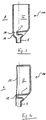
- Fig. 1 shows a receiving device according to the invention a first embodiment in a filling phase.
- the receiving device 100 has in its interior I a Fluidschwallum effetselement having a Umströmungsharm 1.
- the bypass body 1 is arranged within a transition region 3 of the receiving device 100 between an inflow channel 5 and a useful region 7 of the receiving device 100.
- the transition region 3 of the receiving device 100 allows a meaningful transition between the relatively small fluid cross section of the inflow channel 5 and the relatively large cross section of the receiving device 100, such as the manufacturability of the receiving device 100 and the inflow channel 5 in one piece, a good self-emptying of the receiving device 100 also at obliquely arranged arrangement of the receiving device 100, the integration of a Kanalver gleichventils directly at the transition of the inflow channel 5 in the receiving device and the like.
- measuring devices for detecting a water level of the fluids contained in the receiving device 100 may be provided. Such measuring devices can be configured optimized for this purpose of detection.
- the bypass body 1 is preferably disposed within the transition region 3, also to use the space of the transition region 3.
- the useful area 7 of the receiving device 100 can satisfy requirements, for example a favorable ratio between space requirement and filling volume of the receiving device 100, a favorable measurability of the filling volume of the receiving device 100 or the fluids contained therein or other sizes (such as by means of transparency of the fluids in the receiving device 100 ), a low wetted surface compared to the filling volume, good wetting and Entnetzungs , a good flow behavior of the fluids and the like.
- the fluid surge flowing into the receiving device 100 strikes a front 11 of the bypass body 1 and is divided into two partial fluid surge.
- the partial fluid bilges are guided past a right side flank 13 and a left side flank 15, respectively.
- the flow body 1 can, as in Fig. 1 shown to have an elliptical cross-section.
- the flow body 1 is, as in Fig. 1 shown disposed substantially symmetrically in the inflow zone of the fluid surge.
- both the width and the height (extension in the direction of flow in the direction of the double arrow) of the flow body 1 may be directed to give the Umströmungs stresses 1 as small as possible in all directions spatial dimension.
- These minimally small dimensions of the bypass body 1 can preferably contribute to ensuring the lowest possible loss of usable filling volume of the receiving device 100 and / or to reduce the surface of the receiving device 100 to be wiped and de-entangled.
- a smaller surface can advantageously lead to lower adhesion possibilities for small gas bubbles.
- a lesser surface area may generally reduce the chemical and / or physical reactivity of the fluids with the material of the receiver 100 and / or with the gas in the receiver. For example, this can advantageously lead to an improved haemocompatibility and / or reduced blood coagulation tendency through less air and less foreign surface.
- a smaller surface area, in relation to the maximum filling volume, advantageously allows the fluids to flow into and out of the receiving device 100 in a more complete and reproducible manner since smaller residual quantities can adhere to this surface.
- the accurate measurement of the filling volume based on the level can be facilitated.
- the exchange of fluids between the filling / emptying cycles can advantageously be more complete.
- the mixing of the fluid charges can, what can be sought procedurally in many cases, especially with regard to improved hemocompatibility by avoiding blood adhesion and reduction of blood residence time to foreign surfaces can be achieved.
- the minimum dimensions of the bypass body 1 can be determined experimentally and selected so that the desired effect of calming the flows and the level surface as well as the minimal generation and introduction of gas into the fluids flowing into the receiver 100 can just be achieved.
- the minimum possible dimensions may depend on the shape and / or the average flow velocity in the inflow passage 5, the composition and viscosity of the inflowing fluids, the material and the surface structure of the sidewalls of the inflow passage 5, the receiver 100 and / or the bypass body 1, of FIG the design of the transition region 3, of the geometric connection of the Umströmungs stressess 1 to the receiving device 100, of the possible pulsation and the permissible volume flow range of the inflowing fluids and / or of all geometric factors on the currents in the nearer and somewhat wider environment (to about depend on ten times the cross section of the inflow channel 5) of the Umströmungs stresses 1.
- the desired effect of the flow calming can already be achieved with surprisingly small dimensions of the flow body 1 in the range of sizes smaller than the mean flow cross section in the inflow channel 5.
- the bypass body 1 could be curved in all dimensions, such as a sphere or an ellipsoid.
- the joint and / or dead space free connection to the receiving device 100 and / or the In order to achieve cost-effective manufacturability from one piece with the receiving device 100, the flow-around body 1 in a particularly preferred embodiment can have only one flow cross-section curved in two spatial directions. For example, it may preferably have a substantially prismatic design, as described below in FIG 3 and 4 is shown.
- a flow calming of the fluid surge can take place.
- the mechanism of action of the flow calming can - compared to other solutions - rely more on a targeted self-surge extinction. Overall, it can represent a combination of several flow effects.
- a slowing down of the flow of fluid surge can be achieved a) by channel expansion of the inflow duct 5 between the Umströmungsterrorism 5 and the walls or side walls of the transition region 3 and / or b) by a division into at least two equal and each half as large opposite flowing partial flows or partial fluid surge and / or c) by a division of the respective Operafluidschwalle in at least two other partial fluid surge with opposite momentum or spin by adhesion to the Umströmungs endeavor 1 on one side and to the respective side wall of the receiving device 100 on the other side and / or d) by a collision and mutual extinction of the opposite equal flow and swirl pulses on the opposite side, ie the back 17 of the Umströmungs emotionss 1 and / or e) by meeting and extinguishing the opposite equal sized St Rung pulses in the areas between the UmströmungsAvem 1 and a side wall of the receiving device 100 right and left of the Umströmungs emotionss 1 and / or b
- the bypass body 1 may have a circular, elliptical, paraboloidal or Gothic pointed cross section.
- the bypass body 1 may have an asymmetrical cross section with respect to the sides facing and away from the inflow passage 5.
- the symmetrical design of the geometry on the right side flank 13 and the left side flank 15 may be essential to the proper functioning of the impulse division and self-extinction operations.
- Fig. 2 shows the receiving device 100 according to the invention in a discharge phase in which the fluids are shortly before the detachment from the flow body 1.
- the inflow channel 5 acts in this case as an outflow channel.
- the right-left symmetrical design of the Umströmungs emotionss 1 and / or the remaining receptacle 100 in conjunction with the gradual extension of the flow cross-section of the outflow channel before and behind the narrowest passage zone right and left of Umströmungs emotionss 1 help that the compact Zone of the main fluid as long as possible with the thin fluid zones of the residual wetting with the Umströmungs endeavor 1 and / or with the side walls of the receiving device 100 remains in contact.
- a maximum amount of residual liquid is entrained with the main flow, before it comes to the detachment and the whereabouts of residual films on the surfaces of the Umströmungs emotionss 1 and the side walls of the receiving device 100.
- Fig. 3 shows an embodiment of the receiving device according to the invention in longitudinal section, in which the receiving device 100, the inflow passage 5 and the bypass body 1 are injection-molded in one piece.
- the circulating body 1 is not connected to the front side with an opposite wall 19, but instead has a gap 21, which is sufficiently large for avoiding flow dead zones and / or air pockets, to the wall 19.
- Fig. 4 shows a further embodiment of the present receiving device 100 in longitudinal section, in which the overall arrangement is carried out in the typical cassette design.
- channels such as an inflow channel 5, and / or chambers in an injection molded part can be made substantially open on one side.
- the foil as in Fig. 4 shown by welding and / or pressing on an end face 25 of the Umströmungs stressess 1 are applied with direct contact to this. With such an arrangement, a gap can be deliberately avoided.
- Fig. 5 shows a front view of an external functional device according to the invention, which at the surface, on the in Fig. 5 is provided with a cover 23 is provided.
- the external functional device is here exemplarily designed as a blood treatment cassette 1000 with chambers, channels, valves and the like.
- the cover device 23 covers a front side of the blood treatment cassette 1000. It is exemplified as a film.
- the blood treatment cassette 1000 may be at least the same as in Fig. 5 shown front to a blood treatment device (in Fig. 5 not shown).
- the blood treatment cassette 1000 has the receiving device 100 according to the invention.
- the receiving device 100 extends from the in Figure 5 shown front view backwards in the plane of the drawing Fig. 5 into it.
- the course of the wall 19 of the receiving device 100 away from the viewer is indicated by the lines shown in the radial direction.
- the bypass body 1 extends from its base toward the viewer of the Fig. 1 to.
- the receiving device 100 has the bypass body 1.
- Figure 5 are particularly well from the flow body 1, the end face 25 and a lower lying in the drawing plane saddle-shaped connecting portion 12 between the Umströmungsharm 1 and the wall 19 to recognize.
- the receiving device 100 has a phantom valve 27 at its lower end, ie at the inflow region.
- the circulating body 1 is flown in the receiving device 100 via the phantom valve 27, wherein blood from the underlying chamber (eg a venous blood chamber, as in the filed by the applicant of the present application to the DPMA on June 10, 2009 application 10 2009 024 465 A1 with the title "air separator, external functional device , blood circulation and treatment device " ) is introduced into the receiving device 100 through the phantom valve 27 formed by the cover device 23 and a web section.
- the underlying chamber eg a venous blood chamber, as in the filed by the applicant of the present application to the DPMA on June 10, 2009 application 10 2009 024 465 A1 with the title "air separator, external functional device , blood circulation and treatment device "
- Fig. 6 shows the blood treatment cassette 1000 of Fig. 5 , wherein the covering device 23 on the left edge of the blood treatment cassette 1000 as well as above and below erförend cut and can be seen unfolded to the right.
- Fig. 6 shows the elements to be recognized in more detail in the interior of the blood treatment cassette 1000 after the foil has been cut open.
- Fig. 7 shows the blood treatment cassette 1000 from its back.
- the blood treatment cassette 1000 is coupled to the blood treatment device, a viewer will look at this rear side upon opening a door of the blood treatment device for removing the blood treatment cassette 1000.
Landscapes
- Health & Medical Sciences (AREA)
- Heart & Thoracic Surgery (AREA)
- Vascular Medicine (AREA)
- Biomedical Technology (AREA)
- Engineering & Computer Science (AREA)
- Anesthesiology (AREA)
- Cardiology (AREA)
- Hematology (AREA)
- Life Sciences & Earth Sciences (AREA)
- Animal Behavior & Ethology (AREA)
- General Health & Medical Sciences (AREA)
- Public Health (AREA)
- Veterinary Medicine (AREA)
- External Artificial Organs (AREA)
- Physical Or Chemical Processes And Apparatus (AREA)
Applications Claiming Priority (4)
| Application Number | Priority Date | Filing Date | Title |
|---|---|---|---|
| DE102009018664A DE102009018664A1 (de) | 2009-04-23 | 2009-04-23 | Externe Funktionseinrichtung, Blutbehandlungsvorrichtung zum Aufnehmen einer erfindungsgemäßen externen Funktionseinrichtung, sowie Verfahren |
| US18560709P | 2009-06-10 | 2009-06-10 | |
| DE102009024466A DE102009024466A1 (de) | 2009-06-10 | 2009-06-10 | Aufnahmeeinrichtung zum Aufnehmen von medizinischen Fluiden sowie externe Funktionseinrichtung und medizinische Behandlungsvorrichtung |
| PCT/EP2010/002294 WO2010121740A1 (de) | 2009-04-23 | 2010-04-14 | Aufnahmeeinrichtung zum aufnehmen von medizinischen fluiden sowie externe funktionseinrichtung und medizinische behandlungsvorrichtung |
Publications (2)
| Publication Number | Publication Date |
|---|---|
| EP2421580A1 EP2421580A1 (de) | 2012-02-29 |
| EP2421580B1 true EP2421580B1 (de) | 2019-12-04 |
Family
ID=42310238
Family Applications (1)
| Application Number | Title | Priority Date | Filing Date |
|---|---|---|---|
| EP10713854.7A Active EP2421580B1 (de) | 2009-04-23 | 2010-04-14 | Aufnahmeeinrichtung zum aufnehmen von medizinischen fluiden sowie externe funktionseinrichtung und medizinische behandlungsvorrichtung |
Country Status (6)
| Country | Link |
|---|---|
| US (1) | US9925324B2 (https=) |
| EP (1) | EP2421580B1 (https=) |
| JP (2) | JP2012524557A (https=) |
| CN (1) | CN102458504B (https=) |
| IN (1) | IN2011KN04778A (https=) |
| WO (1) | WO2010121740A1 (https=) |
Families Citing this family (5)
| Publication number | Priority date | Publication date | Assignee | Title |
|---|---|---|---|---|
| DE102014103491A1 (de) * | 2014-03-14 | 2015-09-17 | Fresenius Medical Care Deutschland Gmbh | Blutbehandlungskassette mit Folienventil und unelastischem Abstandhalter sowie Blutbehandlungsvorrichtung |
| WO2015156299A1 (ja) * | 2014-04-07 | 2015-10-15 | キョーラク株式会社 | 中空成形品 |
| JP6347139B2 (ja) * | 2014-04-07 | 2018-06-27 | キョーラク株式会社 | 中空成形品 |
| DE102014119106A1 (de) | 2014-12-18 | 2016-07-07 | B. Braun Avitum Ag | Konzentratbehälter für eine extrakorporale Blutbehandlungsmaschine, sowie Konzentrat-Zuführsystem für eine extrakorporale Blutbehandlungsmaschine |
| JP7597485B2 (ja) * | 2020-12-22 | 2024-12-10 | 旭化成メディカル株式会社 | 計量チャンバー及び液体処理装置 |
Citations (1)
| Publication number | Priority date | Publication date | Assignee | Title |
|---|---|---|---|---|
| US20050230292A1 (en) * | 2002-06-04 | 2005-10-20 | Josef Beden | Device for treating a medical liquid |
Family Cites Families (22)
| Publication number | Priority date | Publication date | Assignee | Title |
|---|---|---|---|---|
| JPH0112833Y2 (https=) | 1986-07-09 | 1989-04-14 | ||
| JPH0399689A (ja) | 1989-09-14 | 1991-04-24 | Seiko Epson Corp | ゲーム用icカード |
| US6013060A (en) * | 1997-11-19 | 2000-01-11 | Woodard; Robert W. | Intravenous liquid flow regulator |
| DE19814695C2 (de) * | 1998-04-01 | 2001-09-13 | Fresenius Medical Care De Gmbh | Kassette zur Förderung von Flüssigkeiten, insbesondere Dialyseflüssigkeiten, Dialysegerät und Verfahren zum Fördern, Bilanzieren, Dosieren und Beheizen eines medizinischen Fluids |
| US7238164B2 (en) | 2002-07-19 | 2007-07-03 | Baxter International Inc. | Systems, methods and apparatuses for pumping cassette-based therapies |
| JP3099689U (ja) | 2003-08-05 | 2004-04-15 | 興和工業株式会社 | ジョイントポール |
| US7279031B1 (en) * | 2003-11-25 | 2007-10-09 | Wright David W | Emboli elimination apparatus |
| US20060009727A1 (en) * | 2004-04-08 | 2006-01-12 | Chf Solutions Inc. | Method and apparatus for an extracorporeal control of blood glucose |
| ITMO20040235A1 (it) * | 2004-09-17 | 2004-12-17 | Gambro Lundia Ab | Camera snague per un circuito extraxorporeo. |
| US7279903B2 (en) | 2005-05-02 | 2007-10-09 | Invensys Systems, Inc. | Non-metallic flow-through electrodeless conductivity sensor with leak and temperature detection |
| CN101203326A (zh) * | 2005-06-29 | 2008-06-18 | 药物混合系统股份公司 | 用于排气和去除配给器械的无用材料的方法和装置 |
| EP1896192A1 (en) * | 2005-06-29 | 2008-03-12 | Medmix Systems AG | Method and device for venting and eliminating unwanted material of a dispensing appliance |
| EP2114510A4 (en) * | 2006-12-19 | 2014-04-16 | Arnold J Lande | CHRONIC ACCESS SYSTEM FOR EXTRACORPOREAL TREATMENT OF BLOOD WITH A CONTINUOUSLY PORTABLE HEMODIALYSER |
| US7892332B2 (en) | 2007-10-01 | 2011-02-22 | Baxter International Inc. | Dialysis systems having air traps with internal structures to enhance air removal |
| US7871462B2 (en) * | 2007-10-01 | 2011-01-18 | Baxter International Inc. | Dialysis systems having air separation chambers with internal structures to enhance air removal |
| US7892331B2 (en) | 2007-10-01 | 2011-02-22 | Baxter International Inc. | Dialysis systems having air separation chambers with internal structures to enhance air removal |
| DE102009012632A1 (de) | 2009-03-10 | 2010-09-23 | Fresenius Medical Care Deutschland Gmbh | Abdichtungseinrichtung zum Abdichten eines Volumens einer medizinischen Behandlungsanordnung gegen ein weiteres Volumen sowie Anordnung und Verfahren |
| DE102009024465B4 (de) | 2009-06-10 | 2015-03-05 | Fresenius Medical Care Deutschland Gmbh | Blutkassette mit Luftabscheider, Blutkreislauf sowie Behandlungsvorrichtung |
| DE102009024468A1 (de) | 2009-06-10 | 2010-12-16 | Fresenius Medical Care Deutschland Gmbh | Externe Funktionseinrichtung, Blutbehandlungsvorrichtung zum Aufnehmen einer erfindungsgemäßen externen Funktionseinrichtung, sowie Verfahren |
| DE102009018664A1 (de) | 2009-04-23 | 2010-10-28 | Fresenius Medical Care Deutschland Gmbh | Externe Funktionseinrichtung, Blutbehandlungsvorrichtung zum Aufnehmen einer erfindungsgemäßen externen Funktionseinrichtung, sowie Verfahren |
| EP2421584B1 (de) * | 2009-04-23 | 2016-04-13 | Fresenius Medical Care Deutschland GmbH | Luftabscheider, externe funktionseinrichtung, blutkreislauf sowie behandlungsvorrichtung |
| US8506684B2 (en) * | 2010-12-15 | 2013-08-13 | Fresenius Medical Care Holdings, Inc. | Gas release devices for extracorporeal fluid circuits and related methods |
-
2010
- 2010-04-14 IN IN4778KON2011 patent/IN2011KN04778A/en unknown
- 2010-04-14 EP EP10713854.7A patent/EP2421580B1/de active Active
- 2010-04-14 WO PCT/EP2010/002294 patent/WO2010121740A1/de not_active Ceased
- 2010-04-14 CN CN201080027669.XA patent/CN102458504B/zh active Active
- 2010-04-14 JP JP2012506374A patent/JP2012524557A/ja active Pending
- 2010-04-23 US US12/766,394 patent/US9925324B2/en not_active Expired - Fee Related
-
2015
- 2015-01-13 JP JP2015004186A patent/JP5938810B2/ja active Active
Patent Citations (1)
| Publication number | Priority date | Publication date | Assignee | Title |
|---|---|---|---|---|
| US20050230292A1 (en) * | 2002-06-04 | 2005-10-20 | Josef Beden | Device for treating a medical liquid |
Also Published As
| Publication number | Publication date |
|---|---|
| CN102458504B (zh) | 2016-04-06 |
| JP2015134163A (ja) | 2015-07-27 |
| JP2012524557A (ja) | 2012-10-18 |
| CN102458504A (zh) | 2012-05-16 |
| JP5938810B2 (ja) | 2016-06-22 |
| IN2011KN04778A (https=) | 2015-07-10 |
| WO2010121740A1 (de) | 2010-10-28 |
| US20100294398A1 (en) | 2010-11-25 |
| EP2421580A1 (de) | 2012-02-29 |
| US9925324B2 (en) | 2018-03-27 |
Similar Documents
| Publication | Publication Date | Title |
|---|---|---|
| EP2421580B1 (de) | Aufnahmeeinrichtung zum aufnehmen von medizinischen fluiden sowie externe funktionseinrichtung und medizinische behandlungsvorrichtung | |
| DE102009024465B4 (de) | Blutkassette mit Luftabscheider, Blutkreislauf sowie Behandlungsvorrichtung | |
| EP2366984B1 (de) | Vorrichtung zur Messung verschäumter Medien | |
| WO2005042137A3 (en) | Multilayer hydrodynamic sheath flow structure | |
| DE102009048378B3 (de) | Mikrofluidische Struktur | |
| WO2014006001A1 (de) | Durchflussmesser | |
| DE2851176A1 (de) | Gaswaschanlage und verfahren zum betrieb derselben | |
| DE102011084027A1 (de) | Schnellkupplungsvorrichtung | |
| EP2654823A1 (de) | Kammer für ein blutbehandlungssystem, verwendung der kammer, blutschlauchsystem sowie blutbehandlungssystem | |
| DE102009024466A1 (de) | Aufnahmeeinrichtung zum Aufnehmen von medizinischen Fluiden sowie externe Funktionseinrichtung und medizinische Behandlungsvorrichtung | |
| WO2013034575A1 (de) | Einfüllstutzen für einen flüssigkeitsvorratsbehälter eines kraftfahrzeugs mit einem integrierten entlüftungskanal | |
| WO1996036375A1 (de) | Vorrichtung zur bestrahlung von körperflüssigkeiten mit uv-licht | |
| CH710814A2 (de) | Vorrichtung zur Entgasung einer Flüssigkeit. | |
| EP3139138A1 (de) | Messarmatur für einen durchflussmesser | |
| EP3357524B1 (de) | Luftabscheider mit zwangszirkulation | |
| DE2735955C2 (de) | Dosiervorrichtung für Übertragungsgeräte der Infusions- oder Transfusionstechnik | |
| DE102006059808B3 (de) | Strahlformer | |
| WO2016152934A1 (ja) | 混合用チャンバ | |
| EP0417776A2 (de) | Vorrichtung zum Ansaugen von Zusatzstoffen in eine Flüssigkeitsströmung | |
| DE10235033B4 (de) | Durchflußmesser | |
| DE19531751A1 (de) | Vorrichtung zur Bestrahlung von Körperflüssigkeiten mit UV-Licht | |
| DE4215565C2 (de) | Abscheider | |
| DE202013101223U1 (de) | Füllorgan zum Befüllen eines Behälters in einer Getränkeabfüllanlage | |
| DE19807664A1 (de) | Schwimmerventil für ein Sauggerät | |
| EP1303701B1 (de) | Pumpe |
Legal Events
| Date | Code | Title | Description |
|---|---|---|---|
| PUAI | Public reference made under article 153(3) epc to a published international application that has entered the european phase |
Free format text: ORIGINAL CODE: 0009012 |
|
| 17P | Request for examination filed |
Effective date: 20111116 |
|
| AK | Designated contracting states |
Kind code of ref document: A1 Designated state(s): AT BE BG CH CY CZ DE DK EE ES FI FR GB GR HR HU IE IS IT LI LT LU LV MC MK MT NL NO PL PT RO SE SI SK SM TR |
|
| DAX | Request for extension of the european patent (deleted) | ||
| STAA | Information on the status of an ep patent application or granted ep patent |
Free format text: STATUS: EXAMINATION IS IN PROGRESS |
|
| 17Q | First examination report despatched |
Effective date: 20161129 |
|
| GRAP | Despatch of communication of intention to grant a patent |
Free format text: ORIGINAL CODE: EPIDOSNIGR1 |
|
| STAA | Information on the status of an ep patent application or granted ep patent |
Free format text: STATUS: GRANT OF PATENT IS INTENDED |
|
| INTG | Intention to grant announced |
Effective date: 20190128 |
|
| GRAS | Grant fee paid |
Free format text: ORIGINAL CODE: EPIDOSNIGR3 |
|
| GRAJ | Information related to disapproval of communication of intention to grant by the applicant or resumption of examination proceedings by the epo deleted |
Free format text: ORIGINAL CODE: EPIDOSDIGR1 |
|
| GRAL | Information related to payment of fee for publishing/printing deleted |
Free format text: ORIGINAL CODE: EPIDOSDIGR3 |
|
| STAA | Information on the status of an ep patent application or granted ep patent |
Free format text: STATUS: EXAMINATION IS IN PROGRESS |
|
| GRAP | Despatch of communication of intention to grant a patent |
Free format text: ORIGINAL CODE: EPIDOSNIGR1 |
|
| STAA | Information on the status of an ep patent application or granted ep patent |
Free format text: STATUS: GRANT OF PATENT IS INTENDED |
|
| INTC | Intention to grant announced (deleted) | ||
| INTG | Intention to grant announced |
Effective date: 20190704 |
|
| GRAA | (expected) grant |
Free format text: ORIGINAL CODE: 0009210 |
|
| STAA | Information on the status of an ep patent application or granted ep patent |
Free format text: STATUS: THE PATENT HAS BEEN GRANTED |
|
| AK | Designated contracting states |
Kind code of ref document: B1 Designated state(s): AT BE BG CH CY CZ DE DK EE ES FI FR GB GR HR HU IE IS IT LI LT LU LV MC MK MT NL NO PL PT RO SE SI SK SM TR |
|
| REG | Reference to a national code |
Ref country code: GB Ref legal event code: FG4D Free format text: NOT ENGLISH |
|
| REG | Reference to a national code |
Ref country code: CH Ref legal event code: EP |
|
| REG | Reference to a national code |
Ref country code: AT Ref legal event code: REF Ref document number: 1208596 Country of ref document: AT Kind code of ref document: T Effective date: 20191215 |
|
| REG | Reference to a national code |
Ref country code: DE Ref legal event code: R096 Ref document number: 502010016394 Country of ref document: DE |
|
| REG | Reference to a national code |
Ref country code: IE Ref legal event code: FG4D Free format text: LANGUAGE OF EP DOCUMENT: GERMAN |
|
| REG | Reference to a national code |
Ref country code: SE Ref legal event code: TRGR |
|
| REG | Reference to a national code |
Ref country code: NL Ref legal event code: MP Effective date: 20191204 |
|
| REG | Reference to a national code |
Ref country code: LT Ref legal event code: MG4D |
|
| PG25 | Lapsed in a contracting state [announced via postgrant information from national office to epo] |
Ref country code: FI Free format text: LAPSE BECAUSE OF FAILURE TO SUBMIT A TRANSLATION OF THE DESCRIPTION OR TO PAY THE FEE WITHIN THE PRESCRIBED TIME-LIMIT Effective date: 20191204 Ref country code: BG Free format text: LAPSE BECAUSE OF FAILURE TO SUBMIT A TRANSLATION OF THE DESCRIPTION OR TO PAY THE FEE WITHIN THE PRESCRIBED TIME-LIMIT Effective date: 20200304 Ref country code: GR Free format text: LAPSE BECAUSE OF FAILURE TO SUBMIT A TRANSLATION OF THE DESCRIPTION OR TO PAY THE FEE WITHIN THE PRESCRIBED TIME-LIMIT Effective date: 20200305 Ref country code: LV Free format text: LAPSE BECAUSE OF FAILURE TO SUBMIT A TRANSLATION OF THE DESCRIPTION OR TO PAY THE FEE WITHIN THE PRESCRIBED TIME-LIMIT Effective date: 20191204 Ref country code: NO Free format text: LAPSE BECAUSE OF FAILURE TO SUBMIT A TRANSLATION OF THE DESCRIPTION OR TO PAY THE FEE WITHIN THE PRESCRIBED TIME-LIMIT Effective date: 20200304 Ref country code: LT Free format text: LAPSE BECAUSE OF FAILURE TO SUBMIT A TRANSLATION OF THE DESCRIPTION OR TO PAY THE FEE WITHIN THE PRESCRIBED TIME-LIMIT Effective date: 20191204 Ref country code: ES Free format text: LAPSE BECAUSE OF FAILURE TO SUBMIT A TRANSLATION OF THE DESCRIPTION OR TO PAY THE FEE WITHIN THE PRESCRIBED TIME-LIMIT Effective date: 20191204 |
|
| PGFP | Annual fee paid to national office [announced via postgrant information from national office to epo] |
Ref country code: SE Payment date: 20200320 Year of fee payment: 11 |
|
| PG25 | Lapsed in a contracting state [announced via postgrant information from national office to epo] |
Ref country code: HR Free format text: LAPSE BECAUSE OF FAILURE TO SUBMIT A TRANSLATION OF THE DESCRIPTION OR TO PAY THE FEE WITHIN THE PRESCRIBED TIME-LIMIT Effective date: 20191204 |
|
| PG25 | Lapsed in a contracting state [announced via postgrant information from national office to epo] |
Ref country code: EE Free format text: LAPSE BECAUSE OF FAILURE TO SUBMIT A TRANSLATION OF THE DESCRIPTION OR TO PAY THE FEE WITHIN THE PRESCRIBED TIME-LIMIT Effective date: 20191204 Ref country code: NL Free format text: LAPSE BECAUSE OF FAILURE TO SUBMIT A TRANSLATION OF THE DESCRIPTION OR TO PAY THE FEE WITHIN THE PRESCRIBED TIME-LIMIT Effective date: 20191204 Ref country code: PT Free format text: LAPSE BECAUSE OF FAILURE TO SUBMIT A TRANSLATION OF THE DESCRIPTION OR TO PAY THE FEE WITHIN THE PRESCRIBED TIME-LIMIT Effective date: 20200429 Ref country code: CZ Free format text: LAPSE BECAUSE OF FAILURE TO SUBMIT A TRANSLATION OF THE DESCRIPTION OR TO PAY THE FEE WITHIN THE PRESCRIBED TIME-LIMIT Effective date: 20191204 Ref country code: RO Free format text: LAPSE BECAUSE OF FAILURE TO SUBMIT A TRANSLATION OF THE DESCRIPTION OR TO PAY THE FEE WITHIN THE PRESCRIBED TIME-LIMIT Effective date: 20191204 |
|
| PG25 | Lapsed in a contracting state [announced via postgrant information from national office to epo] |
Ref country code: SM Free format text: LAPSE BECAUSE OF FAILURE TO SUBMIT A TRANSLATION OF THE DESCRIPTION OR TO PAY THE FEE WITHIN THE PRESCRIBED TIME-LIMIT Effective date: 20191204 Ref country code: SK Free format text: LAPSE BECAUSE OF FAILURE TO SUBMIT A TRANSLATION OF THE DESCRIPTION OR TO PAY THE FEE WITHIN THE PRESCRIBED TIME-LIMIT Effective date: 20191204 Ref country code: IS Free format text: LAPSE BECAUSE OF FAILURE TO SUBMIT A TRANSLATION OF THE DESCRIPTION OR TO PAY THE FEE WITHIN THE PRESCRIBED TIME-LIMIT Effective date: 20200404 |
|
| REG | Reference to a national code |
Ref country code: DE Ref legal event code: R097 Ref document number: 502010016394 Country of ref document: DE |
|
| PLBE | No opposition filed within time limit |
Free format text: ORIGINAL CODE: 0009261 |
|
| STAA | Information on the status of an ep patent application or granted ep patent |
Free format text: STATUS: NO OPPOSITION FILED WITHIN TIME LIMIT |
|
| PG25 | Lapsed in a contracting state [announced via postgrant information from national office to epo] |
Ref country code: DK Free format text: LAPSE BECAUSE OF FAILURE TO SUBMIT A TRANSLATION OF THE DESCRIPTION OR TO PAY THE FEE WITHIN THE PRESCRIBED TIME-LIMIT Effective date: 20191204 |
|
| 26N | No opposition filed |
Effective date: 20200907 |
|
| PG25 | Lapsed in a contracting state [announced via postgrant information from national office to epo] |
Ref country code: MC Free format text: LAPSE BECAUSE OF FAILURE TO SUBMIT A TRANSLATION OF THE DESCRIPTION OR TO PAY THE FEE WITHIN THE PRESCRIBED TIME-LIMIT Effective date: 20191204 Ref country code: PL Free format text: LAPSE BECAUSE OF FAILURE TO SUBMIT A TRANSLATION OF THE DESCRIPTION OR TO PAY THE FEE WITHIN THE PRESCRIBED TIME-LIMIT Effective date: 20191204 Ref country code: SI Free format text: LAPSE BECAUSE OF FAILURE TO SUBMIT A TRANSLATION OF THE DESCRIPTION OR TO PAY THE FEE WITHIN THE PRESCRIBED TIME-LIMIT Effective date: 20191204 |
|
| REG | Reference to a national code |
Ref country code: CH Ref legal event code: PL |
|
| PG25 | Lapsed in a contracting state [announced via postgrant information from national office to epo] |
Ref country code: LU Free format text: LAPSE BECAUSE OF NON-PAYMENT OF DUE FEES Effective date: 20200414 Ref country code: CH Free format text: LAPSE BECAUSE OF NON-PAYMENT OF DUE FEES Effective date: 20200430 Ref country code: LI Free format text: LAPSE BECAUSE OF NON-PAYMENT OF DUE FEES Effective date: 20200430 |
|
| REG | Reference to a national code |
Ref country code: BE Ref legal event code: MM Effective date: 20200430 |
|
| PG25 | Lapsed in a contracting state [announced via postgrant information from national office to epo] |
Ref country code: BE Free format text: LAPSE BECAUSE OF NON-PAYMENT OF DUE FEES Effective date: 20200430 |
|
| PG25 | Lapsed in a contracting state [announced via postgrant information from national office to epo] |
Ref country code: IE Free format text: LAPSE BECAUSE OF NON-PAYMENT OF DUE FEES Effective date: 20200414 |
|
| REG | Reference to a national code |
Ref country code: AT Ref legal event code: MM01 Ref document number: 1208596 Country of ref document: AT Kind code of ref document: T Effective date: 20200414 |
|
| PG25 | Lapsed in a contracting state [announced via postgrant information from national office to epo] |
Ref country code: AT Free format text: LAPSE BECAUSE OF NON-PAYMENT OF DUE FEES Effective date: 20200414 |
|
| REG | Reference to a national code |
Ref country code: SE Ref legal event code: EUG |
|
| PG25 | Lapsed in a contracting state [announced via postgrant information from national office to epo] |
Ref country code: SE Free format text: LAPSE BECAUSE OF NON-PAYMENT OF DUE FEES Effective date: 20210415 |
|
| PG25 | Lapsed in a contracting state [announced via postgrant information from national office to epo] |
Ref country code: TR Free format text: LAPSE BECAUSE OF FAILURE TO SUBMIT A TRANSLATION OF THE DESCRIPTION OR TO PAY THE FEE WITHIN THE PRESCRIBED TIME-LIMIT Effective date: 20191204 Ref country code: MT Free format text: LAPSE BECAUSE OF FAILURE TO SUBMIT A TRANSLATION OF THE DESCRIPTION OR TO PAY THE FEE WITHIN THE PRESCRIBED TIME-LIMIT Effective date: 20191204 Ref country code: CY Free format text: LAPSE BECAUSE OF FAILURE TO SUBMIT A TRANSLATION OF THE DESCRIPTION OR TO PAY THE FEE WITHIN THE PRESCRIBED TIME-LIMIT Effective date: 20191204 |
|
| PG25 | Lapsed in a contracting state [announced via postgrant information from national office to epo] |
Ref country code: MK Free format text: LAPSE BECAUSE OF FAILURE TO SUBMIT A TRANSLATION OF THE DESCRIPTION OR TO PAY THE FEE WITHIN THE PRESCRIBED TIME-LIMIT Effective date: 20191204 |
|
| P01 | Opt-out of the competence of the unified patent court (upc) registered |
Effective date: 20230602 |
|
| PGFP | Annual fee paid to national office [announced via postgrant information from national office to epo] |
Ref country code: DE Payment date: 20250319 Year of fee payment: 16 |
|
| PGFP | Annual fee paid to national office [announced via postgrant information from national office to epo] |
Ref country code: GB Payment date: 20260320 Year of fee payment: 17 |
|
| PGFP | Annual fee paid to national office [announced via postgrant information from national office to epo] |
Ref country code: IT Payment date: 20260319 Year of fee payment: 17 |
|
| PGFP | Annual fee paid to national office [announced via postgrant information from national office to epo] |
Ref country code: FR Payment date: 20260319 Year of fee payment: 17 |