EP2421345A2 - Anpassbares Automationssteuerungsmodul mit integriertem Leistungsbusverteiler - Google Patents
Anpassbares Automationssteuerungsmodul mit integriertem Leistungsbusverteiler Download PDFInfo
- Publication number
- EP2421345A2 EP2421345A2 EP11178345A EP11178345A EP2421345A2 EP 2421345 A2 EP2421345 A2 EP 2421345A2 EP 11178345 A EP11178345 A EP 11178345A EP 11178345 A EP11178345 A EP 11178345A EP 2421345 A2 EP2421345 A2 EP 2421345A2
- Authority
- EP
- European Patent Office
- Prior art keywords
- adaptable
- automation control
- control component
- activation mechanism
- power bus
- Prior art date
- Legal status (The legal status is an assumption and is not a legal conclusion. Google has not performed a legal analysis and makes no representation as to the accuracy of the status listed.)
- Granted
Links
- 230000007246 mechanism Effects 0.000 claims abstract description 76
- 238000009826 distribution Methods 0.000 claims abstract description 72
- 230000004913 activation Effects 0.000 claims abstract description 69
- 238000004891 communication Methods 0.000 claims abstract description 15
- 230000008878 coupling Effects 0.000 claims abstract description 12
- 238000010168 coupling process Methods 0.000 claims abstract description 12
- 238000005859 coupling reaction Methods 0.000 claims abstract description 12
- 238000000034 method Methods 0.000 claims description 48
- 230000013011 mating Effects 0.000 claims description 10
- 230000002441 reversible effect Effects 0.000 claims description 7
- 238000004519 manufacturing process Methods 0.000 claims description 4
- 230000008569 process Effects 0.000 description 26
- 230000006870 function Effects 0.000 description 21
- 238000012806 monitoring device Methods 0.000 description 21
- 238000012544 monitoring process Methods 0.000 description 16
- 238000011144 upstream manufacturing Methods 0.000 description 13
- 230000000153 supplemental effect Effects 0.000 description 6
- 230000008859 change Effects 0.000 description 4
- 238000010586 diagram Methods 0.000 description 3
- 230000003213 activating effect Effects 0.000 description 2
- 239000012190 activator Substances 0.000 description 2
- 230000005540 biological transmission Effects 0.000 description 2
- 238000006243 chemical reaction Methods 0.000 description 2
- 230000009849 deactivation Effects 0.000 description 2
- 230000002427 irreversible effect Effects 0.000 description 2
- 238000012423 maintenance Methods 0.000 description 2
- 238000012986 modification Methods 0.000 description 2
- 230000004048 modification Effects 0.000 description 2
- 238000012546 transfer Methods 0.000 description 2
- 230000000007 visual effect Effects 0.000 description 2
- 230000009471 action Effects 0.000 description 1
- 230000003044 adaptive effect Effects 0.000 description 1
- 238000004458 analytical method Methods 0.000 description 1
- 230000003190 augmentative effect Effects 0.000 description 1
- 230000008901 benefit Effects 0.000 description 1
- 230000002457 bidirectional effect Effects 0.000 description 1
- 230000001276 controlling effect Effects 0.000 description 1
- 238000013461 design Methods 0.000 description 1
- 238000005315 distribution function Methods 0.000 description 1
- 238000009429 electrical wiring Methods 0.000 description 1
- 238000005516 engineering process Methods 0.000 description 1
- 239000000463 material Substances 0.000 description 1
- 238000004801 process automation Methods 0.000 description 1
- 238000004886 process control Methods 0.000 description 1
- 238000012545 processing Methods 0.000 description 1
- 230000007363 regulatory process Effects 0.000 description 1
- 230000004044 response Effects 0.000 description 1
- 230000000087 stabilizing effect Effects 0.000 description 1
- 230000001960 triggered effect Effects 0.000 description 1
Images


Classifications
-
- H—ELECTRICITY
- H05—ELECTRIC TECHNIQUES NOT OTHERWISE PROVIDED FOR
- H05K—PRINTED CIRCUITS; CASINGS OR CONSTRUCTIONAL DETAILS OF ELECTRIC APPARATUS; MANUFACTURE OF ASSEMBLAGES OF ELECTRICAL COMPONENTS
- H05K7/00—Constructional details common to different types of electric apparatus
- H05K7/14—Mounting supporting structure in casing or on frame or rack
- H05K7/1462—Mounting supporting structure in casing or on frame or rack for programmable logic controllers [PLC] for automation or industrial process control
- H05K7/1468—Mechanical features of input/output (I/O) modules
-
- G—PHYSICS
- G05—CONTROLLING; REGULATING
- G05B—CONTROL OR REGULATING SYSTEMS IN GENERAL; FUNCTIONAL ELEMENTS OF SUCH SYSTEMS; MONITORING OR TESTING ARRANGEMENTS FOR SUCH SYSTEMS OR ELEMENTS
- G05B15/00—Systems controlled by a computer
- G05B15/02—Systems controlled by a computer electric
-
- G—PHYSICS
- G05—CONTROLLING; REGULATING
- G05B—CONTROL OR REGULATING SYSTEMS IN GENERAL; FUNCTIONAL ELEMENTS OF SUCH SYSTEMS; MONITORING OR TESTING ARRANGEMENTS FOR SUCH SYSTEMS OR ELEMENTS
- G05B19/00—Programme-control systems
- G05B19/02—Programme-control systems electric
- G05B19/04—Programme control other than numerical control, i.e. in sequence controllers or logic controllers
- G05B19/05—Programmable logic controllers, e.g. simulating logic interconnections of signals according to ladder diagrams or function charts
- G05B19/054—Input/output
-
- G—PHYSICS
- G05—CONTROLLING; REGULATING
- G05B—CONTROL OR REGULATING SYSTEMS IN GENERAL; FUNCTIONAL ELEMENTS OF SUCH SYSTEMS; MONITORING OR TESTING ARRANGEMENTS FOR SUCH SYSTEMS OR ELEMENTS
- G05B19/00—Programme-control systems
- G05B19/02—Programme-control systems electric
- G05B19/04—Programme control other than numerical control, i.e. in sequence controllers or logic controllers
- G05B19/05—Programmable logic controllers, e.g. simulating logic interconnections of signals according to ladder diagrams or function charts
- G05B19/056—Programming the PLC
-
- G—PHYSICS
- G06—COMPUTING; CALCULATING OR COUNTING
- G06F—ELECTRIC DIGITAL DATA PROCESSING
- G06F13/00—Interconnection of, or transfer of information or other signals between, memories, input/output devices or central processing units
- G06F13/10—Program control for peripheral devices
-
- G—PHYSICS
- G06—COMPUTING; CALCULATING OR COUNTING
- G06F—ELECTRIC DIGITAL DATA PROCESSING
- G06F9/00—Arrangements for program control, e.g. control units
- G06F9/06—Arrangements for program control, e.g. control units using stored programs, i.e. using an internal store of processing equipment to receive or retain programs
- G06F9/44—Arrangements for executing specific programs
- G06F9/445—Program loading or initiating
- G06F9/44505—Configuring for program initiating, e.g. using registry, configuration files
-
- H—ELECTRICITY
- H01—ELECTRIC ELEMENTS
- H01R—ELECTRICALLY-CONDUCTIVE CONNECTIONS; STRUCTURAL ASSOCIATIONS OF A PLURALITY OF MUTUALLY-INSULATED ELECTRICAL CONNECTING ELEMENTS; COUPLING DEVICES; CURRENT COLLECTORS
- H01R13/00—Details of coupling devices of the kinds covered by groups H01R12/70 or H01R24/00 - H01R33/00
- H01R13/62—Means for facilitating engagement or disengagement of coupling parts or for holding them in engagement
- H01R13/629—Additional means for facilitating engagement or disengagement of coupling parts, e.g. aligning or guiding means, levers, gas pressure electrical locking indicators, manufacturing tolerances
- H01R13/633—Additional means for facilitating engagement or disengagement of coupling parts, e.g. aligning or guiding means, levers, gas pressure electrical locking indicators, manufacturing tolerances for disengagement only
- H01R13/635—Additional means for facilitating engagement or disengagement of coupling parts, e.g. aligning or guiding means, levers, gas pressure electrical locking indicators, manufacturing tolerances for disengagement only by mechanical pressure, e.g. spring force
-
- H—ELECTRICITY
- H05—ELECTRIC TECHNIQUES NOT OTHERWISE PROVIDED FOR
- H05K—PRINTED CIRCUITS; CASINGS OR CONSTRUCTIONAL DETAILS OF ELECTRIC APPARATUS; MANUFACTURE OF ASSEMBLAGES OF ELECTRICAL COMPONENTS
- H05K7/00—Constructional details common to different types of electric apparatus
- H05K7/14—Mounting supporting structure in casing or on frame or rack
- H05K7/1462—Mounting supporting structure in casing or on frame or rack for programmable logic controllers [PLC] for automation or industrial process control
- H05K7/1474—Mounting of modules, e.g. on a base or rail or wall
-
- H—ELECTRICITY
- H05—ELECTRIC TECHNIQUES NOT OTHERWISE PROVIDED FOR
- H05K—PRINTED CIRCUITS; CASINGS OR CONSTRUCTIONAL DETAILS OF ELECTRIC APPARATUS; MANUFACTURE OF ASSEMBLAGES OF ELECTRICAL COMPONENTS
- H05K7/00—Constructional details common to different types of electric apparatus
- H05K7/14—Mounting supporting structure in casing or on frame or rack
- H05K7/1462—Mounting supporting structure in casing or on frame or rack for programmable logic controllers [PLC] for automation or industrial process control
- H05K7/1484—Electrical diagrams relating to constructional features, e.g. signal routing within PLC; Provisions for disaster recovery, e.g. redundant systems
-
- G—PHYSICS
- G05—CONTROLLING; REGULATING
- G05B—CONTROL OR REGULATING SYSTEMS IN GENERAL; FUNCTIONAL ELEMENTS OF SUCH SYSTEMS; MONITORING OR TESTING ARRANGEMENTS FOR SUCH SYSTEMS OR ELEMENTS
- G05B2219/00—Program-control systems
- G05B2219/20—Pc systems
- G05B2219/21—Pc I-O input output
- G05B2219/21092—At start up, autoconfigure module for proper I-O execution, bootstrap
-
- G—PHYSICS
- G05—CONTROLLING; REGULATING
- G05B—CONTROL OR REGULATING SYSTEMS IN GENERAL; FUNCTIONAL ELEMENTS OF SUCH SYSTEMS; MONITORING OR TESTING ARRANGEMENTS FOR SUCH SYSTEMS OR ELEMENTS
- G05B2219/00—Program-control systems
- G05B2219/20—Pc systems
- G05B2219/25—Pc structure of the system
- G05B2219/25314—Modular structure, modules
-
- G—PHYSICS
- G05—CONTROLLING; REGULATING
- G05B—CONTROL OR REGULATING SYSTEMS IN GENERAL; FUNCTIONAL ELEMENTS OF SUCH SYSTEMS; MONITORING OR TESTING ARRANGEMENTS FOR SUCH SYSTEMS OR ELEMENTS
- G05B2219/00—Program-control systems
- G05B2219/20—Pc systems
- G05B2219/25—Pc structure of the system
- G05B2219/25452—Bootstrap logic and ram integrated in serial connector
-
- Y—GENERAL TAGGING OF NEW TECHNOLOGICAL DEVELOPMENTS; GENERAL TAGGING OF CROSS-SECTIONAL TECHNOLOGIES SPANNING OVER SEVERAL SECTIONS OF THE IPC; TECHNICAL SUBJECTS COVERED BY FORMER USPC CROSS-REFERENCE ART COLLECTIONS [XRACs] AND DIGESTS
- Y10—TECHNICAL SUBJECTS COVERED BY FORMER USPC
- Y10T—TECHNICAL SUBJECTS COVERED BY FORMER US CLASSIFICATION
- Y10T29/00—Metal working
- Y10T29/49—Method of mechanical manufacture
- Y10T29/49002—Electrical device making
- Y10T29/49117—Conductor or circuit manufacturing
Definitions
- the invention relates generally to the field of automation control systems, such as those used in industrial and commercial settings. More particularly, embodiments of the present invention relate to techniques for providing, accessing, configuring, operating, and interfacing with configurable modular devices, such as configurable input/output (I/O) devices, that are capable of coupling and interfacing with an automation controller in a modular automation control system.
- configurable modular devices such as configurable input/output (I/O) devices
- Automation controllers are special purpose computers used for controlling industrial automation and the like. Under the direction of stored programs, a processor of the automation controller examines a series of inputs (e.g., electrical input signals to the automation controller) reflecting the status of a controlled process, and changes outputs (e.g., electrical output signals from the automation controller) based on analysis and logic for affecting control of the controlled process.
- the stored control programs may be continuously executed in a series of execution cycles, executed periodically, or executed based on events.
- the automation controller may function with other modular components of a control system to facilitate control or monitoring of a particular process.
- inputs received by the automation controller from the controlled process and the outputs transmitted by the automation controller to the controlled process are normally passed through one or more I/O devices, which are components of the associated automation control system.
- the I/O devices generally serve as an electrical interface between the automation controller and the controlled process.
- I/O devices typically include a base configured to communicatively couple with a bus bar or the like (such that electrical signals can be transmitted therebetween), a terminal block with terminals or channels for connecting with wiring from field devices, and an I/O module that facilitates communication of information from the field devices to other automation controller components.
- FPD field power distribution
- the present invention includes adaptable automation control component that includes a base configured to communicatively couple with a system bus and configured to couple with a functional module that includes communication and control circuitry.
- the adaptable automation control component also includes a device power bus including electrical contacts configured to communicatively couple the adaptable automation control component with a separate automation control component, and an activation mechanism including circuitry configured to continue the device power bus when the activation mechanism is engaged and to discontinue the device power bus when the activation mechanism is disengaged.
- the adaptable automation control component is configured to facilitate functionality of the adaptable automation control component as an input/output module or a power distribution module depending on whether the activation mechanism is engaged or disengaged.
- FIG. 1 is a diagrammatical representation of an exemplary control and monitoring system or automation controller system adapted to interface with networked components and configuration equipment in accordance with embodiments of the present techniques.
- FIG. 2 is a front view of a plurality of adaptable devices communicatively or electrically coupled to an I/O adapter in accordance with embodiments of the present techniques.
- FIG. 3 is an exploded perspective view of an exemplary adaptable device in accordance with embodiments of the present techniques.
- FIG. 4 is a schematic representation of communicative features of an adaptable device in accordance with present techniques, wherein an activation mechanism of the adaptable device includes a double-pole single throw switch.
- FIG. 5 is a schematic representation of communicative features of an adaptable device in accordance with present techniques, wherein an activation mechanism of the adaptable device includes a double hermaphroditic switch.
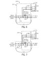
- FIG. 6 is a schematic representation of communicative features of an adaptable device in accordance with present techniques, wherein an activation mechanism of the adaptable device is disposed within a functional module of the adaptable device.
- FIG. 7 is a schematic representation of communicative features of an adaptable device in accordance with present techniques, wherein an activation mechanism of the adaptable device is disposed within a base of the adaptable device.
- FIG. 8 is a schematic representation of communicative features of an adaptable device in accordance with present techniques, wherein an activation mechanism of the adaptable includes a bridging member.
- FIG. 9 is a schematic representation of communicative features of an adaptable device in accordance with present techniques, wherein an activation mechanism of the adaptable includes a breakaway circuit.
- FIG. 10 is a process flow diagram of a method of manufacturing an adaptable automation control component in accordance with present techniques.
- FIG. 1 is a diagrammatical representation of an exemplary control and monitoring system or automation controller system adapted to interface with networked components and configuration equipment in accordance with embodiments of the present techniques.
- the control and monitoring system of FIG. 1 includes components that have adaptable functionality in accordance with present techniques.
- certain devices or modules of the control and monitoring system are capable of performing as an I/O device or as a power distribution device.
- activation or deactivation of a selection mechanism on such adaptable devices enables different functionalities.
- a selection mechanism e.g., a switch
- an adaptable device may default or be adjusted such that the adaptable device performs as an I/O device.
- the adaptable device may be configured to receive inputs into and provide outputs from the associated automation control system.
- the selection mechanism may default or be adjusted such that the adaptable device performs as a power distributor. That is, the adaptable device may be configured to disconnect or block access to bus power from upstream components of the automation control system, receive power from an external voltage or power source (e.g., an electrical grid or battery), and provide power to downstream components of the automation control system.
- an external voltage or power source e.g., an electrical grid or battery
- control and monitoring system 10 is generally indicated by reference numeral 10.
- the control and monitoring system 10 is illustrated as including a human machine interface (HMI) 12 and a control/monitoring device or automation controller 14 adapted to interface with components of a process 16.
- HMI human machine interface
- control/monitoring device or automation controller 14 adapted to interface with components of a process 16.
- an interface in accordance with embodiments of the present techniques may be facilitated by the use of certain network strategies.
- an industry standard network may be employed, such as DeviceNet, to enable data transfer.
- Such networks permit the exchange of data in accordance with a predefined protocol, and may provide power for operation of networked elements.
- the process 16 may take many forms and include devices for accomplishing many different and varied purposes.
- the process 16 may comprise a compressor station, an oil refinery, a batch operation for making food items, a mechanized assembly line, and so forth.
- the process 16 may comprise a variety of operational components, such as electric motors, valves, actuators, temperature elements, pressure sensors, or a myriad of manufacturing, processing, material handling and other applications.
- the process 16 may comprise control and monitoring equipment for regulating process variables through automation and/or observation.
- the illustrated process 16 comprises sensors 18 and actuators 20.
- the sensors 18 may comprise any number of devices adapted to provide information regarding process conditions.
- the actuators 20 may include any number of devices adapted to perform a mechanical action in response to a signal from a controller (e.g., the automation controller 14).
- the sensors 18 and actuators 20 may be utilized to operate process equipment. Indeed, they may be utilized within process loops that are monitored and controlled by the control/monitoring device 14 and/or the HMI 12. Such a process loop may be activated based on process inputs (e.g., input from a sensor 18) or direct operator input received through the HMI 12.
- the sensors 18 and actuators 20 are in communication with the control/monitoring device 14. Further, the sensors 18 and actuators 20 may be assigned a particular address in the control/monitoring device 14 and receive power from the control/monitoring device 14 or attached modules.
- the control and monitoring system 10 includes one or more adaptable automation control components or adaptable devices 22 that are capable of functioning in different modes in accordance with present techniques. These adaptable devices 22 can function as input/output (I/O) devices when in a first mode, and as power distribution devices when in a second mode. In the illustrated embodiment, several of the adaptable devices 22 are configured to transfer input and output signals between the control/monitoring device 14 and the controlled process 16. The adaptable devices 22 configured for functioning in this manner are indicated as input/output (I/O) devices 24. As illustrated, the sensors 18 and actuators 20 may communicate with the control/monitoring device 14 via one or more of the I/O devices 24 coupled to the control/monitoring device 14.
- I/O input/output
- one or more of the adaptable devices 22 may be configured to perform a power distribution function.
- power distribution device 26 represents one of the adaptable devices 22 that has been converted for functioning in such a mode. More particularly, the power distribution device 26 functions to receive power (e.g., 24V) from an external source 28 (e.g., an electrical grid or battery), and supply bus power to the other adaptable devices 22 (i.e., I/O devices 24). Power for the sensors 18 and actuators 20 (i.e., sensor actuator (SA) power) may also be provided by the power distribution device 26.
- SA sensor actuator
- the adaptable devices 22 may be added or removed from the control and monitoring system 10 via expansion slots, bays or other suitable mechanisms.
- additional adaptable devices 22 configured as I/O devices may be included to add functionality to the control/monitoring device 14, or to accommodate additional process features (e.g., to communicate with new sensors 18 or actuators 20 added to control the process 16).
- the I/O devices 24 serve as an electrical interface to the control/monitoring device 14 and may be located proximate or remote from the control/monitoring device 14, including remote network interfaces to associated systems.
- additional adaptable devices 22 configured as power distribution devices may be added to provide supplementary power when the power capabilities of one or more existing power distribution devices is exceeded. For example, an additional power distribution device may be added to accommodate the power requirements of additional I/O devices.
- the I/O devices 24 are adaptable devices 22 that have been configured to function in a particular mode of operation. This configuration may be initiated by performing one or more reversible or irreversible operations.
- one of the adaptable devices 22 may default to functioning as an I/O device, and activation of a selection mechanism on the adaptable device 22 may trigger configuration of the adaptable device as a power distribution device.
- the selection mechanism e.g., a switch
- the adaptable device 22 may function as an I/O device
- the selection mechanism is in a non-default position (e.g., the switch is open)
- the adaptable device 22 may function as a power distribution device.
- the I/O devices 24 may include an activated or deactivated selection mechanism. Further, the I/O devices 24 may include input modules that receive signals from input devices such as photo-sensors and proximity switches, output modules that use output signals to energize relays or to start motors, and bidirectional I/O modules, such as motion control modules which can direct motion devices and receive position or speed feedback. In some embodiments, the I/O devices 24 may convert between AC and DC analog signals used by devices on a controlled machine or process and +5-volt DC logic signals used by the control/monitoring device 14. Additionally, some of the I/O devices 24 may function to provide digital signals to digital I/O devices and receive digital signals from digital I/O devices. Further, in some embodiments, the I/O devices 24 that are used to control machine devices or process control devices may include local micro-computing capability on a functional module of each of the I/O devices 24.
- the I/O devices 24 in FIG. 1 receive power from the power distribution device 26, which is an adaptable device 22 modified to provide power distribution functionality.
- Adaptable devices such as the illustrated adaptable devices 22, may be converted and employed as power distribution devices (e.g., the power distribution device 26) as needed or desired.
- an adaptable device can be configured to function as the supplemental power distribution device and installed.
- supplemental I/O devices 30 may be added to the control and monitoring system 10 to accommodate additional sensors 18 and actuators 20.
- an additional power distribution device 32 may be added between the last I/O device 24 and the next supplemental I/O device 30 to be added. More specifically, in accordance with present embodiments, an adaptable device 22 may be converted or configured to function in a power distribution mode and then added to the control and monitoring system 10 as the power distribution device 32.
- the supplemental I/O devices 30 may also be adaptable devices 22 that are configured to provide the functionality of an I/O device.
- the additional power distribution device 32 will disconnect bus power between the I/O modules 24, 30 that are adjacent to the supplemental or additional power distribution device 32. Indeed, the additional power distribution device 32 may have been activated to discontinue a device power bus within the power distribution device 32. Thus, the additional power distribution device 32 breaks the bus power connection with system components arranged to the left (e.g., upstream) of the newly added power distribution module 26, and allows connection of another source voltage 34 for providing power to devices attached on the right (e.g., downstream) of the added power distribution module 32.
- components that are electrically upstream of a particular adaptable device 22 are components that are on a left side of the adaptable device 22 when viewing the adaptable device 22 from the front, and components that are electrically downstream of the adaptable device 22 are components that are on a right side of the adaptable device 22 when viewing the adaptable device 22 from the front.
- the upstream and downstream electrical coupling aspects may be configured differently.
- Present embodiments facilitate efficient configuration of control and monitoring systems (e.g., control and monitoring system 10) by providing adaptable devices (e.g., adaptable devices 22) that can function as either I/O devices (e.g., I/O devices 24, 30) or as power distribution devices (e.g., power distribution devices 26, 32).
- adaptable devices e.g., adaptable devices 22
- I/O devices e.g., I/O devices 24, 30
- power distribution devices e.g., power distribution devices 26, 32.
- present embodiments provide customers and technicians with the ability to assemble and maintain certain portions of a control and monitoring system by simply acquiring a number of the same type of module or device.
- the adaptable devices 22 can function as either I/O devices or power distribution devices, a single type of device (e.g., adaptable device 22) can be acquired for system configuration and inventoried for maintenance purposes without requiring the determination of a specific number of power distribution devices and I/O devices to include in a system or store as backup. This will improve system assembly and maintenance logistics because customers and technicians will be able to order and maintain an inventory of the same system components that can function as replacements for two different functional components of a control system.
- the adaptable devices 22 are coupled directly to the control/monitoring device 14.
- the adaptable devices 22 may be located in close proximity to aspects of the control and monitoring system 10, and away from the control/monitoring device 14.
- data may be communicated with remote modules over a common communication link, or network, wherein modules on the network communicate via a standard communications protocol.
- Ethernet e.g., IEEE802.3, TCP/IP, UDP, EtherNet/IP, and so forth
- ControlNet e.g., ControlNet
- DeviceNet e.g., DeviceNet or other network protocols
- Fraundation Fieldbus (H1 and Fast Ethernet) Modbus TCP, Profibus and also communicate to higher level computing systems.
- FIG. 2 is a front view of a plurality of adaptable devices 22 communicatively or electrically coupled to an I/O adapter 40 in accordance with embodiments of the present techniques.
- the I/O adapter 40 and the plurality of adaptable devices 22 are mounted to a bus bar or system bus (e.g., a DIN rail) 42, which is an industry standard support rail for mounting control equipment in racks and cabinets.
- the plurality of adaptable devices 22 are electrically or communicatively coupled in series along the bus bar 42 such that field power and system information and power may be communicated between the adaptable devices 22, and back through the I/O adapter 40 to the control/monitoring device 14 via one or more communication ports 44.
- the I/O adapter 40 is configured to enable conversion between the communications protocols of the adaptable devices 22 and the control/monitoring device 14.
- the I/O adapter may function as a data translator between the adaptable devices 22 and the control/monitoring device 14.
- the I/O adapter 40 may receive data from certain of the adaptable devices 22 that are configured to function as I/O devices, translate the data from a first protocol to a second protocol, and communicate the translated data to the control/monitoring device 14 via the one or more communication ports 44 communicatively coupled with the control/monitoring device 14.
- the I/O adapter 40 also receives a source voltage 46 and provides power to a subset of the illustrated adaptable devices 22. Indeed, a first set 48 of five of the adaptable devices 22 to the right of the I/O adapter 40 includes adaptable devices 22 (indicated as the I/O devices 24) that are configured to provide I/O functionality. These I/O devices 24 receive sufficient power from the I/O adapter 40. However, the I/O adapter 40 may only be equipped to provide five I/O devices 24 with sufficient power. Accordingly, the sixth adaptable device 22 to the right of the I/O adapter 40 has been converted to provide power distribution functionality, and is referred to as the power distribution device 26. The power distribution device 26 receives a source voltage 52, provides power to a second set 54 of four I/O devices 24 that are downstream of the power distribution device 26, and disconnects device bus power between the first set 48 and second set 54 of I/O devices 24.
- the power distribution device 26 has the same general appearance as the I/O devices 24. This is because, like the I/O devices 24, the power distribution device 26 is essentially an adaptable device 22 (which may have a default function as an I/O device or as a power distribution device). Indeed, the power distribution device 26 may have been converted from an I/O device 24, or vice versa. In some embodiments, as will be discussed below, certain visible aspects of the adaptable devices 22 may be changed when functionality is established to facilitate distinguishing I/O devices from power distribution devices.
- converting an adaptable device 22 from a default functionality as an I/O device 24 to a power distribution device 26 may include removing a component (e.g., a tab) that provides a clear visible distinction or activating one or more light emitting diodes that indicate the mode of operation of the adaptable device 22.
- a component e.g., a tab
- FIG. 3 is an exploded perspective view of an exemplary adaptable device 22 in accordance with embodiments of the present techniques.
- the adaptable device 22 includes a base 60, a terminal block 62, and a functional module 64.
- the base 60 is configured to physically and communicatively connect the adaptable device 22 to adjacent devices and the system bus or bus bar 42.
- the terminal block 62 (which, in certain embodiments, may be removable from the base 60) is configured for electrically connecting the adaptable device 22 to field devices (e.g., sensors or actuators) or a power source (e.g., power source 28), depending on the embodiment and the mode of operation of the adaptable device 22.
- field devices e.g., sensors or actuators
- a power source e.g., power source 28
- the functional module 64 which includes communication and control circuitry (e.g., I/O communication circuitry, control circuitry, power distribution circuitry, and/or logic), is configured to provide a selectable functionality.
- communication and control circuitry e.g., I/O communication circuitry, control circuitry, power distribution circuitry, and/or logic
- the functional module 64 of the adaptable device 22 is capable of receiving input signals from field devices via the terminal block 62, delivering output signals to the field devices via the terminal block 62, performing general and/or specific local functionality on the inputs and/or outputs, communicating the inputs and/or outputs to the control/monitoring device 14 and/or the other I/O devices 24, and so forth.
- the module 64 and/or other components of the adaptable device 22 may coordinate to perform a power distribution functionality by receiving power from a source via the terminal block 62, disconnecting from upstream bus power via a switch or the like in the base 60, terminal block 62, and/or functional module 64, and providing bus power to downstream devices via the base 60, terminal block 62, and/or functional module 64.
- the terminal block 62 is a removable terminal block that may be physically connected and electrically coupled to the base 60 during assembly of the adaptable device 22, and physically disconnected and electrically decoupled during disassembly (e.g., for servicing) of the adaptable device 22.
- the removable or detachable nature of the illustrated terminal block 62 enables replacement of the base 60 or the functional module 64 without the need for re-wiring.
- the terminal block 62 may be directly integrated with the base 60. Such integrated embodiments may be desirable, for example, in process automation control applications for which the specific arrangement of electrical connections may be somewhat complex or compact, and the ability to maintain these electrical connections or a correspondence between components during servicing is of greater importance.
- the terminal block 62 includes eight terminals 66 (i.e., channels) for connecting field device wiring or power source wiring.
- the terminals 66 may each be associated with a particular input to or output from a field device.
- two or more of the eight terminals 66 may function as a coupling to a voltage source (e.g., the external source 28).
- the terminal block 62 includes dedicated terminals 68 for use as a coupling to a voltage source when the adaptable device 22 is functioning in a power distribution configuration.
- activating the adaptable device 22 with a power distribution functionality includes exposing (e.g., by removing a tab or key) these dedicated terminals 68, which provides a visual indication of the functionality of the adaptable device 22.
- each terminal 66 includes a terminal opening 70 into which a field wire (i.e., wiring electrically connected to a field device) may be inserted, or a power source wire connected to a power source may be inserted.
- each terminal 66 includes an attachment activator (e.g., a terminal screw) 72, which when activated (e.g., tightened) causes a clamp or other electrical wiring connection mechanism within the terminal block 62 to tighten around an end of a field wire or power source wire that has been inserted into the associated terminal opening 72.
- the dedicated terminals 68 may include terminal openings 70 and attachment activators 72.
- the dedicated terminals 68 may only become active when an activation mechanism 74 (e.g., a switch or circuit bridge) of the adaptable device 22 is activated or deactivated (e.g., removed, turned, or toggled).
- the activation mechanism 74 includes a rotatable switch disposed on the base 60.
- the activation mechanism 74 may include different features and may be disposed on different components of the adaptable device 22.
- the illustrated activation mechanism 74 is configured to complete or break contact with circuitry of the adaptable device 22 such that the adaptable device functions as either an I/O device or a power distribution device.
- internal circuitry may disengage from or engage with a device power bus such that power from any upstream devices will or will not be received and/or such that certain power input terminals become active or inactive.
- the device power bus may be continued such that power is allowed to flow through the adaptable device 22, while when the activation mechanism 74 disengages from the device power bus, the device power bus may be discontinued such that power flow is broken.
- the activation mechanism 74 may be utilized to break or continue SA power.
- each of the terminals 66 terminates at the bottom of the terminal block 62 with a terminal block connector 76, which may be inserted into terminal block connector openings 80 in the top of a terminal block bay 82 of the base 60 to physically and communicatively connect the terminal block 62 with the base 60.
- each of the terminal block connectors 76 include two opposing electrical prongs 84 that slide around and electrically connect with a single electrical prong (not shown) in the respective terminal block connector opening 80 of the terminal block bay 82 of the base 60.
- other types of terminal block connectors 76 may be used to electrically connect with mating electrical connectors in the respective terminal block connector opening 80 of the terminal block bay 82 of the base 60.
- the functional module 64 may also be physically and communicatively connected to the base 60 by inserting the functional module 64 into a mating slot 90 in a module bay 92 of the base 60.
- the module 64 becomes electrically or communicatively coupled to the terminals 70 of the terminal block 62 via internal circuitry within the base 60 that electrically connects the electrical prongs (or other suitable electrical connectors) in the terminal block connector openings 80 to respective electrical outlets 94 in the top of the module bay 92 of the base 60.
- the electrical outlets 94 for each channel are in turn electrically coupled to the functional module 64 via respective electrical connectors (not shown) that, in certain embodiments, extend from the bottom of the functional module 64.
- the terminal block 62, the base 60, and the functional module 64 are all electrically and communicatively coupled together. Accordingly, when the adaptable device 22 is configured as an I/O device 24, signals to and from a field device to which the I/O device 24 is connected can be shared between the terminal block 62, the base 62, and the functional module 64, which is acting as an I/O module. Likewise, when the adaptable device is configured as a power distribution device 26, power from a voltage source can be shared among and transmitted by the terminal block 62, the base 62, and/or the functional module 64.
- adjacent adaptable devices 22 may be physically attached to each other via one or more connection features (e.g., slots) 96 of the base 60 on one of the sides (e.g., the left side of the illustrated embodiment) of the adaptable device 22 near the bottom of the base 60, and corresponding mating connection features such as protrusions (not shown) on the opposite side (e.g., the right side of the illustrated embodiment) of the base 60 of the adaptable device 22 near the bottom of the base 60.
- connection features of the adaptable device 22 may slide into mating connection features of an adjacent adaptable device 22, thereby physically attaching the adjacent adaptable devices 22, whether the adaptable devices 22 are in an I/O mode of operation or a power distribution mode of operation.
- system electrical contacts 98 on the base 60 on one of the sides align with and are electrically coupled to mating electrical contacts (not shown) on the base 60 on the opposite side (e.g., the right side of the illustrated embodiment) of an adjacent adaptable device 22.
- field electrical contacts 100 on the base 60 on one of the sides align with and are electrically coupled to mating electrical contacts (not shown) on the base 50 on the opposite side (e.g., the right side of the illustrated embodiment) of an adjacent adaptable device 22.
- the adaptable device 22 includes five system electrical contacts 98 and two field electrical contacts 100.
- system power may be electrically communicated between electrically connected adaptable devices 22 via two of the system electrical contacts 98, while the three other system electrical contacts 98 are used for transmission of data (e.g., relating to signals transmitted to and from the field devices to which the adaptable devices 22 may be electrically connected) between the electrically connected adaptable devices 22 and other system components (e.g., the I/O adapter 24 or the control/monitoring device 14).
- the two field electrical contacts 100 may be used to electrically communicate power to field devices to which the adaptable devices 22 may be electrically connected.
- the specific number of system electrical contacts 98 and field electrical contacts 100 may vary between implementations depending on the requirements for power and data transmission of the adaptable devices 22. Electrical contacts such as the field electrical contacts 100 or the system electrical contacts 98 may include extensions from the device power bus, which is essentially an integrated power bus in accordance with present embodiments.
- the functional module 64 may include a status display 102 on the top face of the functional module 64 for displaying operating status information of the adaptable device 22.
- the status display 102 may, for example, include status light emitting diodes (LEDs) corresponding to each of the terminals 66, 68 of the terminal block 62.
- the status display 102 may include certain features that provide an indication of whether the adaptable device 22 is functioning as an I/O device or a power distribution device. For example, when an activation mechanism is triggered and/or a power supply is coupled to the dedicated terminals 68, an LED or group of LEDs may be activated to provide notice that the adaptable device 22 is functioning as a power distribution device.
- a latch 104 or other fastening device extending from the terminal block 62 may further attach the terminal block 62 to the functional module 64, thereby providing additional structural support and stabilizing the electrical connections between the terminal block 62, the functional module 64, and the base 60.
- this latch 104 may also include certain electrically functional or communicative aspects. For example, engaging the latch 104 with the functional module 64 may complete or break a circuit and activate some operational feature of the adaptable device. Indeed, in some embodiments, aspects of the latch 104 may incorporate the activation mechanism 74. In some embodiments, the latch 104 extends from the base 60 or the functional module 64.
- FIG. 4 is a schematic representation of communicative features of an adaptable device 200 in accordance with present techniques.
- the adaptable device 200 includes a first terminal 202 and a second terminal 204 in a terminal block (e.g., a removable terminal block), base, or functional module of the adaptable device 200.
- the terminals 202, 204 are configured to facilitate communicative coupling of the adaptable device 200 with power (e.g., 12/24V DC).
- the first terminal 202 may be configured as a common terminal and the second terminal 204 may be configured as a voltage terminal.
- the terminals 202, 204 may be dedicated terminals (e.g., terminals 68 of FIG. 3 ) that are only used when the device 200 is being utilized as a power distribution device.
- the terminals 202, 204 may be utilized for I/O functionality when the adaptable device 200 is being utilized as an I/O device. Indeed, conversion of the adaptable device 200 to one or another type of functionality may include changing an electrical configuration of the terminals 202, 204 or circuitry coupling the terminals 202, 204 to other aspects of the adaptable device 200.
- the terminals 202, 204 are dedicated power terminals and are linked to a device power bus 206 via input lines 208.
- the device power bus 206 is integral with the adaptable device 200 and can communicatively extend to other device power buses in attached devices. Power requirements of the adaptable device 200 (e.g., a functional module of the adaptable device 200) may be acquired from the device power bus 206 via module voltage lines 210.
- the adaptable device 200 also includes an activation mechanism 212 disposed along the device power bus 206 such that the activation mechanism 212 can continue or discontinue the device power bus 206.
- the activation mechanism 212 includes a double-throw switch 214 that can be activated or deactivated to change functionality of the adaptable device 200. For example, when the adaptable device 200 is acting as a power distribution device, the switch 214 can be opened to break a communicative coupling of the device power bus 206 with any upstream power distribution devices. Power to devices downstream of the adaptable device 200 may then be provided from the terminals 202, 204 via the device power bus 206.
- the switch 214 can be closed to continue the device power bus 206 such that the adaptable device 200 can receive power for its I/O functionality from an upstream power distribution device.
- power from an upstream power distribution device can be received via the device power bus 206 and utilized by components (e.g., a functional module) of the adaptable device 200 via the module voltage lines 210.
- components of the device power bus 206 may include connectors such as system electrical contacts 98 and/or field electrical contacts 100, as illustrated in FIG. 3 .
- the activation mechanism is the double-pole single throw switch 214.
- the activation mechanism 212 includes a double hermaphroditic switch 216, which is a reversible switch that can be rotated to make or break coupling of the device power bus 206 by moving contacts of the switch 216.
- the activation mechanism 212 may be disposed in one of the various components of the adaptable device 200 (e.g., the base 60, the terminal block 62, or the functional module 64, as illustrated in FIG. 3 ).
- the activation mechanism 212 is merely represented as being a component of the adaptable device 200.
- FIGS. 6 and 7 illustrated embodiments of the adaptable device 200, wherein the activation mechanism 212 is located in specific components of the adaptable device 200, which may facilitate servicing or configuration of the adaptable device 200.
- the adaptable device 200 is illustrated in FIG.
- FIG. 6 illustrates the adaptable device 200 including the base 222, the functional module 224, and the removable terminal block 226, wherein the switch 214 is a component of the base 222.
- the activation mechanism 212 of the adaptable device 200 may enable reversible activation/deactivation of modes of operation.
- the switch 214 or the switch 216 may be closed, and when the adaptable device is to be utilized as a power distribution device, the switch 214 or switch 216 may be opened.
- the switch 214 or the switch 216 if it becomes desirable to convert from one functionality to another, the switch 214 or the switch 216 can simply be reversed (i.e., opened or closed) to change the functionality of the adaptable device 200.
- different selection mechanisms may be employed.
- a selection mechanism may not only mechanically function in a different manner than the switch 214 or the switch 216, it may also function such that once it is activated the activation is essentially irreversible. In other words, while an improperly utilized mechanism could be used to complete the circuit, it would be unintended and an incorrect usage.
- FIG. 8 is schematic representation of the adaptable device 200 including a bridging member 302 that functions as the activation mechanism 212.
- the bridging member 302 may be a component of the functional module 224 and/or the base 222.
- the bridging member 302 may include circuitry 304 that communicatively couples the device power bus 206 with an upstream device (e.g., a power distribution module) when it is coupled with the adaptable device 200, and breaks the communicative coupling when it is disengaged from the adaptable device 200.
- an upstream device e.g., a power distribution module
- the bridging member 302 may essentially function as a key for converting the adaptable device 200 between modes of operation, ln addition to breaking or continuing the device power bus 206 with respect to downstream or upstream devices, the bridging member 302 may also enable other aspects of the different modes of operation of the adaptable device 200. For example, removal of the bridging member 302 may include removal of a cover over the terminals 202, 204 to facilitate access to the terminals 202, 204 and use of the adaptable device 200 as a power distribution device. Further, attachment or removal of the bridging member 302 may provide a visual indication of the mode in which the adaptable device 200 is operating.
- the bridging member 302 and corresponding mating features on the functional module 224 or base 222 may be prominently positioned and brightly colored to provide a clear indication of its attachment or lack of attachment.
- the bridging member 302 may include large text indicating that the adaptable device 200 is being activated as an I/O module, and the portion of the adaptive device 200 covered by the bridging member 302 may include large text indicating that the adaptable device 200 is being utilized as a power distribution module.
- the bridging member 302 when the bridging member 302 is coupled to the adaptable module, it clearly indicates that the adaptable device 200 is functioning as an I/O module and covers the other text.
- the text that is not covered by the bridging member 302 clearly indicates that the adaptable device 200 is functioning as a power distribution device.
- the bridging member 302 may include one or more LEDs or other indicators that can be activated upon proper engagement with the adaptable device 200.
- the activation mechanism 212 of the adaptable device 200 may include a circuit breakaway section 402 that can be removed from the adaptable device 200 to discontinue communication of the device power bus 206 with upstream devices. Removal of the circuit breakaway section 402 may be referred to as a punch out method of mode activation.
- the circuit breakaway section 402 may include a tab 404 (e.g., a portion of a plastic housing of the adaptable device 200) with integral circuitry 406 for continuing the device power bus 206 when the circuit breakaway section 402 is in place on the adaptable device 200 or discontinuing the device power bus 206 when removed.
- the circuitry breakaway section 402 may be configured such that it can be irreversibly broken off of the adaptable device 200 to change the mode of operation of the adaptable device 200 from an I/O device functionality to a power distribution functionality.
- the circuit breakaway section 402 may be a component of the functional module 224 or the base 222. Unlike reversible embodiments of the present disclosure, once the circuit breakaway section 402 is removed, it essentially cannot be functionally replaced. Thus, once the adaptable module 200 is converted to a particular mode of operation by removing the circuit breakaway section 402, it will generally remain in the mode. However, it should be noted that the component (e.g., the base 222) on which the circuit breakaway section 402 was located may simply be replaced to change the mode of operation of the adaptable device 200 back to a default mode.
- FIG. 10 is a process flow diagram of a method of manufacturing an adaptable automation control component (e.g., adaptable device 22) in accordance with present techniques.
- the process flow diagram is generally indicated by reference numeral 500 and includes various blocks that represent acts or steps in the process.
- Block 502 represents assembling a base including an attachment feature and circuitry configured to communicatively couple with a system bus. This also includes assembling a mating feature and circuitry configured to couple the base with a functional module that includes communication and control circuitry.
- Block 504 represents installing a device power bus within the base, wherein the device power bus includes electrical contacts configured to communicatively couple the adaptable automation control component with another automation control component. In other embodiments, the device power bus may be disposed within a functional module.
- Block 506 represents installing an activation mechanism including circuitry configured to continue the device power bus when the activation mechanism is engaged and to discontinue the device power bus when the activation mechanism is disengaged.
Applications Claiming Priority (1)
| Application Number | Priority Date | Filing Date | Title |
|---|---|---|---|
| US37558710P | 2010-08-20 | 2010-08-20 |
Publications (3)
| Publication Number | Publication Date |
|---|---|
| EP2421345A2 true EP2421345A2 (de) | 2012-02-22 |
| EP2421345A3 EP2421345A3 (de) | 2018-01-17 |
| EP2421345B1 EP2421345B1 (de) | 2020-10-14 |
Family
ID=44545573
Family Applications (5)
| Application Number | Title | Priority Date | Filing Date |
|---|---|---|---|
| EP11178340.3A Active EP2421344B1 (de) | 2010-08-20 | 2011-08-22 | Eingabe-/Ausgabevorrichtungen mit rekonfigurierbarer Funktion |
| EP11178347.8A Active EP2421347B1 (de) | 2010-08-20 | 2011-08-22 | Eingabe-/Ausgabemodulbussystem und -verfahren |
| EP11178345.2A Active EP2421345B1 (de) | 2010-08-20 | 2011-08-22 | Anpassbares Automationssteuerungsmodul mit integriertem Leistungsbusverteiler |
| EP11178346.0A Active EP2421346B1 (de) | 2010-08-20 | 2011-08-22 | Automatische Steuersystemkomponenten mit elektronischen Tastenfunktionen |
| EP11178344.5A Active EP2434851B1 (de) | 2010-08-20 | 2011-08-22 | Systeme und Verfahren zur Kopplung von Eingabe-/Ausgabevorrichtungen |
Family Applications Before (2)
| Application Number | Title | Priority Date | Filing Date |
|---|---|---|---|
| EP11178340.3A Active EP2421344B1 (de) | 2010-08-20 | 2011-08-22 | Eingabe-/Ausgabevorrichtungen mit rekonfigurierbarer Funktion |
| EP11178347.8A Active EP2421347B1 (de) | 2010-08-20 | 2011-08-22 | Eingabe-/Ausgabemodulbussystem und -verfahren |
Family Applications After (2)
| Application Number | Title | Priority Date | Filing Date |
|---|---|---|---|
| EP11178346.0A Active EP2421346B1 (de) | 2010-08-20 | 2011-08-22 | Automatische Steuersystemkomponenten mit elektronischen Tastenfunktionen |
| EP11178344.5A Active EP2434851B1 (de) | 2010-08-20 | 2011-08-22 | Systeme und Verfahren zur Kopplung von Eingabe-/Ausgabevorrichtungen |
Country Status (3)
| Country | Link |
|---|---|
| US (9) | US9024486B2 (de) |
| EP (5) | EP2421344B1 (de) |
| CN (6) | CN102591833B (de) |
Cited By (1)
| Publication number | Priority date | Publication date | Assignee | Title |
|---|---|---|---|---|
| CN109996416A (zh) * | 2018-01-02 | 2019-07-09 | 瞻博网络公司 | 防止在网络设备上不适当安装电源模块的装置、系统和方法 |
Families Citing this family (73)
| Publication number | Priority date | Publication date | Assignee | Title |
|---|---|---|---|---|
| US9055687B2 (en) | 2010-08-20 | 2015-06-09 | Rockwell Automation Technologies, Inc. | Input/output circuits and devices having physically corresponding status indicators |
| US9024486B2 (en) | 2010-08-20 | 2015-05-05 | Rockwell Automation Technologies, Inc. | Adaptable automation control module with integrated power bus distributor |
| US8292647B1 (en) * | 2011-06-13 | 2012-10-23 | Tyco Electronics Corporation | Socket connector |
| EP2549843B1 (de) * | 2011-07-21 | 2015-05-27 | Siemens Aktiengesellschaft | Verfahren zum Betrieb einer Ein-/Ausgabebaugruppe und Ein-/Ausgabebaugruppe |
| US9304518B2 (en) * | 2011-08-24 | 2016-04-05 | Bio-Rad Laboratories, Inc. | Modular automated chromatography system |
| US9182886B2 (en) | 2011-11-14 | 2015-11-10 | Bio-Rad Laboratories Inc. | Chromatography configuration interface |
| USD733665S1 (en) * | 2011-12-16 | 2015-07-07 | Siemens Aktiengesellschaft | Programmable logic controller (PLC) |
| US20130212310A1 (en) * | 2012-02-14 | 2013-08-15 | Red Lion Controls, Inc. | Interface for modular input/output and data acquisition systems |
| WO2013137884A1 (en) * | 2012-03-15 | 2013-09-19 | Schneider Electric Industries Sas | Device address management in an automation control system |
| US9003095B2 (en) * | 2012-03-20 | 2015-04-07 | Rockwell Automation Technologies, Inc. | Automation control component |
| EP2654317B1 (de) * | 2012-04-17 | 2014-06-18 | Siemens Aktiengesellschaft | Ein-/Ausgabebaugruppe mit Anzeigeelement |
| US10142124B2 (en) * | 2012-05-24 | 2018-11-27 | Infineon Technologies Ag | System and method to transmit data over a bus system |
| TWI525937B (zh) * | 2012-12-21 | 2016-03-11 | 緯創資通股份有限公司 | 用來保護電源線接頭之保護裝置及其相關之電源供應器與電子系統 |
| DE102013207760B4 (de) | 2013-04-29 | 2024-02-22 | Phoenix Contact Gmbh & Co. Kg | Elektrisches Interfacemodul |
| DE102013207755A1 (de) * | 2013-04-29 | 2014-10-30 | Phoenix Contact Gmbh & Co. Kg | Elektrisches Interfacemodul |
| US20150045936A1 (en) * | 2013-08-08 | 2015-02-12 | General Electric Company | System and method for modular controller assembly supporting redundant configurations |
| US9816894B2 (en) * | 2013-09-12 | 2017-11-14 | Loren Wilcox | Gas monitoring device, system and methods |
| JP5904190B2 (ja) * | 2013-10-31 | 2016-04-13 | 横河電機株式会社 | I/oモジュール |
| JP5971268B2 (ja) * | 2014-02-05 | 2016-08-17 | 横河電機株式会社 | 電子機器 |
| US9362685B2 (en) | 2014-03-21 | 2016-06-07 | Rockwell Automation Asia Pacific Business Center Pte Ltd. | Control system components with key |
| DE102014206387A1 (de) | 2014-04-03 | 2015-10-08 | Phoenix Contact Gmbh & Co. Kg | Elektrisches Interfacemodul |
| US9875207B2 (en) * | 2014-08-14 | 2018-01-23 | Honeywell International Inc. | Remote terminal unit (RTU) hardware architecture |
| US9439312B2 (en) * | 2014-09-18 | 2016-09-06 | Artesyn Embedded Computing, Inc. | Alignment mechanism for cabling to a cylinder head |
| DE102015009564A1 (de) * | 2014-12-29 | 2016-06-30 | DEHN + SÖHNE GmbH + Co. KG. | Überspannungsschutzanordnung für die Informations- und Telekommunikationstechnik |
| US9946240B2 (en) * | 2015-01-30 | 2018-04-17 | Fisher-Rosemount Systems, Inc. | Apparatus to communicatively couple three-wire field devices to controllers in a process control system |
| TWI521826B (zh) * | 2015-02-04 | 2016-02-11 | 碩天科技股份有限公司 | 具有插座辨識功能的電源設備及電源設備的插座辨識方法 |
| US10467988B2 (en) * | 2015-02-25 | 2019-11-05 | Rockwell Automation Asia Pacific Business Center Pte. Ltd. | Amalgamated alphanumeric character display system and method |
| USD792857S1 (en) * | 2015-03-23 | 2017-07-25 | Rockwell Automation Technologies, Inc. | Removable terminal block |
| US9864352B2 (en) | 2015-06-01 | 2018-01-09 | Rockwell Automation Asia Pacific Business Ctr. Pte., Ltd. | Slice I/O—field power bus breaker |
| US9583849B1 (en) * | 2015-09-16 | 2017-02-28 | Dinkle Enterprise Co., Ltd. | Connector module with multiple connection modes |
| DE102015218108B4 (de) * | 2015-09-21 | 2017-06-01 | Ellenberger & Poensgen Gmbh | Schaltgerät |
| US10474120B2 (en) * | 2016-04-06 | 2019-11-12 | Rockwell Automation Technologies, Inc. | Systems and methods for redundant monitoring of electrical property in high availability systems |
| US10420232B2 (en) * | 2016-04-21 | 2019-09-17 | Raycap, Surge Protective Devices, Ltd. | DIN rail device mount assemblies, systems and methods including locking mechanisms |
| EP3458932A4 (de) * | 2016-05-20 | 2020-04-29 | Erico International Corporation | Verteilungsblock mit integrierter überspannungsschutzvorrichtung |
| JP6702048B2 (ja) * | 2016-07-14 | 2020-05-27 | オムロン株式会社 | ソケット |
| US10324434B2 (en) * | 2016-10-12 | 2019-06-18 | Fisher-Rosemount Systems, Inc. | Method and system for commissioning process control hardware |
| US10261486B2 (en) * | 2016-10-20 | 2019-04-16 | Rockwell Automation Technologies, Inc. | On machine input/output (I/O) system with modular connections |
| CN106358406A (zh) * | 2016-11-17 | 2017-01-25 | 广州市科迅电子科技有限公司 | 一种垂直配线架及装有该垂直配线架的机柜 |
| CN106780924A (zh) * | 2017-01-23 | 2017-05-31 | 无锡东源工业自动化有限公司 | 一种智能钥匙管理箱 |
| US9966714B1 (en) | 2017-07-05 | 2018-05-08 | Rockwell Automation Asia Pacific Business Ctr. Pte., Ltd. | I/O migration adapter for control system |
| JP6976646B2 (ja) * | 2017-07-28 | 2021-12-08 | 日東工業株式会社 | 電気設備計測ユニット |
| CN107463159B (zh) * | 2017-09-15 | 2024-02-23 | 沈阳瑞德泰科电气有限公司 | 一种工业总线io模块 |
| EP3500075B1 (de) * | 2017-12-14 | 2019-11-20 | Siemens Aktiengesellschaft | Kommunikationsmodul für ein kommunikations- oder automatisierungsgerät |
| TWI662876B (zh) * | 2018-01-22 | 2019-06-11 | 緯創資通股份有限公司 | 後罩模組 |
| EP3746851A1 (de) * | 2018-01-30 | 2020-12-09 | Parker-Hannifin Corporation | Verfahren und vorrichtung zur konfiguration von mit einer feldbussteuerung verbundenen e/a-modulen |
| US10411373B1 (en) * | 2018-03-29 | 2019-09-10 | The Boeing Company | Connector for establishing an electrical connection with terminal blocks |
| DE202018103319U1 (de) * | 2018-06-13 | 2019-09-16 | Wago Verwaltungsgesellschaft Mbh | Sensoreinrichtung für eine Reihenklemmenanordnung, Reihenklemmenanordnung, Reihenklemme, Schaltschrank sowie Ausleseeinrichtung |
| EP3833511B1 (de) * | 2018-08-06 | 2023-06-07 | Techtronic Cordless GP | Systeme und verfahren zur selektiven aktivierung des betriebs einer vorrichtung |
| US10877947B2 (en) | 2018-12-11 | 2020-12-29 | SafeGraph, Inc. | Deduplication of metadata for places |
| JP6962309B2 (ja) * | 2018-12-14 | 2021-11-05 | オムロン株式会社 | 端子台および端子台セット |
| DE102018133646A1 (de) * | 2018-12-28 | 2020-07-02 | Beckhoff Automation Gmbh | Basismodul und Funktionsmodul für ein Schaltschranksystem |
| USD900040S1 (en) * | 2019-01-31 | 2020-10-27 | Honeywell International Inc. | Module for field termination assembly |
| DE202019101037U1 (de) * | 2019-02-22 | 2020-05-25 | WAGO Verwaltungsgesellschaft mit beschränkter Haftung | Reihenklemme zum Festlegen einer Reihenklemmanordnung auf einer Tragschiene |
| US10559904B1 (en) * | 2019-03-19 | 2020-02-11 | Cisco Technology, Inc. | Link module for a scalable multiprocessor system |
| US11169505B2 (en) * | 2019-03-20 | 2021-11-09 | Rockwell Automation Technologies, Inc. | Constant input resistance for redundant input modules employed in high availability systems |
| US10739745B1 (en) | 2019-03-27 | 2020-08-11 | Rockwell Automation Technologies, Inc. | Modular backplane for an industrial controller |
| DE102019110884A1 (de) * | 2019-04-26 | 2020-10-29 | Beckhoff Automation Gmbh | Verfahren zur Änderung einer Steuerungssoftware eines Automatisierungssystems |
| CN110285848B (zh) * | 2019-07-11 | 2024-02-20 | 北京市水科学技术研究院 | 工程安全监测集线装置及工程安全监测人工测读系统 |
| DE102019122824A1 (de) * | 2019-08-26 | 2021-03-04 | Phoenix Contact Gmbh & Co. | Basiselement für eine wenigstens zweiteilige Überspannungsschutzvorrichtung und entsprechende Überspannungsschutzvorrichtung |
| EP3832409A1 (de) * | 2019-12-04 | 2021-06-09 | Helvar Oy Ab | Modulares steuergerät eines gebäudeautomatisierungssystems |
| EP4111267A4 (de) * | 2020-02-24 | 2024-04-10 | Selec Controls Private Ltd | Modulare und konfigurierbare elektrische gerätegruppe |
| US11183788B2 (en) * | 2020-04-01 | 2021-11-23 | Honeywell International Inc. | Electrical connector for a controller |
| US11899696B2 (en) * | 2020-10-06 | 2024-02-13 | SafeGraph, Inc. | Systems and methods for generating multi-part place identifiers |
| US11762914B2 (en) | 2020-10-06 | 2023-09-19 | SafeGraph, Inc. | Systems and methods for matching multi-part place identifiers |
| CN112433776B (zh) * | 2020-10-16 | 2022-06-28 | 广东电力信息科技有限公司 | 电网业务处理系统 |
| WO2022096043A2 (en) * | 2020-11-07 | 2022-05-12 | Futismo | Modular electronics |
| US11758661B2 (en) | 2021-02-19 | 2023-09-12 | Rockwell Automation Technologies, Inc. | Locking input/output module |
| US20230318875A1 (en) * | 2021-02-23 | 2023-10-05 | Phoenix Contact Development and Manufacturing, Inc. | APL Field Switch with Automatic Protocol Detection |
| US20220311161A1 (en) | 2021-03-26 | 2022-09-29 | Rockwell Automation Technologies, Inc. | Electrical component coupling/decoupling sensor arrangement |
| CN113612039B (zh) * | 2021-07-21 | 2023-06-30 | 恩尼特克电子科技(深圳)有限公司 | 螺旋弹簧式锁线端子台 |
| RU209503U1 (ru) * | 2021-11-09 | 2022-03-16 | Общество с ограниченной ответственностью "Эйдос-Робототехника" | Устройство ввода/вывода сигналов RCS IO |
| CN114883824B (zh) * | 2022-07-11 | 2022-10-21 | 宁波速普电子有限公司 | 接线端子座 |
| KR102600647B1 (ko) * | 2022-10-26 | 2023-11-09 | 이기석 | 커넥터후드의 락분리가 용이한 커넥터 |
Family Cites Families (86)
| Publication number | Priority date | Publication date | Assignee | Title |
|---|---|---|---|---|
| US741052A (en) * | 1902-01-04 | 1903-10-13 | Minna Legare Mahon | Automatic coupling for electrical conductors. |
| US1328562A (en) * | 1918-08-15 | 1920-01-20 | Connecticut Telephone & Elec | Electric switch |
| US3786392A (en) * | 1972-09-20 | 1974-01-15 | Daniel J Mc | Automatic retractable ground electrical connector |
| FR2223937B1 (de) * | 1973-03-29 | 1978-03-24 | Telemecanique Electrique | |
| US3823367A (en) | 1973-09-04 | 1974-07-09 | Mallory & Co Inc P R | Battery package with end of life condition indicator |
| US4206332A (en) * | 1977-05-09 | 1980-06-03 | Tektronix, Inc. | Coaxial switch |
| US4711510A (en) * | 1986-05-15 | 1987-12-08 | Orlando Jr Alfred J | Electrical connector for tractor-trailer rig |
| US4820182A (en) * | 1987-12-18 | 1989-04-11 | Molex Incorporated | Hermaphroditic L. I. F. mating electrical contacts |
| US5098311A (en) * | 1989-06-12 | 1992-03-24 | Ohio Associated Enterprises, Inc. | Hermaphroditic interconnect system |
| US5035639A (en) * | 1990-03-20 | 1991-07-30 | Amp Incorporated | Hermaphroditic electrical connector |
| US5483229A (en) * | 1993-02-18 | 1996-01-09 | Yokogawa Electric Corporation | Input-output unit |
| US5366609A (en) * | 1993-06-08 | 1994-11-22 | Boehringer Mannheim Corporation | Biosensing meter with pluggable memory key |
| US5472347A (en) | 1993-09-17 | 1995-12-05 | Allen-Bradley Company, Inc. | System for interconnecting I/O modules for data communications over a common backplane |
| DE4402002B4 (de) * | 1994-01-18 | 2005-10-27 | Wago Verwaltungsgesellschaft Mbh | E/A-Module/ für einen Datenbus |
| DE4402001B4 (de) * | 1994-01-18 | 2007-02-22 | Wago Verwaltungsgesellschaft Mbh | E/A-Modul für einen Datenbus |
| US5413501A (en) * | 1994-01-31 | 1995-05-09 | Munn; Roger D. | Electrical outlet |
| DE4438806C1 (de) * | 1994-10-31 | 1996-03-21 | Weidmueller Interface | Modulare Steuerungsanlage mit Busleiter |
| US5493194A (en) * | 1995-02-14 | 1996-02-20 | Allen-Bradley Company, Inc. | Control signal and power bus connector arrangement for a multi-axis motor control |
| US6008985A (en) * | 1995-11-20 | 1999-12-28 | The Foxboro Company | Industrial field controlling device with controller and expansion modules |
| US6311229B1 (en) * | 1996-06-04 | 2001-10-30 | Elsag International N.V. | Color coding identification system for a block I/O system |
| US5775955A (en) * | 1996-09-17 | 1998-07-07 | Graube; Maris | Modular fieldbus terminal block |
| US5897399A (en) * | 1997-01-16 | 1999-04-27 | Hewlett-Packard Company | Versatile input/output control and power distribution block for use with automated tooling |
| US5899753A (en) * | 1997-04-03 | 1999-05-04 | Raytheon Company | Spring-loaded ball contact connector |
| DE19807710C2 (de) * | 1998-02-24 | 2002-07-18 | Siemens Ag | Modulares Automatisierungsgerät und Baugruppe eines modularen Automatisierungsgerätes |
| US6226762B1 (en) * | 1998-04-20 | 2001-05-01 | National Instruments Corporation | System and method for providing delayed start-up of an activity monitor in a distributed I/O system |
| US6175932B1 (en) | 1998-04-20 | 2001-01-16 | National Instruments Corporation | System and method for providing state capture and restoration to an I/O system |
| US6331935B1 (en) * | 1998-09-29 | 2001-12-18 | Rockwell Automation Technologies, Inc. | Controller assembly having a base unit with a dockable processor unit |
| US6172875B1 (en) * | 1998-11-17 | 2001-01-09 | Rockwell Technologies, Llc | Programmable logic controller module assembly and locking system |
| US6283786B1 (en) * | 1998-12-18 | 2001-09-04 | Molex Incorporated | Electrical connector assembly with light transmission means |
| US6288911B1 (en) * | 1999-02-18 | 2001-09-11 | Intel Corporation | Hot plug solution and adjustable retention bracket |
| US6411505B1 (en) * | 1999-11-12 | 2002-06-25 | Apple Computer, Inc. | Computer housing for a portable computer |
| US20010034165A1 (en) * | 2000-03-10 | 2001-10-25 | Landis John M. | Terminal block connector |
| US6425770B1 (en) * | 2000-04-14 | 2002-07-30 | Rockwell Automation Technologies, Inc. | Input/output device having removable module |
| JP2002008778A (ja) * | 2000-04-20 | 2002-01-11 | Kel Corp | カードコネクタ |
| FR2810833B1 (fr) * | 2000-06-27 | 2002-09-20 | Thomson Multimedia Sa | Appareil multimedia de reception d4emission audiovisuelle |
| GB0019449D0 (en) * | 2000-08-09 | 2000-09-27 | Connell Michelle C O | Electric socket/plug cover |
| US6661334B1 (en) * | 2000-09-26 | 2003-12-09 | Hewlett-Packard Development Company, L.P. | Methods and apparatus for verifying the installation of components in a system |
| ATE241162T1 (de) * | 2000-11-30 | 2003-06-15 | Siemens Building Tech Ag | Anordnung zur überwachung, steuerung und regelung einer betriebstechnischen anlage eines gebäudes |
| US7032051B2 (en) * | 2000-12-11 | 2006-04-18 | Linear Technology Corp. | Methods and circuitry for interconnecting data and clock busses of live backplane circuitry and input/output card circuitry, and methods and circuitry for isolating capacitanes of a live backplane from the capacitanes of at least one input/output card |
| US20020108009A1 (en) * | 2000-12-29 | 2002-08-08 | Michele Borgatti | Electronic system having modular expansion function facilities |
| US6629852B2 (en) * | 2001-03-15 | 2003-10-07 | Omron Corporation | Relay socket |
| US8028099B2 (en) * | 2001-04-20 | 2011-09-27 | Rockwell Automation Technologies, Inc. | Industrial control system with web enabled I/O modules |
| US7370239B2 (en) * | 2001-05-31 | 2008-05-06 | Fisher-Rosemount Systems, Inc. | Input/output device with configuration, fault isolation and redundant fault assist functionality |
| US6816919B2 (en) | 2001-07-16 | 2004-11-09 | Ge Fanuc Automation North America, Inc. | Method and system for configuring input/output points |
| US7748620B2 (en) * | 2002-01-11 | 2010-07-06 | Hand Held Products, Inc. | Transaction terminal including imaging module |
| JP3861121B2 (ja) * | 2002-01-18 | 2006-12-20 | 日本圧着端子製造株式会社 | カードコネクタ |
| TW591509B (en) * | 2003-01-28 | 2004-06-11 | Via Tech Inc | USB control circuit and operation method applied in computer-to-computer transmission |
| JP2005031812A (ja) * | 2003-07-08 | 2005-02-03 | Toshiba Corp | 画像形成装置およびその制御方法 |
| US7097495B2 (en) | 2003-07-14 | 2006-08-29 | Tribotek, Inc. | System and methods for connecting electrical components |
| DE102004002737A1 (de) * | 2004-01-20 | 2005-08-11 | Wago Verwaltungsgesellschaft Mbh | Lösemechanismus |
| DE102004015227A1 (de) * | 2004-03-24 | 2005-10-27 | Siemens Ag | Elektrisches Feldgerät |
| US7576630B2 (en) * | 2004-09-13 | 2009-08-18 | Cooper Technologies Company | Fusible switching disconnect modules and devices |
| US7855873B2 (en) * | 2004-09-13 | 2010-12-21 | Cooper Technologies Company | Panelboard for fusible switching disconnect devices |
| US7442068B2 (en) * | 2004-09-24 | 2008-10-28 | Siemens Schweiz Ag | Electrical device having a base and an electrical module |
| DE502004008417D1 (de) * | 2004-09-24 | 2008-12-18 | Siemens Ag | Adressierung eines elektrischen Moduls mittels Verriegelung |
| US20060086530A1 (en) * | 2004-10-21 | 2006-04-27 | Robert Knabel | Wiring connector organizer |
| DE102004056243A1 (de) | 2004-11-22 | 2006-05-24 | Abb Patent Gmbh | Modulares Automatisierungssystem |
| US20060143473A1 (en) * | 2004-12-29 | 2006-06-29 | Kumar Mohan J | Software key implementation using system management firmware |
| US7297019B2 (en) * | 2005-03-03 | 2007-11-20 | Tyco Electronics Corporation | Pluggable screwless wire connector system |
| US8055814B2 (en) * | 2005-03-18 | 2011-11-08 | Rockwell Automation Technologies, Inc. | Universal safety I/O module |
| US20060250210A1 (en) * | 2005-05-05 | 2006-11-09 | Dowil Matthew T | Modular indicating fuse holder |
| JP4415981B2 (ja) * | 2005-09-09 | 2010-02-17 | オムロン株式会社 | プログラマブル・コントローラのリモートターミナル装置 |
| US20070073850A1 (en) * | 2005-09-29 | 2007-03-29 | Rockwell Automation Technologies, Inc. | Industrial control device configuration and discovery |
| EP1963981B1 (de) | 2005-12-20 | 2011-10-26 | Siemens Aktiengesellschaft | Backplane für eine programmierbare logische steuerung |
| US7432817B2 (en) * | 2006-03-23 | 2008-10-07 | Xerox Corporation | Module with RFID tag and associated bridge antenna |
| US7666004B2 (en) * | 2006-06-29 | 2010-02-23 | Siemens Industry, Inc. | Devices, systems, and/or methods regarding a programmable logic controller |
| US20080114902A1 (en) * | 2006-11-09 | 2008-05-15 | Keen Hun Leong | I/O module with embedded configuration software for industrial applications |
| US7508326B2 (en) * | 2006-12-21 | 2009-03-24 | Sigmatel, Inc. | Automatically disabling input/output signal processing based on the required multimedia format |
| JP2008206094A (ja) * | 2007-02-22 | 2008-09-04 | Sony Corp | クレードル |
| US8412269B1 (en) * | 2007-03-26 | 2013-04-02 | Celio Technology Corporation | Systems and methods for providing additional functionality to a device for increased usability |
| US8175099B2 (en) | 2007-05-14 | 2012-05-08 | Microsoft Corporation | Embedded system development platform |
| EP2017791A1 (de) * | 2007-07-10 | 2009-01-21 | Deutsche Post AG | Verfahren, Vorrichtung und Logistiksystem zum Befördern einer Postsendung |
| US7491096B1 (en) * | 2007-07-31 | 2009-02-17 | Phoenix Contact Development & Manufacturing Inc. | Modular terminal block |
| DE102007041406A1 (de) * | 2007-08-31 | 2009-03-12 | Phoenix Contact Gmbh & Co. Kg | Verriegelungseinrichtung für ein Gehäuse zur Aufnahme eines Einsteckmoduls |
| WO2009131985A2 (en) * | 2008-04-21 | 2009-10-29 | Inncom International Inc | Smart wall box |
| US7607929B1 (en) * | 2008-06-30 | 2009-10-27 | Tyco Electronics Corporation | Electrical connector assembly having spring loaded electrical connector |
| US9483429B2 (en) * | 2008-07-14 | 2016-11-01 | Texas Instruments Incorporated | Unified input/output controller for integrated wireless devices |
| KR20100011740A (ko) * | 2008-07-25 | 2010-02-03 | 엘지전자 주식회사 | 호스트 및 클라이언트 디바이스와 이를 이용한 클래스 변경방법 |
| US8549589B2 (en) * | 2008-11-10 | 2013-10-01 | Jeff STOLLMAN | Methods and apparatus for transacting with multiple domains based on a credential |
| CN101763112B (zh) * | 2008-12-22 | 2012-08-08 | 重庆川仪自动化股份有限公司 | 过程自动化系统i/o模块自动检测系统 |
| US8203851B2 (en) | 2009-02-09 | 2012-06-19 | Juniper Networks, Inc. | Retention-extraction device for removable cards in a chassis |
| US20110058201A1 (en) * | 2009-09-08 | 2011-03-10 | Xerox Corporation | Method and apparatus for identifying parts in an image production device |
| US8275560B2 (en) * | 2009-09-10 | 2012-09-25 | Intel Corporation | Power measurement techniques of a system-on-chip (SOC) |
| US7865629B1 (en) * | 2009-11-24 | 2011-01-04 | Microsoft Corporation | Configurable connector for system-level communication |
| US9055687B2 (en) | 2010-08-20 | 2015-06-09 | Rockwell Automation Technologies, Inc. | Input/output circuits and devices having physically corresponding status indicators |
| US9024486B2 (en) | 2010-08-20 | 2015-05-05 | Rockwell Automation Technologies, Inc. | Adaptable automation control module with integrated power bus distributor |
-
2011
- 2011-08-19 US US13/213,950 patent/US9024486B2/en active Active
- 2011-08-19 US US13/213,991 patent/US9077108B2/en active Active
- 2011-08-19 US US13/214,027 patent/US8579639B2/en active Active
- 2011-08-19 US US13/214,035 patent/US9106019B2/en active Active
- 2011-08-19 US US13/213,921 patent/US8628004B2/en active Active
- 2011-08-22 CN CN201110245463.0A patent/CN102591833B/zh active Active
- 2011-08-22 CN CN201110245441.4A patent/CN102591317B/zh active Active
- 2011-08-22 CN CN2011102454927A patent/CN102591818A/zh active Pending
- 2011-08-22 EP EP11178340.3A patent/EP2421344B1/de active Active
- 2011-08-22 EP EP11178347.8A patent/EP2421347B1/de active Active
- 2011-08-22 CN CN201110245437.8A patent/CN102594330B/zh active Active
- 2011-08-22 EP EP11178345.2A patent/EP2421345B1/de active Active
- 2011-08-22 EP EP11178346.0A patent/EP2421346B1/de active Active
- 2011-08-22 CN CN201110245444.8A patent/CN102591266B/zh active Active
- 2011-08-22 CN CN201110245477.2A patent/CN102591216B/zh active Active
- 2011-08-22 EP EP11178344.5A patent/EP2434851B1/de active Active
-
2013
- 2013-11-08 US US14/075,315 patent/US9059539B2/en active Active
-
2015
- 2015-05-04 US US14/703,625 patent/US10028404B2/en active Active
- 2015-05-19 US US14/716,697 patent/US10154603B2/en active Active
- 2015-08-07 US US14/821,488 patent/US9411614B2/en active Active
Non-Patent Citations (1)
| Title |
|---|
| None |
Cited By (2)
| Publication number | Priority date | Publication date | Assignee | Title |
|---|---|---|---|---|
| CN109996416A (zh) * | 2018-01-02 | 2019-07-09 | 瞻博网络公司 | 防止在网络设备上不适当安装电源模块的装置、系统和方法 |
| CN109996416B (zh) * | 2018-01-02 | 2021-03-09 | 瞻博网络公司 | 防止在网络设备上不适当安装电源模块的装置和方法 |
Also Published As
Similar Documents
| Publication | Publication Date | Title |
|---|---|---|
| US10028404B2 (en) | Adaptable automation control module with integrated power bus distributor | |
| US9483928B2 (en) | Input/output circuits and devices having physically corresponding status indicators | |
| EP3104237B1 (de) | Scheiben-i/o-feldenergiebusschutzschalter | |
| US9058031B2 (en) | Display module for toolless coupling with programmable controller | |
| EP2887783B1 (de) | Slice-E/A-Gehäuse mit seitlicher Belüftung | |
| US8625261B2 (en) | Interlocking system for connecting a programmable logic controller and a power supply | |
| US9003095B2 (en) | Automation control component |
Legal Events
| Date | Code | Title | Description |
|---|---|---|---|
| AK | Designated contracting states |
Kind code of ref document: A2 Designated state(s): AL AT BE BG CH CY CZ DE DK EE ES FI FR GB GR HR HU IE IS IT LI LT LU LV MC MK MT NL NO PL PT RO RS SE SI SK SM TR |
|
| AX | Request for extension of the european patent |
Extension state: BA ME |
|
| PUAI | Public reference made under article 153(3) epc to a published international application that has entered the european phase |
Free format text: ORIGINAL CODE: 0009012 |
|
| PUAL | Search report despatched |
Free format text: ORIGINAL CODE: 0009013 |
|
| AK | Designated contracting states |
Kind code of ref document: A3 Designated state(s): AL AT BE BG CH CY CZ DE DK EE ES FI FR GB GR HR HU IE IS IT LI LT LU LV MC MK MT NL NO PL PT RO RS SE SI SK SM TR |
|
| AX | Request for extension of the european patent |
Extension state: BA ME |
|
| RIC1 | Information provided on ipc code assigned before grant |
Ipc: G05B 15/02 20060101ALI20171211BHEP Ipc: H01R 13/629 20060101ALI20171211BHEP Ipc: H01R 13/62 20060101ALI20171211BHEP Ipc: H01R 13/635 20060101ALI20171211BHEP Ipc: G06F 9/445 20180101ALI20171211BHEP Ipc: G06F 13/10 20060101ALI20171211BHEP Ipc: G05B 19/05 20060101ALI20171211BHEP Ipc: H05K 7/14 20060101AFI20171211BHEP |
|
| STAA | Information on the status of an ep patent application or granted ep patent |
Free format text: STATUS: REQUEST FOR EXAMINATION WAS MADE |
|
| 17P | Request for examination filed |
Effective date: 20180605 |
|
| RBV | Designated contracting states (corrected) |
Designated state(s): AL AT BE BG CH CY CZ DE DK EE ES FI FR GB GR HR HU IE IS IT LI LT LU LV MC MK MT NL NO PL PT RO RS SE SI SK SM TR |
|
| GRAP | Despatch of communication of intention to grant a patent |
Free format text: ORIGINAL CODE: EPIDOSNIGR1 |
|
| STAA | Information on the status of an ep patent application or granted ep patent |
Free format text: STATUS: GRANT OF PATENT IS INTENDED |
|
| INTG | Intention to grant announced |
Effective date: 20200527 |
|
| GRAS | Grant fee paid |
Free format text: ORIGINAL CODE: EPIDOSNIGR3 |
|
| GRAA | (expected) grant |
Free format text: ORIGINAL CODE: 0009210 |
|
| STAA | Information on the status of an ep patent application or granted ep patent |
Free format text: STATUS: THE PATENT HAS BEEN GRANTED |
|
| AK | Designated contracting states |
Kind code of ref document: B1 Designated state(s): AL AT BE BG CH CY CZ DE DK EE ES FI FR GB GR HR HU IE IS IT LI LT LU LV MC MK MT NL NO PL PT RO RS SE SI SK SM TR |
|
| REG | Reference to a national code |
Ref country code: GB Ref legal event code: FG4D |
|
| REG | Reference to a national code |
Ref country code: AT Ref legal event code: REF Ref document number: 1324848 Country of ref document: AT Kind code of ref document: T Effective date: 20201015 Ref country code: CH Ref legal event code: EP |
|
| REG | Reference to a national code |
Ref country code: DE Ref legal event code: R096 Ref document number: 602011068911 Country of ref document: DE |
|
| REG | Reference to a national code |
Ref country code: IE Ref legal event code: FG4D |
|
| REG | Reference to a national code |
Ref country code: AT Ref legal event code: MK05 Ref document number: 1324848 Country of ref document: AT Kind code of ref document: T Effective date: 20201014 |
|
| REG | Reference to a national code |
Ref country code: NL Ref legal event code: MP Effective date: 20201014 |
|
| PG25 | Lapsed in a contracting state [announced via postgrant information from national office to epo] |
Ref country code: PT Free format text: LAPSE BECAUSE OF FAILURE TO SUBMIT A TRANSLATION OF THE DESCRIPTION OR TO PAY THE FEE WITHIN THE PRESCRIBED TIME-LIMIT Effective date: 20210215 Ref country code: NL Free format text: LAPSE BECAUSE OF FAILURE TO SUBMIT A TRANSLATION OF THE DESCRIPTION OR TO PAY THE FEE WITHIN THE PRESCRIBED TIME-LIMIT Effective date: 20201014 Ref country code: NO Free format text: LAPSE BECAUSE OF FAILURE TO SUBMIT A TRANSLATION OF THE DESCRIPTION OR TO PAY THE FEE WITHIN THE PRESCRIBED TIME-LIMIT Effective date: 20210114 Ref country code: FI Free format text: LAPSE BECAUSE OF FAILURE TO SUBMIT A TRANSLATION OF THE DESCRIPTION OR TO PAY THE FEE WITHIN THE PRESCRIBED TIME-LIMIT Effective date: 20201014 Ref country code: RS Free format text: LAPSE BECAUSE OF FAILURE TO SUBMIT A TRANSLATION OF THE DESCRIPTION OR TO PAY THE FEE WITHIN THE PRESCRIBED TIME-LIMIT Effective date: 20201014 Ref country code: GR Free format text: LAPSE BECAUSE OF FAILURE TO SUBMIT A TRANSLATION OF THE DESCRIPTION OR TO PAY THE FEE WITHIN THE PRESCRIBED TIME-LIMIT Effective date: 20210115 |
|
| REG | Reference to a national code |
Ref country code: LT Ref legal event code: MG4D |
|
| PG25 | Lapsed in a contracting state [announced via postgrant information from national office to epo] |
Ref country code: LV Free format text: LAPSE BECAUSE OF FAILURE TO SUBMIT A TRANSLATION OF THE DESCRIPTION OR TO PAY THE FEE WITHIN THE PRESCRIBED TIME-LIMIT Effective date: 20201014 Ref country code: PL Free format text: LAPSE BECAUSE OF FAILURE TO SUBMIT A TRANSLATION OF THE DESCRIPTION OR TO PAY THE FEE WITHIN THE PRESCRIBED TIME-LIMIT Effective date: 20201014 Ref country code: SE Free format text: LAPSE BECAUSE OF FAILURE TO SUBMIT A TRANSLATION OF THE DESCRIPTION OR TO PAY THE FEE WITHIN THE PRESCRIBED TIME-LIMIT Effective date: 20201014 Ref country code: IS Free format text: LAPSE BECAUSE OF FAILURE TO SUBMIT A TRANSLATION OF THE DESCRIPTION OR TO PAY THE FEE WITHIN THE PRESCRIBED TIME-LIMIT Effective date: 20210214 Ref country code: ES Free format text: LAPSE BECAUSE OF FAILURE TO SUBMIT A TRANSLATION OF THE DESCRIPTION OR TO PAY THE FEE WITHIN THE PRESCRIBED TIME-LIMIT Effective date: 20201014 Ref country code: AT Free format text: LAPSE BECAUSE OF FAILURE TO SUBMIT A TRANSLATION OF THE DESCRIPTION OR TO PAY THE FEE WITHIN THE PRESCRIBED TIME-LIMIT Effective date: 20201014 Ref country code: BG Free format text: LAPSE BECAUSE OF FAILURE TO SUBMIT A TRANSLATION OF THE DESCRIPTION OR TO PAY THE FEE WITHIN THE PRESCRIBED TIME-LIMIT Effective date: 20210114 |
|
| PG25 | Lapsed in a contracting state [announced via postgrant information from national office to epo] |
Ref country code: HR Free format text: LAPSE BECAUSE OF FAILURE TO SUBMIT A TRANSLATION OF THE DESCRIPTION OR TO PAY THE FEE WITHIN THE PRESCRIBED TIME-LIMIT Effective date: 20201014 |
|
| REG | Reference to a national code |
Ref country code: DE Ref legal event code: R097 Ref document number: 602011068911 Country of ref document: DE |
|
| PG25 | Lapsed in a contracting state [announced via postgrant information from national office to epo] |
Ref country code: SK Free format text: LAPSE BECAUSE OF FAILURE TO SUBMIT A TRANSLATION OF THE DESCRIPTION OR TO PAY THE FEE WITHIN THE PRESCRIBED TIME-LIMIT Effective date: 20201014 Ref country code: RO Free format text: LAPSE BECAUSE OF FAILURE TO SUBMIT A TRANSLATION OF THE DESCRIPTION OR TO PAY THE FEE WITHIN THE PRESCRIBED TIME-LIMIT Effective date: 20201014 Ref country code: LT Free format text: LAPSE BECAUSE OF FAILURE TO SUBMIT A TRANSLATION OF THE DESCRIPTION OR TO PAY THE FEE WITHIN THE PRESCRIBED TIME-LIMIT Effective date: 20201014 Ref country code: SM Free format text: LAPSE BECAUSE OF FAILURE TO SUBMIT A TRANSLATION OF THE DESCRIPTION OR TO PAY THE FEE WITHIN THE PRESCRIBED TIME-LIMIT Effective date: 20201014 Ref country code: CZ Free format text: LAPSE BECAUSE OF FAILURE TO SUBMIT A TRANSLATION OF THE DESCRIPTION OR TO PAY THE FEE WITHIN THE PRESCRIBED TIME-LIMIT Effective date: 20201014 Ref country code: EE Free format text: LAPSE BECAUSE OF FAILURE TO SUBMIT A TRANSLATION OF THE DESCRIPTION OR TO PAY THE FEE WITHIN THE PRESCRIBED TIME-LIMIT Effective date: 20201014 |
|
| PLBE | No opposition filed within time limit |
Free format text: ORIGINAL CODE: 0009261 |
|
| STAA | Information on the status of an ep patent application or granted ep patent |
Free format text: STATUS: NO OPPOSITION FILED WITHIN TIME LIMIT |
|
| PG25 | Lapsed in a contracting state [announced via postgrant information from national office to epo] |
Ref country code: DK Free format text: LAPSE BECAUSE OF FAILURE TO SUBMIT A TRANSLATION OF THE DESCRIPTION OR TO PAY THE FEE WITHIN THE PRESCRIBED TIME-LIMIT Effective date: 20201014 |
|
| 26N | No opposition filed |
Effective date: 20210715 |
|
| PG25 | Lapsed in a contracting state [announced via postgrant information from national office to epo] |
Ref country code: AL Free format text: LAPSE BECAUSE OF FAILURE TO SUBMIT A TRANSLATION OF THE DESCRIPTION OR TO PAY THE FEE WITHIN THE PRESCRIBED TIME-LIMIT Effective date: 20201014 Ref country code: IT Free format text: LAPSE BECAUSE OF FAILURE TO SUBMIT A TRANSLATION OF THE DESCRIPTION OR TO PAY THE FEE WITHIN THE PRESCRIBED TIME-LIMIT Effective date: 20201014 |
|
| PG25 | Lapsed in a contracting state [announced via postgrant information from national office to epo] |
Ref country code: SI Free format text: LAPSE BECAUSE OF FAILURE TO SUBMIT A TRANSLATION OF THE DESCRIPTION OR TO PAY THE FEE WITHIN THE PRESCRIBED TIME-LIMIT Effective date: 20201014 |
|
| REG | Reference to a national code |
Ref country code: CH Ref legal event code: PL |
|
| PG25 | Lapsed in a contracting state [announced via postgrant information from national office to epo] |
Ref country code: MC Free format text: LAPSE BECAUSE OF FAILURE TO SUBMIT A TRANSLATION OF THE DESCRIPTION OR TO PAY THE FEE WITHIN THE PRESCRIBED TIME-LIMIT Effective date: 20201014 |
|
| REG | Reference to a national code |
Ref country code: BE Ref legal event code: MM Effective date: 20210831 |
|
| PG25 | Lapsed in a contracting state [announced via postgrant information from national office to epo] |
Ref country code: LI Free format text: LAPSE BECAUSE OF NON-PAYMENT OF DUE FEES Effective date: 20210831 Ref country code: CH Free format text: LAPSE BECAUSE OF NON-PAYMENT OF DUE FEES Effective date: 20210831 |
|
| PG25 | Lapsed in a contracting state [announced via postgrant information from national office to epo] |
Ref country code: IS Free format text: LAPSE BECAUSE OF FAILURE TO SUBMIT A TRANSLATION OF THE DESCRIPTION OR TO PAY THE FEE WITHIN THE PRESCRIBED TIME-LIMIT Effective date: 20210214 Ref country code: LU Free format text: LAPSE BECAUSE OF NON-PAYMENT OF DUE FEES Effective date: 20210822 |
|
| PG25 | Lapsed in a contracting state [announced via postgrant information from national office to epo] |
Ref country code: IE Free format text: LAPSE BECAUSE OF NON-PAYMENT OF DUE FEES Effective date: 20210822 Ref country code: BE Free format text: LAPSE BECAUSE OF NON-PAYMENT OF DUE FEES Effective date: 20210831 |
|
| PG25 | Lapsed in a contracting state [announced via postgrant information from national office to epo] |
Ref country code: HU Free format text: LAPSE BECAUSE OF FAILURE TO SUBMIT A TRANSLATION OF THE DESCRIPTION OR TO PAY THE FEE WITHIN THE PRESCRIBED TIME-LIMIT; INVALID AB INITIO Effective date: 20110822 Ref country code: CY Free format text: LAPSE BECAUSE OF FAILURE TO SUBMIT A TRANSLATION OF THE DESCRIPTION OR TO PAY THE FEE WITHIN THE PRESCRIBED TIME-LIMIT Effective date: 20201014 |
|
| P01 | Opt-out of the competence of the unified patent court (upc) registered |
Effective date: 20230404 |
|
| PGFP | Annual fee paid to national office [announced via postgrant information from national office to epo] |
Ref country code: GB Payment date: 20230720 Year of fee payment: 13 |
|
| PGFP | Annual fee paid to national office [announced via postgrant information from national office to epo] |
Ref country code: FR Payment date: 20230720 Year of fee payment: 13 Ref country code: DE Payment date: 20230720 Year of fee payment: 13 |
|
| PG25 | Lapsed in a contracting state [announced via postgrant information from national office to epo] |
Ref country code: MK Free format text: LAPSE BECAUSE OF FAILURE TO SUBMIT A TRANSLATION OF THE DESCRIPTION OR TO PAY THE FEE WITHIN THE PRESCRIBED TIME-LIMIT Effective date: 20201014 |