EP2419613B1 - Exhaust gas treatment device - Google Patents
Exhaust gas treatment device Download PDFInfo
- Publication number
- EP2419613B1 EP2419613B1 EP10764780.2A EP10764780A EP2419613B1 EP 2419613 B1 EP2419613 B1 EP 2419613B1 EP 10764780 A EP10764780 A EP 10764780A EP 2419613 B1 EP2419613 B1 EP 2419613B1
- Authority
- EP
- European Patent Office
- Prior art keywords
- mounting mat
- fibers
- weight percent
- intumescent
- mat
- Prior art date
- Legal status (The legal status is an assumption and is not a legal conclusion. Google has not performed a legal analysis and makes no representation as to the accuracy of the status listed.)
- Not-in-force
Links
Images
Classifications
-
- B—PERFORMING OPERATIONS; TRANSPORTING
- B32—LAYERED PRODUCTS
- B32B—LAYERED PRODUCTS, i.e. PRODUCTS BUILT-UP OF STRATA OF FLAT OR NON-FLAT, e.g. CELLULAR OR HONEYCOMB, FORM
- B32B5/00—Layered products characterised by the non- homogeneity or physical structure, i.e. comprising a fibrous, filamentary, particulate or foam layer; Layered products characterised by having a layer differing constitutionally or physically in different parts
- B32B5/16—Layered products characterised by the non- homogeneity or physical structure, i.e. comprising a fibrous, filamentary, particulate or foam layer; Layered products characterised by having a layer differing constitutionally or physically in different parts characterised by features of a layer formed of particles, e.g. chips, powder or granules
-
- B—PERFORMING OPERATIONS; TRANSPORTING
- B32—LAYERED PRODUCTS
- B32B—LAYERED PRODUCTS, i.e. PRODUCTS BUILT-UP OF STRATA OF FLAT OR NON-FLAT, e.g. CELLULAR OR HONEYCOMB, FORM
- B32B17/00—Layered products essentially comprising sheet glass, or glass, slag, or like fibres
- B32B17/02—Layered products essentially comprising sheet glass, or glass, slag, or like fibres in the form of fibres or filaments
-
- F—MECHANICAL ENGINEERING; LIGHTING; HEATING; WEAPONS; BLASTING
- F01—MACHINES OR ENGINES IN GENERAL; ENGINE PLANTS IN GENERAL; STEAM ENGINES
- F01N—GAS-FLOW SILENCERS OR EXHAUST APPARATUS FOR MACHINES OR ENGINES IN GENERAL; GAS-FLOW SILENCERS OR EXHAUST APPARATUS FOR INTERNAL-COMBUSTION ENGINES
- F01N3/00—Exhaust or silencing apparatus having means for purifying, rendering innocuous, or otherwise treating exhaust
- F01N3/08—Exhaust or silencing apparatus having means for purifying, rendering innocuous, or otherwise treating exhaust for rendering innocuous
- F01N3/10—Exhaust or silencing apparatus having means for purifying, rendering innocuous, or otherwise treating exhaust for rendering innocuous by thermal or catalytic conversion of noxious components of exhaust
- F01N3/24—Exhaust or silencing apparatus having means for purifying, rendering innocuous, or otherwise treating exhaust for rendering innocuous by thermal or catalytic conversion of noxious components of exhaust characterised by constructional aspects of converting apparatus
- F01N3/28—Construction of catalytic reactors
- F01N3/2839—Arrangements for mounting catalyst support in housing, e.g. with means for compensating thermal expansion or vibration
- F01N3/2853—Arrangements for mounting catalyst support in housing, e.g. with means for compensating thermal expansion or vibration using mats or gaskets between catalyst body and housing
- F01N3/2857—Arrangements for mounting catalyst support in housing, e.g. with means for compensating thermal expansion or vibration using mats or gaskets between catalyst body and housing the mats or gaskets being at least partially made of intumescent material, e.g. unexpanded vermiculite
-
- Y—GENERAL TAGGING OF NEW TECHNOLOGICAL DEVELOPMENTS; GENERAL TAGGING OF CROSS-SECTIONAL TECHNOLOGIES SPANNING OVER SEVERAL SECTIONS OF THE IPC; TECHNICAL SUBJECTS COVERED BY FORMER USPC CROSS-REFERENCE ART COLLECTIONS [XRACs] AND DIGESTS
- Y10—TECHNICAL SUBJECTS COVERED BY FORMER USPC
- Y10T—TECHNICAL SUBJECTS COVERED BY FORMER US CLASSIFICATION
- Y10T29/00—Metal working
- Y10T29/49—Method of mechanical manufacture
- Y10T29/49826—Assembling or joining
-
- Y—GENERAL TAGGING OF NEW TECHNOLOGICAL DEVELOPMENTS; GENERAL TAGGING OF CROSS-SECTIONAL TECHNOLOGIES SPANNING OVER SEVERAL SECTIONS OF THE IPC; TECHNICAL SUBJECTS COVERED BY FORMER USPC CROSS-REFERENCE ART COLLECTIONS [XRACs] AND DIGESTS
- Y10—TECHNICAL SUBJECTS COVERED BY FORMER USPC
- Y10T—TECHNICAL SUBJECTS COVERED BY FORMER US CLASSIFICATION
- Y10T428/00—Stock material or miscellaneous articles
- Y10T428/13—Hollow or container type article [e.g., tube, vase, etc.]
-
- Y—GENERAL TAGGING OF NEW TECHNOLOGICAL DEVELOPMENTS; GENERAL TAGGING OF CROSS-SECTIONAL TECHNOLOGIES SPANNING OVER SEVERAL SECTIONS OF THE IPC; TECHNICAL SUBJECTS COVERED BY FORMER USPC CROSS-REFERENCE ART COLLECTIONS [XRACs] AND DIGESTS
- Y10—TECHNICAL SUBJECTS COVERED BY FORMER USPC
- Y10T—TECHNICAL SUBJECTS COVERED BY FORMER US CLASSIFICATION
- Y10T428/00—Stock material or miscellaneous articles
- Y10T428/249921—Web or sheet containing structurally defined element or component
- Y10T428/249953—Composite having voids in a component [e.g., porous, cellular, etc.]
- Y10T428/249971—Preformed hollow element-containing
- Y10T428/249973—Mineral element
-
- Y—GENERAL TAGGING OF NEW TECHNOLOGICAL DEVELOPMENTS; GENERAL TAGGING OF CROSS-SECTIONAL TECHNOLOGIES SPANNING OVER SEVERAL SECTIONS OF THE IPC; TECHNICAL SUBJECTS COVERED BY FORMER USPC CROSS-REFERENCE ART COLLECTIONS [XRACs] AND DIGESTS
- Y10—TECHNICAL SUBJECTS COVERED BY FORMER USPC
- Y10T—TECHNICAL SUBJECTS COVERED BY FORMER US CLASSIFICATION
- Y10T428/00—Stock material or miscellaneous articles
- Y10T428/25—Web or sheet containing structurally defined element or component and including a second component containing structurally defined particles
- Y10T428/251—Mica
-
- Y—GENERAL TAGGING OF NEW TECHNOLOGICAL DEVELOPMENTS; GENERAL TAGGING OF CROSS-SECTIONAL TECHNOLOGIES SPANNING OVER SEVERAL SECTIONS OF THE IPC; TECHNICAL SUBJECTS COVERED BY FORMER USPC CROSS-REFERENCE ART COLLECTIONS [XRACs] AND DIGESTS
- Y10—TECHNICAL SUBJECTS COVERED BY FORMER USPC
- Y10T—TECHNICAL SUBJECTS COVERED BY FORMER US CLASSIFICATION
- Y10T428/00—Stock material or miscellaneous articles
- Y10T428/31504—Composite [nonstructural laminate]
- Y10T428/31855—Of addition polymer from unsaturated monomers
- Y10T428/31935—Ester, halide or nitrile of addition polymer
Definitions
- a device for the treatment of exhaust gases such as automotive catalytic converters or diesel particulate traps, having a fragile catalyst support structure mounted within a housing by a flexible and substantially crack resistant mounting mat disposed between the housing and the fragile structure.
- Exhaust gas treatment devices for treating exhaust gases of automotive engines are used to effect the oxidation of carbon monoxide and hydrocarbons and the reduction of oxides of nitrogen present in the exhaust gases.
- An automotive catalytic converter generally includes an outer metallic housing and a fragile catalyst support structure that is held within the outer metallic housing by a mounting mat.
- the mounting mat is positioned between the inner surface of the outer metallic housing and the outer surface of the fragile catalyst support structure.
- the fragile catalyst support structure is commonly referred to in the art as a "monolith".
- the monolith may be made from a ceramic or metallic material.
- the mounting mat provides thermal insulation and a holding pressure sufficient for maintaining the fragile catalyst support structure in proper position during the operation of the catalytic converter.
- a diesel particulate trap is used in automobiles that utilize diesel fuel.
- the diesel particulate trap generally includes an outer metallic housing and a fragile particulate filter structure that is held within the outer metallic housing by a mounting mat.
- the mounting mat is positioned between the inner surface of the housing and the outer surface of the particulate filter.
- the mat provides thermal insulation and a holding pressure for maintaining the particulate filter in proper position within the outer metallic housing during operation of the diesel particulate filter.
- the catalyst support structure of the catalytic and the diesel particulate filter are often very fragile. In fact, these structures can be so fragile that even small shockloads or stresses are often sufficient to crack or crush them.
- the mounting mats that are positioned between the outer housing and the fragile catalyst support structure or particulate filter in the automotive exhaust gas treatment device are capable of exhibiting high temperature resistance and are capable of exerting the requisite holding pressure to maintain the catalyst support structure or particulate filter in proper position during the operation of the device.
- An exhaust gas treatment device is made by wrapping the mounting mat around at least a portion of the perimeter of the fragile catalyst support structure or diesel particulate filter and locating the wrapped structure within a housing.
- the mounting mat must be bent around the fragile catalyst support structure. Tensile stresses are exerted on the mounting mat which can result in cracking or tearing of the mounting mat. For intumescent mats, flaking of the vermiculite in the mat may also occur.
- the problem is exacerbated when heavy basis weight mounting mats are used to wrap the fragile structures or when the wrap is around a tight radius, such as for oval-shaped structures. Consequently, there is a need for a mounting mat material which is flexible and substantially crack resistant, while still providing the desired thermal insulation and holding pressure performance.
- US 2009/041967 relates to holding material for a catalytic converter. This document does not disclose a continuous layer of a reinforcing coating applied to the surface of the mounting mat.
- EP 0 396 331 discloses a preformed intumescent layer which is adhesively bonded to a distinct preformed reinforcing layer such as paper, fabric or film.
- US 2009/0060802 discloses a ceramic monolith surrounded by a mounting mat inside of a housing.
- the mounting mat is the only element residing in the annular space between the outer surface of the monolith and the inner surface of the housing. No reinforcing layer or reinforcing coating later is disclosed.
- WO 2009/048857 describes mounting mats including inorganic nanoparticles. The presence of a reinforcing coating layer is neither disclosed nor suggested.
- the present invention provides a crack resistant mounting mat according to claim 1, and a method for making it (claim 11).
- a substantially crack resistant mounting mat for an exhaust gas treatment device comprising an intumescent, non-intumescent, or hybrid layer having opposite facing major surfaces and a reinforcing layer, such as a reinforcing coating, applied to at least a portion of at least one of said major surfaces as further specified in the claims.
- an exhaust gas treatment device comprising a housing, a fragile catalyst support structure mounted within said housing, and a mounting mat disposed in a gap between said housing and said fragile catalyst support structure, wherein said mounting mat comprises an intumescent, non-intumescent, or hybrid layer having opposite facing major surfaces and a reinforcing layer, such as a reinforcing coating, applied to at least a portion of at least one of said major surfaces.
- a method for making a mounting mat for holding a fragile catalyst support structure within the housing of an exhaust gas treatment device comprising providing or preparing an intumescent, non-intumescent, or hybrid layer having opposite facing major surfaces and applying a reinforcing layer, such as a reinforcing coating, to at least a portion of at least one of said major surfaces of said intumescent or non-intumescent sheet layer.
- a method of making a device for treating exhaust gases comprising wrapping a mounting mat comprising an intumescent, non-intumescent, or hybrid layer having opposite facing major surfaces and a reinforcing layer, such as a reinforcing coating, applied to at least a portion of at least one of said major surfaces around a portion of a fragile catalyst support structure for treating exhaust gases and locating the wrapped fragile catalyst support structure within a housing, whereby the mounting mat holds the fragile structure resiliently within the housing.
- an end cone for an exhaust gas treatment device comprising an outer metallic end cone, an inner metallic end cone, and end cone insulation disposed between said outer and inner metallic end cones, said end cone insulation comprising an intumescent, non-intumescent, or hybrid layer having opposite facing major surfaces and a reinforcing layer, such as a reinforcing coating, applied to at least a portion of at least one of said major surfaces
- the mounting mat includes at least one ply or sheet that is comprised of heat resistant inorganic fibers.
- the mounting mat may optionally include an intumescent material.
- the mounting mat includes opposite facing major surfaces where at least one of the surfaces has a reinforcing coating applied thereto.
- the reinforcing coating imparts crack resistance to the mounting mat.
- the reinforcing coating is applied to the mounting mat in an amount to impart crack resistance, while still providing the desired thermal insulation properties, friction, and holding pressure performance across a wide temperature range. That is, the reinforcing coating imparts crack resistance without substantially altering or affecting the performance properties of the mounting mat.
- a device comprising the crack resistant mounting mat as defined in the claims for treating exhaust gases is also provided.
- the device includes an outer metallic housing, at least one fragile structure that is mounted within the housing by a mounting mat that is disposed between the inner surface of the housing and the outer surface of the fragile structure.
- the term "fragile structure" is intended to mean and include structures such as metal or ceramic monoliths or the like which may be fragile or frangible in nature, and would benefit from a mounting mat such as is described herein.
- Catalyst structures generally include one or more porous tubular or honeycomb-like structures mounted by a thermally resistant material within a housing. Each structure includes anywhere from about 200 to about 900 or more channels or cells per 6.4516 cm 2 (square inch), depending upon the type of exhaust treating device.
- a diesel particulate trap differs from a catalyst structure in that each channel or cell within the particulate trap is closed at one end or the other. Particulate is collected from exhaust gases in the porous structure until regenerated by a high temperature burnout process.
- Non-automotive applications for the mounting mat may include catalytic converters for industrial emission (exhaust) stacks such as those used in chemical plants.
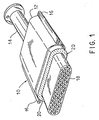
- FIG. 1 One illustrative form of a device for treating exhaust gases is designated by the numeral 10 in FIG. 1 .
- the mounting mat is not intended to be limited to use in the device shown in FIG. 1 , and so the shape is shown only as an illustrative embodiment. In fact, the mounting mat could be used to mount or support any fragile structure suitable for treating exhaust gases, such as a diesel catalyst structure, a diesel particulate trap, or the like.
- Catalytic converter 10 may include a generally tubular housing 12 formed of two pieces of metal, for example, high temperature resistant steel, held together by flange 16.
- the housing may include a preformed canister into which a mounting mat-wrapped fragile structure is inserted.
- Housing 12 includes an inlet 14 at one end and an outlet (not shown) at its opposite end. The inlet 14 and outlet are suitably formed at their outer ends whereby they may be secured to conduits in the exhaust system of an internal combustion engine.
- Device 10 contains a fragile structure, such as a frangible ceramic monolith 18, which is supported and restrained within housing 12 by a mounting mat 20.
- Monolith 18 includes a plurality of gas pervious passages that extend axially from its inlet end surface at one end to its outlet end surface at its opposite end.
- Monolith 18 may be constructed of any suitable refractory metal or ceramic material in any known manner and configuration.
- Monoliths are typically oval or round in cross-sectional configuration, but other shapes are possible.
- the monolith is spaced from inner surfaces of the housing by a distance or a gap, which may vary according to the type and design of the device utilized, for example, a catalytic converter, a diesel catalyst structure, or a diesel particulate trap.
- This gap is filled with a mounting mat 20 to provide resilient support to the ceramic monolith 18.
- the resilient mounting mat 20 provides both thermal insulation to the external environment and mechanical support to the fragile structure, thereby protecting the fragile structure from mechanical shock across a wide range of exhaust gas treatment device operating temperatures.
- the mounting mat includes inorganic fibers, optionally intumescent material, and binder.
- the composition of the mounting mat 20 is sufficient to provide a holding pressure capability to resiliently hold the fragile catalyst support structure 18 within a housing 12 of an exhaust gas treatment device 10 throughout a wide temperature range.
- any heat resistant inorganic fibers may be utilized in the mounting mat so long as the fibers can withstand the mounting mat forming process, can withstand the operating temperatures of the exhaust gas treatment devices, and provide the minimum holding pressure performance for holding fragile structure within the exhaust gas treatment device housing at the operating temperatures.
- suitable inorganic fibers that may be used to prepare the mounting mat and exhaust gas treatment device include high alumina polycrystalline fibers, refractory ceramic fibers such as alumino-silicate fibers, alumina-magnesia-silica fibers, kaolin fibers, alkaline earth silicate fibers such as calcia-magnesia-silica fibers and magnesia-silica fibers, S-glass fibers, S2-glass fibers, E-glass fibers, quartz fibers, silica fibers and combinations thereof.
- the heat resistant inorganic fibers that are used to prepare the mounting mat comprise ceramic fibers.
- suitable ceramic fibers include alumina fibers, alumina-silica fibers, alumina-zirconia-silica fibers, zirconia-silica fibers, zirconia fibers and similar fibers.
- a useful alumina-silica ceramic fiber is commercially available from Unifrax I LLC (Niagara Falls, New York) under the registered trademark FIBERFRAX.
- the FIBERFRAX ceramic fibers comprise the fiberization product of about 45 to about 75 weight percent alumina and about 25 to about 55 weight percent silica.
- the FIBERFRAX fibers exhibit operating temperatures of up to about 1540°C and a melting point up to about 1870°C.
- the FIBERFRAX fibers are easily formed into high temperature resistant sheets and papers.
- the alumina/silica fiber may comprise from about 40 weight percent to about 60 weight percent Al 2 O 3 and about 60 weight percent to about 40 weight percent SiO 2 .
- the fiber may comprise about 50 weight percent Al 2 O 3 and about 50 weight percent SiO 2
- the alumina/silica/magnesia glass fiber typically comprises from about 64 weight percent to about 66 weight percent SiO 2 from about 24 weight percent to about 25 weight percent Al 2 O 3 , and from about 9 weight percent to about 10 weight percent MgO.
- the E-glass fiber typically comprises from about 52 weight percent to about 56 weight percent SiO 2 , from about 16 weight percent to about 25 weight percent CaO, from about 12 weight percent to about 16 weight percent Al 2 O 3 , from about 5 weight percent to about 10 weight percent B 2 O 3 up to about 5 weight percent MgO, up to about 2 weight percent of sodium oxide and potassium oxide and trace amounts of iron oxide and fluorides, with a typical composition of 55 weight percent SiO 2 , 15 weight percent Al 2 O 3 , 7 weight percent B 2 O 3 , 3 weight percent MgO, 19 weight percent CaO and traces of the above mentioned materials.
- the biosoluble alkaline earth silicate fibers may comprise the fiberization product of a mixture of oxides of magnesium and silica. These fibers arc commonly referred to as magnesium-silicate fibers.
- the magnesium-silicate fibers generally comprise the fiberization product of about 60 to about 90 weight percent silica, from greater than 0 to about 35 weight percent magnesia and 5 weight percent or less impurities.
- the heat treated alkaline earth silicate fibers comprise the fiberization product of about 65 to about 86 weight percent silica, about 14 to about 35 weight percent magnesia and 5 weight percent or less impurities.
- the heat treated alkaline earth silicate fibers comprise the fiberization product of about 70 to about 86 weight percent silica, about 14 to about 30 weight percent magnesia, and 5 weight percent or less impurities.
- a suitable magnesium-silicate fiber is commercially available from Unifrax I LLC (Niagara Falls, New York) under the registered trademark ISOFRAX.
- Commercially available ISOFRAX fibers generally comprise the fiberization product of about 70 to about 80 weight percent silica, about 18 to about 27 weight percent magnesia and 4 weight percent or less impurities.
- the biosoluble alkaline earth silicate fibers may comprise the fiberization product of a mixture of oxides of calcium, magnesium and silica. These fibers are commonly referred to as calcia-magnesia-silica fibers. According to certain embodiments, the calcia-magnesia-silica fibers comprise the fiberization product of about 45 to about 90 weight percent silica, from greater than 0 to about 45 weight percent calcia, from greater than 0 to about 35 weight percent magnesia, and 10 weight percent or less impurities.
- Useful calcia-magnesia-silicate fibers are commercially available from Unifrax I LLC (Niagara Falls, New York) under the registered trademark INSULFRAX.
- INSULFRAX fibers generally comprise the fiberization product of about 61 to about 67 weight percent silica, from about 27 to about 33 weight percent calcia, and from about 2 to about 7 weight percent magnesia.
- Other suitable calcia-magnesia-silicate fibers are commercially available from Thermal Ceramics (Augusta, Georgia) under the trade designations SUPERWOOL 607, SUPERWOOL 607 MAX and SUPERWOOL HT.
- SUPERWOOL 607 fibers comprise about 60 to about 70 weight percent silica, from about 25 to about 35 weight percent calcia, from about 4 to about 7 weight percent magnesia, and trace amounts of alumina.
- SUPERWOOL 607 MAX fibers comprise about 60 to about 70 weight percent silica, from about 16 to about 22 weight percent calcia, and from about 12 to about 19 weight percent magnesia, and trace amounts of alumina.
- SUPERWOOL HT fiber comprise about 74 weight percent silica, about 24 weight percent calcia and trace amounts of magnesia, alumina and iron oxide.
- Suitable silica fibers useful in the production of a mounting mat for an exhaust gas treatment device include those leached glass fibers available from BelChem Fiber Materials GmbH, Germany, under the trademark BELCOTEX, from Hitco Carbon Composites, Inc. of Gardena California, under the registered trademark REFRASIL, and from Polotsk-Steklovolokno, Republic of Belarus, under the designation PS-23(R).
- the BELCOTEX fibers are standard type, staple fiber pre-yarns. These fibers have an average fineness of about 550 tex and are generally made from silicic acid modified by alumina.
- the BELCOTEX fibers are amorphous and generally contain about 94.5 silica, about 4.5 percent alumina, less than 0.5 percent sodium oxide, and less than 0.5 percent of other components. These fibers have an average fiber diameter of about 9 microns and a melting point in the range of 1500° to 1550°C. These fibers are heat resistant to temperatures of up to 1100°C, and are typically shot free and binder free.
- the REFRASIL fibers like the BELCOTEX fibers, are amorphous leached glass fibers which have a high silica content for providing thermal insulation for applications in the 1000° to 1100°C temperature range. These fibers are between about 6 and about 13 microns in diameter, and have a melting point of about 1700°C, The fibers, after leaching, typically have a silica content of about 95 percent by weight. Alumina may be present in an amount of about 4% by weight with other components being present in an amount of 1% or loss.
- the intumescent material that may be incorporated into the mounting mat includes, without limitation, unexpanded vermiculite, ion-exchanged vermiculite, heat treated vermiculite, expandable graphite, hydrobiotite, water-swelling tetrasilicic flourine mica, alkaline metal silicates, or mixtures thereof.
- the mounting mat may include a mixture of more than one type of intumescent material.
- the intumescent material may comprise a mixture of unexpanded vermiculite and expandable graphite in a relative amount of about 9:1 to about 1:2 vermiculite:graphite, as described in U.S. Patent No. 5,384,188 .
- the mounting mat also includes a binder or mixture of more than one type of binder. Suitable binders include organic binders, inorganic binders and mixtures of these two types of binders. According to certain embodiments, the intumescent mounting mat, includes one or more organic binders.
- the organic binders may be provided as a solid, a liquid, a solution, a dispersion, a latex, an emulsion, or similar form.
- the organic binder may comprise a thermoplastic or thermoset binder, which after cure is a flexible material that can be burned out of an installed mounting mat.
- suitable organic binders include, but are not limited to, acrylic latex, (meth)acrylic latex, copolymers of styrene and butadiene, vinylpyridine, acrylonitrile, copolymers of acrylonitrile and styrene, vinyl chloride, polyurethane, copolymers of vinyl acetate and ethylene, polyamides, silicones, and the like.
- Other resins include low temperature, flexible thermosetting resins such as unsaturated polyesters, epoxy resins and polyvinyl esters.
- the organic binder may be included in the mounting mat in an amount of greater than 0 to about 20 weight percent, from about 2.5 to about 15 weight percent, from about 5 to about 12.5 weight percent or from about 7.5 to about 10 weight percent, based on the total weight of the mounting mat.
- the mounting mat may include polymeric binder fibers instead of, or in addition to, a resinous or liquid binder. These polymeric binder fibers may be used in amounts to aid in binding the heat resistant inorganic fibers together. Suitable examples of binder fibers include polyvinyl alcohol fibers, polyolefin fibers such as polyethylene and polypropylene, acrylic fibers, polyester fibers, ethyl vinyl acetate fibers, nylon fibers and combinations thereof.
- the organic binder is a sacrificial binder employed to initially bond the fibers together.
- sacrificial it is meant that the organic binder will eventually be burned out of the mounting mat, leaving only the inorganic fibers, optionally intumescent material and optionally clay as the mounting mat for supporting the fragile structure within the metallic housing.
- the mounting mats may also include inorganic binder material.
- suitable inorganic binder materials include colloidal dispersions of alumina, silica, zirconia, and mixtures thereof.
- the mounting mat may be produced in any way known in the art for forming sheet-like materials.
- conventional paper-making processes either hand laid or machine laid, may be used to prepare the intumescent sheet material.
- a handsheet mold, a Fourdrinier paper machine, or a rotoformer paper machine can be employed to make the intumescent sheet material.
- the inorganic fibers, intumescent material, and antioxidant may be mixed together with a binder or other fibers capable of acting as a binder to form a mixture or slurry.
- the slurry of components may be flocculated by adding a flocculating agent to the slurry.
- the flocculated mixture or slurry is placed onto a papermaking machine to be formed into a ply or sheet of fiber containing paper.
- the sheet is dried by air drying or oven drying.
- the plies or sheets may be formed by vacuum casting the slurry.
- the slurry of components is wet laid onto a pervious web.
- a vacuum is applied to the web to extract the majority of the moisture from the slurry, thereby forming a wet sheet.
- the wet plies or sheets are then dried, typically in an oven.
- the sheet may be passed through a set of rollers to compress the sheet prior to drying.
- the fibers may be processed into a mounting mat by conventional means such as dry air layering.
- the mat at this stage has very little structural integrity and is very thick relative to conventional catalytic converter and diesel trap mounting mats.
- the resultant mat can therefore be dry needled, as is commonly known in the art, to densify the mat and increase its strength.
- the mat may be alternatively processed by the addition of a binder to the mat by impregnation to form a discontinuous fiber composite.
- the binder is added after formation of the mat, rather than forming the mat prepreg as noted hereinabove with respect to the conventional papermaking technique. This method of preparing the mat aids in maintaining fiber length by reducing breakage.
- a reinforcing coating is applied to a surface of the mounting mat.
- the reinforcing coating is applied to one of the major surfaces of the mounting mat.
- the reinforcing coating may be applied to both major surfaces.
- the reinforcing coating may be applied in a continuous pattern.
- the reinforcing coating is applied in a continuous fashion on one or both major surfaces of the mounting mat.
- the continuous coating is applied to the surface of the mounting mat in a substantially uniform manner across the entire surface of the mounting mat.
- the reinforcing coating that is applied to one or both major surfaces of the mounting mat generally comprises an organic material.
- the organic material of the reinforcing coating is separate than the sacrificial organic binder material that is included within the mounting mat.
- the reinforcing coating comprises an organic latex.
- Organic latex that may be used as the reinforcing layer comprises an acrylic latex.
- a suitable acrylic latex that may be used as the reinforcing coating is commercially available from (Lubrizol Advanced Materials, Inc.; Cleveland, Ohio, USA) under the trade designation HYCAR26083.
- the reinforcing coating is applied to the mounting mat in an amount sufficient to increase the crack resistance of the mounting mat as compared to the same mounting mat without the reinforcing coating. While the reinforcing coating is applied to the mounting mat in an amount sufficient to increase the crack resistance of the mat, the presence of the reinforcing coating does not appreciably alter or affect the performance properties of the mounting mat (ic, holding pressure performance, cold friction, cold compression, etc).
- the reinforcing coating comprising the acrylic latex is applied to the mounting mat in an amount from about 0.01 to about 2 weight percent based on the dry weight of the mounting mat. Without limitation, and merely by way of illustration, the acrylic latex is applied to the mounting mat at an amount of about 0.25 weight percent based on the total dry weight of said mounting mat.
- the reinforcing coating includes a suitable antioxidant additive.
- suitable antioxidant materials include primary antioxidants, secondary antioxidants, multifunctional antioxidants, and combinations thereof.
- primary antioxidants include sterically hindered phenolics and secondary aromatic amines.
- Suitable sterically hindered phenolics are commercially available from Elikochem (Villejust, France) under the trade designation Wingstay, from RT Vanderbilt (Norwalk CT) under the trade designations Agerite Resin and Vanox, and from Ciba Specialty Chemicals (High Point, NC) under the trade designation Irganox.
- secondary antioxidants include organophosphorus compounds which decompose peroxides and hydroperoxides into stable, non-radical products and thiosynergists which are very efficient for long-term thermal aging applications.
- Multifunctional antioxidants optimally combine primary and secondary antioxidant functions in one antioxidant compound.
- blends of hindered phenolics and thiosynergst antioxidants may be used as the antioxidant material for the exhaust gas treatment device mounting mat.
- the antioxidant material may be provided in the form of dispersions or emulsions of primary or mixtures of primary and secondary antioxidants.
- Suitable antioxidant dispersions are commercially available from Akron Dispersions (Akron, Ohio) under the trade designation Bostex, from Aquaspersions (West Yorkshire, UK) under the trade designation Aquanox, from Tiarco Chemical (Dalton, GA) under the trade designation Octolite, and from Great Lakes Chemical Co. (Indianapolis, IN) under the trade designations Lowinx, Durad and Anox.
- antioxidant dispersions include Bostex 24, which is a dispersion of Wingstay L and Bostex 362A, which is 50% Wingstay L / DTDTDP synergist (a thiosynergist/secondary antioxidant).
- the thermal degradation temperature for Wingstay L is greater than about 300°C and the autoignition temperature is about 440°C.
- a particularly suitable antioxidant is commercially available from Akron Dispersions (Akron, Ohio) under the trade designation Bostex 362A. According to certain illustrative embodiments, the antioxidant material is pre-complexed with the organic binder material prior to addition to the remaining components of the mounting mat.
- the reinforcing coating material may also include a coating detection additive.
- the coating detection additive comprises an ultra-violet light detectable dye.
- the ultra-violet light detectable dye may be included in the reinforcing coating composition in an amount from about 0.01 to about 0.5 weight percent based on the dry weight of the mounting mat. According to certain illustrative embodiments, the ultra-violet light detectable dye is present in an amount of about 0.03 weight percent based on the total weight of said mounting mat.
- the flexible reinforcing coating may be applied to the one or more major surfaces of the mounting mat by one of brushing, dipping, immersing, or spraying.
- the flexible reinforcing coating may be applied to the one or more major surfaces of the mounting mat by a spray coating process.
- the spray coating process involves the use of a plurality of spray nozzles to provide a light, but uniform reinforcing coating across the surface(s) of the mounting mat.
- the spray coating process permits the application of a very light coating of the reinforcing coating, such as an acrylic latex, to the surfaces of the mounting mat.
- the layer of reinforcing coating is applied in an amount that does not appreciably alter or compromise the thermal insulation, the holding pressure performance, the cold compression performance, and the cold friction performance of the mounting mat.
- the reinforcing coating is applied at a level to impart substantial crack resistance to the mounting mat. Thus, neither the total binder content or the thickness of the mounting mat are substantially increased.
- the mounting mat may comprise one or more layers.
- the mounting mat may comprise one non-intumescent layer or one intumescent layer.
- the mounting mat may comprise multiple layers comprising more than one non-intumescent layer or more than one intumescent layer.
- the mounting mat may comprise multiple layers comprising a combination of at least one non-intumescent layer and at least one intumescent layer.
- Further embodiments of the mounting mat may comprise multiple layers comprising at least one intumescent layer that is sandwiched between at least two non-intumescent layers.
- Further embodiments of the mounting mat may comprise multiple layers comprising at least one non-intumescent layer sandwiched between at least two intumescent layers.
- the reinforcing coating layer may be applied to one or more of the major surfaces of only one of the layers of the mounting. Alternatively, the reinforcing coating layer may be applied to one or more of the major surfaces of more than one of the layers of the mounting mat composite. According to certain embodiments, the reinforcing coating layer may be applied to one or more of the major surfaces of each of the layers of the composite mounting mat.
- the coated mounting mat can be cut, such as by die stamping, to form mounting mats of exact shapes and sizes with reproducible tolerances.
- the mounting mat 20 exhibits suitable handling properties upon densification as by needling or the like, meaning it can be easily handled and is not so brittle as to crumble in one's hand like many other fiber blankets or mats. It can be easily and flexibly fitted or wrapped around the fragile structure 18 or like fragile structure without cracking, and then disposed within the catalytic converter housing 12.
- the mounting mat-wrapped fragile structure can be inserted into a housing or the housing can be built or otherwise fabricated around the mounting mat-wrapped fragile structure.
- a sample reinforcing coating was prepared with 95% water, 4.5% HYCAR 26083 acrylic latex, and 0.5% BOSTEX 362A antioxidant.
- a layer of the reinforcing coating (0.25% of mat weight) was spray coated onto the mat to substantially increase the crack resistance.
- a 0.03% level of UV dye was included in the acrylic latex so that a determination of amount coated could be made using a UV detector.
- the mat used for the testing was a sample of an intumescent exhaust gas treatment devices mounting mat commercially available under the registered trademark ISOMAT® AV5 from Unifrax I LLC (Niagara Falls, NY, USA).
- the sample mats are comprised of biosoluble inorganic fibers, vermiculite and sacrificial organic binder, and has a basis weight of about 2900 g/m 2 .
- the force (in Newtons) to crack the uncoated mat was from 2 to 17 N.
- the amount of force required to crack the mounting mat was at least 250N. Therefore, the reinforcing coating layer imparted a substantial crack resistance as compared to uncoated mats of identical composition.
- intumescent mounting mats with and without the application of a reinforcing coating were subjected to mechanical cycling.
- the test mats were placed between two heated blocks.
- the two blocks are heated to different temperatures as shown in Table II.
- the top heated block is moved to open the gap by either 1% or 3% of the initial gap width and then closed over a given period of time wherein the gap was opened (a "cycle"). After 1000 cycles, the residual minimum holding pressure exerted by the mounting mat was calculated.
- the mounting mats having the crack resistant coating applied thereon achieve a Pmin 1000 of greater than 50 kPa as tested.
- the holding pressure performance of the mounting mat having a reinforcing coating applied thereon was virtually identical to the performance of the mounting mats without the reinforcing coating.
- the push-out force is a measure of the amount of force required to push the fragile catalyst support structure or substrate (ie, the monolith) out of the exhaust gas treatment device outer housing.
- the exhaust gas treatment device is assembled by positioning the mounting mat around the fragile catalyst support structure and locating the fragile catalyst support structure within the housing with the mounting mat disposed in the gap between the fragile catalyst support structure and the outer steel housing.
- the fragile catalyst support structures were wrapped with the mounting mat and installed in the outer steel housing using a commonly performed canning technique known as tourniquet mounting.
- the housing used on this test was stainless steel SS409 housing.
- the fragile catalyst support structure was then pushed out of the housing using mechanical testing equipment, such as the Instron or MTS. The amount of force needed to push the fragile catalyst support structure out of the outer steel housing was recorded. This test was performed on a mounting mat that was treated with the reinforcing coating on the interior shell or housing side of an exhaust gas treatment device, on the substrate side of the fragile structure, and on a mounting mat that was not treated with the reinforcing coating. The results of this testing are set forth in Table III below. Table III Sample Coating Coated Side Gap (mm) Gap Bulk Density (g/cm 3 ) Push-Out Force (N) 1 Yes Interior shell 4.32 0.66 4060 2 Yes Substrate side 4.26 0.67 4247 3 No Not Coated 4.44 0.65 4202
- intumescent mounting mats with and without the reinforcing coating were cut into 5.08 cm (2 inch) by 5.08 cm (2 inch) samples. The basis weight of the samples was measured and recorded. A sample of mat was placed between two plates and was held at room temperature. A target gap was calculated based on the target gap bulk density of the mat being tested. The top plate of the test apparatus was lowered at 25.4 mm/minute until the target gap was reached. The peak pressure once the target gap was reached was measured. The mat was held at the target gap for 300 seconds and the residual pressure was measured.
- Table IV Sample Cold Compression 0.5 gbd Cold Compression Peak 0.75 gbd Target >125 kPa ⁇ 1600 kPa C1 (no coating) 153 1240 2 (coating) 147 1232
- intumescent mounting mats with and without the reinforcing coating were cut into 2 inch by 2 inch samples. The weights of the mat samples were measured and recorded. A pair of mat samples were aligned with a piece of stainless steel plate located between them, and this assembly was placed in a vise. The vise was closed with enough force to reach the target gap bulk density, and the peak load was recorded. After a 5 minute period, the residual load was measured and recorded. The stainless steel plate was pushed down between the mat samples and the force exerted during this displacement was recorded.
- Table V Sample Cold Friction Steel 0.5 gbd Cold Friction Steel 0.75 gbd C1 (no coating) 0.257 0.25 2 (coating) 0.265 0.241
- a tray having the dimensions of about 38.1 cm (15 inches) long by about 152.4 cm (60 inches) wide was divided into a plurality of substantially equal size compartments.
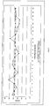
- An approximately 5.08 cm (2 inch) by 5.08 cm (2 inch) piece of commercially available exhaust gas treatment device mounting mat comprising inorganic fibers and no organic binder sold by Unifrax I LLC (Niagara Falls, NY, USA) under the trade designation CC-MAX 8 HP were weighed and placed within each compartment of the tray. The tray was placed on the coating machine in a position that would be occupied by a mounting mat during normal commercial production.
- the coating system was turned on and the reinforcing coating comprising an organic latex was applied to the surfaces of the mounting mat pieces located within the tray for a known length of time. The amount and distribution of the reinforcing latex coating applied to the mounting mat pieces was determined. The amount of the reinforcing latex coating is reported in FIG. 2 as LOI Added and the distribution of the reinforcing latex coating across all of the pieces of mounting mat within the tray is reported as Avg. LOI Added.
- the mounting mats can be die cut and are operable as resilient supports in a thin profile, providing ease of handling, and in a flexible form, so as to be able to provide a total wrap of the catalyst support structure, if desired, without cracking.
- the mounting mat may be integrally wrapped about the entire circumference or perimeter of at least a portion of the catalyst support structure.
- the mounting mat may also be partially wrapped and include an end-seal as currently used in some conventional converter devices, if desired, to prevent gas by-pass.
- the mounting mats described above are also useful in a variety of applications such as conventional automotive catalytic converters for, among others, motorcycles and other small engine machines, and automotive pre-converters, as well as high temperature spacers, gaskets, and even future generation automotive underbody catalytic converter systems.
- the mounting mats described above can also be used in catalytic converters employed in the chemical industry which are located within exhaust or emission stacks, including those which contain fragile honeycomb type structures that need to be protectively mounted.
Landscapes
- Life Sciences & Earth Sciences (AREA)
- Engineering & Computer Science (AREA)
- Wood Science & Technology (AREA)
- Exhaust Gas After Treatment (AREA)
Applications Claiming Priority (2)
| Application Number | Priority Date | Filing Date | Title |
|---|---|---|---|
| US17039109P | 2009-04-17 | 2009-04-17 | |
| PCT/US2010/001149 WO2010120380A2 (en) | 2009-04-17 | 2010-04-16 | Exhaust gas treatment device |
Publications (3)
| Publication Number | Publication Date |
|---|---|
| EP2419613A2 EP2419613A2 (en) | 2012-02-22 |
| EP2419613A4 EP2419613A4 (en) | 2013-12-18 |
| EP2419613B1 true EP2419613B1 (en) | 2016-08-17 |
Family
ID=42981115
Family Applications (1)
| Application Number | Title | Priority Date | Filing Date |
|---|---|---|---|
| EP10764780.2A Not-in-force EP2419613B1 (en) | 2009-04-17 | 2010-04-16 | Exhaust gas treatment device |
Country Status (6)
| Country | Link |
|---|---|
| US (1) | US8075843B2 (enExample) |
| EP (1) | EP2419613B1 (enExample) |
| JP (3) | JP2012524206A (enExample) |
| CN (1) | CN102459834B (enExample) |
| WO (1) | WO2010120380A2 (enExample) |
| ZA (1) | ZA201107571B (enExample) |
Families Citing this family (16)
| Publication number | Priority date | Publication date | Assignee | Title |
|---|---|---|---|---|
| US8517083B2 (en) * | 2007-12-14 | 2013-08-27 | Refractory Specialties, Incorporated | System, apparatus and method for manufacturing metal ingots |
| JP5256881B2 (ja) * | 2008-06-25 | 2013-08-07 | いすゞ自動車株式会社 | 排気ガス浄化装置 |
| GB0906837D0 (en) | 2009-04-21 | 2009-06-03 | Saffil Automotive Ltd | Mats |
| WO2012021817A2 (en) | 2010-08-12 | 2012-02-16 | Unifrax I Llc | Exhaust gas treatment device |
| DK2603676T3 (en) | 2010-08-13 | 2016-04-25 | Unifrax I Llc | Flexible mounting mat with edge protection and exhaust gas treatment device including the mat assembly |
| CN103547777A (zh) | 2010-11-11 | 2014-01-29 | 尤尼弗瑞克斯I有限责任公司 | 安装垫和废气处理装置 |
| JP5971894B2 (ja) | 2011-01-31 | 2016-08-17 | スリーエム イノベイティブ プロパティズ カンパニー | 汚染コントロール要素用保持材、その製造方法及び汚染コントロール装置 |
| MY172117A (en) | 2013-07-22 | 2019-11-14 | Morgan Advanced Mat Plc | Inorganic fibre compositions |
| JP2016050559A (ja) * | 2014-09-02 | 2016-04-11 | トヨタ自動車株式会社 | 触媒コンバータ装置 |
| CN106285889A (zh) * | 2015-05-21 | 2017-01-04 | 天津拓霖科技有限公司 | 一种排气管隔热带 |
| KR101724480B1 (ko) * | 2015-10-28 | 2017-04-07 | 현대자동차 주식회사 | 차량용 배기 시스템의 후처리 장치 |
| CN105422192A (zh) * | 2015-12-09 | 2016-03-23 | 天津雷沃动力有限公司 | 一种金属材质柴油发动机隔热总成 |
| WO2017121770A1 (en) | 2016-01-15 | 2017-07-20 | Thermal Ceramics Uk Limited | Apparatus and method for forming melt-formed inorganic fibres |
| GB201616662D0 (en) | 2016-09-30 | 2016-11-16 | Morgan Advanced Materials Plc | Inorganic Fibre compositions |
| JP6678691B2 (ja) * | 2018-02-27 | 2020-04-08 | 本田技研工業株式会社 | 排気浄化装置 |
| GB2591039B (en) | 2020-10-23 | 2021-11-24 | Thermal Ceramics Uk Ltd | Thermal insulation |
Family Cites Families (150)
| Publication number | Priority date | Publication date | Assignee | Title |
|---|---|---|---|---|
| US461176A (en) * | 1891-10-13 | Pocket savings-bank | ||
| US3458329A (en) * | 1963-02-13 | 1969-07-29 | Minnesota Mining & Mfg | Ceramic greensheets |
| US3224927A (en) | 1963-10-04 | 1965-12-21 | Du Pont | Forming inorganic fiber material containing cationic starch and colloidal silica |
| GB1291567A (en) * | 1968-12-16 | 1972-10-04 | Thomas Gordon Mcnish | Improvements in or relating to fibrous insulating materials |
| US3771967A (en) | 1971-12-14 | 1973-11-13 | Tenneco Inc | Catalytic reactor with monolithic element |
| US3798006A (en) * | 1971-12-14 | 1974-03-19 | Tenneco Inc | Catalytic converter for exhuast gases |
| US4335077A (en) * | 1972-03-21 | 1982-06-15 | Zeuna-Staerker Kg | Catalyzer for detoxifying exhaust gases from internal combustion engines |
| GB1438762A (en) | 1972-06-28 | 1976-06-09 | Ici Ltd | Fluid treatment vessel |
| DE2233886C3 (de) * | 1972-07-10 | 1985-04-18 | Kali-Chemie Ag, 3000 Hannover | Vorrichtung zur katalytischen Reinigung der Abgase von Brennkraftmaschinen |
| US4093423A (en) * | 1972-10-03 | 1978-06-06 | Volkswagenwerk Aktiengesellschaft | Catalytic device for the catalytic purification of exhaust gases |
| GB1455563A (en) | 1972-11-29 | 1976-11-17 | Ici Ltd | Fibrous mater-als |
| US3916057A (en) * | 1973-08-31 | 1975-10-28 | Minnesota Mining & Mfg | Intumescent sheet material |
| CA1042587A (en) | 1974-11-04 | 1978-11-14 | Minnesota Mining And Manufacturing Company | Intumescent sheet material |
| DE7541252U (de) * | 1975-12-24 | 1976-04-29 | Paul Gillet Gmbh, 6732 Edenkoben | Vorrichtung zum reinigen der abgase von brennkraftmaschinen |
| US4048363A (en) * | 1976-06-16 | 1977-09-13 | Minnesota Mining And Manufacturing Company | Offset laminated intumescent mounting mat |
| US4142864A (en) * | 1977-05-31 | 1979-03-06 | Engelhard Minerals & Chemicals Corporation | Catalytic apparatus |
| US4204907A (en) * | 1978-03-29 | 1980-05-27 | The Carborundum Company | Conditioned colloidal silica post impregnant to prevent binder migration |
| US4332852A (en) * | 1978-03-29 | 1982-06-01 | Kennecott Corporation | Conditioned colloidal silica post impregnant to prevent binder migration in the production of insulation articles comprising randomly oriented refractory fibers |
| US4156533A (en) * | 1978-04-28 | 1979-05-29 | Minnesota Mining And Manufacturing Company | High temperature gasket |
| US4279864A (en) * | 1978-12-04 | 1981-07-21 | Nippon Soken, Inc. | Monolithic catalyst converter |
| US4239733A (en) | 1979-04-16 | 1980-12-16 | General Motors Corporation | Catalytic converter having a monolith with support and seal means therefor |
| US4269807A (en) * | 1979-10-22 | 1981-05-26 | Uop Inc. | Catalytic converter mounting arrangement for reducing bypass leakage |
| US4305992A (en) | 1979-11-28 | 1981-12-15 | Minnesota Mining And Manufacturing Company | Intumescent sheet material |
| US4271228A (en) * | 1980-02-04 | 1981-06-02 | Hollingsworth & Vose Company | Sheet material containing exfoliated vermiculite |
| JPS6027770Y2 (ja) * | 1980-03-07 | 1985-08-22 | 日産自動車株式会社 | 触媒式排気後処理装置のガスシ−ル保護構造 |
| JPS6055474B2 (ja) * | 1981-09-30 | 1985-12-05 | イソライト・バブコツク耐火株式会社 | セラミツクフアイバ−成形品の改良法 |
| US4385135A (en) * | 1982-05-26 | 1983-05-24 | Minnesota Mining And Manufacturing Company | Intumescent sheet material containing low density fillers |
| US4617176A (en) | 1984-09-13 | 1986-10-14 | Minnesota Mining And Manufacturing Company | Catalytic converter for automotive exhaust system |
| JPS6177654A (ja) * | 1984-09-20 | 1986-04-21 | トヨタ自動車株式会社 | 触媒担体支持用耐熱高膨張性シ−ト状物およびその製造方法 |
| US4863700A (en) * | 1985-04-16 | 1989-09-05 | Stemcor | Monolithic catalytic converter mounting arrangement |
| US4752515A (en) * | 1985-06-17 | 1988-06-21 | Mitsubishi Chemical Industries | Alumina fiber structure |
| FR2585071B1 (fr) * | 1985-07-16 | 1987-11-27 | Peugeot Cycles | Pot d'echappement pour vehicule automobile ou analogue |
| US5332699A (en) * | 1986-02-20 | 1994-07-26 | Manville Corp | Inorganic fiber composition |
| US4797263A (en) * | 1986-03-06 | 1989-01-10 | General Motors Corporation | Monolithic catalytic converter with improved gas distribution |
| DE3700070A1 (de) * | 1987-01-02 | 1988-07-14 | Eberspaecher J | Vorrichtung fuer die katalytische reinigung von fahrzeugmotor-abgasen |
| US4786670A (en) | 1987-01-09 | 1988-11-22 | Lydall, Inc. | Compressible non-asbestos high-temperature sheet material usable for gaskets |
| US4865818A (en) * | 1987-08-17 | 1989-09-12 | Minnesota Mining And Manufacturing Co. | Catalytic converter for automotive exhaust system |
| US4985212A (en) * | 1987-09-29 | 1991-01-15 | Kabushiki Kaisha Toshiba | Support apparatus for a ceramic honeycomb element |
| CA1310275C (en) | 1987-12-04 | 1992-11-17 | Richard P. Merry | Catalytic converter particulate filter for exhaust systems |
| US4929429A (en) * | 1988-02-11 | 1990-05-29 | Minnesota Mining And Manufacturing Company | Catalytic converter |
| US5242871A (en) * | 1988-02-29 | 1993-09-07 | Nippon Pillar Packing Co., Ltd. | Heat-resistant expansion member |
| JPH0243955A (ja) | 1988-08-02 | 1990-02-14 | Ngk Insulators Ltd | ハニカム構造体およびその製造法 |
| US5008086A (en) * | 1988-10-28 | 1991-04-16 | Minnesota Mining And Manufacturing Company | Erosion resistant mounting composite for catalytic converter |
| US5119551A (en) * | 1989-02-06 | 1992-06-09 | Tennessee Gas Pipeline Company | Method of making a catalytic converter with one piece housing |
| DE3908887A1 (de) * | 1989-03-17 | 1990-09-20 | Eberspaecher J | Vorrichtung zur katalytischen entgiftung oder dgl. von verbrennungsmotor-abgasen mit zwei abgas-behandlungskoerpern und einem schutzring dazwischen |
| US4999168A (en) * | 1989-05-01 | 1991-03-12 | The Carborundum Company | Crack resistant intumescent sheet material |
| US5032441A (en) * | 1989-05-01 | 1991-07-16 | The Carborundum Company | Intumescent conforming mounting pad |
| US5079280A (en) * | 1989-11-15 | 1992-01-07 | W. R. Grace & Co.-Conn. | Low temperature expandable vermiculite and intumescent sheet material containing same |
| GB9002256D0 (en) | 1990-02-01 | 1990-03-28 | Rendel Scient Services Limited | Fire protection |
| US5094074A (en) * | 1990-02-23 | 1992-03-10 | Nissan Motor Co., Ltd. | Catalytic converter with metallic carrier and method for producing same |
| US5258216A (en) | 1990-12-22 | 1993-11-02 | Bayer Aktiengesellschaft | Sheet-like structures capable of intumescence, their production |
| JPH0662932B2 (ja) | 1990-12-28 | 1994-08-17 | 日本ピラー工業株式会社 | 耐熱膨脹性部材 |
| KR100236883B1 (ko) * | 1991-01-17 | 2000-01-15 | 씨.디. 스웨트맨 | 염류용해성 무기섬유 |
| US5151253A (en) * | 1991-04-18 | 1992-09-29 | Minnesota Mining And Manufacturing Company | Catalytic converter having a monolith mounting of which is comprised of partially dehydrated vermiculite flakes |
| US5254410A (en) | 1991-04-18 | 1993-10-19 | Minnesota Mining & Manufacturing Company | Partially dehydrated vermiculite flakes and method of making same |
| US5145811A (en) * | 1991-07-10 | 1992-09-08 | The Carborundum Company | Inorganic ceramic papers |
| US5272874A (en) * | 1991-09-26 | 1993-12-28 | Dry Systems Technologies | Exhaust treatment system |
| US5250269A (en) * | 1992-05-21 | 1993-10-05 | Minnesota Mining And Manufacturing Company | Catalytic converter having a metallic monolith mounted by a heat-insulating mat of refractory ceramic fibers |
| US5389716A (en) * | 1992-06-26 | 1995-02-14 | Georgia-Pacific Resins, Inc. | Fire resistant cured binder for fibrous mats |
| US5376341A (en) | 1992-07-24 | 1994-12-27 | Corning Incorporated | Catalytic converter for motorcycles |
| US6183852B1 (en) * | 1992-09-15 | 2001-02-06 | The Boeing Company | Refractory fibrous ceramic insulation and process of making same |
| US5384188A (en) * | 1992-11-17 | 1995-01-24 | The Carborundum Company | Intumescent sheet |
| JP3479074B2 (ja) * | 1993-01-07 | 2003-12-15 | ミネソタ マイニング アンド マニュファクチャリング カンパニー | 可撓性不織マット |
| US5290522A (en) * | 1993-01-07 | 1994-03-01 | Minnesota Mining And Manufacturing Company | Catalytic converter mounting mat |
| CN100360472C (zh) * | 1993-01-15 | 2008-01-09 | 摩根坩埚有限公司 | 一种提供一种在升高的温度下使用的盐水可溶性耐熔纤维的方法 |
| US5811360A (en) * | 1993-01-15 | 1998-09-22 | The Morgan Crucible Company Plc | Saline soluble inorganic fibres |
| US5340643A (en) * | 1993-02-26 | 1994-08-23 | W. R. Grace & Co.-Conn. | Intumescent sheet material |
| US5332609A (en) * | 1993-03-25 | 1994-07-26 | Minnesota Mining And Manufacturing Company | Intumescent mounting mat |
| WO1994024425A1 (en) * | 1993-04-22 | 1994-10-27 | The Carborundum Company | Mounting mat for fragile structures such as catalytic converters |
| CA2131247C (en) | 1993-09-03 | 1998-07-07 | Minoru Machida | Ceramic honeycomb catalytic converter |
| US5453116A (en) * | 1994-06-13 | 1995-09-26 | Minnesota Mining And Manufacturing Company | Self supporting hot gas filter assembly |
| GB9414154D0 (en) | 1994-07-13 | 1994-08-31 | Morgan Crucible Co | Saline soluble inorganic fibres |
| US5569629A (en) | 1994-08-23 | 1996-10-29 | Unifrax Corporation | High temperature stable continuous filament glass ceramic fibers |
| EP0765993B1 (en) | 1995-04-13 | 2006-06-28 | Mitsubishi Chemical Corporation | Monolith holding material, method for producing the same, catalytic converter using the monolith, and method for producing the same |
| US5736109A (en) * | 1995-06-30 | 1998-04-07 | Minnesota Mining And Manufacturing Company | Intumescent sheet material and paste with organic binder |
| US5853675A (en) | 1995-06-30 | 1998-12-29 | Minnesota Mining And Manufacturing Company | Composite mounting system |
| CA2224325C (en) * | 1995-06-30 | 2007-07-31 | Minnesota Mining And Manufacturing Company | Intumescent sheet material |
| US5523059A (en) * | 1995-06-30 | 1996-06-04 | Minnesota Mining And Manufacturing Company | Intumescent sheet material with glass fibers |
| DE29515081U1 (de) | 1995-09-20 | 1997-01-23 | Leistritz AG & Co Abgastechnik, 90765 Fürth | Lagerungsmatte für einen Abgaskatalysator |
| US5928975A (en) * | 1995-09-21 | 1999-07-27 | The Morgan Crucible Company,Plc | Saline soluble inorganic fibers |
| AU703995B2 (en) * | 1995-10-30 | 1999-04-01 | Unifrax Corporation | High temperature resistant glass fiber |
| US6030910A (en) * | 1995-10-30 | 2000-02-29 | Unifrax Corporation | High temperature resistant glass fiber |
| WO1997032118A1 (en) | 1996-02-27 | 1997-09-04 | Imperial Chemical Industries Plc | Composite fibre products and processes for their production |
| EP0803643B1 (de) | 1996-04-27 | 2004-03-31 | Faurecia Abgastechnik GmbH | Abgaskatalysator |
| JP3318822B2 (ja) * | 1996-05-29 | 2002-08-26 | イビデン株式会社 | 排気ガス浄化用コンバーター用断熱シール材の取り付け方法とその取り付け治具 |
| US5882608A (en) * | 1996-06-18 | 1999-03-16 | Minnesota Mining And Manufacturing Company | Hybrid mounting system for pollution control devices |
| US6726884B1 (en) * | 1996-06-18 | 2004-04-27 | 3M Innovative Properties Company | Free-standing internally insulating liner |
| US20020025750A1 (en) * | 1996-07-26 | 2002-02-28 | Imperial Chemical Industries Plc. | Composite mat |
| EP0824184B1 (en) | 1996-08-14 | 2002-10-23 | Denso Corporation | Ceramic catalytic converter |
| US5955177A (en) * | 1996-09-03 | 1999-09-21 | 3M Innovative Properties Company | Fire barrier mat |
| EP0837229B1 (en) | 1996-10-15 | 2002-04-24 | Corning Incorporated | Method of making a catalytic converter for use in an internal combustion engine |
| US6051193A (en) * | 1997-02-06 | 2000-04-18 | 3M Innovative Properties Company | Multilayer intumescent sheet |
| AU6244398A (en) * | 1997-02-06 | 1998-08-26 | Minnesota Mining And Manufacturing Company | Multilayer intumescent sheet |
| US6923942B1 (en) * | 1997-05-09 | 2005-08-02 | 3M Innovative Properties Company | Compressible preform insulating liner |
| US6101714A (en) * | 1997-09-08 | 2000-08-15 | Corning Incorporated | Method of making a catalytic converter for use in an internal combustion engine |
| WO1999046028A1 (en) | 1998-03-11 | 1999-09-16 | Unifrax Corporation | Support element for fragile structures such as catalytic converters |
| ZA989387B (en) * | 1998-08-13 | 1999-04-15 | Unifrax Corp | High temperature resistant glass fiber |
| DE19853422A1 (de) * | 1998-11-19 | 2000-05-25 | Wacker Chemie Gmbh | Formkörper zur Lagerung eines Monolithen in einem Katalysator |
| JP4526187B2 (ja) * | 1998-12-08 | 2010-08-18 | ユニフラックス ワン リミテッド ライアビリティ カンパニー | 低温排出ガス処理装置用無定形非膨張性無機繊維マット |
| US6158120A (en) | 1998-12-14 | 2000-12-12 | General Motors Corporation | Method for making a catalytic converter containing a multiple layer mat |
| EP1056933B1 (de) * | 1998-12-16 | 2002-09-25 | Asglawo Gesellschaft mit beschränkter Haftung - Stoffe zum Dämmen und Verstärken | Lagerungsmatte für die lagerung eines abgaskatalysators |
| US6317976B1 (en) | 1998-12-28 | 2001-11-20 | Corning Incorporated | Method of making a catalytic converter for use in an internal combustion engine |
| AU6297099A (en) | 1999-06-08 | 2000-12-28 | 3M Innovative Properties Company | High temperature mat for a pollution control device |
| DE60003569T2 (de) * | 1999-09-10 | 2004-04-29 | The Morgan Crucible Co. Plc., Windsor | Hochtemperaturbeständige, in salzlösung lösliche fasern |
| GB0004681D0 (en) | 2000-02-28 | 2000-04-19 | Saffil Limited | Method of making fibre-based products and their use |
| US20020127154A1 (en) * | 2000-03-03 | 2002-09-12 | Foster Michael R. | Exhaust control device and method for manufacture thereof |
| DE60121555T8 (de) * | 2000-03-22 | 2007-10-31 | Ibiden Co., Ltd., Ogaki | Fixier- und Dichtmattenmaterial |
| JP2001280124A (ja) | 2000-03-31 | 2001-10-10 | Ngk Insulators Ltd | セル構造体収納容器及びそのアッセンブリ |
| JP2002066331A (ja) | 2000-08-25 | 2002-03-05 | Nichias Corp | 触媒担体保持部材及びその製造方法並びに触媒コンバータ |
| JP2002129455A (ja) * | 2000-10-17 | 2002-05-09 | Ibiden Co Ltd | 触媒コンバータ用保持シール材及びその製造方法、触媒コンバータ |
| DE10057158C1 (de) * | 2000-11-16 | 2002-03-28 | Asglawo Gmbh Stoffe Zum Daemme | Lagerungsmatte für die Lagerung eines Abgaskatalysators |
| WO2002053511A1 (en) | 2000-12-28 | 2002-07-11 | 3M Innovative Properties Company | Thermal insulating material and pollution control device using the same |
| US7261864B2 (en) * | 2001-06-22 | 2007-08-28 | 3M Innovative Properties Company | Catalyst carrier holding material and catalytic converter |
| JP4761655B2 (ja) | 2001-06-22 | 2011-08-31 | スリーエム イノベイティブ プロパティズ カンパニー | 触媒担体保持材及び触媒コンバータ |
| JP5059284B2 (ja) | 2001-10-09 | 2012-10-24 | スリーエム イノベイティブ プロパティズ カンパニー | 生体溶解性無機ファイバーと雲母バインダーとを含有する組成物 |
| GB2383793B (en) | 2002-01-04 | 2003-11-19 | Morgan Crucible Co | Saline soluble inorganic fibres |
| BR0302547B1 (pt) | 2002-01-10 | 2012-11-27 | fibra inorgánica vìtrea resistente a altas temperaturas e processo de fabricação de fibra inorgánica vìtrea resistente a altas temperaturas e processo de isolamento de um artigo. | |
| DE60320611T2 (de) | 2002-03-28 | 2009-06-10 | Nichias Corp. | Halterungsmaterial für einen katalytischen Umwandler und Verfahren zu seiner Herstellung |
| US7704459B2 (en) * | 2002-07-31 | 2010-04-27 | 3M Innovative Properties Company | Mat for mounting a pollution control element in a pollution control device for the treatment of exhaust gas |
| EP1546514B1 (en) * | 2002-09-30 | 2015-04-22 | Unifrax I LLC | Exhaust gas treatment device and method for making the same |
| JP2004196833A (ja) * | 2002-12-16 | 2004-07-15 | Toyo Ink Mfg Co Ltd | 紫外線照射により判別可能なインキ |
| GB0229380D0 (en) * | 2002-12-17 | 2003-01-22 | Saffil Ltd | Mats |
| CN100585138C (zh) | 2003-01-31 | 2010-01-27 | 3M创新有限公司 | 污染控制设备中的系统 |
| EP1464800A1 (en) * | 2003-04-02 | 2004-10-06 | 3M Innovative Properties Company | Exhaust system component having insulated double wall |
| US7854904B2 (en) * | 2003-06-10 | 2010-12-21 | 3M Innovative Properties Company | Mounting mat for a catalytic converter |
| EP1495807A1 (en) | 2003-06-30 | 2005-01-12 | 3M Innovative Properties Company | Mounting mat for mounting monolith in a pollution control device |
| JP2005093921A (ja) * | 2003-09-19 | 2005-04-07 | Canon Inc | 電界効果型有機トランジスタおよびその製造方法 |
| US7550118B2 (en) * | 2004-04-14 | 2009-06-23 | 3M Innovative Properties Company | Multilayer mats for use in pollution control devices |
| CN100462126C (zh) | 2004-05-18 | 2009-02-18 | 揖斐电株式会社 | 蜂窝结构体及废气净化装置 |
| JP2005350590A (ja) * | 2004-06-11 | 2005-12-22 | Toyo Ink Mfg Co Ltd | 紫外線照射により判別可能なインキ。 |
| BRPI0512698B8 (pt) * | 2004-06-29 | 2019-07-30 | Unifrax I Llc | dispositivo de tratamento de gás de exaustão e método de construção do mesmo |
| JP4663341B2 (ja) | 2005-01-25 | 2011-04-06 | イビデン株式会社 | 排気ガス浄化装置のエンドコーン部用断熱材 |
| JP4665618B2 (ja) | 2005-06-10 | 2011-04-06 | イビデン株式会社 | 保持シール材の製造方法 |
| ES2688274T3 (es) * | 2005-06-30 | 2018-10-31 | Unifrax I Llc | Fibra inorgánica revestida de fosfato y métodos de preparación y uso |
| US7854905B2 (en) | 2005-09-08 | 2010-12-21 | 3M Innovative Properties Company | Holding material for pollution control element and pollution control apparatus |
| CN101310096A (zh) | 2005-10-13 | 2008-11-19 | 3M创新有限公司 | 多层安装垫和包含该多层安装垫的污染控制装置 |
| GB0525375D0 (en) * | 2005-12-14 | 2006-01-18 | 3M Innovative Properties Co | Mounting mat for a pollution control device |
| JP4959206B2 (ja) * | 2006-03-02 | 2012-06-20 | イビデン株式会社 | 耐熱シートおよび排気ガス浄化装置 |
| JP4863828B2 (ja) | 2006-09-29 | 2012-01-25 | イビデン株式会社 | シート材、その製造方法および排気ガス処理装置 |
| JP5014113B2 (ja) | 2007-01-26 | 2012-08-29 | イビデン株式会社 | シート材、その製造方法、排気ガス処理装置および消音装置 |
| US20100115900A1 (en) | 2007-02-19 | 2010-05-13 | De Rovere Anne N | Flexible fibrous material, pollution control device, and methods of making the same |
| EP2173981B1 (en) * | 2007-06-13 | 2018-07-18 | 3M Innovative Properties Company | Securable mounting material and method of making and using the same |
| KR101547710B1 (ko) | 2007-06-13 | 2015-08-26 | 쓰리엠 이노베이티브 프로퍼티즈 컴파니 | 내침식성 장착 재료와 그 제조 및 사용 방법 |
| JP4922861B2 (ja) * | 2007-08-10 | 2012-04-25 | ニチアス株式会社 | 触媒コンバーター用保持材 |
| KR20100076942A (ko) * | 2007-08-31 | 2010-07-06 | 유니프랙스 아이 엘엘씨 | 기재 장착 시스템 |
| KR101523830B1 (ko) * | 2007-08-31 | 2015-05-28 | 유니프랙스 아이 엘엘씨 | 배기 가스 처리 장치 |
| EP2752562B1 (en) * | 2007-10-09 | 2018-09-05 | 3M Innovative Properties Company | Mounting mat including inorganic nanoparticles and method for making the same |
| WO2009048859A1 (en) * | 2007-10-09 | 2009-04-16 | 3M Innovative Properties Company | Method of making mounting mats for mounting pollution control element |
| FR2922505B1 (fr) * | 2007-10-18 | 2010-03-05 | Renault Sas | Procede et systeme de commande d'un groupe motopropulseur a derivation de puissance |
| JP5014070B2 (ja) | 2007-11-06 | 2012-08-29 | イビデン株式会社 | マット材および排気ガス処理装置 |
-
2010
- 2010-04-16 CN CN201080026967.7A patent/CN102459834B/zh not_active Expired - Fee Related
- 2010-04-16 WO PCT/US2010/001149 patent/WO2010120380A2/en not_active Ceased
- 2010-04-16 US US12/761,796 patent/US8075843B2/en not_active Expired - Fee Related
- 2010-04-16 EP EP10764780.2A patent/EP2419613B1/en not_active Not-in-force
- 2010-04-16 JP JP2012505893A patent/JP2012524206A/ja active Pending
-
2011
- 2011-10-14 ZA ZA2011/07571A patent/ZA201107571B/en unknown
-
2015
- 2015-04-01 JP JP2015074956A patent/JP6426521B2/ja not_active Expired - Fee Related
-
2017
- 2017-03-28 JP JP2017062429A patent/JP2017115897A/ja active Pending
Also Published As
| Publication number | Publication date |
|---|---|
| WO2010120380A2 (en) | 2010-10-21 |
| JP2012524206A (ja) | 2012-10-11 |
| EP2419613A4 (en) | 2013-12-18 |
| CN102459834A (zh) | 2012-05-16 |
| CN102459834B (zh) | 2017-02-08 |
| US20100266462A1 (en) | 2010-10-21 |
| JP2015121232A (ja) | 2015-07-02 |
| US8075843B2 (en) | 2011-12-13 |
| EP2419613A2 (en) | 2012-02-22 |
| JP2017115897A (ja) | 2017-06-29 |
| ZA201107571B (en) | 2012-07-25 |
| JP6426521B2 (ja) | 2018-11-21 |
| WO2010120380A3 (en) | 2011-03-24 |
Similar Documents
| Publication | Publication Date | Title |
|---|---|---|
| EP2419613B1 (en) | Exhaust gas treatment device | |
| AU2008297008B2 (en) | Exhaust gas treatment device | |
| EP2513444B1 (en) | Multilayer mounting mat for pollution control devices | |
| US8071040B2 (en) | Low shear mounting mat for pollution control devices | |
| US8765069B2 (en) | Exhaust gas treatment device | |
| EP2603676B1 (en) | Mounting mat with flexible edge protection and exhaust gas treatment device incorporating the mounting mat | |
| US8926911B2 (en) | Use of microspheres in an exhaust gas treatment device mounting mat | |
| CA2773757A1 (en) | Multiple layer mat and exhaust gas treatment device |
Legal Events
| Date | Code | Title | Description |
|---|---|---|---|
| PUAI | Public reference made under article 153(3) epc to a published international application that has entered the european phase |
Free format text: ORIGINAL CODE: 0009012 |
|
| 17P | Request for examination filed |
Effective date: 20111014 |
|
| AK | Designated contracting states |
Kind code of ref document: A2 Designated state(s): AT BE BG CH CY CZ DE DK EE ES FI FR GB GR HR HU IE IS IT LI LT LU LV MC MK MT NL NO PL PT RO SE SI SK SM TR |
|
| DAX | Request for extension of the european patent (deleted) | ||
| A4 | Supplementary search report drawn up and despatched |
Effective date: 20131118 |
|
| RIC1 | Information provided on ipc code assigned before grant |
Ipc: F01N 3/28 20060101AFI20131112BHEP Ipc: F01N 3/10 20060101ALI20131112BHEP |
|
| 17Q | First examination report despatched |
Effective date: 20140918 |
|
| RAP1 | Party data changed (applicant data changed or rights of an application transferred) |
Owner name: UNIFRAX I LLC |
|
| GRAP | Despatch of communication of intention to grant a patent |
Free format text: ORIGINAL CODE: EPIDOSNIGR1 |
|
| INTG | Intention to grant announced |
Effective date: 20160304 |
|
| GRAS | Grant fee paid |
Free format text: ORIGINAL CODE: EPIDOSNIGR3 |
|
| GRAA | (expected) grant |
Free format text: ORIGINAL CODE: 0009210 |
|
| AK | Designated contracting states |
Kind code of ref document: B1 Designated state(s): AT BE BG CH CY CZ DE DK EE ES FI FR GB GR HR HU IE IS IT LI LT LU LV MC MK MT NL NO PL PT RO SE SI SK SM TR |
|
| REG | Reference to a national code |
Ref country code: GB Ref legal event code: FG4D |
|
| REG | Reference to a national code |
Ref country code: CH Ref legal event code: EP |
|
| REG | Reference to a national code |
Ref country code: IE Ref legal event code: FG4D |
|
| REG | Reference to a national code |
Ref country code: AT Ref legal event code: REF Ref document number: 821332 Country of ref document: AT Kind code of ref document: T Effective date: 20160915 |
|
| REG | Reference to a national code |
Ref country code: DE Ref legal event code: R096 Ref document number: 602010035634 Country of ref document: DE |
|
| REG | Reference to a national code |
Ref country code: NL Ref legal event code: MP Effective date: 20160817 |
|
| REG | Reference to a national code |
Ref country code: LT Ref legal event code: MG4D |
|
| REG | Reference to a national code |
Ref country code: AT Ref legal event code: MK05 Ref document number: 821332 Country of ref document: AT Kind code of ref document: T Effective date: 20160817 |
|
| PG25 | Lapsed in a contracting state [announced via postgrant information from national office to epo] |
Ref country code: HR Free format text: LAPSE BECAUSE OF FAILURE TO SUBMIT A TRANSLATION OF THE DESCRIPTION OR TO PAY THE FEE WITHIN THE PRESCRIBED TIME-LIMIT Effective date: 20160817 Ref country code: LT Free format text: LAPSE BECAUSE OF FAILURE TO SUBMIT A TRANSLATION OF THE DESCRIPTION OR TO PAY THE FEE WITHIN THE PRESCRIBED TIME-LIMIT Effective date: 20160817 Ref country code: NO Free format text: LAPSE BECAUSE OF FAILURE TO SUBMIT A TRANSLATION OF THE DESCRIPTION OR TO PAY THE FEE WITHIN THE PRESCRIBED TIME-LIMIT Effective date: 20161117 Ref country code: FI Free format text: LAPSE BECAUSE OF FAILURE TO SUBMIT A TRANSLATION OF THE DESCRIPTION OR TO PAY THE FEE WITHIN THE PRESCRIBED TIME-LIMIT Effective date: 20160817 Ref country code: NL Free format text: LAPSE BECAUSE OF FAILURE TO SUBMIT A TRANSLATION OF THE DESCRIPTION OR TO PAY THE FEE WITHIN THE PRESCRIBED TIME-LIMIT Effective date: 20160817 |
|
| PG25 | Lapsed in a contracting state [announced via postgrant information from national office to epo] |
Ref country code: ES Free format text: LAPSE BECAUSE OF FAILURE TO SUBMIT A TRANSLATION OF THE DESCRIPTION OR TO PAY THE FEE WITHIN THE PRESCRIBED TIME-LIMIT Effective date: 20160817 Ref country code: PT Free format text: LAPSE BECAUSE OF FAILURE TO SUBMIT A TRANSLATION OF THE DESCRIPTION OR TO PAY THE FEE WITHIN THE PRESCRIBED TIME-LIMIT Effective date: 20161219 Ref country code: GR Free format text: LAPSE BECAUSE OF FAILURE TO SUBMIT A TRANSLATION OF THE DESCRIPTION OR TO PAY THE FEE WITHIN THE PRESCRIBED TIME-LIMIT Effective date: 20161118 Ref country code: PL Free format text: LAPSE BECAUSE OF FAILURE TO SUBMIT A TRANSLATION OF THE DESCRIPTION OR TO PAY THE FEE WITHIN THE PRESCRIBED TIME-LIMIT Effective date: 20160817 Ref country code: LV Free format text: LAPSE BECAUSE OF FAILURE TO SUBMIT A TRANSLATION OF THE DESCRIPTION OR TO PAY THE FEE WITHIN THE PRESCRIBED TIME-LIMIT Effective date: 20160817 Ref country code: AT Free format text: LAPSE BECAUSE OF FAILURE TO SUBMIT A TRANSLATION OF THE DESCRIPTION OR TO PAY THE FEE WITHIN THE PRESCRIBED TIME-LIMIT Effective date: 20160817 Ref country code: SE Free format text: LAPSE BECAUSE OF FAILURE TO SUBMIT A TRANSLATION OF THE DESCRIPTION OR TO PAY THE FEE WITHIN THE PRESCRIBED TIME-LIMIT Effective date: 20160817 |
|
| REG | Reference to a national code |
Ref country code: FR Ref legal event code: PLFP Year of fee payment: 8 |
|
| PG25 | Lapsed in a contracting state [announced via postgrant information from national office to epo] |
Ref country code: EE Free format text: LAPSE BECAUSE OF FAILURE TO SUBMIT A TRANSLATION OF THE DESCRIPTION OR TO PAY THE FEE WITHIN THE PRESCRIBED TIME-LIMIT Effective date: 20160817 Ref country code: RO Free format text: LAPSE BECAUSE OF FAILURE TO SUBMIT A TRANSLATION OF THE DESCRIPTION OR TO PAY THE FEE WITHIN THE PRESCRIBED TIME-LIMIT Effective date: 20160817 |
|
| REG | Reference to a national code |
Ref country code: DE Ref legal event code: R097 Ref document number: 602010035634 Country of ref document: DE |
|
| PG25 | Lapsed in a contracting state [announced via postgrant information from national office to epo] |
Ref country code: DK Free format text: LAPSE BECAUSE OF FAILURE TO SUBMIT A TRANSLATION OF THE DESCRIPTION OR TO PAY THE FEE WITHIN THE PRESCRIBED TIME-LIMIT Effective date: 20160817 Ref country code: BE Free format text: LAPSE BECAUSE OF FAILURE TO SUBMIT A TRANSLATION OF THE DESCRIPTION OR TO PAY THE FEE WITHIN THE PRESCRIBED TIME-LIMIT Effective date: 20160817 Ref country code: SM Free format text: LAPSE BECAUSE OF FAILURE TO SUBMIT A TRANSLATION OF THE DESCRIPTION OR TO PAY THE FEE WITHIN THE PRESCRIBED TIME-LIMIT Effective date: 20160817 Ref country code: SK Free format text: LAPSE BECAUSE OF FAILURE TO SUBMIT A TRANSLATION OF THE DESCRIPTION OR TO PAY THE FEE WITHIN THE PRESCRIBED TIME-LIMIT Effective date: 20160817 Ref country code: BG Free format text: LAPSE BECAUSE OF FAILURE TO SUBMIT A TRANSLATION OF THE DESCRIPTION OR TO PAY THE FEE WITHIN THE PRESCRIBED TIME-LIMIT Effective date: 20161117 |
|
| PLBE | No opposition filed within time limit |
Free format text: ORIGINAL CODE: 0009261 |
|
| STAA | Information on the status of an ep patent application or granted ep patent |
Free format text: STATUS: NO OPPOSITION FILED WITHIN TIME LIMIT |
|
| 26N | No opposition filed |
Effective date: 20170518 |
|
| PG25 | Lapsed in a contracting state [announced via postgrant information from national office to epo] |
Ref country code: SI Free format text: LAPSE BECAUSE OF FAILURE TO SUBMIT A TRANSLATION OF THE DESCRIPTION OR TO PAY THE FEE WITHIN THE PRESCRIBED TIME-LIMIT Effective date: 20160817 |
|
| REG | Reference to a national code |
Ref country code: CH Ref legal event code: PL |
|
| REG | Reference to a national code |
Ref country code: IE Ref legal event code: MM4A |
|
| PG25 | Lapsed in a contracting state [announced via postgrant information from national office to epo] |
Ref country code: MC Free format text: LAPSE BECAUSE OF FAILURE TO SUBMIT A TRANSLATION OF THE DESCRIPTION OR TO PAY THE FEE WITHIN THE PRESCRIBED TIME-LIMIT Effective date: 20160817 |
|
| PG25 | Lapsed in a contracting state [announced via postgrant information from national office to epo] |
Ref country code: CH Free format text: LAPSE BECAUSE OF NON-PAYMENT OF DUE FEES Effective date: 20170430 Ref country code: LI Free format text: LAPSE BECAUSE OF NON-PAYMENT OF DUE FEES Effective date: 20170430 Ref country code: LU Free format text: LAPSE BECAUSE OF NON-PAYMENT OF DUE FEES Effective date: 20170416 |
|
| REG | Reference to a national code |
Ref country code: FR Ref legal event code: PLFP Year of fee payment: 9 |
|
| PG25 | Lapsed in a contracting state [announced via postgrant information from national office to epo] |
Ref country code: IE Free format text: LAPSE BECAUSE OF NON-PAYMENT OF DUE FEES Effective date: 20170416 |
|
| PG25 | Lapsed in a contracting state [announced via postgrant information from national office to epo] |
Ref country code: MT Free format text: LAPSE BECAUSE OF NON-PAYMENT OF DUE FEES Effective date: 20170416 |
|
| PGFP | Annual fee paid to national office [announced via postgrant information from national office to epo] |
Ref country code: CZ Payment date: 20190325 Year of fee payment: 10 |
|
| PG25 | Lapsed in a contracting state [announced via postgrant information from national office to epo] |
Ref country code: HU Free format text: LAPSE BECAUSE OF FAILURE TO SUBMIT A TRANSLATION OF THE DESCRIPTION OR TO PAY THE FEE WITHIN THE PRESCRIBED TIME-LIMIT; INVALID AB INITIO Effective date: 20100416 |
|
| PG25 | Lapsed in a contracting state [announced via postgrant information from national office to epo] |
Ref country code: CY Free format text: LAPSE BECAUSE OF NON-PAYMENT OF DUE FEES Effective date: 20160817 |
|
| PG25 | Lapsed in a contracting state [announced via postgrant information from national office to epo] |
Ref country code: MK Free format text: LAPSE BECAUSE OF FAILURE TO SUBMIT A TRANSLATION OF THE DESCRIPTION OR TO PAY THE FEE WITHIN THE PRESCRIBED TIME-LIMIT Effective date: 20160817 |
|
| PG25 | Lapsed in a contracting state [announced via postgrant information from national office to epo] |
Ref country code: TR Free format text: LAPSE BECAUSE OF FAILURE TO SUBMIT A TRANSLATION OF THE DESCRIPTION OR TO PAY THE FEE WITHIN THE PRESCRIBED TIME-LIMIT Effective date: 20160817 |
|
| PG25 | Lapsed in a contracting state [announced via postgrant information from national office to epo] |
Ref country code: IS Free format text: LAPSE BECAUSE OF FAILURE TO SUBMIT A TRANSLATION OF THE DESCRIPTION OR TO PAY THE FEE WITHIN THE PRESCRIBED TIME-LIMIT Effective date: 20161217 |
|
| PG25 | Lapsed in a contracting state [announced via postgrant information from national office to epo] |
Ref country code: CZ Free format text: LAPSE BECAUSE OF NON-PAYMENT OF DUE FEES Effective date: 20200416 |
|
| PGFP | Annual fee paid to national office [announced via postgrant information from national office to epo] |
Ref country code: IT Payment date: 20210421 Year of fee payment: 12 Ref country code: FR Payment date: 20210426 Year of fee payment: 12 |
|
| PGFP | Annual fee paid to national office [announced via postgrant information from national office to epo] |
Ref country code: GB Payment date: 20220427 Year of fee payment: 13 Ref country code: DE Payment date: 20220427 Year of fee payment: 13 |
|
| PG25 | Lapsed in a contracting state [announced via postgrant information from national office to epo] |
Ref country code: FR Free format text: LAPSE BECAUSE OF NON-PAYMENT OF DUE FEES Effective date: 20220430 |
|
| PG25 | Lapsed in a contracting state [announced via postgrant information from national office to epo] |
Ref country code: IT Free format text: LAPSE BECAUSE OF NON-PAYMENT OF DUE FEES Effective date: 20220416 |
|
| REG | Reference to a national code |
Ref country code: DE Ref legal event code: R119 Ref document number: 602010035634 Country of ref document: DE |
|
| GBPC | Gb: european patent ceased through non-payment of renewal fee |
Effective date: 20230416 |
|
| PG25 | Lapsed in a contracting state [announced via postgrant information from national office to epo] |
Ref country code: GB Free format text: LAPSE BECAUSE OF NON-PAYMENT OF DUE FEES Effective date: 20230416 |
|
| PG25 | Lapsed in a contracting state [announced via postgrant information from national office to epo] |
Ref country code: GB Free format text: LAPSE BECAUSE OF NON-PAYMENT OF DUE FEES Effective date: 20230416 Ref country code: DE Free format text: LAPSE BECAUSE OF NON-PAYMENT OF DUE FEES Effective date: 20231103 |