EP2418364B1 - Conduite pouvant être chauffée - Google Patents
Conduite pouvant être chauffée Download PDFInfo
- Publication number
- EP2418364B1 EP2418364B1 EP11008918.2A EP11008918A EP2418364B1 EP 2418364 B1 EP2418364 B1 EP 2418364B1 EP 11008918 A EP11008918 A EP 11008918A EP 2418364 B1 EP2418364 B1 EP 2418364B1
- Authority
- EP
- European Patent Office
- Prior art keywords
- conductor
- conduit
- heating
- heatable
- connecting devices
- Prior art date
- Legal status (The legal status is an assumption and is not a legal conclusion. Google has not performed a legal analysis and makes no representation as to the accuracy of the status listed.)
- Not-in-force
Links
Images
Classifications
-
- H—ELECTRICITY
- H05—ELECTRIC TECHNIQUES NOT OTHERWISE PROVIDED FOR
- H05B—ELECTRIC HEATING; ELECTRIC LIGHT SOURCES NOT OTHERWISE PROVIDED FOR; CIRCUIT ARRANGEMENTS FOR ELECTRIC LIGHT SOURCES, IN GENERAL
- H05B3/00—Ohmic-resistance heating
- H05B3/40—Heating elements having the shape of rods or tubes
- H05B3/54—Heating elements having the shape of rods or tubes flexible
- H05B3/58—Heating hoses; Heating collars
-
- F—MECHANICAL ENGINEERING; LIGHTING; HEATING; WEAPONS; BLASTING
- F16—ENGINEERING ELEMENTS AND UNITS; GENERAL MEASURES FOR PRODUCING AND MAINTAINING EFFECTIVE FUNCTIONING OF MACHINES OR INSTALLATIONS; THERMAL INSULATION IN GENERAL
- F16L—PIPES; JOINTS OR FITTINGS FOR PIPES; SUPPORTS FOR PIPES, CABLES OR PROTECTIVE TUBING; MEANS FOR THERMAL INSULATION IN GENERAL
- F16L11/00—Hoses, i.e. flexible pipes
- F16L11/04—Hoses, i.e. flexible pipes made of rubber or flexible plastics
- F16L11/08—Hoses, i.e. flexible pipes made of rubber or flexible plastics with reinforcements embedded in the wall
- F16L11/085—Hoses, i.e. flexible pipes made of rubber or flexible plastics with reinforcements embedded in the wall comprising one or more braided layers
- F16L11/086—Hoses, i.e. flexible pipes made of rubber or flexible plastics with reinforcements embedded in the wall comprising one or more braided layers two layers
-
- F—MECHANICAL ENGINEERING; LIGHTING; HEATING; WEAPONS; BLASTING
- F16—ENGINEERING ELEMENTS AND UNITS; GENERAL MEASURES FOR PRODUCING AND MAINTAINING EFFECTIVE FUNCTIONING OF MACHINES OR INSTALLATIONS; THERMAL INSULATION IN GENERAL
- F16L—PIPES; JOINTS OR FITTINGS FOR PIPES; SUPPORTS FOR PIPES, CABLES OR PROTECTIVE TUBING; MEANS FOR THERMAL INSULATION IN GENERAL
- F16L11/00—Hoses, i.e. flexible pipes
- F16L11/04—Hoses, i.e. flexible pipes made of rubber or flexible plastics
- F16L11/12—Hoses, i.e. flexible pipes made of rubber or flexible plastics with arrangements for particular purposes, e.g. specially profiled, with protecting layer, heated, electrically conducting
- F16L11/127—Hoses, i.e. flexible pipes made of rubber or flexible plastics with arrangements for particular purposes, e.g. specially profiled, with protecting layer, heated, electrically conducting electrically conducting
-
- F—MECHANICAL ENGINEERING; LIGHTING; HEATING; WEAPONS; BLASTING
- F16—ENGINEERING ELEMENTS AND UNITS; GENERAL MEASURES FOR PRODUCING AND MAINTAINING EFFECTIVE FUNCTIONING OF MACHINES OR INSTALLATIONS; THERMAL INSULATION IN GENERAL
- F16L—PIPES; JOINTS OR FITTINGS FOR PIPES; SUPPORTS FOR PIPES, CABLES OR PROTECTIVE TUBING; MEANS FOR THERMAL INSULATION IN GENERAL
- F16L53/00—Heating of pipes or pipe systems; Cooling of pipes or pipe systems
- F16L53/30—Heating of pipes or pipe systems
- F16L53/35—Ohmic-resistance heating
- F16L53/38—Ohmic-resistance heating using elongate electric heating elements, e.g. wires or ribbons
-
- F—MECHANICAL ENGINEERING; LIGHTING; HEATING; WEAPONS; BLASTING
- F01—MACHINES OR ENGINES IN GENERAL; ENGINE PLANTS IN GENERAL; STEAM ENGINES
- F01N—GAS-FLOW SILENCERS OR EXHAUST APPARATUS FOR MACHINES OR ENGINES IN GENERAL; GAS-FLOW SILENCERS OR EXHAUST APPARATUS FOR INTERNAL COMBUSTION ENGINES
- F01N2610/00—Adding substances to exhaust gases
- F01N2610/02—Adding substances to exhaust gases the substance being ammonia or urea
-
- F—MECHANICAL ENGINEERING; LIGHTING; HEATING; WEAPONS; BLASTING
- F01—MACHINES OR ENGINES IN GENERAL; ENGINE PLANTS IN GENERAL; STEAM ENGINES
- F01N—GAS-FLOW SILENCERS OR EXHAUST APPARATUS FOR MACHINES OR ENGINES IN GENERAL; GAS-FLOW SILENCERS OR EXHAUST APPARATUS FOR INTERNAL COMBUSTION ENGINES
- F01N2610/00—Adding substances to exhaust gases
- F01N2610/10—Adding substances to exhaust gases the substance being heated, e.g. by heating tank or supply line of the added substance
-
- F—MECHANICAL ENGINEERING; LIGHTING; HEATING; WEAPONS; BLASTING
- F01—MACHINES OR ENGINES IN GENERAL; ENGINE PLANTS IN GENERAL; STEAM ENGINES
- F01N—GAS-FLOW SILENCERS OR EXHAUST APPARATUS FOR MACHINES OR ENGINES IN GENERAL; GAS-FLOW SILENCERS OR EXHAUST APPARATUS FOR INTERNAL COMBUSTION ENGINES
- F01N2610/00—Adding substances to exhaust gases
- F01N2610/14—Arrangements for the supply of substances, e.g. conduits
- F01N2610/1486—Means to prevent the substance from freezing
-
- F—MECHANICAL ENGINEERING; LIGHTING; HEATING; WEAPONS; BLASTING
- F16—ENGINEERING ELEMENTS AND UNITS; GENERAL MEASURES FOR PRODUCING AND MAINTAINING EFFECTIVE FUNCTIONING OF MACHINES OR INSTALLATIONS; THERMAL INSULATION IN GENERAL
- F16L—PIPES; JOINTS OR FITTINGS FOR PIPES; SUPPORTS FOR PIPES, CABLES OR PROTECTIVE TUBING; MEANS FOR THERMAL INSULATION IN GENERAL
- F16L11/00—Hoses, i.e. flexible pipes
- F16L11/04—Hoses, i.e. flexible pipes made of rubber or flexible plastics
- F16L2011/047—Hoses, i.e. flexible pipes made of rubber or flexible plastics with a diffusion barrier layer
Definitions
- the present invention relates to a heatable line, in particular for the transport of liquids in vehicles according to the preamble of claim 1.
- Such a heatable liquid line is for example from the EP 0 312 204 A known.
- two electrode wires are spirally wound around an inner layer.
- two more outer layers are provided around the electrode wires for heat insulation.
- Such heatable lines are e.g. used for the transport of ureas such as the so-called “AdBlue” for diesel-powered vehicles in order to avoid freezing at correspondingly low ambient temperatures.
- these lines can also be used to transport diesel fuel, cooling or washing water or brake oil.
- the heatable lines can serve in the case of the diesel fuel whose preheating, which provides, for example, a better ignitability or combustion of the diesel.
- a multilayer heatable conduit in which a heating wire is spirally wound around an inner layer.
- a sealing element is provided, which is shrunk onto the heating wire.
- two insulating outer layers are provided.
- the state of the art also includes the EP 1 764 541 A1 of which an electric heater and a heatable hose and a manufacturing method are known.
- the heated hose has an electrical heating device which has at least one electrical heating conductor and at least two power supply lines which can be connected to a voltage source. Furthermore, the at least one electrical heating conductor is alternately electrically connected to one of the at least two power supply lines. This embodiment makes it possible to cut a tube provided with such a heating device to any desired extent.
- the publication JP 2000 012200 A discloses a heating wire which is powered by two wires arranged adjacent thereto. The wires are together surrounded by a common insulating sheath. The heating wire can be assembled to a desired length.
- the operating temperature range here describes the ambient temperature range within which the operation of a vehicle is normally provided, i. between about -40 ° C and + 70 ° C.
- inner layer and " outer layer”
- this does not describe any absolute geometric (positional) layers, so that, for example, the inner layer has a further, eg innermost, layer and the outer layer outside another, such as a cover layer, can connect.
- the thermal conductivity of the inner layer is greater than 0.75 W / mK, and preferably between 0.8 and 1.0 W / mK, and the outer layer thermal conductivity is less than 0.05 W / mK and is preferably between 0.01 and 0.04 W / mK.
- the thermal conductivity for the inner and the outer layer there is a very effective heat conduction in the direction of the transported liquid through the line and only a small heat conduction in the direction of the environment of the line.
- the inner and / or the outer layer may comprise or have a polymeric material, preferably an elastomeric material. These materials generally give good chemical and / or media resistance, comparatively low cost, and are relatively easy to process or mold.
- the inner and the outer layer have the material EPDM.
- This material is characterized in particular by a good resistance to chemicals or media, especially with regard to urea. In addition, it has a high weather and moisture resistance, a high ozone resistance and a very good thermal resistance.
- the outer layer has an EPDM having an open cell structure and preferably consists of this. Due to the open cell structure results in a very low thermal conductivity, so that a heat conduction to the outside, i. to the environment of the heated pipe, difficult to take place.
- the inner layer has an EPDM filled with particles of high thermal conductivity, and preferably consists of this.
- particles of high thermal conductivity By filling with particles which have a high thermal conductivity, the overall result is a high thermal conductivity of the filled EPDM system, so that the heat conduction to the inside, i. in the direction of the liquid, is very effective.
- the heating element is well protected between the two reinforcing layers.
- the corresponding wire insulation is protected in the processing of the line, so that, for example, a violation of the heating wire or the wire insulation by the extrusion die during the extrusion of the outer layer, e.g. the ceiling position, can be avoided.
- the arrangement of the heating element between the two reinforcing layers offers advantages in terms of its electrical contacting, for example with a contact plug.
- the heating element in this arrangement has substantially contact with the reinforcing layers and can thereby be relatively easily moved or changed in position with external force attack.
- this for the purpose of contacting in a simple and effortless manner at the optionally cut end of the line can be pulled out.
- the heating element is at least one heating wire.
- a heating element is relatively inexpensive and can be comparatively processed or inserted into the conduit during its manufacture.
- the heating element may extend at least along the axial direction of the line. This type of arrangement is particularly easy to implement.
- the heating element extends both along the axial direction and the radial direction of the conduit.
- the heating element e.g. in the form of a heating wire, is arranged spirally within the conduit.
- the heating power per length of the line can be increased or adjusted by the slope targeted.
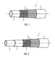
- FIG. 1 shows the perspective view of a four-layer line 1 according to the invention with an inner layer 2, an outer layer 3 and two between the inner layer and the outer layer arranged reinforcing layers 5.
- the heating element 4 is arranged in the form of a heating wire, wherein the heating wire is arranged spirally.
- Other arrangements of the heating wire are conceivable.
- the heating wire extends exclusively along the axial direction of the line.
- a plurality of heating wires may be provided instead of a single.
- the outer layer 3 is made of EPDM with an open cell structure and has a low thermal conductivity of 0.035 W / mK.
- the inner layer 2 is made of EPDM, with particles of high thermal conductivity, for example of aluminum oxide or aluminum nitride, is filled and has a high thermal conductivity of 1 W / mK.
- the reinforcing layers 5 are made of a textile fabric, but there are also metallic tissue conceivable. In addition, in addition to the use of a textile or metallic fabric, the use of just such knitted or knitted or braided is possible.
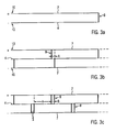
- FIG. 2 shows the perspective view of a five-line line according to the invention 1. Different in contrast to the line according to FIG. 1 is merely the additional use of a subsequent inner to the inner layer 2 barrier layer 6 of a PP-EPDM copolymer, which is why the remaining same features will not be discussed here.
- FIG. 3a shows the schematic, not to scale representation of a first arrangement possibility of current-carrying elements within a line according to the invention.
- the heating element 4 for example in the form of a heat conductor, is electrically connected at one end via a connecting device 8 to one end of the substantially extending along the conduit, not shown, conductor 7, wherein the contacting portion 10 of the heating element to the negative terminal of a voltage source, not shown the contacting portion 10 of the conductor is connected to the positive pole of the voltage source, not shown, and the two adjacent contacting portions are spaced about 1 cm apart.
- FIG. 3b shows the schematic, not to scale representation of a further arrangement possibility of current-carrying elements within a still unassembled and thus not tailored to the length of use line according to the invention.
- the heating element 4 for example in the form of a heat conductor, two conductors 7 are present, which extend substantially along the line 1, not shown.
- the illustration shows only a section again, which can continue in the same way in any length (indicated in the figure by dashed lines).
- the serving as positive conductor conductor is connected to the Kunststoffssensabêt 10 at the positive pole of a voltage source, not shown, while the other serving as negative conductor conductor is connected to the Kunststoffssensabêt 10 at the negative terminal of a voltage source, not shown, wherein the distance of the two contacting portion is about 1 cm.
- the positive conductor is connected to the heating conductor via two connecting devices 8
- the negative conductor is connected to the heating conductor via two connecting devices 8.
- the number of connecting devices arranged between the positive conductor and the heating conductor is correct with the number of connecting devices, which are arranged between negative conductor and heating conductor match. Also not visible on the basis of the detail is the substantially equidistant distance between two adjacent connecting devices which connect the positive conductor to the heating conductor or the negative conductor to the heating conductor, which is for example 10 cm.
- the distances between the adjacent connecting means connecting the positive conductor to the heating conductor and the distances between the adjacent connecting means connecting the negative conductor to the heating conductor are substantially the same. Furthermore, the connecting devices connecting the positive conductor to the heating conductor are offset relative to the connecting devices connecting the negative conductor to the heating conductor, so that in each case two adjacent connecting devices, one of which connects the positive conductor to the heating conductor and the other connects the negative conductor to the heating conductor, with respect to the extension direction of the conductor 7 are spaced.
- the corresponding distance A is for example 2 cm.
- the described arrangement of heating conductor, positive conductor, negative conductor and the connecting devices in this case allows the respective separation of the line at the points where the heating conductors are connected to the positive conductor and the heating conductor with the negative conductor connecting means adjacent to each other.
- the line parts resulting from the cutting then each have a substantially equal length Schuleitermother between the point at which the heating element is connected via the corresponding connection means with the positive conductor, and the point at which the heating element is connected via the corresponding connection means with the negative conductor , on. This results in the separated line parts also substantially the same heating power.
- the unassembled output line can be manufactured very economically, for example, within an extrusion process.
- the introduction of a respective marking can take place during the extrusion process.
- the line take on the additional function of an electrical conductor, so that a passage of electricity through the line is also possible.
- This allows, for example, the electrical Connection of the line with a consumer. An otherwise required own conductor for the electrical supply of the consumer is thus superfluous and can be saved.
- both the plus, as well as the negative conductor allows the electrical supply of the heating element from a (contacting) point of the line, so that a single plug for the power supply of the heating element is sufficient.
- Figure 3c shows the schematic, not to scale representation of a further arrangement possibility of current-carrying elements within a still unassembled and thus not tailored to the length of use line according to the invention.
- the heating element 4 for example in the form of a heat conductor, two conductors 7 are present, which extend over the entire length of the line 1, not shown.
- this representation is only a section again, which can continue in the same way in any length (indicated in the figure by dashed lines).
- each connecting device comprises, in the unseparated state, two connecting conductors 9 which run essentially parallel to one another and have a distance of, for example, 2 cm from each other Figure 3c the positive conductor is connected to the heating conductor via an unseparated and two separate connecting devices 8, while the negative conductor is connected to the heating conductor via two unconnected connecting devices 8.
- two adjacent connecting devices which connect the positive conductor to the heating element and in each case two adjacent connecting devices, which connect the negative conductor to the heating element, are substantially equidistant, for example spaced apart by a length of 10 cm.
- the distance between any two adjacent connection devices which connect the positive conductor to the heating element, with the distance between each two adjacent connection means which connect the negative conductor to the heating conductor substantially coincides.
- Two adjacent connection devices one of which connects the positive conductor and a negative conductor to the heating element, are arranged with respect to the direction of extension of the conductors at a distance A of, for example, 5 cm from each other.
- the unassembled output line can be manufactured very economically, for example, within an extrusion process.
- the introduction of a respective marking can take place during the extrusion process.
Landscapes
- Engineering & Computer Science (AREA)
- General Engineering & Computer Science (AREA)
- Mechanical Engineering (AREA)
- Resistance Heating (AREA)
- Pipe Accessories (AREA)
- Rigid Pipes And Flexible Pipes (AREA)
Claims (14)
- Conduite chauffante (1), en particulier pour le transport de fluides dans des véhicules, comportant au moins une couche interne (2), une couche externe (3) et un élément chauffant (4), dans laquelle la couche interne (2) présente une conductivité thermique plus élevée que la couche externe (3) au moins dans la plage de température de service de la conduite chauffante (1),
caractérisée
en ce que la conduite (1) comporte au moins quatre couches, avec deux couches de renforcement (5) agencées entre les couches interne (2) et externe (3), dans laquelle l'élément chauffant (4) est agencé entre les deux couches de renforcement (5) et est sensiblement en contact avec les couches de renforcement (5), et au moins un conducteur électrique (7) qui s'étend le long de la conduite (1) est pourvu dans la conduite (1). - Conduite chauffante (1) selon la revendication 1, caractérisée en ce que deux conducteurs électriques (7) qui s'étendent essentiellement le long de la conduite (1) sont pourvus.
- Conduite chauffante (1) selon au moins l'une des revendications précédentes, caractérisée en ce que la conduite chauffante (1) peut être connectée à un consommateur électrique.
- Conduite chauffante (1) selon au moins l'une des revendications précédentes, caractérisée en ce que l'élément chauffant (4), par exemple sous forme d'un conducteur chauffant, est connecté électriquement à une extrémité à l'aide d'un dispositif de connexion (8) avec le conducteur électrique (7) qui s'étend le long de la conduite.
- Conduite chauffante (1) selon au moins l'une des revendications précédentes, caractérisée en ce qu'une section de contact (10) du conducteur chauffant (4) peut être connectée au pôle négatif d'une source de tension et en ce qu'une section de contact (10) du conducteur électrique (7) peut être connectée au pôle positif de la source de tension.
- Conduite chauffante (1) selon la revendication 5, caractérisée en ce que les sections de contact voisines (10) sont espacées entre elles d'environ 1 cm.
- Conduite chauffante (1) selon au moins l'une des revendications précédentes, caractérisée en ce qu'un conducteur (7) servant de conducteur positif est connecté à l'aide d'une section de contact (10) au pôle positif d'une source de tension, alors que l'autre conducteur (7) servant de conducteur négatif est connecté à l'aide d'une section de contact (10) au pôle négatif de la source de tension.
- Conduite chauffante (1) selon la revendication 7, caractérisée en ce que le conducteur positif est connecté au conducteur chauffant (4) via deux dispositifs de connexion (8), et en ce que le conducteur négatif est également connecté au conducteur chauffant (4) via deux dispositifs de connexion (8).
- Conduite chauffante (1) selon au moins l'une des revendications précédentes 7 ou 8, caractérisée en ce qu'un certain nombre des dispositifs de connexion (8) qui sont agencés entre le conducteur positif (7) et le conducteur chauffant (4) correspondent au nombre de dispositifs de connexion (8) qui sont agencés entre le conducteur négatif (7) et le conducteur positif (4).
- Conduite chauffante (1) selon au moins l'une des revendications précédentes 7 à 9, caractérisée en ce qu'un espacement essentiellement équidistant entre deux dispositifs de connexion voisins (8) qui connectent le conducteur positif (7) au conducteur chauffant (4) et le conducteur négatif (7) au conducteur chauffant (4) est par exemple de 10 cm.
- Conduite chauffante (1) selon au moins l'une des revendications précédentes 7 à 10, caractérisée en ce que les dispositifs de connexion (8) connectant le conducteur positif au conducteur chauffant (4) sont agencés avec un décalage par rapport aux dispositifs de connexion (8) connectant le conducteur négatif (7) au conducteur chauffant (4).
- Conduite chauffante (1) selon au moins l'une des revendications précédentes 7 à 11, caractérisée en ce que chaque dispositif de connexion (8) comporte, à l'état non déconnecté, deux connecteurs de connexion (9) disposés de manière à être essentiellement parallèles entre eux.
- Conduite chauffante (1) selon au moins l'une des revendications précédentes 7 à 12, caractérisée en ce que la distance entre chaque paire dispositifs de connexion voisins (8) qui connectent le conducteur positif (7) à l'élément chauffant (4) correspond essentiellement à la distance entre chaque paire dispositifs de connexion voisins (8) qui connectent le conducteur négatif (7) au conducteur chauffant (4).
- Conduite chauffante (1) selon au moins l'une des revendications précédentes 7 à 13, caractérisée en ce que grâce à la transmission du conducteur positif ainsi que du conducteur négatif, la conduite (1) prend en charge la fonction additionnelle d'un conducteur électrique, de façon à permettre une conduction de courant via la conduite (1).
Applications Claiming Priority (2)
| Application Number | Priority Date | Filing Date | Title |
|---|---|---|---|
| DE102007014670A DE102007014670A1 (de) | 2007-03-27 | 2007-03-27 | Beheizbare Leitung |
| EP07856427A EP2129885B1 (fr) | 2007-03-27 | 2007-12-06 | Conduite pouvant être chauffée |
Related Parent Applications (1)
| Application Number | Title | Priority Date | Filing Date |
|---|---|---|---|
| EP07856427.5 Division | 2007-12-06 |
Publications (2)
| Publication Number | Publication Date |
|---|---|
| EP2418364A1 EP2418364A1 (fr) | 2012-02-15 |
| EP2418364B1 true EP2418364B1 (fr) | 2013-05-01 |
Family
ID=39166395
Family Applications (2)
| Application Number | Title | Priority Date | Filing Date |
|---|---|---|---|
| EP11008918.2A Not-in-force EP2418364B1 (fr) | 2007-03-27 | 2007-12-06 | Conduite pouvant être chauffée |
| EP07856427A Not-in-force EP2129885B1 (fr) | 2007-03-27 | 2007-12-06 | Conduite pouvant être chauffée |
Family Applications After (1)
| Application Number | Title | Priority Date | Filing Date |
|---|---|---|---|
| EP07856427A Not-in-force EP2129885B1 (fr) | 2007-03-27 | 2007-12-06 | Conduite pouvant être chauffée |
Country Status (5)
| Country | Link |
|---|---|
| EP (2) | EP2418364B1 (fr) |
| AT (1) | ATE544980T1 (fr) |
| DE (1) | DE102007014670A1 (fr) |
| ES (2) | ES2379052T3 (fr) |
| WO (1) | WO2008116492A1 (fr) |
Cited By (1)
| Publication number | Priority date | Publication date | Assignee | Title |
|---|---|---|---|---|
| DE202013103243U1 (de) | 2013-07-19 | 2014-10-20 | Rehau Ag + Co | Medienleitung, insbesondere zum Transport einer Harnstoff-Wasser-Lösung |
Families Citing this family (9)
| Publication number | Priority date | Publication date | Assignee | Title |
|---|---|---|---|---|
| DE102009022995A1 (de) * | 2009-05-28 | 2010-12-02 | Rehau Ag + Co. | Beheizbare Leitung, insbesondere für ein Kraftfahrzeug zum Transport einer Harnstoff-Wasser-Lösung |
| CN101799116B (zh) * | 2010-03-16 | 2013-04-17 | 河北亚大汽车塑料制品有限公司 | 用于输送液体的防冻管路 |
| DE102010032189B4 (de) | 2010-07-23 | 2024-07-25 | Voss Automotive Gmbh | Verfahren zum Herstellen einer beheizbaren Medienleitung und beheizbare Medienleitung, hergestellt nach dem Verfahren |
| DE102011110651A1 (de) * | 2011-08-19 | 2013-02-21 | Voss Automotive Gmbh | Schlauch |
| DE102013223910A1 (de) * | 2013-11-22 | 2015-05-28 | Contitech Ag | Flexibler, mehrschichtiger, beheizbarer Schlauch |
| DE102014115445A1 (de) * | 2014-10-23 | 2016-04-28 | Rehau Ag + Co | Verwendung einer Medienleitung |
| US20190323728A1 (en) * | 2018-04-20 | 2019-10-24 | Tom Richards, Inc. | In-line high purity chemical heater |
| CN110253858B (zh) * | 2019-06-04 | 2024-07-02 | 深圳市源泰医疗器械有限公司 | 一种呼吸管路生产装置及呼吸管路生产方法 |
| WO2021188528A1 (fr) * | 2020-03-18 | 2021-09-23 | Exxonmobil Chemical Patents Inc. | Compositions élastomères thermoplastiques, leur préparation et leur utilisation dans des tuyaux enroulables renforcés par des fibres |
Family Cites Families (13)
| Publication number | Priority date | Publication date | Assignee | Title |
|---|---|---|---|---|
| DE6944664U (de) * | 1969-11-18 | 1970-05-14 | Bode & Co D | Aussen-flammenfester schlauch, der anstelle von festen rohrleitungen verwendung findet. |
| DE3202854C2 (de) * | 1982-01-29 | 1987-01-22 | Pahl'sche Gummi- und Asbest-Gesellschaft "Paguag" GmbH & Co, 4000 Düsseldorf | Elektrisch leitfähige Schlauchleitung |
| EP0312204A3 (fr) * | 1987-10-09 | 1991-07-17 | Raychem Limited | Dispositif de chauffage d'un conduit en polymère conducteur |
| FR2662229B1 (fr) * | 1990-05-17 | 1992-07-31 | Coflexip | Conduite tubulaire flexible comportant des moyens de chauffage incorpores. |
| DE19731178C1 (de) * | 1997-07-10 | 1999-01-28 | Schering Ag | Schlauchleitung mit mindestens einem integrierten elektrischen Leiter |
| JP2000012200A (ja) * | 1998-06-17 | 2000-01-14 | Hitachi Cable Ltd | 加熱用電線 |
| DE19915228A1 (de) * | 1999-04-03 | 2000-10-05 | Continental Teves Ag & Co Ohg | Beheizbarer Druckschlauch für eine Kraftfahrzeug-Bremsvorrichtung |
| DE20103677U1 (de) * | 2001-03-02 | 2001-07-26 | BRUGG Rohrsysteme GmbH, 31515 Wunstorf | Flexibles vorgedämmtes Leitungsrohr |
| DE10152575A1 (de) * | 2001-10-24 | 2003-05-15 | Veritas Ag | Mehrschichtiges Rohr |
| DE10201920B4 (de) | 2002-01-19 | 2018-04-12 | Contitech Schlauch Gmbh | Verfahren zum Verbinden eines Heizleiters eines flexiblen mehrschichtigen Schlauches mit einer elektrischen Anschlussvorrichtung |
| DE10344137A1 (de) | 2003-09-24 | 2005-05-04 | Rasmussen Gmbh | Elektrisch beheizbare Flüssigkeitsleitung |
| EP1931905B1 (fr) * | 2005-09-16 | 2012-08-08 | DYTECH - Dynamic Fluid Technologies S.p.A. | Systeme de tuyau multicouche pour l'acheminement et le chauffage de fluide |
| DE102005044846A1 (de) * | 2005-09-20 | 2007-03-29 | Dbk David + Baader Gmbh | Elektrische Heizvorrichtung, beheizbarer Schlauch und Herstellungsverfahren derselben |
-
2007
- 2007-03-27 DE DE102007014670A patent/DE102007014670A1/de not_active Withdrawn
- 2007-12-06 ES ES07856427T patent/ES2379052T3/es active Active
- 2007-12-06 AT AT07856427T patent/ATE544980T1/de active
- 2007-12-06 EP EP11008918.2A patent/EP2418364B1/fr not_active Not-in-force
- 2007-12-06 WO PCT/EP2007/010622 patent/WO2008116492A1/fr active Application Filing
- 2007-12-06 ES ES11008918T patent/ES2411959T3/es active Active
- 2007-12-06 EP EP07856427A patent/EP2129885B1/fr not_active Not-in-force
Cited By (2)
| Publication number | Priority date | Publication date | Assignee | Title |
|---|---|---|---|---|
| DE202013103243U1 (de) | 2013-07-19 | 2014-10-20 | Rehau Ag + Co | Medienleitung, insbesondere zum Transport einer Harnstoff-Wasser-Lösung |
| DE102014108779A1 (de) | 2013-07-19 | 2015-01-22 | Rehau Ag + Co. | Medienleitung, insbesondere zum Transport einer Harnstoff-Wasser-Lösung |
Also Published As
| Publication number | Publication date |
|---|---|
| EP2129885B1 (fr) | 2012-02-08 |
| WO2008116492A1 (fr) | 2008-10-02 |
| ES2379052T3 (es) | 2012-04-20 |
| ATE544980T1 (de) | 2012-02-15 |
| EP2129885A1 (fr) | 2009-12-09 |
| DE102007014670A1 (de) | 2008-10-02 |
| EP2418364A1 (fr) | 2012-02-15 |
| ES2411959T3 (es) | 2013-07-09 |
Similar Documents
| Publication | Publication Date | Title |
|---|---|---|
| EP2418364B1 (fr) | Conduite pouvant être chauffée | |
| EP2699414B1 (fr) | Conduite de milieux multicouche pouvant être chauffée électriquement | |
| EP2596274B1 (fr) | Conduite chauffable pour fluides et méthode de sa production | |
| EP2641006B1 (fr) | Conduite de fluides confectionnée à chauffage électrique et procédé de fabrication de ladite conduite | |
| EP2167860B1 (fr) | Dispositif de raccord pour des tuyaux qui conduisent des milieux et qui peuvent être chauffés électriquement | |
| EP2596275B1 (fr) | Conduite chauffable pour fluides | |
| DE102005037183B3 (de) | Beheizbare Fluidleitung | |
| EP2766652B1 (fr) | Conduite de fluide pouvant être chauffée comprenant au moins une conduite de fluide présentant deux raccords de conduite | |
| EP2788692B1 (fr) | Conduite à fluide confectionnée, sous forme d'une conduite à fluide comportant au moins deux éléments de chauffe placés sur sa face externe, et procédé de production de ladite conduite | |
| DE202013101624U1 (de) | Beheizbarer Stromabnehmer zum Herstellen von elektrischem Kontakt zwischen einer stromführenden Leitung und einem Elektrofahrzeug, sowie Heizeinrichtung zur Verwendung in diesem Stromabnehmer | |
| DE102013000588A1 (de) | Konfektionierte beheizbare Medienleitung, Verwendung einer solchen sowie Verfahren zum Herstellen einer solchen | |
| EP3092433B1 (fr) | Conduite de fluide chauffante surmoulée et procédé de fabrication de cette dernière | |
| DE202008007392U1 (de) | Fluidleitung und Leitungsverbinder zum Führen und Beheizen eines Mediums | |
| DE202007019332U1 (de) | Beheizbare Leitung | |
| EP3234434B1 (fr) | Conduite de fluide chauffante et procédé pour fabriquer une conduite de fluide chauffante | |
| WO2017167452A2 (fr) | Conduite de fluide chauffante assemblée ainsi qu'élément chauffant assemblé pour utilisation dans ladite conduite | |
| WO2010097163A1 (fr) | Dispositif de chauffage électrique | |
| DE202004019660U1 (de) | Vorrichtung zur Aufnahme eines Bündels von elektrischen Leitungen |
Legal Events
| Date | Code | Title | Description |
|---|---|---|---|
| AC | Divisional application: reference to earlier application |
Ref document number: 2129885 Country of ref document: EP Kind code of ref document: P |
|
| AK | Designated contracting states |
Kind code of ref document: A1 Designated state(s): AT BE BG CH CY CZ DE DK EE ES FI FR GB GR HU IE IS IT LI LT LU LV MC MT NL PL PT RO SE SI SK TR |
|
| PUAI | Public reference made under article 153(3) epc to a published international application that has entered the european phase |
Free format text: ORIGINAL CODE: 0009012 |
|
| 17P | Request for examination filed |
Effective date: 20120720 |
|
| RIC1 | Information provided on ipc code assigned before grant |
Ipc: F16L 11/127 20060101ALI20121017BHEP Ipc: F16L 53/00 20060101ALI20121017BHEP Ipc: F01N 3/20 20060101AFI20121017BHEP Ipc: H05B 3/58 20060101ALI20121017BHEP Ipc: F16L 11/08 20060101ALI20121017BHEP |
|
| GRAP | Despatch of communication of intention to grant a patent |
Free format text: ORIGINAL CODE: EPIDOSNIGR1 |
|
| GRAS | Grant fee paid |
Free format text: ORIGINAL CODE: EPIDOSNIGR3 |
|
| GRAA | (expected) grant |
Free format text: ORIGINAL CODE: 0009210 |
|
| AC | Divisional application: reference to earlier application |
Ref document number: 2129885 Country of ref document: EP Kind code of ref document: P |
|
| AK | Designated contracting states |
Kind code of ref document: B1 Designated state(s): AT BE BG CH CY CZ DE DK EE ES FI FR GB GR HU IE IS IT LI LT LU LV MC MT NL PL PT RO SE SI SK TR |
|
| REG | Reference to a national code |
Ref country code: GB Ref legal event code: FG4D Free format text: NOT ENGLISH |
|
| REG | Reference to a national code |
Ref country code: AT Ref legal event code: REF Ref document number: 610093 Country of ref document: AT Kind code of ref document: T Effective date: 20130515 Ref country code: CH Ref legal event code: EP |
|
| REG | Reference to a national code |
Ref country code: IE Ref legal event code: FG4D Free format text: LANGUAGE OF EP DOCUMENT: GERMAN |
|
| REG | Reference to a national code |
Ref country code: DE Ref legal event code: R096 Ref document number: 502007011713 Country of ref document: DE Effective date: 20130627 |
|
| REG | Reference to a national code |
Ref country code: ES Ref legal event code: FG2A Ref document number: 2411959 Country of ref document: ES Kind code of ref document: T3 Effective date: 20130709 |
|
| REG | Reference to a national code |
Ref country code: NL Ref legal event code: VDEP Effective date: 20130501 |
|
| REG | Reference to a national code |
Ref country code: LT Ref legal event code: MG4D |
|
| PG25 | Lapsed in a contracting state [announced via postgrant information from national office to epo] |
Ref country code: FI Free format text: LAPSE BECAUSE OF FAILURE TO SUBMIT A TRANSLATION OF THE DESCRIPTION OR TO PAY THE FEE WITHIN THE PRESCRIBED TIME-LIMIT Effective date: 20130501 Ref country code: PT Free format text: LAPSE BECAUSE OF FAILURE TO SUBMIT A TRANSLATION OF THE DESCRIPTION OR TO PAY THE FEE WITHIN THE PRESCRIBED TIME-LIMIT Effective date: 20130902 Ref country code: SI Free format text: LAPSE BECAUSE OF FAILURE TO SUBMIT A TRANSLATION OF THE DESCRIPTION OR TO PAY THE FEE WITHIN THE PRESCRIBED TIME-LIMIT Effective date: 20130501 Ref country code: GR Free format text: LAPSE BECAUSE OF FAILURE TO SUBMIT A TRANSLATION OF THE DESCRIPTION OR TO PAY THE FEE WITHIN THE PRESCRIBED TIME-LIMIT Effective date: 20130802 Ref country code: SE Free format text: LAPSE BECAUSE OF FAILURE TO SUBMIT A TRANSLATION OF THE DESCRIPTION OR TO PAY THE FEE WITHIN THE PRESCRIBED TIME-LIMIT Effective date: 20130501 Ref country code: LT Free format text: LAPSE BECAUSE OF FAILURE TO SUBMIT A TRANSLATION OF THE DESCRIPTION OR TO PAY THE FEE WITHIN THE PRESCRIBED TIME-LIMIT Effective date: 20130501 Ref country code: IS Free format text: LAPSE BECAUSE OF FAILURE TO SUBMIT A TRANSLATION OF THE DESCRIPTION OR TO PAY THE FEE WITHIN THE PRESCRIBED TIME-LIMIT Effective date: 20130901 |
|
| PG25 | Lapsed in a contracting state [announced via postgrant information from national office to epo] |
Ref country code: PL Free format text: LAPSE BECAUSE OF FAILURE TO SUBMIT A TRANSLATION OF THE DESCRIPTION OR TO PAY THE FEE WITHIN THE PRESCRIBED TIME-LIMIT Effective date: 20130501 Ref country code: BG Free format text: LAPSE BECAUSE OF FAILURE TO SUBMIT A TRANSLATION OF THE DESCRIPTION OR TO PAY THE FEE WITHIN THE PRESCRIBED TIME-LIMIT Effective date: 20130801 Ref country code: CY Free format text: LAPSE BECAUSE OF FAILURE TO SUBMIT A TRANSLATION OF THE DESCRIPTION OR TO PAY THE FEE WITHIN THE PRESCRIBED TIME-LIMIT Effective date: 20130501 |
|
| PG25 | Lapsed in a contracting state [announced via postgrant information from national office to epo] |
Ref country code: LV Free format text: LAPSE BECAUSE OF FAILURE TO SUBMIT A TRANSLATION OF THE DESCRIPTION OR TO PAY THE FEE WITHIN THE PRESCRIBED TIME-LIMIT Effective date: 20130501 |
|
| PG25 | Lapsed in a contracting state [announced via postgrant information from national office to epo] |
Ref country code: SK Free format text: LAPSE BECAUSE OF FAILURE TO SUBMIT A TRANSLATION OF THE DESCRIPTION OR TO PAY THE FEE WITHIN THE PRESCRIBED TIME-LIMIT Effective date: 20130501 Ref country code: CZ Free format text: LAPSE BECAUSE OF FAILURE TO SUBMIT A TRANSLATION OF THE DESCRIPTION OR TO PAY THE FEE WITHIN THE PRESCRIBED TIME-LIMIT Effective date: 20130501 Ref country code: DK Free format text: LAPSE BECAUSE OF FAILURE TO SUBMIT A TRANSLATION OF THE DESCRIPTION OR TO PAY THE FEE WITHIN THE PRESCRIBED TIME-LIMIT Effective date: 20130501 Ref country code: EE Free format text: LAPSE BECAUSE OF FAILURE TO SUBMIT A TRANSLATION OF THE DESCRIPTION OR TO PAY THE FEE WITHIN THE PRESCRIBED TIME-LIMIT Effective date: 20130501 |
|
| PG25 | Lapsed in a contracting state [announced via postgrant information from national office to epo] |
Ref country code: IT Free format text: LAPSE BECAUSE OF FAILURE TO SUBMIT A TRANSLATION OF THE DESCRIPTION OR TO PAY THE FEE WITHIN THE PRESCRIBED TIME-LIMIT Effective date: 20130501 Ref country code: NL Free format text: LAPSE BECAUSE OF FAILURE TO SUBMIT A TRANSLATION OF THE DESCRIPTION OR TO PAY THE FEE WITHIN THE PRESCRIBED TIME-LIMIT Effective date: 20130501 Ref country code: RO Free format text: LAPSE BECAUSE OF FAILURE TO SUBMIT A TRANSLATION OF THE DESCRIPTION OR TO PAY THE FEE WITHIN THE PRESCRIBED TIME-LIMIT Effective date: 20130501 |
|
| PLBE | No opposition filed within time limit |
Free format text: ORIGINAL CODE: 0009261 |
|
| STAA | Information on the status of an ep patent application or granted ep patent |
Free format text: STATUS: NO OPPOSITION FILED WITHIN TIME LIMIT |
|
| 26N | No opposition filed |
Effective date: 20140204 |
|
| REG | Reference to a national code |
Ref country code: DE Ref legal event code: R097 Ref document number: 502007011713 Country of ref document: DE Effective date: 20140204 |
|
| BERE | Be: lapsed |
Owner name: VERITAS A.G. Effective date: 20131231 |
|
| REG | Reference to a national code |
Ref country code: DE Ref legal event code: R119 Ref document number: 502007011713 Country of ref document: DE |
|
| REG | Reference to a national code |
Ref country code: CH Ref legal event code: PL |
|
| GBPC | Gb: european patent ceased through non-payment of renewal fee |
Effective date: 20131206 |
|
| PG25 | Lapsed in a contracting state [announced via postgrant information from national office to epo] |
Ref country code: LU Free format text: LAPSE BECAUSE OF FAILURE TO SUBMIT A TRANSLATION OF THE DESCRIPTION OR TO PAY THE FEE WITHIN THE PRESCRIBED TIME-LIMIT Effective date: 20131206 |
|
| REG | Reference to a national code |
Ref country code: IE Ref legal event code: MM4A |
|
| REG | Reference to a national code |
Ref country code: DE Ref legal event code: R119 Ref document number: 502007011713 Country of ref document: DE Effective date: 20140701 |
|
| REG | Reference to a national code |
Ref country code: FR Ref legal event code: ST Effective date: 20140829 |
|
| PG25 | Lapsed in a contracting state [announced via postgrant information from national office to epo] |
Ref country code: CH Free format text: LAPSE BECAUSE OF NON-PAYMENT OF DUE FEES Effective date: 20131231 Ref country code: DE Free format text: LAPSE BECAUSE OF NON-PAYMENT OF DUE FEES Effective date: 20140701 Ref country code: BE Free format text: LAPSE BECAUSE OF NON-PAYMENT OF DUE FEES Effective date: 20131231 Ref country code: IE Free format text: LAPSE BECAUSE OF NON-PAYMENT OF DUE FEES Effective date: 20131206 Ref country code: LI Free format text: LAPSE BECAUSE OF NON-PAYMENT OF DUE FEES Effective date: 20131231 |
|
| PG25 | Lapsed in a contracting state [announced via postgrant information from national office to epo] |
Ref country code: FR Free format text: LAPSE BECAUSE OF NON-PAYMENT OF DUE FEES Effective date: 20131231 Ref country code: GB Free format text: LAPSE BECAUSE OF NON-PAYMENT OF DUE FEES Effective date: 20131206 |
|
| REG | Reference to a national code |
Ref country code: AT Ref legal event code: MM01 Ref document number: 610093 Country of ref document: AT Kind code of ref document: T Effective date: 20131206 |
|
| PG25 | Lapsed in a contracting state [announced via postgrant information from national office to epo] |
Ref country code: MC Free format text: LAPSE BECAUSE OF FAILURE TO SUBMIT A TRANSLATION OF THE DESCRIPTION OR TO PAY THE FEE WITHIN THE PRESCRIBED TIME-LIMIT Effective date: 20130501 |
|
| PG25 | Lapsed in a contracting state [announced via postgrant information from national office to epo] |
Ref country code: AT Free format text: LAPSE BECAUSE OF NON-PAYMENT OF DUE FEES Effective date: 20131206 |
|
| PG25 | Lapsed in a contracting state [announced via postgrant information from national office to epo] |
Ref country code: TR Free format text: LAPSE BECAUSE OF FAILURE TO SUBMIT A TRANSLATION OF THE DESCRIPTION OR TO PAY THE FEE WITHIN THE PRESCRIBED TIME-LIMIT Effective date: 20130501 |
|
| REG | Reference to a national code |
Ref country code: ES Ref legal event code: FD2A Effective date: 20150715 |
|
| PG25 | Lapsed in a contracting state [announced via postgrant information from national office to epo] |
Ref country code: HU Free format text: LAPSE BECAUSE OF FAILURE TO SUBMIT A TRANSLATION OF THE DESCRIPTION OR TO PAY THE FEE WITHIN THE PRESCRIBED TIME-LIMIT; INVALID AB INITIO Effective date: 20071206 Ref country code: ES Free format text: LAPSE BECAUSE OF NON-PAYMENT OF DUE FEES Effective date: 20131207 |
|
| PG25 | Lapsed in a contracting state [announced via postgrant information from national office to epo] |
Ref country code: MT Free format text: LAPSE BECAUSE OF FAILURE TO SUBMIT A TRANSLATION OF THE DESCRIPTION OR TO PAY THE FEE WITHIN THE PRESCRIBED TIME-LIMIT Effective date: 20130501 |