EP2418364B1 - Heatable conduit - Google Patents
Heatable conduit Download PDFInfo
- Publication number
- EP2418364B1 EP2418364B1 EP11008918.2A EP11008918A EP2418364B1 EP 2418364 B1 EP2418364 B1 EP 2418364B1 EP 11008918 A EP11008918 A EP 11008918A EP 2418364 B1 EP2418364 B1 EP 2418364B1
- Authority
- EP
- European Patent Office
- Prior art keywords
- conductor
- conduit
- heating
- heatable
- connecting devices
- Prior art date
- Legal status (The legal status is an assumption and is not a legal conclusion. Google has not performed a legal analysis and makes no representation as to the accuracy of the status listed.)
- Not-in-force
Links
Images
Classifications
-
- H—ELECTRICITY
- H05—ELECTRIC TECHNIQUES NOT OTHERWISE PROVIDED FOR
- H05B—ELECTRIC HEATING; ELECTRIC LIGHT SOURCES NOT OTHERWISE PROVIDED FOR; CIRCUIT ARRANGEMENTS FOR ELECTRIC LIGHT SOURCES, IN GENERAL
- H05B3/00—Ohmic-resistance heating
- H05B3/40—Heating elements having the shape of rods or tubes
- H05B3/54—Heating elements having the shape of rods or tubes flexible
- H05B3/58—Heating hoses; Heating collars
-
- F—MECHANICAL ENGINEERING; LIGHTING; HEATING; WEAPONS; BLASTING
- F16—ENGINEERING ELEMENTS AND UNITS; GENERAL MEASURES FOR PRODUCING AND MAINTAINING EFFECTIVE FUNCTIONING OF MACHINES OR INSTALLATIONS; THERMAL INSULATION IN GENERAL
- F16L—PIPES; JOINTS OR FITTINGS FOR PIPES; SUPPORTS FOR PIPES, CABLES OR PROTECTIVE TUBING; MEANS FOR THERMAL INSULATION IN GENERAL
- F16L11/00—Hoses, i.e. flexible pipes
- F16L11/04—Hoses, i.e. flexible pipes made of rubber or flexible plastics
- F16L11/08—Hoses, i.e. flexible pipes made of rubber or flexible plastics with reinforcements embedded in the wall
- F16L11/085—Hoses, i.e. flexible pipes made of rubber or flexible plastics with reinforcements embedded in the wall comprising one or more braided layers
- F16L11/086—Hoses, i.e. flexible pipes made of rubber or flexible plastics with reinforcements embedded in the wall comprising one or more braided layers two layers
-
- F—MECHANICAL ENGINEERING; LIGHTING; HEATING; WEAPONS; BLASTING
- F16—ENGINEERING ELEMENTS AND UNITS; GENERAL MEASURES FOR PRODUCING AND MAINTAINING EFFECTIVE FUNCTIONING OF MACHINES OR INSTALLATIONS; THERMAL INSULATION IN GENERAL
- F16L—PIPES; JOINTS OR FITTINGS FOR PIPES; SUPPORTS FOR PIPES, CABLES OR PROTECTIVE TUBING; MEANS FOR THERMAL INSULATION IN GENERAL
- F16L11/00—Hoses, i.e. flexible pipes
- F16L11/04—Hoses, i.e. flexible pipes made of rubber or flexible plastics
- F16L11/12—Hoses, i.e. flexible pipes made of rubber or flexible plastics with arrangements for particular purposes, e.g. specially profiled, with protecting layer, heated, electrically conducting
- F16L11/127—Hoses, i.e. flexible pipes made of rubber or flexible plastics with arrangements for particular purposes, e.g. specially profiled, with protecting layer, heated, electrically conducting electrically conducting
-
- F—MECHANICAL ENGINEERING; LIGHTING; HEATING; WEAPONS; BLASTING
- F16—ENGINEERING ELEMENTS AND UNITS; GENERAL MEASURES FOR PRODUCING AND MAINTAINING EFFECTIVE FUNCTIONING OF MACHINES OR INSTALLATIONS; THERMAL INSULATION IN GENERAL
- F16L—PIPES; JOINTS OR FITTINGS FOR PIPES; SUPPORTS FOR PIPES, CABLES OR PROTECTIVE TUBING; MEANS FOR THERMAL INSULATION IN GENERAL
- F16L53/00—Heating of pipes or pipe systems; Cooling of pipes or pipe systems
- F16L53/30—Heating of pipes or pipe systems
- F16L53/35—Ohmic-resistance heating
- F16L53/38—Ohmic-resistance heating using elongate electric heating elements, e.g. wires or ribbons
-
- F—MECHANICAL ENGINEERING; LIGHTING; HEATING; WEAPONS; BLASTING
- F01—MACHINES OR ENGINES IN GENERAL; ENGINE PLANTS IN GENERAL; STEAM ENGINES
- F01N—GAS-FLOW SILENCERS OR EXHAUST APPARATUS FOR MACHINES OR ENGINES IN GENERAL; GAS-FLOW SILENCERS OR EXHAUST APPARATUS FOR INTERNAL COMBUSTION ENGINES
- F01N2610/00—Adding substances to exhaust gases
- F01N2610/02—Adding substances to exhaust gases the substance being ammonia or urea
-
- F—MECHANICAL ENGINEERING; LIGHTING; HEATING; WEAPONS; BLASTING
- F01—MACHINES OR ENGINES IN GENERAL; ENGINE PLANTS IN GENERAL; STEAM ENGINES
- F01N—GAS-FLOW SILENCERS OR EXHAUST APPARATUS FOR MACHINES OR ENGINES IN GENERAL; GAS-FLOW SILENCERS OR EXHAUST APPARATUS FOR INTERNAL COMBUSTION ENGINES
- F01N2610/00—Adding substances to exhaust gases
- F01N2610/10—Adding substances to exhaust gases the substance being heated, e.g. by heating tank or supply line of the added substance
-
- F—MECHANICAL ENGINEERING; LIGHTING; HEATING; WEAPONS; BLASTING
- F01—MACHINES OR ENGINES IN GENERAL; ENGINE PLANTS IN GENERAL; STEAM ENGINES
- F01N—GAS-FLOW SILENCERS OR EXHAUST APPARATUS FOR MACHINES OR ENGINES IN GENERAL; GAS-FLOW SILENCERS OR EXHAUST APPARATUS FOR INTERNAL COMBUSTION ENGINES
- F01N2610/00—Adding substances to exhaust gases
- F01N2610/14—Arrangements for the supply of substances, e.g. conduits
- F01N2610/1486—Means to prevent the substance from freezing
-
- F—MECHANICAL ENGINEERING; LIGHTING; HEATING; WEAPONS; BLASTING
- F16—ENGINEERING ELEMENTS AND UNITS; GENERAL MEASURES FOR PRODUCING AND MAINTAINING EFFECTIVE FUNCTIONING OF MACHINES OR INSTALLATIONS; THERMAL INSULATION IN GENERAL
- F16L—PIPES; JOINTS OR FITTINGS FOR PIPES; SUPPORTS FOR PIPES, CABLES OR PROTECTIVE TUBING; MEANS FOR THERMAL INSULATION IN GENERAL
- F16L11/00—Hoses, i.e. flexible pipes
- F16L11/04—Hoses, i.e. flexible pipes made of rubber or flexible plastics
- F16L2011/047—Hoses, i.e. flexible pipes made of rubber or flexible plastics with a diffusion barrier layer
Landscapes
- Engineering & Computer Science (AREA)
- General Engineering & Computer Science (AREA)
- Mechanical Engineering (AREA)
- Resistance Heating (AREA)
- Pipe Accessories (AREA)
- Rigid Pipes And Flexible Pipes (AREA)
Abstract
Description
Die vorliegende Erfindung betrifft eine beheizbare Leitung, insbesondere zum Transport von Flüssigkeiten in Fahrzeugen gemäß dem Oberbegriff von Anspruch 1.The present invention relates to a heatable line, in particular for the transport of liquids in vehicles according to the preamble of
Eine derartige beheizbare Flüssigkeitsleitung ist beispielsweise aus der
Solche beheizbaren Leitungen werden z.B. für den Transport von Harnstoffen wie etwa dem so genannten "AdBlue" für dieselbetriebene Fahrzeuge eingesetzt, um hier ein Einfrieren bei entsprechend niedrigen Umgebungstemperaturen zu vermeiden. Darüber hinaus können diese Leitungen auch zum Transport von Dieselkraftstoff, Kühl- bzw. Waschwasser oder Bremsöl verwendet werden. Zusätzlich zu dem gewünschten Effekt der Verhinderung des Einfrierens bzw. der Viskositätserhöhung der jeweiligen Flüssigkeit können die beheizbaren Leitungen im Falle des Dieselkraftstoffs dessen Vorwärmung dienen, was beispielsweise für eine bessere Zündfähigkeit bzw. Verbrennung des Diesels sorgt.Such heatable lines are e.g. used for the transport of ureas such as the so-called "AdBlue" for diesel-powered vehicles in order to avoid freezing at correspondingly low ambient temperatures. In addition, these lines can also be used to transport diesel fuel, cooling or washing water or brake oil. In addition to the desired effect of preventing the freezing or the viscosity increase of the respective liquid, the heatable lines can serve in the case of the diesel fuel whose preheating, which provides, for example, a better ignitability or combustion of the diesel.
Aus der
Zum Stand der Technik zählt auch die
Die Druckschrift
Nachteilig ist bei den zuvor beschriebenen Heizvorrichtungen, dass der Heizdraht schwer von außen kontaktierbar ist, nachdem die Konfektionierung der Leitungslänge erfolgt ist.A disadvantage of the heating devices described above, that the heating wire is difficult to contact from the outside, after the assembly of the cable length is done.
Es ist daher Aufgabe der Erfindung, eine beheizbare Leitung bereitzustellen, bei der eine Kontaktierung des Heizdrahtes deutlich einfacher realisierbar ist.It is therefore an object of the invention to provide a heatable line, in which a contacting of the heating wire is much easier to implement.
Diese Aufgabe wird erfindungsgemäß durch den Gegenstand des Anspruchs 1 gelöst. Weitere Ausgestaltungen der Erfindung sind in den abhängigen Ansprüchen aufgeführt.This object is achieved by the subject matter of
Der Einsatztemperaturbereich beschreibt hierbei den Umgebungs-Temperaturbereich, innerhalb dessen der Betrieb eines Fahrzeuges normalerweise vorgesehen ist, d.h. etwa zwischen -40°C und +70°C.The operating temperature range here describes the ambient temperature range within which the operation of a vehicle is normally provided, i. between about -40 ° C and + 70 ° C.
Hinsichtlich der Bezeichnungen "innere Lage" und "äußere Lage" wird darauf hingewiesen, dass hierdurch keine absoluten geometrischen (Positions-)Lagen beschrieben sind, so dass sich beispielsweise an die innere Lage innen eine weitere, z.B. innerste Lage, und an die äußere Lage außen eine weitere, z.B. eine Decklage, anschließen kann.With regard to the terms " inner layer " and " outer layer ", it is pointed out that this does not describe any absolute geometric (positional) layers, so that, for example, the inner layer has a further, eg innermost, layer and the outer layer outside another, such as a cover layer, can connect.
Es kann von Vorteil sein, dass die Wärmeleitfähigkeit der inneren Lage größer als 0,75 W/mK ist und vorzugsweise zwischen 0,8 und 1,0 W/mK liegt, und die Wärmeleitfähigkeit der äußeren Lage kleiner als 0,05 W/mK ist und vorzugsweise zwischen 0,01 und 0,04 W/mK liegt. Bei besagten Werten der Wärmeleitfähigkeit für die innere und die äußere Lage kommt es zu einer sehr effektiven Wärmeleitung in Richtung der durch die Leitung transportierten Flüssigkeit und nur zu einer geringen Wärmeleitung in Richtung der Umgebung der Leitung.It may be advantageous that the thermal conductivity of the inner layer is greater than 0.75 W / mK, and preferably between 0.8 and 1.0 W / mK, and the outer layer thermal conductivity is less than 0.05 W / mK and is preferably between 0.01 and 0.04 W / mK. At said values of the thermal conductivity for the inner and the outer layer, there is a very effective heat conduction in the direction of the transported liquid through the line and only a small heat conduction in the direction of the environment of the line.
Ebenso kann es von Vorteil sein, dass die innere und/oder die äußere Lage ein polymeres Material, vorzugsweise einen elastomeren Werkstoff, aufweisen bzw. aufweist. Diese Materialien lassen sing generell gut chemikalien- bzw. medienbeständig, vergleichsweise günstig und zudem relativ einfach verarbeitbar bzw. formbar.Likewise, it may be advantageous for the inner and / or the outer layer to comprise or have a polymeric material, preferably an elastomeric material. These materials generally give good chemical and / or media resistance, comparatively low cost, and are relatively easy to process or mold.
Zudem kann es von Vorteil sein, dass die innere und die äußere Lage den Werkstoff EPDM aufweisen. Dieser Werkstoff zeichnet sich insbesondere durch eine gute Chemikalien- bzw. Medienbeständigkeit, vor allem in Hinblick auf Harnstoff, aus. Darüber hinaus besitzt er eine hohe Wetter- und Feuchtigkeitsbeständigkeit, eine hohe Ozonresistenz und eine sehr gute thermische Beständigkeit.In addition, it may be advantageous that the inner and the outer layer have the material EPDM. This material is characterized in particular by a good resistance to chemicals or media, especially with regard to urea. In addition, it has a high weather and moisture resistance, a high ozone resistance and a very good thermal resistance.
Darüber hinaus kann es von Vorteil sein, dass die äußere Lage ein eine offene Zellstruktur aufweisendes EPDM aufweist und vorzugsweise aus diesem besteht. Durch die offene Zellstruktur ergibt sich eine sehr geringe Wärmeleitfähigkeit, so dass eine Wärmeleitung nach außen, d.h. zur Umgebung der beheizbaren Leitung, nur schwer stattfinden kann.In addition, it may be advantageous that the outer layer has an EPDM having an open cell structure and preferably consists of this. Due to the open cell structure results in a very low thermal conductivity, so that a heat conduction to the outside, i. to the environment of the heated pipe, difficult to take place.
In einer bevorzugten Ausführungsform weist die innere Lage ein mit Partikeln hoher Wärmeleitfähigkeit gefülltes EPDM auf und besteht vorzugsweise aus diesem. Durch die Füllung mit Partikeln, welche eine hohe Wärmeleitfähigkeit aufweisen, ergibt sich insgesamt eine hohe Wärmeleitfähigkeit des gefüllten EPDM-Systems, so dass die Wärmeleitung nach innen, d.h. in Richtung der Flüssigkeit, sehr effektiv ist.In a preferred embodiment, the inner layer has an EPDM filled with particles of high thermal conductivity, and preferably consists of this. By filling with particles which have a high thermal conductivity, the overall result is a high thermal conductivity of the filled EPDM system, so that the heat conduction to the inside, i. in the direction of the liquid, is very effective.
Gemäß der Erfindung ergibt sich eine besonders druckfeste Leitung, wobei das Heizelement zwischen den beiden Verstärkungslagen gut geschützt ist. Im Falle der Verwendung eines Heizdrahtes als Heizelement ist hierbei insbesondere die entsprechende Drahtisolierung bei der Verarbeitung der Leitung geschützt, so dass beispielsweise eine Verletzung des Heizdrahtes bzw. der Drahtisolierung durch das Extrusionswerkzeug während der Extrusion der äußeren Lage, z.B. der Deckenlage, vermieden werden kann. Zudem bietet die Anordnung des Heizelements zwischen den beiden Verstärkungslagen Vorteile hinsichtlich dessen elektrischer Kontaktierung, beispielsweise mit einem Kontaktstecker. Das Heizelement hat bei dieser Anordnung im Wesentlichen Kontakt mit den Verstärkungslagen und kann dadurch relativ leicht bei äußerem Kraftangriff bewegt bzw. in seiner Lage verändert werden. So kann beispielsweise bei Verwendung eines Heizdrahtes als Heizelement dieser zwecks Kontaktierung auf einfache und mühelose Weise am gegebenenfalls abgelängten Ende der Leitung herausgezogen werden.According to the invention results in a particularly pressure-resistant line, wherein the heating element is well protected between the two reinforcing layers. In the case of using a heating wire as a heating element in this case, in particular, the corresponding wire insulation is protected in the processing of the line, so that, for example, a violation of the heating wire or the wire insulation by the extrusion die during the extrusion of the outer layer, e.g. the ceiling position, can be avoided. In addition, the arrangement of the heating element between the two reinforcing layers offers advantages in terms of its electrical contacting, for example with a contact plug. The heating element in this arrangement has substantially contact with the reinforcing layers and can thereby be relatively easily moved or changed in position with external force attack. Thus, for example, when using a heating wire as a heating element this for the purpose of contacting in a simple and effortless manner at the optionally cut end of the line can be pulled out.
Diese beschriebene einfache Art der Kontaktierung des Heizelements steht im Gegensatz zu der aufwendigen und nachteiligen Kontaktierungsmethode gemäß Druckschrift
Vorzugsweise ist das Heizelement zumindest ein Heizdraht. Solch ein Heizelement ist relativ günstig und lässt sich vergleichsweise verarbeiten bzw. in die Leitung während deren Herstellung einfügen.Preferably, the heating element is at least one heating wire. Such a heating element is relatively inexpensive and can be comparatively processed or inserted into the conduit during its manufacture.
Es kann von Vorteil sein, dass sich das Heizelement zumindest entlang der Axialrichtung der Leitung erstreckt. Diese Art der Anordnung lässt sich besonders einfach realisieren.It may be advantageous for the heating element to extend at least along the axial direction of the line. This type of arrangement is particularly easy to implement.
Es kann ebenso von Vorteil sein, dass sich das Heizelement sowohl entlang der Axialrichtung, als auch der Radialrichtung der Leitung erstreckt. Beispielsweise ist es möglich, dass das Heizelement, z.B. in Form eines Heizdrahtes, innerhalb der Leitung spiralförmig angeordnet ist. Somit kann die Heizleistung pro Längenabschnitt der Leitung erhöht bzw. durch die Steigung gezielt angepasst werden.It may also be advantageous that the heating element extends both along the axial direction and the radial direction of the conduit. For example, it is possible that the heating element, e.g. in the form of a heating wire, is arranged spirally within the conduit. Thus, the heating power per length of the line can be increased or adjusted by the slope targeted.
Die Merkmale und Vorteile der Erfindung werden eingehender in der nachstehenden Beschreibung dargelegt, wobei auf die beigefügten Zeichnungen Bezug genommen wird, auf denen folgendes dargestellt ist:
- Fig. 1:
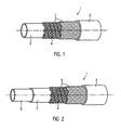
- perspektivische Ansicht einer erfindungsgemäßen beheizbaren Leitung mit 4 Lagen
- Fig. 2:
- perspektivische Ansicht einer erfindungsgemäßen beheizbaren Leitung mit 5 Lagen
- Fig. 3a:
- Schematische Darstellung einer Anordnungsmöglichkeit von stromführenden Elementen innerhalb einer erfindungsgemäßen Leitung
- Fig. 3b:
- Schematische Darstellung einer weiteren Anordnungsmöglichkeit von stromführenden Elementen innerhalb einer unkonfektionierten erfindungsgemäßen Leitung
- Fig. 3c:
- Schematische Darstellung einer weiteren Anordnungsmöglichkeit von stromführenden Elementen innerhalb einer unkonfektionierten erfindungsgemäßen Leitung.
- Fig. 1:
- Perspective view of a heated line according to the invention with 4 layers
- Fig. 2:
- Perspective view of a heatable line according to the invention with 5 layers
- Fig. 3a:
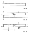
- Schematic representation of a possible arrangement of current-carrying elements within a line according to the invention
- 3b:
- Schematic representation of a further arrangement possibility of current-carrying elements within a non-assembled line according to the invention
- 3c:
- Schematic representation of a further arrangement possibility of current-carrying elements within a non-assembled line according to the invention.
Die nicht maßstäbliche
Die nicht maßstäbliche
Der als Plusleiter dienende Leiter ist mit dem Kontaktierungsabschnitt 10 am Pluspol einer nicht dargestellten Spannungsquelle verbunden, während der andere, als Minusleiter dienende Leiter mit dem Kontaktierungsabschnitt 10 am Minuspol einer nicht dargestellten Spannungsquelle verbunden ist, wobei der Abstand der beiden Kontaktierungsabschnitt etwa 1 cm beträgt. In dem Ausschnitt gemäß
Die Abstände zwischen den benachbarten Verbindungseinrichtungen, die den Plusleiter mit dem Heizleiter verbinden, und die Abstände zwischen den benachbarten Verbindungseinrichtungen, die den Minusleiter mit dem Heizleiter verbinden, sind im Wesentlichen gleich. Weiterhin sind die den Plusleiter mit dem Heizleiter verbindenden Verbindungseinrichtungen gegenüber den den Minusleiter mit dem Heizleiter verbindenden Verbindungseinrichtungen versetzt angeordnet, so dass jeweils zwei benachbarte Verbindungseinrichtungen, von denen eine den Plusleiter mit dem Heizleiter und die andere den Minusleiter mit dem Heizleiter verbindet, in Bezug auf die Erstreckungsrichtung der Leiter 7 beabstandet sind. Der entsprechende Abstand A beträgt beispielsweise 2 cm.The distances between the adjacent connecting means connecting the positive conductor to the heating conductor and the distances between the adjacent connecting means connecting the negative conductor to the heating conductor are substantially the same. Furthermore, the connecting devices connecting the positive conductor to the heating conductor are offset relative to the connecting devices connecting the negative conductor to the heating conductor, so that in each case two adjacent connecting devices, one of which connects the positive conductor to the heating conductor and the other connects the negative conductor to the heating conductor, with respect to the extension direction of the
Die beschriebene Anordnung von Heizleiter, Plusleiter, Minusleiter und den Verbindungseinrichtungen erlaubt hierbei die jeweilige Durchtrennung der Leitung an den Stellen, wo die den Heizleiter mit dem Plusleiter und den Heizleiter mit dem Minusleiter verbindenden Verbindungseinrichtungen benachbart zueinander angeordnet sind. Die durch das Durchtrennen entstehenden Leitungsteile weisen dann jeweils eine im Wesentlichen gleich lange Heizleiterlänge zwischen der Stelle, an welcher der Heizleiter über die entsprechende Verbindungseinrichtung mit dem Plusleiter verbunden ist, und der Stelle, an welcher der Heizleiter über die entsprechende Verbindungseinrichtung mit dem Minusleiter verbunden ist, auf. Dadurch ergeben sich bei den abgetrennten Leitungsteilen auch im Wesentlichen gleiche Heizleistungen.The described arrangement of heating conductor, positive conductor, negative conductor and the connecting devices in this case allows the respective separation of the line at the points where the heating conductors are connected to the positive conductor and the heating conductor with the negative conductor connecting means adjacent to each other. The line parts resulting from the cutting then each have a substantially equal length Heizleiterlänge between the point at which the heating element is connected via the corresponding connection means with the positive conductor, and the point at which the heating element is connected via the corresponding connection means with the negative conductor , on. This results in the separated line parts also substantially the same heating power.
Durch das Abtrennen der Leitungsteile einer bestimmten Länge von einer Leitung, die ein vielfaches dieser Länge aufweist, gelingt auf sehr einfache und rationelle Weise die Herstellung von Leitungen bestimmter bzw. definierter, gleicher Länge. Die unkonfektionierte Ausgangsleitung lässt sich hierbei kontinuierlich, beispielsweise innerhalb eines Extrusionsprozesses, sehr wirtschaftlich fertigen. Zur Kennzeichnung der Konfektionierungs- oder Trennstellen kann während des Extrusionsprozesses das Einbringen einer jeweiligen Markierung erfolgen.By separating the line parts of a certain length of a line that has a multiple of this length, succeed in a very simple and efficient way the production of lines of certain or defined, same length. The unassembled output line can be manufactured very economically, for example, within an extrusion process. To mark the confectioning or separation points, the introduction of a respective marking can take place during the extrusion process.
Zudem kann durch die Mitführung sowohl des Plus-, als auch des Minusleiters die Leitung die zusätzliche Funktion eines elektrischen Leiters übernehmen, so dass eine Durchleitung von Strom durch die Leitung ebenfalls möglich wird. Dies erlaubt beispielsweise die elektrische Verbindung der Leitung mit einem Verbraucher. Ein sonst benötigter eigener Leiter zur elektrischen Versorgung des Verbrauchers wird damit überflüssig und kann eingespart werden.In addition, by the entrainment of both the plus, as well as the negative conductor, the line take on the additional function of an electrical conductor, so that a passage of electricity through the line is also possible. This allows, for example, the electrical Connection of the line with a consumer. An otherwise required own conductor for the electrical supply of the consumer is thus superfluous and can be saved.
Darüber hinaus erlaubt die Mitführung sowohl des Plus-, als auch des Minusleiters die elektrische Versorgung des Heizleiters von einer (Kontaktierungs-)Stelle der Leitung, so dass ein einziger Stecker für die Stromversorgung des Heizleiters ausreichend ist.In addition, the entrainment of both the plus, as well as the negative conductor allows the electrical supply of the heating element from a (contacting) point of the line, so that a single plug for the power supply of the heating element is sufficient.
Der als Plusleiter dienende Leiter ist mit dem Kontaktierungsabschnitt 10 am Pluspol einer nicht dargestellten Spannungsquelle verbunden, während der andere, als Minusleiter dienende Leiter mit dem Kontaktierungsabschnitt 10 am Minuspol der nicht dargestellten Spannungsquelle verbunden ist. Der Plusleiter und der Minusleiter sind jeweils über trennbare Verbindungseinrichtungen 8 mit dem Heizleiter verbunden. Hierbei umfasst jede Verbindungseinrichtung in ungetrenntem Zustand zwei im Wesentlichen parallel zueinander verlaufende, einen Abstand von beispielsweise 2 cm zueinander aufweisende Verbindungsleiter 9. In dem Ausschnitt gemäß
Obwohl anhand des Ausschnitts nicht zu erkennen, stimmt auch bei mehr als zwei Verbindungseinrichtungen 8 respektive vier Verbindungsleitern 9 die Anzahl der Verbindungseinrichtungen bzw. der Verbindungsleiter, die zwischen Plusleiter und Heizleiter angeordnet sind mit der Anzahl an Verbindungseinrichtungen bzw. der Verbindungsleiter, die zwischen Minusleiter und Heizleiter angeordnet sind, überein.Although it can not be seen from the detail, even with more than two connecting
Jeweils zwei benachbarte Verbindungseinrichtungen, welche den Plusleiter mit dem Heizelement verbinden und jeweils zwei benachbarte Verbindungseinrichtungen, welche den Minusleiter mit dem Heizelement verbinden, sind im Wesentlichen äquidistant, beispielsweise mit einer Länge von 10 cm voneinander beabstandet. Darüber hinaus stimmt der Abstand zwischen jeweils zwei benachbarten Verbindungseinrichtungen, welche den Plusleiter mit dem Heizelement verbinden, mit dem Abstand zwischen jeweils zwei benachbarten Verbindungseinrichtungen, welche den Minusleiter mit dem Heizleiter verbinden, im Wesentlichen überein.In each case two adjacent connecting devices, which connect the positive conductor to the heating element and in each case two adjacent connecting devices, which connect the negative conductor to the heating element, are substantially equidistant, for example spaced apart by a length of 10 cm. In addition, the distance between any two adjacent connection devices which connect the positive conductor to the heating element, with the distance between each two adjacent connection means which connect the negative conductor to the heating conductor, substantially coincides.
Zwei benachbarte Verbindungseinrichtungen, wovon eine den Plusleiter und eine den Minusleiter mit dem Heizelement verbindet, sind in Bezug auf die Erstreckungsrichtung der Leiter mit einem Abstand A von beispielsweise 5 cm zueinander angeordnet.Two adjacent connection devices, one of which connects the positive conductor and a negative conductor to the heating element, are arranged with respect to the direction of extension of the conductors at a distance A of, for example, 5 cm from each other.
Die gemäß
Hiermit gelingt auf sehr einfache und rationelle Weise die Herstellung von Leitungen spezieller und dem Bedarfsfall angepasster Längen, wobei auch eine Anpassung bzw. Konfektionierung vor Ort möglich ist. Die unkonfektionierte Ausgangsleitung lässt sich hierbei kontinuierlich, beispielsweise innerhalb eines Extrusionsprozesses, sehr wirtschaftlich fertigen. Zur Kennzeichnung der Konfektionierungs- oder Trennstellen kann während des Extrusionsprozesses das Einbringen einer jeweiligen Markierung erfolgen.This manages in a very simple and efficient way the production of lines of special and the need adapted lengths, with an adaptation or packaging on site is possible. The unassembled output line can be manufactured very economically, for example, within an extrusion process. To mark the confectioning or separation points, the introduction of a respective marking can take place during the extrusion process.
Claims (14)
- Heatable conduit (1), in particular for the transport of fluids in vehicles, comprising at least one inner layer (2), one outer layer (3) and a heating element (4), wherein the inner layer (2) has a higher thermal conductivity than the outer layer (3), at least within the operation temperature range of the heatable conduit (1),
characterised in that the conduit (1) has at least four layers, having two reinforcing layers (5) between the inner layer (2) and the outer layer (3), wherein the heating element (4) is arranged between the two reinforcing layers (5) and essentially makes contact with the reinforcing layers (5) and at least one electrical conductor (7) is arranged within the conduit (1) and extending along the conduit (1). - Heatable conduit (1) according to claim 1, characterised in that two electrical conductors (7) are provided which extend essentially along the conduit (1).
- Heatable conduit (1) according to at least one of the preceding claims, characterised in that the heatable conduit (1) can be connected to an electrical consumer.
- Heatable conduit (1) according to at least one of the preceding claims, characterised in that the heating element (4) provided, for example, in the form of a heating conductor, is electrically connected at one end, via a connecting device (8), to the electrical conductor (7) which extends along the conduit.
- Heatable conduit (1) according to at least one of the preceding claims, characterised in that a contacting section (10) of the heating conductor (4) can be connected to the negative pole of a voltage source and a contact section (10) of the electrical conductor (7) can be connected to the positive pole of the voltage source.
- Heatable conduit (1) according to claim 5, characterised in that the mutually adjacent contacting sections (10) are separated from one another by approximately 1 cm.
- Heatable conduit (1) according to at least one of the preceding claims, characterised in that a conductor (7) serving as a positive conductor is connected to a contacting section (10) at the positive pole of a voltage source, whereas the other conductor (7) serving as the negative conductor is connected to the contacting section (10) at the negative pole of the voltage source.
- Heatable conduit (1) according to claim 7, characterised in that the positive conductor is connected, via two connecting devices (8), to the heating conductor (4) and the negative conductor is also connected, via two connecting devices (8), to the heating conductor (4).
- Heatable conduit (1) according to at least one of the preceding claims 7 or 8, characterised in that a number of the connecting devices (8) which are connected between the positive conductor (7) and the heating conductor (4) matches the number of connecting devices (8) which are connected between the negative conductor (7) and the heating conductor (4).
- Heatable conduit (1) according to at least one of the preceding claims 7-9, characterised in that an essentially equidistant spacing between two adjacent connecting devices (8) which connect the positive conductor (7) to the heating conductor (4) or which connect the negative conductor (7) to the heating conductor (4) is, for example, 10 cm.
- Heatable conduit (1) according to at least one of the preceding claims 7-10, characterised in that the connecting devices (8) which connect the positive conductor to the heating conductor (4) are arranged offset relative to the connecting devices (8) which connect the negative conductor (7) to the heating conductor (4).
- Heatable conduit (1) according to at least one of the preceding claims 7-11, characterised in that each connecting device (8) comprises, in the unseparated state, two connecting conductors (9) which extend essentially parallel to one another.
- Heatable conduit (1) according to at least one of the preceding claims 7-12, characterised in that the distance between each pair of adjacent connecting devices (8) which connect the positive conductor (7) to the heating element (4) matches the distance between two adjacent connecting devices (8) which connect the negative conductor (7) to the heating conductor (4).
- Heatable conduit (1) according to at least one of the preceding claims 7-13, characterised in that, as a result of the inclusion both of the positive conductor and of the negative conductor, the conduit (1) assumes the function of an electrical conductor so that the conduction of current through the conduit (1) is made possible.
Applications Claiming Priority (2)
| Application Number | Priority Date | Filing Date | Title |
|---|---|---|---|
| DE102007014670A DE102007014670A1 (en) | 2007-03-27 | 2007-03-27 | Heatable pipe |
| EP07856427A EP2129885B1 (en) | 2007-03-27 | 2007-12-06 | Heatable pipeline |
Related Parent Applications (1)
| Application Number | Title | Priority Date | Filing Date |
|---|---|---|---|
| EP07856427.5 Division | 2007-12-06 |
Publications (2)
| Publication Number | Publication Date |
|---|---|
| EP2418364A1 EP2418364A1 (en) | 2012-02-15 |
| EP2418364B1 true EP2418364B1 (en) | 2013-05-01 |
Family
ID=39166395
Family Applications (2)
| Application Number | Title | Priority Date | Filing Date |
|---|---|---|---|
| EP11008918.2A Not-in-force EP2418364B1 (en) | 2007-03-27 | 2007-12-06 | Heatable conduit |
| EP07856427A Not-in-force EP2129885B1 (en) | 2007-03-27 | 2007-12-06 | Heatable pipeline |
Family Applications After (1)
| Application Number | Title | Priority Date | Filing Date |
|---|---|---|---|
| EP07856427A Not-in-force EP2129885B1 (en) | 2007-03-27 | 2007-12-06 | Heatable pipeline |
Country Status (5)
| Country | Link |
|---|---|
| EP (2) | EP2418364B1 (en) |
| AT (1) | ATE544980T1 (en) |
| DE (1) | DE102007014670A1 (en) |
| ES (2) | ES2379052T3 (en) |
| WO (1) | WO2008116492A1 (en) |
Cited By (1)
| Publication number | Priority date | Publication date | Assignee | Title |
|---|---|---|---|---|
| DE202013103243U1 (en) | 2013-07-19 | 2014-10-20 | Rehau Ag + Co | Media line, in particular for transporting a urea-water solution |
Families Citing this family (9)
| Publication number | Priority date | Publication date | Assignee | Title |
|---|---|---|---|---|
| DE102009022995A1 (en) * | 2009-05-28 | 2010-12-02 | Rehau Ag + Co. | Heatable pipe, particularly for motor vehicle for transporting urea-water-solution, has inner tube formed of polymer material and sheathing surrounding inner tube, and electric heater is provided for heating medium present in inner tube |
| CN101799116B (en) * | 2010-03-16 | 2013-04-17 | 河北亚大汽车塑料制品有限公司 | Anti-freezing pipeline for transporting liquid |
| DE102010032189A1 (en) | 2010-07-23 | 2012-01-26 | Voss Automotive Gmbh | Heatable media line and method for its production |
| DE102011110651A1 (en) * | 2011-08-19 | 2013-02-21 | Voss Automotive Gmbh | tube |
| DE102013223910A1 (en) * | 2013-11-22 | 2015-05-28 | Contitech Ag | Flexible, multi-layer, heatable hose |
| DE102014115445A1 (en) * | 2014-10-23 | 2016-04-28 | Rehau Ag + Co | Use of a media line |
| CN112136359A (en) * | 2018-04-20 | 2020-12-25 | 汤姆理查兹公司 | On-line high-purity chemical heater |
| CN110253858A (en) * | 2019-06-04 | 2019-09-20 | 深圳市源泰医疗器械有限公司 | A kind of breathing pipeline process units and breathing pipeline production method |
| US20230133171A1 (en) * | 2020-03-18 | 2023-05-04 | Celanese International Corporation | Thermoplastic Elastomer Compositions, Their Preparation and Use in Fiber-Reinforced Spoolable Pipes |
Family Cites Families (13)
| Publication number | Priority date | Publication date | Assignee | Title |
|---|---|---|---|---|
| DE6944664U (en) * | 1969-11-18 | 1970-05-14 | Bode & Co D | EXTERNAL FLAME RESISTANT HOSE USED IN PLACE OF FIXED PIPING. |
| DE3202854A1 (en) * | 1982-01-29 | 1983-08-11 | Pahl'sche Gummi- und Asbest-Gesellschaft "Paguag" GmbH & Co, 4000 Düsseldorf | Electrically conductive hose line |
| EP0312204A3 (en) * | 1987-10-09 | 1991-07-17 | Raychem Limited | Conductive polymeric conduit heater |
| FR2662229B1 (en) * | 1990-05-17 | 1992-07-31 | Coflexip | FLEXIBLE TUBULAR DUCT HAVING INCORPORATED HEATING MEANS. |
| DE19731178C1 (en) * | 1997-07-10 | 1999-01-28 | Schering Ag | Hose line with at least one integrated electrical conductor |
| JP2000012200A (en) * | 1998-06-17 | 2000-01-14 | Hitachi Cable Ltd | Heating electric wire |
| DE19915228A1 (en) * | 1999-04-03 | 2000-10-05 | Continental Teves Ag & Co Ohg | Flexible pressure tubing with heater, for modulated, pump-assisted vehicle braking system, avoids reduced braking efficiency caused by low temperatures, whilst being simple, durable, light, flexible and easily-manufactured |
| DE20103677U1 (en) * | 2001-03-02 | 2001-07-26 | Brugg Rohrsysteme Gmbh | Flexible pre-insulated conduit |
| DE10152575A1 (en) * | 2001-10-24 | 2003-05-15 | Veritas Ag | Multi-layer pipe |
| DE10201920B4 (en) | 2002-01-19 | 2018-04-12 | Contitech Schlauch Gmbh | Method for connecting a heating conductor of a flexible multilayered hose with an electrical connection device |
| DE10344137A1 (en) | 2003-09-24 | 2005-05-04 | Rasmussen Gmbh | Electrically heated liquid line |
| CN101287943A (en) * | 2005-09-16 | 2008-10-15 | 戴科流体技术公司 | Multilayered pipe for transmitting and heating fluid |
| DE102005044846A1 (en) * | 2005-09-20 | 2007-03-29 | Dbk David + Baader Gmbh | Electric heater, heatable hose and manufacturing method thereof |
-
2007
- 2007-03-27 DE DE102007014670A patent/DE102007014670A1/en not_active Withdrawn
- 2007-12-06 WO PCT/EP2007/010622 patent/WO2008116492A1/en active Application Filing
- 2007-12-06 ES ES07856427T patent/ES2379052T3/en active Active
- 2007-12-06 AT AT07856427T patent/ATE544980T1/en active
- 2007-12-06 ES ES11008918T patent/ES2411959T3/en active Active
- 2007-12-06 EP EP11008918.2A patent/EP2418364B1/en not_active Not-in-force
- 2007-12-06 EP EP07856427A patent/EP2129885B1/en not_active Not-in-force
Cited By (2)
| Publication number | Priority date | Publication date | Assignee | Title |
|---|---|---|---|---|
| DE202013103243U1 (en) | 2013-07-19 | 2014-10-20 | Rehau Ag + Co | Media line, in particular for transporting a urea-water solution |
| DE102014108779A1 (en) | 2013-07-19 | 2015-01-22 | Rehau Ag + Co. | Media line, in particular for transporting a urea-water solution |
Also Published As
| Publication number | Publication date |
|---|---|
| ATE544980T1 (en) | 2012-02-15 |
| DE102007014670A1 (en) | 2008-10-02 |
| EP2129885B1 (en) | 2012-02-08 |
| ES2411959T3 (en) | 2013-07-09 |
| EP2129885A1 (en) | 2009-12-09 |
| ES2379052T3 (en) | 2012-04-20 |
| WO2008116492A1 (en) | 2008-10-02 |
| EP2418364A1 (en) | 2012-02-15 |
Similar Documents
| Publication | Publication Date | Title |
|---|---|---|
| EP2418364B1 (en) | Heatable conduit | |
| EP2699414B1 (en) | Multiple-layer electrically heatable medium line | |
| EP2596274B1 (en) | Heatable fluid line and method for its production | |
| EP2596275B1 (en) | Heatable fluid line | |
| DE102005037183B3 (en) | Heatable fluid line e.g. for motor vehicle, has pipe, heating resistor and two electrical inlets for heating resistor which are arranged parallel to pipe | |
| EP2641006A2 (en) | Prefabricated electrically heatable media line and method for producing a media line of this kind | |
| EP2766652B1 (en) | Heatable media line having at least one media line with two line connectors | |
| DE102006051413B4 (en) | Electrically heated fluid line | |
| DE102008025299A1 (en) | Connecting device for media-carrying, electrically heatable hoses | |
| EP2788692B1 (en) | Assembled heatable media line comprising a media line having at least two heating elements arranged on the exterior thereof, and method for the production thereof | |
| DE202013101624U1 (en) | A heatable pantograph for making electrical contact between a live wire and an electric vehicle, and a heater for use in this pantograph | |
| DE102013000588A1 (en) | Prefabricated heatable media line, use thereof and method for producing such | |
| EP3092433B1 (en) | Prefabricated heatable media line and a method for the production of same | |
| DE202008007392U1 (en) | Fluid line and pipe connector for guiding and heating a medium | |
| DE202007019332U1 (en) | Heatable pipe | |
| EP3234434B1 (en) | Heatable media line and method for producing a heatable media line | |
| EP3436732A2 (en) | Pre-fabricated heatable media line and pre-fabricated heating element for use in same | |
| WO2010097163A1 (en) | Electric heater | |
| DE202004019660U1 (en) | Holder for electrical cable bundles such as motor vehicle cable trees has cross corrugates plastics tube with inclined surfaces between neighboring peaks |
Legal Events
| Date | Code | Title | Description |
|---|---|---|---|
| AC | Divisional application: reference to earlier application |
Ref document number: 2129885 Country of ref document: EP Kind code of ref document: P |
|
| AK | Designated contracting states |
Kind code of ref document: A1 Designated state(s): AT BE BG CH CY CZ DE DK EE ES FI FR GB GR HU IE IS IT LI LT LU LV MC MT NL PL PT RO SE SI SK TR |
|
| PUAI | Public reference made under article 153(3) epc to a published international application that has entered the european phase |
Free format text: ORIGINAL CODE: 0009012 |
|
| 17P | Request for examination filed |
Effective date: 20120720 |
|
| RIC1 | Information provided on ipc code assigned before grant |
Ipc: F16L 11/127 20060101ALI20121017BHEP Ipc: F16L 53/00 20060101ALI20121017BHEP Ipc: F01N 3/20 20060101AFI20121017BHEP Ipc: H05B 3/58 20060101ALI20121017BHEP Ipc: F16L 11/08 20060101ALI20121017BHEP |
|
| GRAP | Despatch of communication of intention to grant a patent |
Free format text: ORIGINAL CODE: EPIDOSNIGR1 |
|
| GRAS | Grant fee paid |
Free format text: ORIGINAL CODE: EPIDOSNIGR3 |
|
| GRAA | (expected) grant |
Free format text: ORIGINAL CODE: 0009210 |
|
| AC | Divisional application: reference to earlier application |
Ref document number: 2129885 Country of ref document: EP Kind code of ref document: P |
|
| AK | Designated contracting states |
Kind code of ref document: B1 Designated state(s): AT BE BG CH CY CZ DE DK EE ES FI FR GB GR HU IE IS IT LI LT LU LV MC MT NL PL PT RO SE SI SK TR |
|
| REG | Reference to a national code |
Ref country code: GB Ref legal event code: FG4D Free format text: NOT ENGLISH |
|
| REG | Reference to a national code |
Ref country code: AT Ref legal event code: REF Ref document number: 610093 Country of ref document: AT Kind code of ref document: T Effective date: 20130515 Ref country code: CH Ref legal event code: EP |
|
| REG | Reference to a national code |
Ref country code: IE Ref legal event code: FG4D Free format text: LANGUAGE OF EP DOCUMENT: GERMAN |
|
| REG | Reference to a national code |
Ref country code: DE Ref legal event code: R096 Ref document number: 502007011713 Country of ref document: DE Effective date: 20130627 |
|
| REG | Reference to a national code |
Ref country code: ES Ref legal event code: FG2A Ref document number: 2411959 Country of ref document: ES Kind code of ref document: T3 Effective date: 20130709 |
|
| REG | Reference to a national code |
Ref country code: NL Ref legal event code: VDEP Effective date: 20130501 |
|
| REG | Reference to a national code |
Ref country code: LT Ref legal event code: MG4D |
|
| PG25 | Lapsed in a contracting state [announced via postgrant information from national office to epo] |
Ref country code: FI Free format text: LAPSE BECAUSE OF FAILURE TO SUBMIT A TRANSLATION OF THE DESCRIPTION OR TO PAY THE FEE WITHIN THE PRESCRIBED TIME-LIMIT Effective date: 20130501 Ref country code: PT Free format text: LAPSE BECAUSE OF FAILURE TO SUBMIT A TRANSLATION OF THE DESCRIPTION OR TO PAY THE FEE WITHIN THE PRESCRIBED TIME-LIMIT Effective date: 20130902 Ref country code: SI Free format text: LAPSE BECAUSE OF FAILURE TO SUBMIT A TRANSLATION OF THE DESCRIPTION OR TO PAY THE FEE WITHIN THE PRESCRIBED TIME-LIMIT Effective date: 20130501 Ref country code: GR Free format text: LAPSE BECAUSE OF FAILURE TO SUBMIT A TRANSLATION OF THE DESCRIPTION OR TO PAY THE FEE WITHIN THE PRESCRIBED TIME-LIMIT Effective date: 20130802 Ref country code: SE Free format text: LAPSE BECAUSE OF FAILURE TO SUBMIT A TRANSLATION OF THE DESCRIPTION OR TO PAY THE FEE WITHIN THE PRESCRIBED TIME-LIMIT Effective date: 20130501 Ref country code: LT Free format text: LAPSE BECAUSE OF FAILURE TO SUBMIT A TRANSLATION OF THE DESCRIPTION OR TO PAY THE FEE WITHIN THE PRESCRIBED TIME-LIMIT Effective date: 20130501 Ref country code: IS Free format text: LAPSE BECAUSE OF FAILURE TO SUBMIT A TRANSLATION OF THE DESCRIPTION OR TO PAY THE FEE WITHIN THE PRESCRIBED TIME-LIMIT Effective date: 20130901 |
|
| PG25 | Lapsed in a contracting state [announced via postgrant information from national office to epo] |
Ref country code: PL Free format text: LAPSE BECAUSE OF FAILURE TO SUBMIT A TRANSLATION OF THE DESCRIPTION OR TO PAY THE FEE WITHIN THE PRESCRIBED TIME-LIMIT Effective date: 20130501 Ref country code: BG Free format text: LAPSE BECAUSE OF FAILURE TO SUBMIT A TRANSLATION OF THE DESCRIPTION OR TO PAY THE FEE WITHIN THE PRESCRIBED TIME-LIMIT Effective date: 20130801 Ref country code: CY Free format text: LAPSE BECAUSE OF FAILURE TO SUBMIT A TRANSLATION OF THE DESCRIPTION OR TO PAY THE FEE WITHIN THE PRESCRIBED TIME-LIMIT Effective date: 20130501 |
|
| PG25 | Lapsed in a contracting state [announced via postgrant information from national office to epo] |
Ref country code: LV Free format text: LAPSE BECAUSE OF FAILURE TO SUBMIT A TRANSLATION OF THE DESCRIPTION OR TO PAY THE FEE WITHIN THE PRESCRIBED TIME-LIMIT Effective date: 20130501 |
|
| PG25 | Lapsed in a contracting state [announced via postgrant information from national office to epo] |
Ref country code: SK Free format text: LAPSE BECAUSE OF FAILURE TO SUBMIT A TRANSLATION OF THE DESCRIPTION OR TO PAY THE FEE WITHIN THE PRESCRIBED TIME-LIMIT Effective date: 20130501 Ref country code: CZ Free format text: LAPSE BECAUSE OF FAILURE TO SUBMIT A TRANSLATION OF THE DESCRIPTION OR TO PAY THE FEE WITHIN THE PRESCRIBED TIME-LIMIT Effective date: 20130501 Ref country code: DK Free format text: LAPSE BECAUSE OF FAILURE TO SUBMIT A TRANSLATION OF THE DESCRIPTION OR TO PAY THE FEE WITHIN THE PRESCRIBED TIME-LIMIT Effective date: 20130501 Ref country code: EE Free format text: LAPSE BECAUSE OF FAILURE TO SUBMIT A TRANSLATION OF THE DESCRIPTION OR TO PAY THE FEE WITHIN THE PRESCRIBED TIME-LIMIT Effective date: 20130501 |
|
| PG25 | Lapsed in a contracting state [announced via postgrant information from national office to epo] |
Ref country code: IT Free format text: LAPSE BECAUSE OF FAILURE TO SUBMIT A TRANSLATION OF THE DESCRIPTION OR TO PAY THE FEE WITHIN THE PRESCRIBED TIME-LIMIT Effective date: 20130501 Ref country code: NL Free format text: LAPSE BECAUSE OF FAILURE TO SUBMIT A TRANSLATION OF THE DESCRIPTION OR TO PAY THE FEE WITHIN THE PRESCRIBED TIME-LIMIT Effective date: 20130501 Ref country code: RO Free format text: LAPSE BECAUSE OF FAILURE TO SUBMIT A TRANSLATION OF THE DESCRIPTION OR TO PAY THE FEE WITHIN THE PRESCRIBED TIME-LIMIT Effective date: 20130501 |
|
| PLBE | No opposition filed within time limit |
Free format text: ORIGINAL CODE: 0009261 |
|
| STAA | Information on the status of an ep patent application or granted ep patent |
Free format text: STATUS: NO OPPOSITION FILED WITHIN TIME LIMIT |
|
| 26N | No opposition filed |
Effective date: 20140204 |
|
| REG | Reference to a national code |
Ref country code: DE Ref legal event code: R097 Ref document number: 502007011713 Country of ref document: DE Effective date: 20140204 |
|
| BERE | Be: lapsed |
Owner name: VERITAS A.G. Effective date: 20131231 |
|
| REG | Reference to a national code |
Ref country code: DE Ref legal event code: R119 Ref document number: 502007011713 Country of ref document: DE |
|
| REG | Reference to a national code |
Ref country code: CH Ref legal event code: PL |
|
| GBPC | Gb: european patent ceased through non-payment of renewal fee |
Effective date: 20131206 |
|
| PG25 | Lapsed in a contracting state [announced via postgrant information from national office to epo] |
Ref country code: LU Free format text: LAPSE BECAUSE OF FAILURE TO SUBMIT A TRANSLATION OF THE DESCRIPTION OR TO PAY THE FEE WITHIN THE PRESCRIBED TIME-LIMIT Effective date: 20131206 |
|
| REG | Reference to a national code |
Ref country code: IE Ref legal event code: MM4A |
|
| REG | Reference to a national code |
Ref country code: DE Ref legal event code: R119 Ref document number: 502007011713 Country of ref document: DE Effective date: 20140701 |
|
| REG | Reference to a national code |
Ref country code: FR Ref legal event code: ST Effective date: 20140829 |
|
| PG25 | Lapsed in a contracting state [announced via postgrant information from national office to epo] |
Ref country code: CH Free format text: LAPSE BECAUSE OF NON-PAYMENT OF DUE FEES Effective date: 20131231 Ref country code: DE Free format text: LAPSE BECAUSE OF NON-PAYMENT OF DUE FEES Effective date: 20140701 Ref country code: BE Free format text: LAPSE BECAUSE OF NON-PAYMENT OF DUE FEES Effective date: 20131231 Ref country code: IE Free format text: LAPSE BECAUSE OF NON-PAYMENT OF DUE FEES Effective date: 20131206 Ref country code: LI Free format text: LAPSE BECAUSE OF NON-PAYMENT OF DUE FEES Effective date: 20131231 |
|
| PG25 | Lapsed in a contracting state [announced via postgrant information from national office to epo] |
Ref country code: FR Free format text: LAPSE BECAUSE OF NON-PAYMENT OF DUE FEES Effective date: 20131231 Ref country code: GB Free format text: LAPSE BECAUSE OF NON-PAYMENT OF DUE FEES Effective date: 20131206 |
|
| REG | Reference to a national code |
Ref country code: AT Ref legal event code: MM01 Ref document number: 610093 Country of ref document: AT Kind code of ref document: T Effective date: 20131206 |
|
| PG25 | Lapsed in a contracting state [announced via postgrant information from national office to epo] |
Ref country code: MC Free format text: LAPSE BECAUSE OF FAILURE TO SUBMIT A TRANSLATION OF THE DESCRIPTION OR TO PAY THE FEE WITHIN THE PRESCRIBED TIME-LIMIT Effective date: 20130501 |
|
| PG25 | Lapsed in a contracting state [announced via postgrant information from national office to epo] |
Ref country code: AT Free format text: LAPSE BECAUSE OF NON-PAYMENT OF DUE FEES Effective date: 20131206 |
|
| PG25 | Lapsed in a contracting state [announced via postgrant information from national office to epo] |
Ref country code: TR Free format text: LAPSE BECAUSE OF FAILURE TO SUBMIT A TRANSLATION OF THE DESCRIPTION OR TO PAY THE FEE WITHIN THE PRESCRIBED TIME-LIMIT Effective date: 20130501 |
|
| REG | Reference to a national code |
Ref country code: ES Ref legal event code: FD2A Effective date: 20150715 |
|
| PG25 | Lapsed in a contracting state [announced via postgrant information from national office to epo] |
Ref country code: HU Free format text: LAPSE BECAUSE OF FAILURE TO SUBMIT A TRANSLATION OF THE DESCRIPTION OR TO PAY THE FEE WITHIN THE PRESCRIBED TIME-LIMIT; INVALID AB INITIO Effective date: 20071206 Ref country code: ES Free format text: LAPSE BECAUSE OF NON-PAYMENT OF DUE FEES Effective date: 20131207 |
|
| PG25 | Lapsed in a contracting state [announced via postgrant information from national office to epo] |
Ref country code: MT Free format text: LAPSE BECAUSE OF FAILURE TO SUBMIT A TRANSLATION OF THE DESCRIPTION OR TO PAY THE FEE WITHIN THE PRESCRIBED TIME-LIMIT Effective date: 20130501 |