EP2416490A2 - Zugkette für ein Transportfahrzeug, insbesondere ein Schienenfahrzeug, und Steuerverfahren für eine solche Kette - Google Patents
Zugkette für ein Transportfahrzeug, insbesondere ein Schienenfahrzeug, und Steuerverfahren für eine solche Kette Download PDFInfo
- Publication number
- EP2416490A2 EP2416490A2 EP11306003A EP11306003A EP2416490A2 EP 2416490 A2 EP2416490 A2 EP 2416490A2 EP 11306003 A EP11306003 A EP 11306003A EP 11306003 A EP11306003 A EP 11306003A EP 2416490 A2 EP2416490 A2 EP 2416490A2
- Authority
- EP
- European Patent Office
- Prior art keywords
- rotor
- magnetic field
- value
- vrotor
- modulation
- Prior art date
- Legal status (The legal status is an assumption and is not a legal conclusion. Google has not performed a legal analysis and makes no representation as to the accuracy of the status listed.)
- Granted
Links
- 238000000034 method Methods 0.000 title claims abstract description 15
- 230000007704 transition Effects 0.000 claims abstract description 36
- 101150047304 TMOD1 gene Proteins 0.000 claims description 41
- 230000004907 flux Effects 0.000 claims description 35
- 230000001360 synchronised effect Effects 0.000 claims description 8
- 230000003247 decreasing effect Effects 0.000 claims description 5
- 102100024061 Integrator complex subunit 1 Human genes 0.000 description 14
- 101710092857 Integrator complex subunit 1 Proteins 0.000 description 14
- 102100028043 Fibroblast growth factor 3 Human genes 0.000 description 12
- 108050002021 Integrator complex subunit 2 Proteins 0.000 description 12
- 230000006870 function Effects 0.000 description 12
- 230000007423 decrease Effects 0.000 description 7
- 235000021183 entrée Nutrition 0.000 description 4
- 230000008859 change Effects 0.000 description 3
- 230000000694 effects Effects 0.000 description 3
- PXFBZOLANLWPMH-UHFFFAOYSA-N 16-Epiaffinine Natural products C1C(C2=CC=CC=C2N2)=C2C(=O)CC2C(=CC)CN(C)C1C2CO PXFBZOLANLWPMH-UHFFFAOYSA-N 0.000 description 2
- 230000006378 damage Effects 0.000 description 2
- 238000005259 measurement Methods 0.000 description 2
- 238000010438 heat treatment Methods 0.000 description 1
- 230000010365 information processing Effects 0.000 description 1
- 230000003287 optical effect Effects 0.000 description 1
- 230000009467 reduction Effects 0.000 description 1
- 238000004804 winding Methods 0.000 description 1
Images


Classifications
-
- B—PERFORMING OPERATIONS; TRANSPORTING
- B60—VEHICLES IN GENERAL
- B60L—PROPULSION OF ELECTRICALLY-PROPELLED VEHICLES; SUPPLYING ELECTRIC POWER FOR AUXILIARY EQUIPMENT OF ELECTRICALLY-PROPELLED VEHICLES; ELECTRODYNAMIC BRAKE SYSTEMS FOR VEHICLES IN GENERAL; MAGNETIC SUSPENSION OR LEVITATION FOR VEHICLES; MONITORING OPERATING VARIABLES OF ELECTRICALLY-PROPELLED VEHICLES; ELECTRIC SAFETY DEVICES FOR ELECTRICALLY-PROPELLED VEHICLES
- B60L15/00—Methods, circuits, or devices for controlling the traction-motor speed of electrically-propelled vehicles
- B60L15/02—Methods, circuits, or devices for controlling the traction-motor speed of electrically-propelled vehicles characterised by the form of the current used in the control circuit
- B60L15/025—Methods, circuits, or devices for controlling the traction-motor speed of electrically-propelled vehicles characterised by the form of the current used in the control circuit using field orientation; Vector control; Direct Torque Control [DTC]
-
- H—ELECTRICITY
- H02—GENERATION; CONVERSION OR DISTRIBUTION OF ELECTRIC POWER
- H02P—CONTROL OR REGULATION OF ELECTRIC MOTORS, ELECTRIC GENERATORS OR DYNAMO-ELECTRIC CONVERTERS; CONTROLLING TRANSFORMERS, REACTORS OR CHOKE COILS
- H02P21/00—Arrangements or methods for the control of electric machines by vector control, e.g. by control of field orientation
- H02P21/0003—Control strategies in general, e.g. linear type, e.g. P, PI, PID, using robust control
- H02P21/0021—Control strategies in general, e.g. linear type, e.g. P, PI, PID, using robust control using different modes of control depending on a parameter, e.g. the speed
-
- H—ELECTRICITY
- H02—GENERATION; CONVERSION OR DISTRIBUTION OF ELECTRIC POWER
- H02P—CONTROL OR REGULATION OF ELECTRIC MOTORS, ELECTRIC GENERATORS OR DYNAMO-ELECTRIC CONVERTERS; CONTROLLING TRANSFORMERS, REACTORS OR CHOKE COILS
- H02P29/00—Arrangements for regulating or controlling electric motors, appropriate for both AC and DC motors
- H02P29/50—Reduction of harmonics
-
- B—PERFORMING OPERATIONS; TRANSPORTING
- B60—VEHICLES IN GENERAL
- B60L—PROPULSION OF ELECTRICALLY-PROPELLED VEHICLES; SUPPLYING ELECTRIC POWER FOR AUXILIARY EQUIPMENT OF ELECTRICALLY-PROPELLED VEHICLES; ELECTRODYNAMIC BRAKE SYSTEMS FOR VEHICLES IN GENERAL; MAGNETIC SUSPENSION OR LEVITATION FOR VEHICLES; MONITORING OPERATING VARIABLES OF ELECTRICALLY-PROPELLED VEHICLES; ELECTRIC SAFETY DEVICES FOR ELECTRICALLY-PROPELLED VEHICLES
- B60L2200/00—Type of vehicles
- B60L2200/26—Rail vehicles
-
- Y—GENERAL TAGGING OF NEW TECHNOLOGICAL DEVELOPMENTS; GENERAL TAGGING OF CROSS-SECTIONAL TECHNOLOGIES SPANNING OVER SEVERAL SECTIONS OF THE IPC; TECHNICAL SUBJECTS COVERED BY FORMER USPC CROSS-REFERENCE ART COLLECTIONS [XRACs] AND DIGESTS
- Y02—TECHNOLOGIES OR APPLICATIONS FOR MITIGATION OR ADAPTATION AGAINST CLIMATE CHANGE
- Y02T—CLIMATE CHANGE MITIGATION TECHNOLOGIES RELATED TO TRANSPORTATION
- Y02T10/00—Road transport of goods or passengers
- Y02T10/60—Other road transportation technologies with climate change mitigation effect
- Y02T10/64—Electric machine technologies in electromobility
-
- Y—GENERAL TAGGING OF NEW TECHNOLOGICAL DEVELOPMENTS; GENERAL TAGGING OF CROSS-SECTIONAL TECHNOLOGIES SPANNING OVER SEVERAL SECTIONS OF THE IPC; TECHNICAL SUBJECTS COVERED BY FORMER USPC CROSS-REFERENCE ART COLLECTIONS [XRACs] AND DIGESTS
- Y02—TECHNOLOGIES OR APPLICATIONS FOR MITIGATION OR ADAPTATION AGAINST CLIMATE CHANGE
- Y02T—CLIMATE CHANGE MITIGATION TECHNOLOGIES RELATED TO TRANSPORTATION
- Y02T10/00—Road transport of goods or passengers
- Y02T10/60—Other road transportation technologies with climate change mitigation effect
- Y02T10/72—Electric energy management in electromobility
Definitions
- the invention also relates to a transport vehicle, in particular a rail vehicle, equipped with such a traction chain.
- An electric motor of a traction chain for a transport vehicle is generally powered by a polyphase voltage via a power supply system.
- This polyphase voltage is modulated in pulse width.
- the harmonics of this supply voltage induce harmonic currents in the rotor.
- the object of the invention is to propose a traction chain making it possible to reduce Joule and Foucault losses in the rotor.
- the invention has the effect of a traction chain of the aforementioned type.
- the traction chain further comprises modulation rate variation means adapted to reduce the modulation ratio with respect to the modulation ratio in the absence of modulation rate variation means, when the rotational speed of the rotor belongs to a first interval of values lower than a predetermined transition value, and capable of increasing the modulation rate with respect to the modulation rate in the absence of means for varying the modulation rate, when the rotational speed of the rotor belongs to a second range of values greater than the predetermined value of transition.
- the subject of the invention is also a transport vehicle, in particular a railway vehicle, comprising a traction chain as defined above.
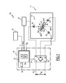
- a traction chain 10 for a railway vehicle illustrated on the figure 1 , comprises an electric motor 12 and a motor supply system 14 connected to an input supply DC voltage bus 16.
- the DC input voltage is of voltage U DC .
- the traction chain 10 also comprises means 18 for acquiring a signal representative of the engine torque, for example a target signal of the desired engine torque C and a sensor 20 for measuring the speed of rotation of the rotor Vrotor.
- the electric motor 12 comprises a drive shaft 22, a stator 24 and a rotor 26 integral with the shaft 22 and rotatable about the axis of the shaft 22.
- the motor 12 is, for example, a motor three-phase and synchronous. In a variant, the motor 12 is an asynchronous motor.
- the sensor 20 is either a sensor, in particular optical placed on the shaft 22 of the engine, or a sensor taking from the control electronics of the engine 12 a speed information of the engine, including a speed reference of the engine.
- the shaft 22 extends along an axis of symmetry of the motor 12.
- the stator 24 comprises, for example, three electromagnetic coils 28. Each coil 28 is made by winding a coil around a magnetic core.
- the stator 24 is able to generate a rotating field Hs1, also called the main stator magnetic field, under the activity of a suitable supply current Ip, also called main three-phase current.
- the rotor 26 is, for example, a permanent magnet axis of symmetry coincident with the axis of the shaft 22, and the motor 12 is a synchronous motor permanent magnet.
- the rotor 26 comprises one or more electromagnetic coils fed by a direct current.
- the magnet of the rotor 26 is intended to generate a magnetic field own rotor Hpr oriented in a first magnetic direction DM1 fixed relative to the rotor 26.
- the electromagnetic coil or coils of the rotor 26, supplied with direct current, are clean. generating the own rotor magnetic field Hpr according to the first magnetic direction DM1.
- the own rotor magnetic field Hpr creates an own flow of rotor ⁇ pr through the rotor 26, equal to the amount of a magnetic field own rotor Hpr which crosses for one second a cross section of the rotor 26.
- the power supply system 14 comprises a voltage inverter 30 for supplying the motor 12, and a device 32 for controlling the inverter.
- the voltage inverter 30 is able to convert the input DC voltage flowing on the input bus 16 into a three-phase output voltage delivered to the motor 12.
- the inverter 30 comprises, for each output phase, at least two controllable switches for converting DC voltage to AC voltage.
- Each switch of the inverter 30 is, for example, a bipolar transistor insulated gate, also called transistor IGBT (English Insulated Gate Bipolar Transistor).
- the control device 32 is connected to the acquisition means 18 to receive the target signal of the desired motor torque C, and to the measurement sensor 20 to receive the signal for measuring the rotational speed of the rotor Vrotor.
- the control device 32 is connected to the inverter 30 to deliver a signal 33 for controlling at least two switches of the inverter 30.
- the controller 32 includes an information processing unit formed, for example, of a data processor 34, associated with a memory 36.
- memory 36 comprises a first software 38 for generating the main three-phase current Ip and a second software 40 for generating an additional phase-shifted current Id.
- the first generation means 38 and the second generation means 40 are designed as programmable logic components or as dedicated integrated circuits.
- Each of the phases of the main three-phase current Ip generated by the first means 38 is intended to supply a respective electromagnetic coil 28 of the stator to create a coil magnetic field, the sum of the three coil fields forming the main stator magnetic field Hs1.
- the main stator magnetic field Hs1 is a field rotating around the motor shaft 22 and oriented in a second magnetic direction DM2 distinct from the first magnetic direction DM1.
- the orientation of the main stator magnetic field Hs1 is a function of the supply voltage of the respective electromagnetic coils 28.
- the first magnetic direction DM1 forms with the second magnetic direction DM2 an angle ⁇ on which the motor torque depends.
- the additional current Id generated by the second means 40 and out of phase with the main current Ip is intended to supply the stator 24 to create a secondary magnetic stator field Hs2 substantially oriented in the first magnetic direction DM1.
- the secondary magnetic field of stator Hs2 is of lower intensity than that of the own magnetic field of rotor Hpr.
- the intensity of the rotor magnetic field Hr is the difference between the intensity of the clean field of rotor Hpr and that of the field secondary magnetic stator Hs2.
- the intensity of the rotor magnetic field Hr is the sum of the intensities of the rotor clean field Hpr and the stator secondary magnetic field Hs2.
- the rotor magnetic field Hr creates a rotor magnetic field flux ⁇ r, also called rotor flux, equal to the amount of the rotor magnetic field Hr which passes through a cross section of the rotor 26 for one second.
- ⁇ r rotor magnetic field flux
- a modulation rate Tmod is equal to the voltage amplitude of each phase of the three-phase current divided by the voltage U DC of the input DC voltage.
- the modulation rate Tmod depends on the supply voltage of the motor 12, which itself depends on the rotor flow ⁇ r according to Park's equations.
- the figure 2 illustrates a method of controlling the traction chain 10.
- step 200 the measurement sensor 20 of the traction chain receives the signal for measuring the speed of the rotor Vrotor.
- step 210 the controller 32 determines whether the measured value of the rotor speed Vrotor belongs to a first interval of values INT1 of values less than a predetermined value of transition Vt. If necessary in step 220, means for varying the modulation rate Tmod reduce the modulation rate Tmod with respect to the modulation rate in the absence of modulation rate variation means.
- the relative decrease of the modulation rate Tmod is obtained, for example, by means of variation of the flow ⁇ r of the rotor magnetic field.
- the flux variation means reduces the flow ⁇ r of the rotor magnetic field with respect to the own rotor flow ⁇ pr. The flow ⁇ r is then smaller than the flux of the own rotor flow ⁇ pr.
- the variation of the modulation rate Tmod as a function of the speed of the rotor Vrotor is represented on the figure 3 .
- the rotor speed Vrotor is also called the rotor speed, or the motor rotation speed, the rotor 26 being the moving element of the motor 12.
- the rotor speed Vrotor is expressed in revolutions per minute.
- the dotted line curve comprises a first portion 50 for which the modulation rate Tmod is an affine function of the rotor speed Vrotor, the modulation ratio varying from 0% to 100%, and a second portion 52 for which the modulation ratio Tmod is substantially constant and equal to 100% for a rotor speed Vrotor greater than a full wave value Vpo.
- the second portion 52 is also called the full wave portion and corresponds to an operation of the motor 12 in the full wave regime.
- the curve in solid lines is substantially coincident with the curve in dashed lines for the values of the rotor speed Vrotor not belonging to the first interval INT1 and the second interval INT2.
- the modulation rate Tmod comprises a defluxing portion 54 for which the modulation rate Tmod is substantially constant and less than the corresponding values of the first portion 50 of the curve. dashed.
- step 220 corresponds to the defluxing portion 54.
- the control device 32 proceeds to step 230, where it determines whether the value of the rotor speed Vrotor belongs to the second interval INT2 of values greater than the predetermined value of transition Vt. If necessary at step 240, the modulation degree variation means Tmod increase the modulation rate Tmod with respect to the modulation rate in the absence of modulation rate variation means.
- the relative increase of the modulation rate Tmod is obtained, for example, by means of variation of the flow ⁇ r of the rotor magnetic field.
- the means of variation of the flux increase the flow ⁇ r of the rotor magnetic field with respect to the own rotor flow ⁇ pr.
- the flow ⁇ r is then greater than the own rotor flow ⁇ pr.
- Step 240 corresponds to an overflow portion 56 of the curve in solid lines, for which the modulation rate Tmod is substantially constant and greater than the corresponding values of the first portion 50 of the dashed curve.
- the controller 32 does not modify the modulation rate Tmod and returns to step 200.
- the defluxing portion 54 and the overflow portion 56 of the curve in solid lines of the figure 3 are interconnected by a connecting portion 58 substantially linear and vertical.
- the connecting portion 58 corresponds to the predetermined transition value Vt of the rotor speed.
- the predetermined value of transition Vt is greater than the value of the rotational speed of the rotor V 50% _sans corresponding to the modulation rate equal to 50% in the absence of modulation rate variation means.
- the second means 40 are able to generate an additional current Id of a first sign, so that the secondary magnetic field of the stator Hs2 generated is in the opposite direction to the Hpr rotor clean field.
- the intensity of the rotor magnetic field Hr is the difference between the intensity of the rotor clean field Hpr and that of the secondary stator magnetic field Hs2, so that the rotor flux ⁇ r is smaller than the own rotor flow ⁇ pr.
- the second means 40 are able to generate an additional current Id of sign opposite to the first sign, so that the secondary magnetic field of the stator Hs2 generated and the proper field Hpr rotor are of the same meaning.
- the intensity of the rotor magnetic field Hr is then the sum of the intensity of the rotor own field Hpr and that of the secondary magnetic stator field Hs2, so that the rotor flow ⁇ r is greater than the own rotor flow ⁇ pr .
- the additional current Id is of the first sign for the values of the rotor speed Vrotor belonging to the first interval INT1
- the additional current Id is of sign opposite to the first sign for the values of the rotation speed of the rotor Vrotor belonging to the second interval INT2.
- the first sign is the negative sign.
- the union of the first interval INT1 and the second interval INT2 is, for example, connected.
- the first interval INT1 is disjoined from the second interval INT2.
- the variation of harmonic losses Pertes_harm in the rotor 26 as a function of the rotor speed Vrotor is represented on the figure 3 , the curve in dotted lines corresponding to the variations of harmonic losses without implementation of the means of variation of the modulation rate, and the curve in solid lines corresponding to the variation of harmonic losses with implementation of the means of variation of the modulation rate .
- the dotted line curve of harmonic losses Pertes_harm has a first portion 60 substantially in the form of a parabola for values of the rotor speed Vrotor less than the full wave value Vpo and a second portion 62 substantially linear and decreasing for values of the rotor speed Vrotor greater than the full wave value Vpo.
- the first portion 60 has a maximum value Loss_max_sans for a modulation rate Tmod corresponding substantially equal to 50%.
- the solid line curve of the harmonic losses Pertes_harm is substantially merged with the dashed curve for the values of the rotor speed Vrotor that do not belong to the intervals INT1 and INT2.
- the curve in solid lines comprises a portion of variation of the flow 64 corresponding to the values of the rotor speed Vrotor belonging to the intervals INT1 and INT2.
- the portion of variation of the stream 64 is substantially linear and decreasing, and has values lower than the corresponding portion 60 of the dashed curve.
- the curve in solid lines has a maximum value Loss_max_with a value of the rotor speed Vrotor corresponding to the lower bound of the interval INT1.
- the maximum value Loss_max_with the curve in solid lines is lower than the maximum value Loss_max_without the curve in dashed lines.
- the curves 70 to 80 represent the evolution of the phase-shifted current Id as a function of the rotor speed Vrotor, for values of the setpoint of the desired motor torque C varying from 0.5% to 100%, in steps of 10%.
- the curves 70, 71, 72, 73, 74, 75, 76, 77, 78, 79 and 80 thus correspond to a value of the setpoint of the desired motor torque C equal to 0.5%, 10%, 20%, 30%, 40%, 50%, 60%, 70%, 80%, 90% and 100%.
- the intensity of the additional current Id depends on the value of the setpoint of the desired engine torque C.
- the absolute value of the intensity of the additional current Id is lower for the high values of the engine torque C than for the low values of the engine torque vs.
- the predetermined value of transition Vt depends on the value of the setpoint of the desired motor torque C.
- the predetermined value of transition Vt is lower for the high values of the engine torque C than for the low values of the engine torque C.
- the predetermined value of transition Vt varies between a minimum value Vt_min for the value of the desired motor torque C equal to 100%, and a maximum value Vt_max when the desired motor torque C is equal to 0.5%.
- the minimum value Vt_min is substantially equal to 1100 revolutions / minute
- the maximum value Vt_max is substantially equal to 1800 revolutions / minute.
- the predetermined value of transition Vt decreases from 1800 rpm to 1100 rpm when the value of the desired motor torque C increases from 0.5% to 100%.
- the predetermined value of transition Vt is not visible on the figure 4 for the values of the desired motor torque C equal to 90% and 100%, since the additional current Id is zero in this speed range.
- the full wave value Vpo is substantially independent of the value of the setpoint of the desired engine torque C, and is substantially equal to 2800 revolutions / minute.
- the first interval INT1 substantially corresponds to the values between 0 rpm and 1500 rpm
- the second interval INT2 substantially corresponds to values in the range of 1500 rpm to 3300 rpm.
- the curves 90 to 100 represent the evolution of the modulation rate Tmod expressed as a percentage, as a function of the rotor speed Vrotor, for values of the setpoint of the desired engine torque C ranging from 0.5% to 100%, in steps of of 10%.
- the curves 90, 91, 92, 93, 94, 95, 96, 97, 98, 99 and 100 thus correspond to values of the desired motor torque setpoint respectively equal to 0.5%, 10%, 20%, %, 40%, 50%, 60%, 70%, 80%, 90% and 100%.
- the modulation rate Tmod depends on the value of the setpoint of the desired motor torque C.
- the slope of the defluxing portion is lower for the low values of the setpoint of the desired motor torque C than for the high values of the torque setpoint.
- the deflowering portions of the curves 90 to 98 are substantially parallel to each other and of low slope, so that the variation of the modulation rate Tmod is low for the range of values of the rotor speed Vrotor included between 500 rpm and 1500 rpm.
- the defluxing portion of the modulation rate curve Tmod is substantially an affine function of the rotor speed Vrotor, and the modulation rate Tmod varies more significantly in the range of values of the speed.
- Vrotor rotor between 500 rpm and 1500 rpm, only for curves 90 to 98. This is related to the additional current Id which is zero for curves 99 and 100, in the speed range less than 1500 rpm .
- the predetermined value of transition Vt varies between the minimum value Vt_min substantially equal to 1100 revolutions / minute for the value of the desired motor torque C equal to 100%, and the maximum value Vt_max substantially equal to 1800 revolutions / minute for the value of the torque desired motor C equal to 0.5%.
- Each of the curves 90 to 100 has a horizontal portion 102, distinct from the defluxing portion 56 of the figure 3 , for which the value of the modulation rate Tmod is substantially constant and equal to 95%.
- This horizontal portion 102 makes it possible to comply with temperature constraints that are a function of the switching losses of the inverter 30.
- the horizontal portion 102 corresponds to values of the rotor speed Vrotor of between about 1900 rpm. minute and 2700 rpm.
- the horizontal portion 102 corresponds to values of the rotor speed Vrotor of between about 2000 revolutions / minute and 2700 revolutions / minute.
- the horizontal portion 102 corresponds to values of the rotor speed Vrotor of between about 2300 revolutions / minute and 2700 revolutions / minute.
- Each of the curves 90 to 100 comprises the full wave portion 52 for which the value of the modulation rate Tmod is substantially constant and equal to 100%.
- the full wave value Vpo is substantially identical for all the values of the setpoint of the desired engine torque C, and is substantially equal to 2800 revolutions / minute.
- the curves 110 to 120 represent the evolution of harmonic losses Pertes_harm in the rotor of a motor of the state of the art, expressed in kW, as a function of the rotor speed Vrotor, for values of the setpoint of the engine torque desired C ranging from 0.5% to 100%, in steps of 10%.
- the curves 110, 111, 112, 113, 114, 115, 116, 117, 118, 119 and 120 thus correspond to a value of the setpoint of the desired motor torque C respectively equal to 0.5%, 10%, 20%, 30%, 40%, 50%, 60%, 70%, 80%, 90% and 100%.
- Each of the harmonic loss curves 110 to 120 Pertes_harm comprises substantially vertical portions for five distinct values Vs1, Vs2, Vs3, Vs4 and Vs5 of the rotor speed. These vertical portions correspond to significant variations in harmonic losses Pertes_harm, especially for the values Vs3, Vs4 and Vs5 of the rotor speed.
- the three-phase voltage delivered to the motor is, for example, modulated in pulse width.
- the five separate values Vs1, Vs2, Vs3, Vs4 and Vs5 of the rotor speed each correspond to a change from one pulse width modulation to another pulse width modulation.
- the curves 110 to 120 are substantially close to each other, and the maximum harmonic loss difference between the end curves 110 and 120 is substantially less than 2 kW for any value of the rotor speed less than 2000 revolutions / minute. Between 2000 rpm and 2500 rpm, the maximum harmonic loss difference between the end curves 110 and 120 is substantially between 2kW and 3kW. Beyond 2500 rpm, the maximum difference in harmonic losses between the extremal curves 110 and 120 decreases progressively from 2kW to a substantially zero difference beyond 3350 revolutions / minute.
- the harmonic losses are substantially between 2.5 kW and 3.5 kW for the curve 110 and between 4.5 kW and 5.75 kW for the curve 120.
- the harmonic losses are substantially between 5 kW for the curve 110 and 7 kW for the curve 120.
- the harmonic losses go through a maximum of between 8.25 kW for the curve 110 and 10 kW for the curve 120, for the value of the rotor speed equal to Vs5.
- the full wave value Vpo depends on the value of the setpoint of the desired motor torque C, when the modulation rate variation means are not implemented.
- the full wave value Vpo is between approximately 2600 revolutions / minute for the value of the setpoint of the desired motor torque C equal to 100%, and approximately 3350 revolutions / minute for the value of the setpoint of the desired motor torque C equal to 0.5%.
- the curves 110 to 120 are substantially merged, and have harmonic loss values Pertes_harm less than 2 kW.
- the curves 130 to 140 represent the evolution of harmonic losses Pertes_harm in the rotor 26 of the motor, expressed in kW, as a function of the rotor speed Vrotor, for values of the setpoint of the desired engine torque C varying by 0.5% 100%, in steps of 10%.
- the curves 130, 131, 132, 133, 134, 135, 136, 137, 138, 139 and 140 thus correspond to a value of the setpoint of the desired motor torque C respectively equal to 0.5%, 10%, 20%, 30%, 40%, 50%, 60%, 70%, 80%, 90% and 100%.
- the predetermined value of transition Vt varies between the minimum value Vt_min substantially equal to 1100 revolutions / minute for the value of the desired motor torque C equal to 100%, and the maximum value Vt_max substantially equal to 1800 revolutions / minute for the value of the torque desired motor C equal to 0.5%.
- the full wave value Vpo is substantially equal to 2800 revolutions / minute for all the curves 130 to 140.
- the transition value Vt corresponds to an inflection point of the corresponding harmonic loss curve.
- the harmonic loss values Pertes_harm decrease significantly for each of the curves 130 to 140, when the rotor speed Vrotor is greater than the transition value Vt.
- each of the Harmes loss curves Harmes loss curves 150 to 140 comprises substantially vertical portions for five distinct values Vs1, Vs2, Vs3, Vs4 and Vs5 of the rotor speed, each corresponding to a change from a one-to-one pulse width modulation. other pulse width modulation. These vertical portions correspond to significant variations in harmonic losses Pertes_harm, especially for the values Vs4 and Vs5 of the rotor speed.
- the maximum difference in harmonic losses between the extremal curves 130 and 140 is substantially greater than 3 kW for any value of the rotor speed between Vs3 and Vt_max.
- the curves 130 to 140 are substantially merged, and have harmonic loss values Pertes_harm less than 2 kW.
- the harmonic losses are substantially between 2 kW for the curve 130 and between 4.5 kW and 5.75 kW for the curve 140.
- the harmonic losses are substantially between 2.25 kW and 3 kW for the curve 130 and 7 kW for the curve 140.
- the harmonic losses go through a maximum of between 4 kW for the curve 130 for the value of the rotor speed equal to Vt_max, and 10 kW for the curve 140 for the value of the rotor speed equal to Vs5.
- the harmonic losses corresponding to the curves 120 and 140 are substantially identical for all the values of the rotor speed.
- the harmonic losses with implementation of the modulation rate variation means are even lower than the value of the motor torque setpoint is low.
- the harmonic losses with implementation of the modulation rate variation means are comparatively much lower than those without implementation of the modulation rate variation means for the low values of the motor torque setpoint, than for the high values. values of the motor torque setpoint.
- the traction chain 10 makes it possible to reduce the flux ⁇ r of the rotor magnetic field with respect to the own flow of the rotor ⁇ pr, when the rotational speed of the rotor Vrotor belongs to the first interval INT1.
- This decrease in the rotor flow ⁇ r causes a decrease in the motor supply voltage.
- This reduction in the supply voltage of the motor 12 causes a slower evolution of the modulation rate Tmod in the defluxing portion 54.
- the value of the modulation rate Tmod is less than 50%, which reduces harmonic losses. Indeed, the value of the modulation rate Tmod equal to 50% is substantially the value that generates the greatest harmonic losses.
- the traction chain 10 also makes it possible to increase the flow of the rotor field ⁇ r with respect to the own flow of the rotor ⁇ pr, when the rotational speed of the rotor Vrotor belongs to a second interval INT2 of values greater than the value predetermined transition Vt.
- This increase of the rotor flow ⁇ r causes an increase in the supply voltage, and consequently a faster evolution of the modulation rate Tmod in the overflow portion 56.
- This greater evolution of the modulation rate Tmod does not result in a change in the modulation rate Tmod.
- increased harmonic losses Pertes_harm since the overflow portion 56 succeeds the defluxing portion 54 for which the value of the modulation rate equal to 50% and its corresponding maximum of harmonic losses have been avoided.
- the traction chain according to the invention makes it possible to reduce the losses generated by the Joule and Foucault effect in the rotor.
Landscapes
- Engineering & Computer Science (AREA)
- Power Engineering (AREA)
- Transportation (AREA)
- Mechanical Engineering (AREA)
- Control Of Ac Motors In General (AREA)
- Electric Propulsion And Braking For Vehicles (AREA)
- Control Of Motors That Do Not Use Commutators (AREA)
Applications Claiming Priority (1)
| Application Number | Priority Date | Filing Date | Title |
|---|---|---|---|
| FR1056370A FR2963510B1 (fr) | 2010-08-02 | 2010-08-02 | Chaine de traction pour un vehicule de transport, notamment ferroviaire, et procede de commande d'une telle chaine |
Publications (3)
| Publication Number | Publication Date |
|---|---|
| EP2416490A2 true EP2416490A2 (de) | 2012-02-08 |
| EP2416490A3 EP2416490A3 (de) | 2015-10-28 |
| EP2416490B1 EP2416490B1 (de) | 2019-05-01 |
Family
ID=43971305
Family Applications (1)
| Application Number | Title | Priority Date | Filing Date |
|---|---|---|---|
| EP11306003.2A Active EP2416490B1 (de) | 2010-08-02 | 2011-08-01 | Zugkette für ein transportfahrzeug, insbesondere ein schienenfahrzeug, und steuerverfahren für eine solche kette |
Country Status (6)
| Country | Link |
|---|---|
| US (1) | US8519661B2 (de) |
| EP (1) | EP2416490B1 (de) |
| JP (2) | JP2012034571A (de) |
| CN (1) | CN102381323B (de) |
| FR (1) | FR2963510B1 (de) |
| RU (1) | RU2561200C2 (de) |
Family Cites Families (44)
| Publication number | Priority date | Publication date | Assignee | Title |
|---|---|---|---|---|
| DE975999C (de) * | 1944-09-16 | 1963-01-10 | Siemens Ag | Verfahren und Einrichtung zum Betrieb von Einphasenbahnfahrleitungen, die von mindestens zwei Speisepunkten aus gespeist werden |
| DE1263065B (de) * | 1961-02-16 | 1968-03-14 | Licentia Gmbh | Antrieb fuer aus einem Einphasen-wechselstromnetz gespeiste Lokomotiven oder Triebwagen mit Drehstromkurzschluss-laeufermotoren als Fahrmotoren |
| JPH0797915B2 (ja) * | 1987-05-28 | 1995-10-18 | 三菱電機株式会社 | 同期電動機の制御装置 |
| DE3912837A1 (de) * | 1989-04-19 | 1990-10-25 | Thomson Brandt Gmbh | Regelschaltung |
| US5030871A (en) * | 1990-05-11 | 1991-07-09 | General Electric Company | Reducing harmonic losses in dynamoelectric machine rotors |
| JP2814837B2 (ja) * | 1992-06-04 | 1998-10-27 | 株式会社日立製作所 | 電力変換装置 |
| US6465977B1 (en) * | 2001-11-29 | 2002-10-15 | Ecostar Electric Drive Systems L.L.C. | System and method for controlling torque in an electrical machine |
| JP4082127B2 (ja) * | 2002-08-08 | 2008-04-30 | 日産自動車株式会社 | モーター制御装置および方法 |
| RU39763U1 (ru) * | 2004-04-06 | 2004-08-10 | Открытое акционерное общество "Всероссийский научно-исследовательский и проектно-конструкторский институт электровозостроения" | Схема питания трехфазного асинхронного двигателя |
| JP2006050764A (ja) * | 2004-08-04 | 2006-02-16 | Toyota Motor Corp | モータ制御装置 |
| EP1653602B1 (de) * | 2004-10-29 | 2019-07-03 | Nissan Motor Co., Ltd. | Antriebssystem und Verfahren für einen Motor |
| JP4641179B2 (ja) * | 2004-11-25 | 2011-03-02 | 川崎重工業株式会社 | 同期モータの制御方法および制御装置 |
| JP4561616B2 (ja) * | 2005-10-27 | 2010-10-13 | トヨタ自動車株式会社 | モータ駆動システム |
| CN100574090C (zh) * | 2005-12-26 | 2009-12-23 | 日产自动车株式会社 | 电功率转换设备 |
| EP1833151B1 (de) * | 2006-03-07 | 2017-06-14 | Nissan Motor Co., Ltd. | Leistungsumwandlungseinrichtung |
| JP4466599B2 (ja) * | 2006-03-31 | 2010-05-26 | アイシン・エィ・ダブリュ株式会社 | 電動駆動制御装置及び電動駆動制御方法 |
| JP2008035688A (ja) * | 2006-06-26 | 2008-02-14 | Sanyo Electric Co Ltd | 電動機の駆動装置 |
| JP4720653B2 (ja) * | 2006-07-07 | 2011-07-13 | トヨタ自動車株式会社 | 電動機制御装置およびそれを備えた車両 |
| JP5121200B2 (ja) * | 2006-09-26 | 2013-01-16 | 株式会社東芝 | 永久磁石電動機の制御装置 |
| US7449859B2 (en) * | 2007-02-20 | 2008-11-11 | Gm Global Technology Operations, Inc. | Reduction of subharmonic oscillation at high frequency operation of a power inverter |
| JP4729526B2 (ja) * | 2007-03-29 | 2011-07-20 | トヨタ自動車株式会社 | 電動機の駆動制御装置 |
| JP4985956B2 (ja) * | 2007-04-13 | 2012-07-25 | 本田技研工業株式会社 | 電動機の制御装置 |
| WO2009038047A1 (ja) * | 2007-09-18 | 2009-03-26 | Kabushiki Kaisha Toshiba | 可変磁束ドライブシステム |
| JP4329855B2 (ja) * | 2007-10-09 | 2009-09-09 | トヨタ自動車株式会社 | 交流モータの制御装置および交流モータの制御方法 |
| CN101796717B (zh) * | 2007-10-29 | 2013-06-19 | 三菱电机株式会社 | 电动机的控制装置 |
| US8344680B2 (en) * | 2007-12-04 | 2013-01-01 | Mitsubishi Electric Corporation | Control apparatus of alternating-current motor |
| DE102008062515A1 (de) * | 2007-12-21 | 2009-06-25 | Denso Corporation, Kariya | Vorrichtung zum Steuern eines Drehmoments einer elektrischen Drehmaschine |
| JP4424427B2 (ja) * | 2008-03-18 | 2010-03-03 | トヨタ自動車株式会社 | 車両の制御装置および制御方法 |
| JP4458174B2 (ja) * | 2008-03-21 | 2010-04-28 | 株式会社デンソー | 回転機の制御装置、及び回転機の制御システム |
| JP4582168B2 (ja) * | 2008-03-21 | 2010-11-17 | 株式会社デンソー | 回転機の制御装置、及び回転機の制御システム |
| JP4770883B2 (ja) * | 2008-06-25 | 2011-09-14 | 株式会社デンソー | 回転機の制御装置、及び回転機の制御システム |
| JP4497235B2 (ja) * | 2008-08-08 | 2010-07-07 | トヨタ自動車株式会社 | 交流電動機の制御装置および制御方法 |
| JP5281339B2 (ja) * | 2008-09-01 | 2013-09-04 | 株式会社日立製作所 | 同期電動機の駆動システム、及びこれに用いる制御装置 |
| JP4506889B2 (ja) * | 2008-10-23 | 2010-07-21 | トヨタ自動車株式会社 | 交流電動機の制御装置および制御方法 |
| JP5191351B2 (ja) * | 2008-11-05 | 2013-05-08 | 三菱電機株式会社 | 電力変換装置 |
| JP5368777B2 (ja) * | 2008-11-17 | 2013-12-18 | トヨタ自動車株式会社 | 交流電動機の制御装置 |
| JP5281370B2 (ja) * | 2008-11-25 | 2013-09-04 | トヨタ自動車株式会社 | 交流電動機の制御装置 |
| JP2010130752A (ja) * | 2008-11-26 | 2010-06-10 | Honda Motor Co Ltd | 電動機の相電流推定装置 |
| JP4858597B2 (ja) * | 2008-11-28 | 2012-01-18 | 株式会社デンソー | 回転機の制御装置及びその製造方法 |
| JP4329880B1 (ja) * | 2009-01-14 | 2009-09-09 | トヨタ自動車株式会社 | 交流電動機の制御装置および電動車両 |
| JP5056817B2 (ja) * | 2009-08-25 | 2012-10-24 | 株式会社デンソー | 回転機の制御装置 |
| JP5471259B2 (ja) * | 2009-10-02 | 2014-04-16 | アイシン・エィ・ダブリュ株式会社 | 制御装置 |
| JP5252229B2 (ja) * | 2009-10-02 | 2013-07-31 | アイシン・エィ・ダブリュ株式会社 | 電動機駆動装置の制御装置 |
| RU2414792C1 (ru) * | 2009-12-28 | 2011-03-20 | Владимир Михайлович Чернухин | Бесконтактная магнитоэлектрическая машина с модулированной мдс якоря |
-
2010
- 2010-08-02 FR FR1056370A patent/FR2963510B1/fr not_active Expired - Fee Related
-
2011
- 2011-08-01 EP EP11306003.2A patent/EP2416490B1/de active Active
- 2011-08-01 RU RU2011132456/11A patent/RU2561200C2/ru active
- 2011-08-01 JP JP2011168243A patent/JP2012034571A/ja active Pending
- 2011-08-02 US US13/196,377 patent/US8519661B2/en active Active
- 2011-08-02 CN CN201110274702.5A patent/CN102381323B/zh active Active
-
2016
- 2016-08-10 JP JP2016157408A patent/JP6228277B2/ja active Active
Non-Patent Citations (1)
| Title |
|---|
| None |
Also Published As
| Publication number | Publication date |
|---|---|
| JP2016192900A (ja) | 2016-11-10 |
| EP2416490A3 (de) | 2015-10-28 |
| JP6228277B2 (ja) | 2017-11-08 |
| FR2963510B1 (fr) | 2012-10-05 |
| US20120056576A1 (en) | 2012-03-08 |
| CN102381323A (zh) | 2012-03-21 |
| EP2416490B1 (de) | 2019-05-01 |
| RU2561200C2 (ru) | 2015-08-27 |
| JP2012034571A (ja) | 2012-02-16 |
| CN102381323B (zh) | 2015-11-25 |
| US8519661B2 (en) | 2013-08-27 |
| FR2963510A1 (fr) | 2012-02-03 |
| RU2011132456A (ru) | 2013-02-10 |
Similar Documents
| Publication | Publication Date | Title |
|---|---|---|
| EP1881594B1 (de) | Verfahren zur Justierung der Parameter eines Synchronmotors und Verwendung eines solchen Verfahrens in einer Drehzahlregelung | |
| EP1020019B1 (de) | Gerät und verfahren zur steuerung eines synchronmotors mit permanentmagnet | |
| FR2753319A1 (fr) | Dispositif de detection de la position angulaire pour le pilotage d'un moteur synchrone a excitation par aimant permanent | |
| EP2400659B1 (de) | Elektrische Vorrichtung, die einen Wechselstrommotor und einen Steuerumrichter umfasst, sowie ein Verfahren zur Messung der elektromotorischen Kraft dieser Vorrichtung | |
| WO2012107665A2 (fr) | Procede et dispositif de pilotage d'une machine electrique a reluctance | |
| FR2486328A1 (fr) | Dispositif perfectionne d'economie d'energie pour moteurs a induction | |
| FR3056360A1 (fr) | Moto-reducteur, systeme d'essuyage et procede de commande associes | |
| FR2917917A1 (fr) | Detection de position d'un rotor a l'arret et a vitesse reduite | |
| EP2416490B1 (de) | Zugkette für ein transportfahrzeug, insbesondere ein schienenfahrzeug, und steuerverfahren für eine solche kette | |
| EP1233506B1 (de) | Regelverfahren und Vorrichtung für eine rotierende elektrische Wechselstrommaschine, insbesondere Synchronmaschine | |
| WO2017089697A1 (fr) | Procédé de commande d'une machine synchrone à aimants permanents, et dispositif correspondant | |
| EP1484835B1 (de) | Verfahren und System zum Steuern des augenblickligen elektromagnetischen Drehmoments, und Datenträger zum Durchführen des Verfahrens | |
| FR3035283A1 (fr) | Procede de controle du couple d'une machine electrique synchrone | |
| EP0388845B1 (de) | Vektorregelungssystem für elektrischen Induktionsmotor mit Kurzschlussläufer | |
| CA2840184A1 (fr) | Methode de regulation de la puissance d'une installation de conversion d'energie et installation de conversion d'energie pilotee par une telle methode | |
| EP3888240A1 (de) | Steuerungsverfahren und zugehöriges steuerungssystem | |
| WO2016038296A1 (fr) | Système et procédé de commande d'une machine électrique asynchrone | |
| EP0702451A1 (de) | Steuervorrichtung eines Synchronmotors | |
| FR2714773A1 (fr) | Moteur synchrone à aimants permanents et à commutation électronique. | |
| EP2787632B1 (de) | Verfahren und Vorrichtung zum Steuern einer doppelten elektrisch umlaufenden Maschine mit Drehstromantrieb, und entsprechende elektrisch umlaufende Maschine | |
| EP4042562A1 (de) | Antriebssystem zum antrieb einer fluidverdichtungsvorrichtung und zugehöriges stromversorgungsverfahren | |
| FR2806853A1 (fr) | Machine a reluctance commutee a capteurs de position magnetiques | |
| WO2015040305A2 (fr) | Machine electrique comprenant au moins un capteur integre pour la detection de la position des poles magnetiques de son rotor | |
| WO2021069229A1 (fr) | Systeme d'entrainement d'un dispositif de compression de fluide et procede d'alimentation electrique associe | |
| EP2870684A1 (de) | Elektrische drehmaschine mit kompensation von magnetischer ankerrückkopplung |
Legal Events
| Date | Code | Title | Description |
|---|---|---|---|
| AK | Designated contracting states |
Kind code of ref document: A2 Designated state(s): AL AT BE BG CH CY CZ DE DK EE ES FI FR GB GR HR HU IE IS IT LI LT LU LV MC MK MT NL NO PL PT RO RS SE SI SK SM TR |
|
| AX | Request for extension of the european patent |
Extension state: BA ME |
|
| PUAI | Public reference made under article 153(3) epc to a published international application that has entered the european phase |
Free format text: ORIGINAL CODE: 0009012 |
|
| RAP1 | Party data changed (applicant data changed or rights of an application transferred) |
Owner name: ALSTOM TRANSPORT TECHNOLOGIES |
|
| PUAL | Search report despatched |
Free format text: ORIGINAL CODE: 0009013 |
|
| AK | Designated contracting states |
Kind code of ref document: A3 Designated state(s): AL AT BE BG CH CY CZ DE DK EE ES FI FR GB GR HR HU IE IS IT LI LT LU LV MC MK MT NL NO PL PT RO RS SE SI SK SM TR |
|
| AX | Request for extension of the european patent |
Extension state: BA ME |
|
| RIC1 | Information provided on ipc code assigned before grant |
Ipc: B60L 15/20 20060101ALI20150923BHEP Ipc: H02P 21/00 20060101ALI20150923BHEP Ipc: H02P 29/00 20060101ALI20150923BHEP Ipc: H02P 27/08 20060101ALI20150923BHEP Ipc: B60L 15/02 20060101ALI20150923BHEP Ipc: H02P 6/08 20060101AFI20150923BHEP |
|
| 17P | Request for examination filed |
Effective date: 20160428 |
|
| RBV | Designated contracting states (corrected) |
Designated state(s): AL AT BE BG CH CY CZ DE DK EE ES FI FR GB GR HR HU IE IS IT LI LT LU LV MC MK MT NL NO PL PT RO RS SE SI SK SM TR |
|
| RAP1 | Party data changed (applicant data changed or rights of an application transferred) |
Owner name: ALSTOM TRANSPORT TECHNOLOGIES |
|
| STAA | Information on the status of an ep patent application or granted ep patent |
Free format text: STATUS: EXAMINATION IS IN PROGRESS |
|
| 17Q | First examination report despatched |
Effective date: 20180223 |
|
| REG | Reference to a national code |
Ref country code: DE Ref legal event code: R079 Ref document number: 602011058469 Country of ref document: DE Free format text: PREVIOUS MAIN CLASS: H02P0006080000 Ipc: H02P0029500000 |
|
| RIN1 | Information on inventor provided before grant (corrected) |
Inventor name: GIACOMONI, OLIVIER Inventor name: DESPORTES, GUILLAUME Inventor name: BELIN, SEBASTIEN Inventor name: CYPERS, DAVID |
|
| GRAP | Despatch of communication of intention to grant a patent |
Free format text: ORIGINAL CODE: EPIDOSNIGR1 |
|
| STAA | Information on the status of an ep patent application or granted ep patent |
Free format text: STATUS: GRANT OF PATENT IS INTENDED |
|
| RIC1 | Information provided on ipc code assigned before grant |
Ipc: H02P 21/00 20060101ALI20181025BHEP Ipc: B60L 15/02 20060101ALI20181025BHEP Ipc: H02P 29/50 20120208AFI20181025BHEP Ipc: H02P 15/02 20060101ALI20181025BHEP |
|
| INTG | Intention to grant announced |
Effective date: 20181121 |
|
| RIN1 | Information on inventor provided before grant (corrected) |
Inventor name: GIACOMONI, OLIVIER Inventor name: CYPERS, DAVID Inventor name: BELIN, SEBASTIEN Inventor name: DESPORTES, GUILLAUME |
|
| RIC1 | Information provided on ipc code assigned before grant |
Ipc: H02P 21/00 20160101ALI20181025BHEP Ipc: B60L 15/02 20060101ALI20181025BHEP Ipc: H02P 15/02 20060101ALI20181025BHEP Ipc: H02P 29/50 20160101AFI20181025BHEP |
|
| RIC1 | Information provided on ipc code assigned before grant |
Ipc: H02P 15/02 20060101ALI20181025BHEP Ipc: B60L 15/02 20060101ALI20181025BHEP Ipc: H02P 21/00 20160101ALI20181025BHEP Ipc: H02P 29/50 20160101AFI20181025BHEP |
|
| GRAS | Grant fee paid |
Free format text: ORIGINAL CODE: EPIDOSNIGR3 |
|
| GRAA | (expected) grant |
Free format text: ORIGINAL CODE: 0009210 |
|
| STAA | Information on the status of an ep patent application or granted ep patent |
Free format text: STATUS: THE PATENT HAS BEEN GRANTED |
|
| AK | Designated contracting states |
Kind code of ref document: B1 Designated state(s): AL AT BE BG CH CY CZ DE DK EE ES FI FR GB GR HR HU IE IS IT LI LT LU LV MC MK MT NL NO PL PT RO RS SE SI SK SM TR |
|
| REG | Reference to a national code |
Ref country code: GB Ref legal event code: FG4D Free format text: NOT ENGLISH |
|
| REG | Reference to a national code |
Ref country code: CH Ref legal event code: EP Ref country code: AT Ref legal event code: REF Ref document number: 1128267 Country of ref document: AT Kind code of ref document: T Effective date: 20190515 |
|
| REG | Reference to a national code |
Ref country code: DE Ref legal event code: R096 Ref document number: 602011058469 Country of ref document: DE |
|
| REG | Reference to a national code |
Ref country code: IE Ref legal event code: FG4D Free format text: LANGUAGE OF EP DOCUMENT: FRENCH |
|
| REG | Reference to a national code |
Ref country code: CH Ref legal event code: NV Representative=s name: MICHELI AND CIE SA, CH |
|
| REG | Reference to a national code |
Ref country code: NL Ref legal event code: MP Effective date: 20190501 |
|
| REG | Reference to a national code |
Ref country code: LT Ref legal event code: MG4D |
|
| PG25 | Lapsed in a contracting state [announced via postgrant information from national office to epo] |
Ref country code: ES Free format text: LAPSE BECAUSE OF FAILURE TO SUBMIT A TRANSLATION OF THE DESCRIPTION OR TO PAY THE FEE WITHIN THE PRESCRIBED TIME-LIMIT Effective date: 20190501 Ref country code: NL Free format text: LAPSE BECAUSE OF FAILURE TO SUBMIT A TRANSLATION OF THE DESCRIPTION OR TO PAY THE FEE WITHIN THE PRESCRIBED TIME-LIMIT Effective date: 20190501 Ref country code: HR Free format text: LAPSE BECAUSE OF FAILURE TO SUBMIT A TRANSLATION OF THE DESCRIPTION OR TO PAY THE FEE WITHIN THE PRESCRIBED TIME-LIMIT Effective date: 20190501 Ref country code: LT Free format text: LAPSE BECAUSE OF FAILURE TO SUBMIT A TRANSLATION OF THE DESCRIPTION OR TO PAY THE FEE WITHIN THE PRESCRIBED TIME-LIMIT Effective date: 20190501 Ref country code: NO Free format text: LAPSE BECAUSE OF FAILURE TO SUBMIT A TRANSLATION OF THE DESCRIPTION OR TO PAY THE FEE WITHIN THE PRESCRIBED TIME-LIMIT Effective date: 20190801 Ref country code: PT Free format text: LAPSE BECAUSE OF FAILURE TO SUBMIT A TRANSLATION OF THE DESCRIPTION OR TO PAY THE FEE WITHIN THE PRESCRIBED TIME-LIMIT Effective date: 20190901 Ref country code: FI Free format text: LAPSE BECAUSE OF FAILURE TO SUBMIT A TRANSLATION OF THE DESCRIPTION OR TO PAY THE FEE WITHIN THE PRESCRIBED TIME-LIMIT Effective date: 20190501 Ref country code: SE Free format text: LAPSE BECAUSE OF FAILURE TO SUBMIT A TRANSLATION OF THE DESCRIPTION OR TO PAY THE FEE WITHIN THE PRESCRIBED TIME-LIMIT Effective date: 20190501 Ref country code: AL Free format text: LAPSE BECAUSE OF FAILURE TO SUBMIT A TRANSLATION OF THE DESCRIPTION OR TO PAY THE FEE WITHIN THE PRESCRIBED TIME-LIMIT Effective date: 20190501 |
|
| PG25 | Lapsed in a contracting state [announced via postgrant information from national office to epo] |
Ref country code: LV Free format text: LAPSE BECAUSE OF FAILURE TO SUBMIT A TRANSLATION OF THE DESCRIPTION OR TO PAY THE FEE WITHIN THE PRESCRIBED TIME-LIMIT Effective date: 20190501 Ref country code: GR Free format text: LAPSE BECAUSE OF FAILURE TO SUBMIT A TRANSLATION OF THE DESCRIPTION OR TO PAY THE FEE WITHIN THE PRESCRIBED TIME-LIMIT Effective date: 20190802 Ref country code: BG Free format text: LAPSE BECAUSE OF FAILURE TO SUBMIT A TRANSLATION OF THE DESCRIPTION OR TO PAY THE FEE WITHIN THE PRESCRIBED TIME-LIMIT Effective date: 20190801 Ref country code: RS Free format text: LAPSE BECAUSE OF FAILURE TO SUBMIT A TRANSLATION OF THE DESCRIPTION OR TO PAY THE FEE WITHIN THE PRESCRIBED TIME-LIMIT Effective date: 20190501 |
|
| PG25 | Lapsed in a contracting state [announced via postgrant information from national office to epo] |
Ref country code: IS Free format text: LAPSE BECAUSE OF FAILURE TO SUBMIT A TRANSLATION OF THE DESCRIPTION OR TO PAY THE FEE WITHIN THE PRESCRIBED TIME-LIMIT Effective date: 20190901 |
|
| PG25 | Lapsed in a contracting state [announced via postgrant information from national office to epo] |
Ref country code: CZ Free format text: LAPSE BECAUSE OF FAILURE TO SUBMIT A TRANSLATION OF THE DESCRIPTION OR TO PAY THE FEE WITHIN THE PRESCRIBED TIME-LIMIT Effective date: 20190501 Ref country code: RO Free format text: LAPSE BECAUSE OF FAILURE TO SUBMIT A TRANSLATION OF THE DESCRIPTION OR TO PAY THE FEE WITHIN THE PRESCRIBED TIME-LIMIT Effective date: 20190501 Ref country code: SK Free format text: LAPSE BECAUSE OF FAILURE TO SUBMIT A TRANSLATION OF THE DESCRIPTION OR TO PAY THE FEE WITHIN THE PRESCRIBED TIME-LIMIT Effective date: 20190501 Ref country code: EE Free format text: LAPSE BECAUSE OF FAILURE TO SUBMIT A TRANSLATION OF THE DESCRIPTION OR TO PAY THE FEE WITHIN THE PRESCRIBED TIME-LIMIT Effective date: 20190501 Ref country code: DK Free format text: LAPSE BECAUSE OF FAILURE TO SUBMIT A TRANSLATION OF THE DESCRIPTION OR TO PAY THE FEE WITHIN THE PRESCRIBED TIME-LIMIT Effective date: 20190501 |
|
| REG | Reference to a national code |
Ref country code: DE Ref legal event code: R097 Ref document number: 602011058469 Country of ref document: DE |
|
| PG25 | Lapsed in a contracting state [announced via postgrant information from national office to epo] |
Ref country code: IT Free format text: LAPSE BECAUSE OF FAILURE TO SUBMIT A TRANSLATION OF THE DESCRIPTION OR TO PAY THE FEE WITHIN THE PRESCRIBED TIME-LIMIT Effective date: 20190501 Ref country code: SM Free format text: LAPSE BECAUSE OF FAILURE TO SUBMIT A TRANSLATION OF THE DESCRIPTION OR TO PAY THE FEE WITHIN THE PRESCRIBED TIME-LIMIT Effective date: 20190501 |
|
| PLBE | No opposition filed within time limit |
Free format text: ORIGINAL CODE: 0009261 |
|
| STAA | Information on the status of an ep patent application or granted ep patent |
Free format text: STATUS: NO OPPOSITION FILED WITHIN TIME LIMIT |
|
| PG25 | Lapsed in a contracting state [announced via postgrant information from national office to epo] |
Ref country code: TR Free format text: LAPSE BECAUSE OF FAILURE TO SUBMIT A TRANSLATION OF THE DESCRIPTION OR TO PAY THE FEE WITHIN THE PRESCRIBED TIME-LIMIT Effective date: 20190501 |
|
| 26N | No opposition filed |
Effective date: 20200204 |
|
| GBPC | Gb: european patent ceased through non-payment of renewal fee |
Effective date: 20190801 |
|
| PG25 | Lapsed in a contracting state [announced via postgrant information from national office to epo] |
Ref country code: PL Free format text: LAPSE BECAUSE OF FAILURE TO SUBMIT A TRANSLATION OF THE DESCRIPTION OR TO PAY THE FEE WITHIN THE PRESCRIBED TIME-LIMIT Effective date: 20190501 |
|
| PG25 | Lapsed in a contracting state [announced via postgrant information from national office to epo] |
Ref country code: SI Free format text: LAPSE BECAUSE OF FAILURE TO SUBMIT A TRANSLATION OF THE DESCRIPTION OR TO PAY THE FEE WITHIN THE PRESCRIBED TIME-LIMIT Effective date: 20190501 Ref country code: MC Free format text: LAPSE BECAUSE OF FAILURE TO SUBMIT A TRANSLATION OF THE DESCRIPTION OR TO PAY THE FEE WITHIN THE PRESCRIBED TIME-LIMIT Effective date: 20190501 Ref country code: LU Free format text: LAPSE BECAUSE OF NON-PAYMENT OF DUE FEES Effective date: 20190801 |
|
| REG | Reference to a national code |
Ref country code: BE Ref legal event code: MM Effective date: 20190831 |
|
| PG25 | Lapsed in a contracting state [announced via postgrant information from national office to epo] |
Ref country code: IE Free format text: LAPSE BECAUSE OF NON-PAYMENT OF DUE FEES Effective date: 20190801 |
|
| PG25 | Lapsed in a contracting state [announced via postgrant information from national office to epo] |
Ref country code: GB Free format text: LAPSE BECAUSE OF NON-PAYMENT OF DUE FEES Effective date: 20190801 Ref country code: BE Free format text: LAPSE BECAUSE OF NON-PAYMENT OF DUE FEES Effective date: 20190831 |
|
| REG | Reference to a national code |
Ref country code: AT Ref legal event code: UEP Ref document number: 1128267 Country of ref document: AT Kind code of ref document: T Effective date: 20190501 |
|
| PG25 | Lapsed in a contracting state [announced via postgrant information from national office to epo] |
Ref country code: CY Free format text: LAPSE BECAUSE OF FAILURE TO SUBMIT A TRANSLATION OF THE DESCRIPTION OR TO PAY THE FEE WITHIN THE PRESCRIBED TIME-LIMIT Effective date: 20190501 |
|
| PG25 | Lapsed in a contracting state [announced via postgrant information from national office to epo] |
Ref country code: HU Free format text: LAPSE BECAUSE OF FAILURE TO SUBMIT A TRANSLATION OF THE DESCRIPTION OR TO PAY THE FEE WITHIN THE PRESCRIBED TIME-LIMIT; INVALID AB INITIO Effective date: 20110801 Ref country code: MT Free format text: LAPSE BECAUSE OF FAILURE TO SUBMIT A TRANSLATION OF THE DESCRIPTION OR TO PAY THE FEE WITHIN THE PRESCRIBED TIME-LIMIT Effective date: 20190501 |
|
| PG25 | Lapsed in a contracting state [announced via postgrant information from national office to epo] |
Ref country code: MK Free format text: LAPSE BECAUSE OF FAILURE TO SUBMIT A TRANSLATION OF THE DESCRIPTION OR TO PAY THE FEE WITHIN THE PRESCRIBED TIME-LIMIT Effective date: 20190501 |
|
| PGFP | Annual fee paid to national office [announced via postgrant information from national office to epo] |
Ref country code: CH Payment date: 20230902 Year of fee payment: 13 Ref country code: AT Payment date: 20230822 Year of fee payment: 13 |
|
| P01 | Opt-out of the competence of the unified patent court (upc) registered |
Effective date: 20231025 |
|
| PGFP | Annual fee paid to national office [announced via postgrant information from national office to epo] |
Ref country code: FR Payment date: 20230824 Year of fee payment: 13 Ref country code: DE Payment date: 20230821 Year of fee payment: 13 |