EP2416337A2 - Schaltmechanismus für einen Kippschalter, Kippschalter und Bedienfeld - Google Patents
Schaltmechanismus für einen Kippschalter, Kippschalter und Bedienfeld Download PDFInfo
- Publication number
- EP2416337A2 EP2416337A2 EP11176124A EP11176124A EP2416337A2 EP 2416337 A2 EP2416337 A2 EP 2416337A2 EP 11176124 A EP11176124 A EP 11176124A EP 11176124 A EP11176124 A EP 11176124A EP 2416337 A2 EP2416337 A2 EP 2416337A2
- Authority
- EP
- European Patent Office
- Prior art keywords
- tilting
- switching mechanism
- tilting element
- mechanism according
- actuated
- Prior art date
- Legal status (The legal status is an assumption and is not a legal conclusion. Google has not performed a legal analysis and makes no representation as to the accuracy of the status listed.)
- Granted
Links
Images

Classifications
-
- H—ELECTRICITY
- H01—ELECTRIC ELEMENTS
- H01H—ELECTRIC SWITCHES; RELAYS; SELECTORS; EMERGENCY PROTECTIVE DEVICES
- H01H23/00—Tumbler or rocker switches, i.e. switches characterised by being operated by rocking an operating member in the form of a rocker button
- H01H23/02—Details
- H01H23/12—Movable parts; Contacts mounted thereon
- H01H23/16—Driving mechanisms
-
- H—ELECTRICITY
- H01—ELECTRIC ELEMENTS
- H01H—ELECTRIC SWITCHES; RELAYS; SELECTORS; EMERGENCY PROTECTIVE DEVICES
- H01H23/00—Tumbler or rocker switches, i.e. switches characterised by being operated by rocking an operating member in the form of a rocker button
- H01H23/02—Details
- H01H23/12—Movable parts; Contacts mounted thereon
- H01H23/14—Tumblers
- H01H23/143—Tumblers having a generally flat elongated shape
-
- H—ELECTRICITY
- H01—ELECTRIC ELEMENTS
- H01H—ELECTRIC SWITCHES; RELAYS; SELECTORS; EMERGENCY PROTECTIVE DEVICES
- H01H25/00—Switches with compound movement of handle or other operating part
- H01H25/04—Operating part movable angularly in more than one plane, e.g. joystick
- H01H25/041—Operating part movable angularly in more than one plane, e.g. joystick having a generally flat operating member depressible at different locations to operate different controls
Definitions
- the invention relates to a switching mechanism for a toggle switch referred to in the preamble of claim 1, and an associated toggle switch with such a switching mechanism and a control panel with such a toggle switch.
- each disclosed a switching mechanism for a toggle switch in a control panel for a motor vehicle Fig. 1. and Fig. 2 show various schematic representations of a section of such a control panel to describe the principle of the disclosed switching mechanism.
- the control panel 1 in the illustrated section comprises two sensing elements 3, 5, between which a tilting element 10 is rotatably mounted for a toggle switch.
- the tilting element 10 has at each end 16, 18 an actuating region on which a corresponding actuating force F 2 acting against a restoring force F 1 triggers a corresponding tilting movement of the tilting element 10 about a central tilting axis KA.
- a bearing element 12 is arranged on the tilting element 10 in the middle between the two ends 16, 18, which is designed, for example, as a tilting shaft or bearing journal and is rotatably mounted in a corresponding rotary bearing 14.
- an actuated state of the tilting element 10 is shown in dashed lines, in which at one end 18 of the tilting element 10, an actuating force F 2 against a restoring force F 1 acts.
- the tilting element 10 protrudes at the non-actuated end 16 of the tilting element 12 by a height h1 via the non-actuated feeler elements 3, 5 of the control panel 1, the height h1 corresponding to the actuating stroke of the tilting element 10.
- the object of the invention is to develop a Wegraechänismus for a toggle switch according to the type mentioned in the preamble of claim 1 such that a supernatant of a tilting element is reduced or avoided in the actuated state, and to provide a corresponding toggle switch and a corresponding control panel with such a switching mechanism ,
- the advantage achieved by the invention is that a rotatably mounted tilting element no longer protrudes beyond adjacent actuating elements during actuation and in the actuated state.
- the rotatable mounting of the tilting element is designed such that the tilting element has two tilting axes at its ends, one of which is effective in dependence on an acting actuating force, the tilting axis acting on the end of the tilting element, on which only one restoring force acts.
- the rotatably mounted tilting element has an actuating region at each end, on which the corresponding actuating force acting against the restoring force triggers a respective tilting movement of the tilting element about a tilting axis.
- a bearing element which is arranged in Mesentlichen center between the two ends of the tilting member and mounted in a guide.
- the bearing element so mounted in the guide that a relative rotational movement with a translational motion component in the direction of acting at one end against the restoring force actuating force between the bearing element and the guide is made possible.
- the bearing element is designed, for example, as a bearing shaft or bearing journal, wherein the bearing shaft is guided in the guide, which is arranged next to both long sides of the tilting element.
- the bearing element as a journal, such a bearing journal is mounted in a corresponding guide on each longitudinal side of the tilting element.
- the centrally arranged bearing element Due to the released translational movement component, the centrally arranged bearing element is also moved in the direction of the actuating force, so that the tilting axis is displaced to the opposite end of the tilting element.
- the translational motion component of the bearing element corresponds approximately to half the actuating stroke of the tilting element.
- a holding device is arranged at each end of the tilting element, which release movements of the respective end of the tilting element in predetermined ranges of movement and block outside the predetermined ranges of motion.
- the predetermined range of motion for example, releases a movement of the respective end of the tilting element between an unactuated starting position and a corresponding actuated switching position.
- the respective actuated switching position can preferably be predetermined by a stop.
- the holding device is designed so that released in the starting position of the tilting element at a force acting on one end of the tilting element actuation force translational movement portion of the actuated end of the tilting element in the direction switch position and blocking a translational motion component of the other end of the tilting element is.
- the holding device comprises, for example Latch hooks which engage in corresponding recesses or windows, which have a length which corresponds to the actuating stroke of the tilting element, and / or are held by corresponding counterhooks.
- the restoring force moves the actuated end of the tilting element of the corresponding switching position back to the starting position.
- the restoring force is applied for example by a suitable spring element, such as an elastic membrane, a spring, etc., which is usually arranged between the tilting element and the actuatable electrical contacts of the electrical circuits.
- an additional guide device is arranged at each end of the tilting element, which guides the movements of the respective end of the tilting element and thereby advantageously prevents tilting of the tilting element during actuation.
- a further actuating region is arranged substantially centrally on the tilting element.
- the bearing of the tilting element is designed so that when a centrally acting on the actuating force acting against the restoring force actuating force, the tilting element is translationally movable without rotational movement until both switch positions are actuated on the same side.
- the switching mechanism according to the invention can be used for example in a toggle switch with an unactuated starting position and at least two actuated switching positions.
- two actuated switching positions each trigger an electrical switching operation and a third actuated switching position executes the two individual switching operations simultaneously.
- a control panel with at least one toggle switch which has an unactuated starting position and at least two actuated switching positions, in which at least one electrical switching operation is carried out, is proposed, wherein the at least one toggle switch has a switching mechanism according to the invention.
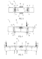
- the in 3 and 4 illustrated section of a Auszoomungsbeispiels a control panel 1. comprises two sensing elements 3, 5 and a tilting element 20 of a toggle switch with an embodiment of a switching mechanism according to the invention. Show here 3 and 4 in a solid embodiment, the starting position of the tilting element 20 and in dashed line an actuated switching position of the tilting element 20th Fig. 5 shows the tilting element 20 of the switching mechanism according to the invention for a toggle switch in different switching states. Again, the solid version shows the starting position of the tilting element 20 and the dashed versions each show an actuated switching position of the tilting element 20th
- the switching mechanism according to the invention for a toggle switch in the illustrated embodiment, the rotatably mounted tilting element 20 which has an actuating portion at each end 26, 28, at which a corresponding acting against a restoring force F 1 actuating force F 2 each have a corresponding tilting movement of the tilting element 20th about a tilt axis KA1, KA2 triggers.
- the rotatable mounting of the tilting element 20 is designed such that the tilting element 20 has two tilting axes KA1, KA2 at the ends 26, 28, one of which is effective as a function of the acting actuating force F 2 , wherein the tilting axis KA1, KA2 on the End 26, 28 of the tilting element 20 is effective, on which only the restoring force F 1 acts.
- a bearing element 22 is arranged substantially centrally between the two ends 26, 28 of the tilting element 20 and mounted in a guide 24, a rotary movement with a translational movement portion of the bearing element 22 in the direction of one end 26, 28 of the tilting element 20 against the restoring force F 1 acting actuating force F 2 allows.
- the bearing element 22 is designed, for example, as a continuous bearing shaft or as an integrally formed bearing journal, which are guided vertically in the guide 24 with sufficient freedom of movement to the required rotational movement with translational. Allow movement of the bearing member 22 for a corresponding switching operation.
- the vertical freedom of movement x of the bearing element 22 corresponds for example to at least half the actuation stroke h2 of the tilting element 20 and preferably moves in a range between 0.5 * h2 ⁇ x ⁇ 0.8 * h2, in particular between 0.5 * h2 ⁇ x ⁇ 0 , 7 * h2, wherein the ends 26, 28 of the tilting element 20 by the inventive design in the actuated state not over the adjacent Schartmaschine 3, 5 survive, or not be moved from the Aüsgangwolf upwards.
- By the described freedom of movement x can be prevented in an advantageous manner that at each end 26, 28 of the tilting element 20 at the same time a switching operation is triggered.
- a further actuation area is arranged substantially centrally on the tilting element.
- the Storage of the tilting element designed so that when a centrally acting on the actuating portion acting against the restoring force actuating force, the tilting element is translationally movable without rotational movement until both switch positions are confirmed.
- a holding device 21 is arranged at each end 26, 28 of the tilting element 20, which enable movements of the respective end 26, 28 of the tilting element 20 in predetermined ranges of motion and block outside the predetermined ranges of motion.
- the holding means 21 each comprise two latching hooks, which cooperate with corresponding recesses of the tilting element 20 so that the predetermined range of motion allows movement of the respective end 26, 28 of the tilting element 20 between the unactuated starting position and the corresponding actuated switching positions.
- the respective actuated switching position is given in the illustrated embodiment in each case by a stop 27, 29, to which the corresponding end 26, 28 of the tilting element 20 rests in the actuated switching state.
- the holding device 21 releases a translational movement portion of the actuated end 28 of the tilting element 20 in the direction of the switching position F 2 acting on one end 28 of the tilting element 20 and blocks a translatory movement portion of the other end 26 of the tilting element 20
- the restoring force F 1 moves the actuated end 28 of the tilting element 20 back from the corresponding switching position to the starting position and holds the tilting element 20 in the unactuated starting position.
- a further guide device 23, 25 is arranged at each end 26, 28 of the tilting element 20, which guide the movements of the respective end 26, 28 of the tilting element 20.
- the guide device comprises a guide element 25, preferably in the form of a rib, which is guided vertically in a corresponding guide 23, preferably in the form of a recess.
Landscapes
- Mechanical Control Devices (AREA)
- Rotary Switch, Piano Key Switch, And Lever Switch (AREA)
- Tumbler Switches (AREA)
Abstract
Description
- Die Erfindung betrifft einen Schaltmechanismus für einen Kippschalter der im Oberbegriff des Anspruchs 1 genannten Art, sowie einen zugehörigen Kippschalter mit einem solchen Schaltmechanismus und ein Bedienfeld mit einem solchen Kippschalter.
- In den Dokumenten
GB 2 342 229 A US 5,560,475 wird beispielsweise jeweils ein Schaltmechanismus für einen kippschalter in einem Bedienfeld für ein Kraftfahrzeug offenbart.Fig. 1. und Fig. 2 zeigen verschiedene schematische Darstellungen eines Ausschnitts eines solchen Bedienfelds, um das Prinzip des offenbarten Schaltmechanismus zu beschreiben. Wie ausFig. 1. und 2 ersichtlich ist, umfasst das Bedienfeld 1 im dargestellten Ausschnitt zwei Tastelemente 3, 5, zwischen welchen ein Kippelement 10 für einen Kippschalter drehbar gelagert angeordnet ist. Das Kippelement 10 weist an jedem Ende 16, 18 einen Betätigungsbereich auf, an welchem eine korrespondierende gegen eine Rückstellkraft F1 wirkende Betätigungskraft F2 jeweils eine entspreche Kippbewegung des Kippelements 10 um eine zentrale Kippachse KA auslöst. Zur Ausführung der Kippbewegung ist am Kippelement 10 in der Mitte zwischen den beiden Enden 16, 18 ein Lagerelement 12 angeordnet, welches beispielsweise als Kippwelle oder Lagerzapfen ausgeführt ist und in einem korrespondierenden Drehlager 14 drehbar gelagert ist. InFig. 2 ist ein betätigter Zustand des Kippelements 10 gestrichelt dargestellt, in welchem an einem Ende 18 des Kippelements 10 eine Betätigungskraft F2 gegen eine Rückstellkraft F1 wirkt. Wie ausFig. 2 weiter ersichtlich ist, steht das Kippelement 10 am nicht betätigten Ende 16 des Kippelements 12 um eine Höhe h1 Über die nichtbetätigten Tastelemente 3, 5 des Bedienfelds 1 über, wobei die Höhe h1 dem Betätigungshub des Kippelements 10 entspricht. - Aufgabe der Erfindung ist es, einen Schaltraechänismus für einen Kippschalter nach der im Oberbegriff des Anspruchs 1 genannten Art dahingehend weiterzuentwickeln, dass ein Überstand eines Kippelements im betätigten Zustand reduziert bzw. vermieden wird, sowie einen korrespondierenden Kippschalter und ein korrespondierendes Bedienfeld mit einem solchen Schaltmechanismus anzugeben.
- Diese Aufgabe wird erfindungsgemäß durch einen Schaltmeehanismus für einen Kippschalter mit den Merkmalen des Anspruchs 1 sowie durch einen Kippschalter mit den Merkmalen des Anspruchs 10 und durch ein Bedienfeld mit den Merkmalen des Anspruchs 11 gelöst. Weitere die Ausführungsformen der Erfindung in vorteilhafter Weise ausgestaltende Merkmale enthalten die Unteransprüche.
- Der mit der Erfindung erzielte Vorteil besteht darin, dass ein drehbar gelagertes Kippelement während der Betätigung und im betätigten Zustand nicht mehr über benachbarte Betätigungselemente übersteht.
- Der Grundgedanke der Erfindung basiert darauf, dass die drehbare Lagerung des Kippelements so ausgeführt ist, dass das Kippelement an den Enden zwei Kippachsen aufweist, von welchen in Abhängigkeit von einer wirkenden Betätigüngskraft eine wirksam ist, wobei die Kippachse an dem Ende des Kippelements wirksam ist, an welchem nur eine Rückstellkraft wirkt. Zudem weist das drehbar gelagerte Kippelement an jedem Ende einen Betätigungsbereich auf, an welchem die korrespondierende gegen die Rückstellkraft wirkende Betätigungskraft jeweils eine entspreche Kippbewegung des Kippelements um eine Kippachse auslöst.
- In vorteilhafter Ausgestaltung des erfindungsgemäßen Schaltmechanismus ist ein Lagerelement vorgesehen, welches im Mesentlichen mittig zwischen den beiden Enden des Kippelements angeordnet und in einer Führung gelagert ist. Hierbei ist das Lagerelement so in der Führung gelagerte dass eine relative Drehbewegung mit einem translatorischen Bewegungsanteil in Richtung der an einem Ende gegen die Rückstellkraft wirkende Betätigungskraft zwischen dem Lagerelement und der Führung ermöglicht ist. Das Lagerelement ist beispielsweise als Lagerwelle oder Lagerzapfen ausgeführt wobei die Lagerwelle in der Führung geführt ist, welche neben beiden Langseiten des Kippelements angeordnet ist. Bei einer Ausführung des Lagerelements als Lagerzapfen ist an jeder Längsseite des Kippelements ein solcher Lagerzapfen in einer korrespondierenden Führung gelagert. Durch den freigegebenen translatorischen Bewegungsanteil wird auch das mittig angeordnete Lagerelement in Richtung der Betätigungskraft bewegt, so dass die Kippachse an das entgegengesetzte Ende des Kippelements verschoben wird. Der translatorische Bewegungsanteil des Lagerelements entspricht etwa dem halben Betätigungshub des Kippelements.
- In weiterer vorteilhafter Ausgestaltung des erfindungsgemäßen Schaltmechanismus ist an jedem Ende des Kippelements eine Halteeinrichtung angeordnet, welche Bewegungen des jeweiligen Endes des Kippelements in vorgegebenen Bewegungsbereichen freigeben und außerhalb der vorgegebenen Bewegungsbereiche blockieren. Der vorgegebene Bewegungsbereich gibt beispielsweise eine Bewegung des jeweiligen Endes des Kippelements zwischen einer unbetätigten Ausgangsstellung und einer korrespondierenden betätigten Schaltstellung frei. Hierbei kann die jeweilige betätigte Schaltstellung vorzugsweise durch einen Anschlag vorgegeben werden.
- In weiterer vorteilhafter Ausgestaltung des erfindüngsgemaßen Schaltmechanismus ist die Halteeinrichtung so ausgeführt, dass in der Ausgangsstellung des Kippelements bei einer an einem Ende des Kippelements wirkenden Betätigungskraft ein translatorischer Bewegungsanteil des betätigten Endes des Kippelements in Richtung Schaltstellung freigegeben und ein translatorischer Bewegungsanteil des anderen Endes des Kippelements blockiert ist. Die Halteeinrichtung umfasst beispielsweise Rasthaken, welche in korrespondierende Aussparungen bzw. Fenster eingreifen, welche eine Länge aufweisen, welche dem Betätigungshub des Kippelements entspricht, und/oder durch korrespondierende Gegenhaken gehalten werden.
- In weiterer vorteilhafter Ausgestaltung des erfindungsgemäßen Schaltmechanismus bewegt die Rückstellkraft das betätigte Ende des Kippelements von der korrespondierenden Schaltstellung zurück in die Ausgangsstellung. Die Rückstellkraft wird beispielsweise von einem geeigneten Federelement, wie einer elastischen Membran, einer Feder usw. aufgebracht, welche in der Regel zwischen dem Kippelement und den betätigbaren elektrischen Kontakten der elektrischen Schaltkreise angeordnet ist.
- In weiterer vorteilhafter Ausgestaltung des erfindungsgemäßen Schältmechanismüs ist an jedem Ende des Kippelements eine zusätzliche Führungseinrichtung angeordnet, welche die Bewegungen des jeweiligen Endes des Kippelements führt und dadurch in vorteilhafter Weise ein Verkanten des Kippelements während der Betätigung verhindert.
- In weiterer vorteilhafter Ausgestaltung des erfindungsgemäßen Schaltmechanismus ist ein weiterer Betätigungsbereich im Wesentlichen mittig am Kippelement angeordnet. Hierbei ist die Lagerung des Kippelements so ausgeführt, dass bei einer am mittig angeordneten Betätigungsbereich gegen die Rückstellkraft wirkende Betätigungskraft das Kippelement ohne Drehbewegung translatorisch solange bewegbar ist, bis beide Schaltstellungen gleichseitig betätigt sind. Somit ergeben sich für den erfindungsgemäßen Schaltmechahismus eine unbetätigte Ausgangsstellung und drei verschiedene betätigte Schaltstellungen, wobei bei zwei betätigten Schaltstellungen jeweils nur ein Schaltvorgang ausgelöst wird und bei einer dritten betätigten Schaltstellung zwei Schaltvorgänge gleichzeitig ausgelöst werden.
- Der erfindungsgemäße Schaltmechanismus kann beispielsweise in einem Kippschalter mit einer unbetätigten Ausgangsstellung und mindestens zwei betätigten Schaltstellungen verwendet werden. Hierbei lösen zwei betätigte Schaltstellungen jeweils einen elektrischen Schaltvorgang aus und eine dritte betätigte Schaltstellung führt die beiden einzelnen Schaltvorgänge gleichzeitig aus.
- Des Weiteren wird ein Bedienfeld mit mindestens einem Kippschalter, der eine unbetätigte Ausgangsstellung und mindestens zwei betätigte Schaltstellungen aufweist, in welchen jeweils mindestens ein elektrischer Schaltvorgang ausgeführt ist, vorgeschlagen, wobei der mindestens eine Kippschalter einen erfindungsgemäßen Schaltmechanismus aufweist.
- Nachfolgend wird ein Ausführungsbeispiel der Erfindung anhand einer zeichnerischen Darstellung näher erläutert.
- In der Darstellung zeigt:
- Fig. 1
- eine schematische Draufsicht auf einen Ausschnitt eines herkömmlichen Bedienfelds mit zwei Tastelementen und einem Kippelement.
- Fig. 2
- eine schematische Seitenansicht des Ausschnitts eines herkömmlichen Bedienfelds aus
Fig. 1 . - Fig. 3
- eine schematische Draufsicht auf einen Ausschnitt eines Ausführungsbeispiels eines Bedienfelds mit zwei Tastelementen und einem Kippelement für ein Ausführungsbeispiel eines erfindungsgemäßen Schaltmechanismus.
- Fig. 4
- eine schematische Seitenansicht des Ausschnitts des Ausführungsbeispiels des erfindungsgemäßen Bedienfelds aus
Fig. 3 . - Fig. 5
- schematische Seitenansichten des Kippelements für den erfindungsgemäßen Schaltmechanismus für einen Kippschalter in verschiedenen Schaltzuständen.
- Der in
Fig. 3 und 4 dargestellte Ausschnitt eines Auszührungsbeispiels eines Bedienfelds 1. umfasst zwei Tastelemente 3, 5 und ein Kippelement 20 eines Kippschalters mit einem Ausführungsbeispiel eines erfindungsgemäßen Schaltmechanismus. Hierbei zeigenFig. 3 und 4 in durchgezogener Ausführung die Ausgangsstellung des Kippelements 20 und in gestrichelter Ausführung eine betätigte Schaltstellung des Kippelements 20.Fig. 5 zeigt das Kippelement 20 des erfindungsgemäßen Schaltmechanismus für einen Kippschalter in verschiedenen Schaltzuständen. Auch hier zeigt die durchgezogene Ausführung die Ausgangsstellung des Kippelements 20 und die gestrichelten Ausführungen zeigen jeweils eine betätigte Schaltstellung des Kippelements 20. - Wie aus
Fig. 3 bis 5 ersichtlich ist, umfasst der erfindungsgemäße Schaltmechanismus für einen Kippschalter im dargestellten Ausführungsbeispiel das drehbar gelagerte Kippelement 20, welches an jedem Ende 26, 28 einen Betätigungsbereich aufweist, an welchem eine korrespondierende gegen eine Rückstellkraft F1 wirkende Betätigungskraft F2 jeweils eine entsprechende Kippbewegung des Kippelements 20 um eine Kippachse KA1, KA2 auslöst. - Erfindungsgemäß ist die drehbare Lagerung des Kippelements 20 so ausgeführt, dass das Kippelement 20 an den Enden 26, 28 zwei Kippachsen KA1, KA2 aufweist, von welchen in Abhängigkeit von der wirkenden Betätigungskraft F2 eine wirksam ist, wobei die Kippachse KA1, KA2 an dem Ende 26, 28 des Kippelements 20 wirksam ist, an welchem nur die Rückstellkraft F1 wirkt.
- Wie aus
Fig. 3 und 4 ersichtlich ist, wirkt im dargestellten Ausführungsbeispiel die Betätigungskraft F2 am rechten Ende 28 des Kippelements 20 gegen die Rückstellkraft F1, so dass die Kippachse KA1 am linken Ende 26 des Kippelements 20 wirksam ist. Diese Schaltstellung des Kippelements 20 zeigt auch die Darstellung inFig. 5 , während die linke Darstellung inFig. 5 eine am linken Ende 26 des Kippelements 20 gegen die Rückstellkraft F1 wirkende Betätigungskraft F2 zeigt, so dass hier die Kippachse KA2 am rechten Ende 26 des Kippelements 20 wirksam ist. Die mittlere Darstellung inFig. 5 zeigt das Kippelement 20 in seiner unbetätigten Ausgangsstellung. - Wie aus
Fig. 3 bis 5 weiter ersichtlich ist, ist im Wesentlichen mittig zwischen den beiden Enden 26, 28 des Kippelements 20 ein Lagerelement 22 angeordnet und in einer Führung 24 gelagert, eine Drehbewegung mit einem translatörischen Bewegungsanteil des Lagerelements 22 in Richtung der an einem Ende 26, 28 des Kippelements 20 gegen die Rückstellkraft F1 wirkende Betätigungskraft F2 ermöglicht. Das Lagerelement 22 ist beispielsweise als durchgehende Lagerwelle oder als angeformte Lagerzapfen ausgeführt, welche in der Führung 24 vertikal mit einer ausreichenden Bewegungsfreiheit geführt sind, um die erforderliche Drehbewegung mit translatorischem. Bewegungsanteil des Lagerelements 22 für einen korrespondierenden Schaltvorgang zu ermöglichen. Die vertikale Bewegungsfreiheit x des Lagerelements 22 entspricht beispielsweise mindestens dem halben Betätigungshub h2 des Kippelements 20 und bewegt sich vorzugsweise in einem Bereich zwischen 0,5*h2 < x < 0,8*h2, insbesondere zwischen 0,5*h2 < x < 0,7*h2, wobei die Enden 26, 28 des Kippelements 20 durch die erfindungsgemäße Ausführung im betätigten Zustand nicht über die benachbarten Schartelemente 3, 5 überstehen, bzw. nicht von der Aüsgangstellung nach oben bewegt werden. Durch die beschriebene Bewegungsfreiheit x kann in vorteilhafter Weise verhindert werden, dass an jedem Ende 26, 28 des Kippelements 20 gleichzeitig ein Schaltvorgang ausgelöst wird. - Bei einer alternativen Ausgestaltung des erfindungsgemäßen Schaltmechanismus, ist ein weiterer Betätigungsbereich im Wesentlichen mittig am Kippelement angeordnet. Hierbei ist die Lagerung des Kippelements so ausgeführt, dass bei einer am mittig angeordneten Betätigungsbereich gegen die Rückstellkraft wirkende Betätigungskraft das Kippelement ohne Drehbewegung translatorisch solange bewegbar ist, bis beide Schaltstellungen bestätigt sind. Somit ergeben sich für den erfindungsgemäßen Schaltmechanismus eine unbetätigte Ausgangsstellung und drei verschiedene betätigte Schaltstellungen, wobei bei zwei betätigten Schaltstellungen jeweils nur ein Schaltvorgang ausgelöst werden kann und bei einer dritten betätigten Schaltstellung zwei Schaltvorgänge gleichzeitig ausgelöst werden können.
- Wie aus
Fig. 3 und 4 weiter ersichtlich ist, ist an jedem Enden 26, 28 des Kippelements 20 eine Halteeinrichtung 21 angeordnet, welche Bewegungen des jeweiligen Endes 26, 28 des Kippelements 20 in vorgegebenen Bewegungsbereichen freigeben und außerhalb der vorgegebenen Bewegungsbereiche blockieren. Im dargestellten Ausführungsbeispiel umfassen die Halteeinrichtungen 21 jeweils zwei Rasthaken, welche mit entsprechenden Aussparungen des Kippelements 20 so zusammenwirken, dass der vorgegebene Bewegungsbereich eine Bewegung des jeweiligen Endes 26, 28 des Kippelements 20 zwischen der unbetätigten Ausgangsstellung und den korrespondierenden betätigten Schaltstellungen ermöglicht. Die jeweilige betätigte Schaltstellung ist im dargestellten Ausführungsbeispiel jeweils durch einen Anschlag 27, 29 vorgegeben, an welchem das entsprechende Ende 26, 28 des Kippelements 20 im betätigten Schaltzustand anliegt. Somit gibt die Halteeinrichtung 21 in der Ausgangsstellung des Kippelements 20 bei einer an einem Ende 28 des Kippelements 20 wirkenden Betätigungskraft F2 einen translatorischen Bewegungsanteil des betätigten Endes 28 des Kippelements 20 in Richtung Schaltstellung frei und blockiert einen translatorischen Bewegungsanteil des anderen Endes 26 des Kippelements 20. Die Rückstellkraft F1 bewegt das betätigte Ende 28 des Kippelements 20 von der korrespondierenden Schaltstellung in die Ausgangsstellung zurück und hält das Kippelement 20 in der unbetätigten Ausgangstellung. - Zur Verbesserung der Betätigung ist an jedem Ende 26, 28 des Kippelements 20 eine weitere Führungseinrichtung 23, 25 angeordnet, welche die Bewegungen des jeweiligen Endes 26, 28 des Kippelements 20 führen. Hierbei umfasst die Führungseinrichtung ein Führungselement 25, vorzugsweise in Form einer Rippe, welches in einer korrespondierenden Führung 23, vorzugsweise in Form einer Aussparung, vertikal geführt ist.
Claims (12)
- Schaltmechanismus für einen Kippschalter mit einem drehbar gelagerten. Kippelement (20), welches an jedem Ende (26, 28) einen Betätigungsbereich aufweist, an welchem eine korrespondierende gegen eine Rückstellkraft (F1) wirkende Betätigungskraft (F2) jeweils eine entspreche Kippbewegung des Kippelements (20) um eine Kippachse (KA1, KA2) auslöst,
dadurch gekennzeichnet,
dass die drehbare Lagerung des Kippelements (20) so ausgeführt ist, dass das Kippelement (20) an den Enden. (26, 28) zwei Kippachsen (KA1, KA2) aufweist, von welchen in Abhängigkeit von der wirkenden Betätigungskraft (F2) eine wirksam ist, wobei die Kippachse (KA1, KA2) an dem Ende (26, 28) des Kippelements (20) wirksam ist, an welchem nur die Rückstellkraft (F1) wirkt. - Schaltmechanismus nach Anspruch 1,
gekennzeichnet durch
ein Lagerelement (22), welches im Wesentlichen mittig zwischen den beiden Enden (26, 28) des Kippelements (20) angeordnet und in einer Führung (24) gelagert ist, wobei das Lagerelement (22) so in der Führung (24) gelagert ist, dass eine relative Drehbewegung mit einem translatorischen Bewegungsanteil in Richtung der an einem Ende (26, 28) gegen die Rückstellkraft (F1) wirkende Betätigungskraft (F2) zwischen dem Lagerelement (22) und der Führung (24) ermöglicht ist. - Schaltmechanismus nach Anspruch 2,
dadurch gekennzeichnet, dass das Lagerelement (22) als Lagerwelle oder Lagerzapfen ausgeführt ist, welcher in der Führung (24) geführt ist. - Schaltmechanismus nach einem der Ansprüche 1 bis 3, dadurch gekennzeichnet,
dass an jedem Ende (26, 28) des Kippelements (20) eine Halteeinrichtung (21) angeordnet ist, welche Bewegungen des jeweiligen Endes (26, 28) des Kippelements (20) in vorgegebenen Bewegungsbereichen freigeben und außerhalb der vorgegebenen Bewegungsbereiche blockieren. - Schaltmechanismus nach Anspruch 4,
dadurch gekennzeichnet,
dass der vorgegebene Bewegungsbereich eine Bewegung des jeweiligen Endes (26, 28) des Kippelements (20) zwischen einer unbetätigten Ausgangsstellung und einer korrespondierenden betätigten Schaltstellung freigibt. - Schaltmechanismus nach Anspruch 5,
dadurch gekennzeichnet,
dass die jeweilige betätigte Schaltstellung durch einen Anschlag (27, 29) vorgegeben ist. - Schaltmechanismus nach einem der Ansprüche 4 bis 6, dadurch gekennzeichnet,
dass die Halteeinrichtung (21) in der Ausgangsstellung des Kippelements (20) bei einer an einem Ende (28) des Kippelements (20) wirkenden Betätigungskraft (F2) einen translatorischen Bewegungsanteil des betätigten Endes (28) des Kippelements (20) in Richtung Schaltstellung freigibt und einen translatorischen Bewegungsanteil des anderen Endes (26) des Kippelements (20) blockiert. - Schaltmechanismus nach einem der Ansprüche 4 bis 7, dadurch gekennzeichnet,
dass die Rückstellkraft (F1) das betätigte Ende (28) des Kippelements (20) von der korrespondierenden Schaltstellung in die Ausgangsstellung zurückbewegt. - Schaltmechanismus nach einem der Ansprüche 1 bis 8,
dadurch gekennzeichnet,
dass an jedem Ende (26, 28) des Kippelements (20) eine Führungseinrichtung (23, 25) angeordnet ist, welche die Bewegungen des jeweiligen Endes (26, 28) des Kippelements (20) führt. - Schaltmechanismus nach einem der Ansprüche 1 bis 9,
gekennzeichnet durch
einen weiteren im Wesentlichen mittig am Kippelement (20) angeordneten Betätigungsbereich, wobei die Lagerung des Kippelements so ausgeführt ist, dass bei einer am mittig angeordneten Betätigungsbereich gegen die Rückstellkraft (F1) wirkende Betätigungskraft (F2) das Kippelement ohne Drehbewegung translatorisch solange bewegbar ist, bis beide Schaltstellungen betätigt sind. - Kippschalter mit einer unbetätigten Ausgangsstellung und mindestens zwei betätigten Schaltstellungen, in welchen jeweils ein elektrischer Schaltvorgang ausgeführt ist, gekennzeichnet durch
einen Schaltmechanismus nach einem der Ansprüche 1 bis 9. - Bedienfeld mit mindestens einem Kippschalter, der eine unbetätigte Ausgangsstellung und mindestens zwei betätigte Schaltstellungen aufweist, in welchen jeweils ein elektrischer Schaltvorgang ausgeführt ist,
dadurch gekennzeichnet,
dass der mindestens eine Kippschalter einen Schaltmechanismus nach einem der Ansprüche 1 bis 10 aufweist.
Applications Claiming Priority (1)
| Application Number | Priority Date | Filing Date | Title |
|---|---|---|---|
| DE102010033218A DE102010033218A1 (de) | 2010-08-03 | 2010-08-03 | Schaltmechanismus für einen Kippschalter, Kippschalter und Bedienfeld |
Publications (3)
| Publication Number | Publication Date |
|---|---|
| EP2416337A2 true EP2416337A2 (de) | 2012-02-08 |
| EP2416337A3 EP2416337A3 (de) | 2012-05-02 |
| EP2416337B1 EP2416337B1 (de) | 2017-05-10 |
Family
ID=44503629
Family Applications (1)
| Application Number | Title | Priority Date | Filing Date |
|---|---|---|---|
| EP11176124.3A Active EP2416337B1 (de) | 2010-08-03 | 2011-08-01 | Schaltmechanismus für einen Kippschalter, Kippschalter und Bedienfeld |
Country Status (2)
| Country | Link |
|---|---|
| EP (1) | EP2416337B1 (de) |
| DE (1) | DE102010033218A1 (de) |
Families Citing this family (1)
| Publication number | Priority date | Publication date | Assignee | Title |
|---|---|---|---|---|
| WO2017172630A1 (en) | 2016-03-30 | 2017-10-05 | Shanghai Yanfeng Jinqiao Automotive Trim Systems Co. Ltd | Mechanism for console assembly |
Citations (2)
| Publication number | Priority date | Publication date | Assignee | Title |
|---|---|---|---|---|
| US5560475A (en) | 1994-12-14 | 1996-10-01 | Brundage; Douglas L. | Illuminated rocker buttons with light dams |
| GB2342229A (en) | 1998-08-13 | 2000-04-05 | Ford Motor Co | An automotive vehicle switch mechanism |
Family Cites Families (9)
| Publication number | Priority date | Publication date | Assignee | Title |
|---|---|---|---|---|
| DE3208559C2 (de) * | 1982-03-10 | 1985-12-05 | Preh, Elektrofeinmechanische Werke Jakob Preh Nachf. Gmbh & Co, 8740 Bad Neustadt | Tastatur |
| DE3719793A1 (de) * | 1987-06-13 | 1988-12-22 | Standard Elektrik Lorenz Ag | Elektrisches geraet mit einer wippentaste |
| JPH07282689A (ja) * | 1994-04-14 | 1995-10-27 | Alps Electric Co Ltd | 多方向入力スイッチ |
| US5536911A (en) * | 1995-06-30 | 1996-07-16 | Scientific-Atlanta, Inc. | Low force multi-direction multiple switch assembly |
| JP3951493B2 (ja) * | 1999-03-15 | 2007-08-01 | 松下電器産業株式会社 | 多方向操作スイッチおよびこれを用いた複合スイッチ |
| JP3758129B2 (ja) | 1999-10-15 | 2006-03-22 | 矢崎総業株式会社 | スイッチ装置 |
| JP3866022B2 (ja) * | 2000-07-31 | 2007-01-10 | アルプス電気株式会社 | 操作装置 |
| JP2004235059A (ja) * | 2003-01-31 | 2004-08-19 | Orion Denki Kk | 複合機器の記録媒体取出しボタンスイッチ |
| JP4113798B2 (ja) * | 2003-03-28 | 2008-07-09 | 株式会社東海理化電機製作所 | 2段操作スイッチ装置及び車両用ウインドウ駆動装置 |
-
2010
- 2010-08-03 DE DE102010033218A patent/DE102010033218A1/de not_active Withdrawn
-
2011
- 2011-08-01 EP EP11176124.3A patent/EP2416337B1/de active Active
Patent Citations (2)
| Publication number | Priority date | Publication date | Assignee | Title |
|---|---|---|---|---|
| US5560475A (en) | 1994-12-14 | 1996-10-01 | Brundage; Douglas L. | Illuminated rocker buttons with light dams |
| GB2342229A (en) | 1998-08-13 | 2000-04-05 | Ford Motor Co | An automotive vehicle switch mechanism |
Also Published As
| Publication number | Publication date |
|---|---|
| EP2416337A3 (de) | 2012-05-02 |
| EP2416337B1 (de) | 2017-05-10 |
| DE102010033218A1 (de) | 2012-02-09 |
Similar Documents
| Publication | Publication Date | Title |
|---|---|---|
| DE60217613T2 (de) | Schaltgerät | |
| DE3100862C2 (de) | Sicherheitsschalter | |
| EP2261445B1 (de) | Schloss, insbesondere Türschloss, mit verbesserter Schließmechanik | |
| DE102018205680A1 (de) | Wohnwagenfenster und Öffnungsmechanismus dafür | |
| WO2008122418A2 (de) | Neigungsversteller, insbesondere für die rückenlehne eines fahrzeugrücksitzes | |
| EP3433867B1 (de) | Kopplungsglied für ein elektrisches schaltgerät | |
| WO2017021383A1 (de) | Längsverstellvorrichtung für einen fahrzeugsitz | |
| DE102017206449A1 (de) | Wohnwagenfenster und Öffnungsmechanismus dafür | |
| EP2290672B1 (de) | Kontaktanordnung für elektromechanische Hilfsschalter | |
| EP1843377A1 (de) | Magnetantrieb für ein Relais | |
| DE102020129630B4 (de) | Eine auslöserschalterbaugruppe mit einem verriegelungsmechanismus | |
| EP2416337B1 (de) | Schaltmechanismus für einen Kippschalter, Kippschalter und Bedienfeld | |
| DE102009058719A1 (de) | Anordnung mit einem Raststößel | |
| WO2022033641A1 (de) | Linearantrieb und linearantriebsanordnung | |
| DE102010012908B4 (de) | Multifunktionsschalter | |
| DE4422475B4 (de) | Elektrischer Schalter | |
| EP0763247B1 (de) | Schnappschalter mit gerader bewegung des schaltstücks sowie schaltersystem hierzu | |
| EP1528870B1 (de) | Reinigungsvorrichtung für den scherkopf eines trockenrasierapparates | |
| DE102008035043B4 (de) | Mikroschalter | |
| EP1903586A1 (de) | Elektrisches Schaltgerät mit wenigstens einer Kontaktstelle | |
| DE102020204949A9 (de) | Sensor für eine Fahrzeugsicherheitseinrichtung | |
| DE2107804C3 (de) | Elektrischer Steuerschalter | |
| DE102013003575A1 (de) | Druck- und drehbetätigbares Bedienelement für ein Kraftfahrzeug | |
| DE102011007915B4 (de) | Elektromechanischer Schalter | |
| DE2717293A1 (de) | Elektromagnetisches relais mit zwangsgefuehrten kontakten |
Legal Events
| Date | Code | Title | Description |
|---|---|---|---|
| AK | Designated contracting states |
Kind code of ref document: A2 Designated state(s): AL AT BE BG CH CY CZ DE DK EE ES FI FR GB GR HR HU IE IS IT LI LT LU LV MC MK MT NL NO PL PT RO RS SE SI SK SM TR |
|
| AX | Request for extension of the european patent |
Extension state: BA ME |
|
| PUAI | Public reference made under article 153(3) epc to a published international application that has entered the european phase |
Free format text: ORIGINAL CODE: 0009012 |
|
| PUAL | Search report despatched |
Free format text: ORIGINAL CODE: 0009013 |
|
| AK | Designated contracting states |
Kind code of ref document: A3 Designated state(s): AL AT BE BG CH CY CZ DE DK EE ES FI FR GB GR HR HU IE IS IT LI LT LU LV MC MK MT NL NO PL PT RO RS SE SI SK SM TR |
|
| AX | Request for extension of the european patent |
Extension state: BA ME |
|
| RIC1 | Information provided on ipc code assigned before grant |
Ipc: H01H 25/04 20060101ALI20120327BHEP Ipc: H01H 23/14 20060101ALI20120327BHEP Ipc: H01H 23/16 20060101AFI20120327BHEP |
|
| 17P | Request for examination filed |
Effective date: 20121025 |
|
| GRAP | Despatch of communication of intention to grant a patent |
Free format text: ORIGINAL CODE: EPIDOSNIGR1 |
|
| RIC1 | Information provided on ipc code assigned before grant |
Ipc: H01H 23/14 20060101ALI20160725BHEP Ipc: H01H 25/04 20060101ALI20160725BHEP Ipc: H01H 23/16 20060101AFI20160725BHEP |
|
| INTG | Intention to grant announced |
Effective date: 20160811 |
|
| GRAS | Grant fee paid |
Free format text: ORIGINAL CODE: EPIDOSNIGR3 |
|
| GRAA | (expected) grant |
Free format text: ORIGINAL CODE: 0009210 |
|
| AK | Designated contracting states |
Kind code of ref document: B1 Designated state(s): AL AT BE BG CH CY CZ DE DK EE ES FI FR GB GR HR HU IE IS IT LI LT LU LV MC MK MT NL NO PL PT RO RS SE SI SK SM TR |
|
| REG | Reference to a national code |
Ref country code: GB Ref legal event code: FG4D Free format text: NOT ENGLISH |
|
| REG | Reference to a national code |
Ref country code: AT Ref legal event code: REF Ref document number: 893125 Country of ref document: AT Kind code of ref document: T Effective date: 20170515 Ref country code: CH Ref legal event code: EP |
|
| REG | Reference to a national code |
Ref country code: IE Ref legal event code: FG4D Free format text: LANGUAGE OF EP DOCUMENT: GERMAN |
|
| REG | Reference to a national code |
Ref country code: DE Ref legal event code: R096 Ref document number: 502011012191 Country of ref document: DE |
|
| REG | Reference to a national code |
Ref country code: FR Ref legal event code: PLFP Year of fee payment: 7 |
|
| REG | Reference to a national code |
Ref country code: NL Ref legal event code: MP Effective date: 20170510 |
|
| REG | Reference to a national code |
Ref country code: LT Ref legal event code: MG4D |
|
| PG25 | Lapsed in a contracting state [announced via postgrant information from national office to epo] |
Ref country code: FI Free format text: LAPSE BECAUSE OF FAILURE TO SUBMIT A TRANSLATION OF THE DESCRIPTION OR TO PAY THE FEE WITHIN THE PRESCRIBED TIME-LIMIT Effective date: 20170510 Ref country code: GR Free format text: LAPSE BECAUSE OF FAILURE TO SUBMIT A TRANSLATION OF THE DESCRIPTION OR TO PAY THE FEE WITHIN THE PRESCRIBED TIME-LIMIT Effective date: 20170811 Ref country code: ES Free format text: LAPSE BECAUSE OF FAILURE TO SUBMIT A TRANSLATION OF THE DESCRIPTION OR TO PAY THE FEE WITHIN THE PRESCRIBED TIME-LIMIT Effective date: 20170510 Ref country code: HR Free format text: LAPSE BECAUSE OF FAILURE TO SUBMIT A TRANSLATION OF THE DESCRIPTION OR TO PAY THE FEE WITHIN THE PRESCRIBED TIME-LIMIT Effective date: 20170510 Ref country code: NO Free format text: LAPSE BECAUSE OF FAILURE TO SUBMIT A TRANSLATION OF THE DESCRIPTION OR TO PAY THE FEE WITHIN THE PRESCRIBED TIME-LIMIT Effective date: 20170810 Ref country code: LT Free format text: LAPSE BECAUSE OF FAILURE TO SUBMIT A TRANSLATION OF THE DESCRIPTION OR TO PAY THE FEE WITHIN THE PRESCRIBED TIME-LIMIT Effective date: 20170510 |
|
| PG25 | Lapsed in a contracting state [announced via postgrant information from national office to epo] |
Ref country code: PL Free format text: LAPSE BECAUSE OF FAILURE TO SUBMIT A TRANSLATION OF THE DESCRIPTION OR TO PAY THE FEE WITHIN THE PRESCRIBED TIME-LIMIT Effective date: 20170510 Ref country code: BG Free format text: LAPSE BECAUSE OF FAILURE TO SUBMIT A TRANSLATION OF THE DESCRIPTION OR TO PAY THE FEE WITHIN THE PRESCRIBED TIME-LIMIT Effective date: 20170810 Ref country code: RS Free format text: LAPSE BECAUSE OF FAILURE TO SUBMIT A TRANSLATION OF THE DESCRIPTION OR TO PAY THE FEE WITHIN THE PRESCRIBED TIME-LIMIT Effective date: 20170510 Ref country code: LV Free format text: LAPSE BECAUSE OF FAILURE TO SUBMIT A TRANSLATION OF THE DESCRIPTION OR TO PAY THE FEE WITHIN THE PRESCRIBED TIME-LIMIT Effective date: 20170510 Ref country code: IS Free format text: LAPSE BECAUSE OF FAILURE TO SUBMIT A TRANSLATION OF THE DESCRIPTION OR TO PAY THE FEE WITHIN THE PRESCRIBED TIME-LIMIT Effective date: 20170910 Ref country code: SE Free format text: LAPSE BECAUSE OF FAILURE TO SUBMIT A TRANSLATION OF THE DESCRIPTION OR TO PAY THE FEE WITHIN THE PRESCRIBED TIME-LIMIT Effective date: 20170510 Ref country code: NL Free format text: LAPSE BECAUSE OF FAILURE TO SUBMIT A TRANSLATION OF THE DESCRIPTION OR TO PAY THE FEE WITHIN THE PRESCRIBED TIME-LIMIT Effective date: 20170510 |
|
| PG25 | Lapsed in a contracting state [announced via postgrant information from national office to epo] |
Ref country code: EE Free format text: LAPSE BECAUSE OF FAILURE TO SUBMIT A TRANSLATION OF THE DESCRIPTION OR TO PAY THE FEE WITHIN THE PRESCRIBED TIME-LIMIT Effective date: 20170510 Ref country code: SK Free format text: LAPSE BECAUSE OF FAILURE TO SUBMIT A TRANSLATION OF THE DESCRIPTION OR TO PAY THE FEE WITHIN THE PRESCRIBED TIME-LIMIT Effective date: 20170510 Ref country code: RO Free format text: LAPSE BECAUSE OF FAILURE TO SUBMIT A TRANSLATION OF THE DESCRIPTION OR TO PAY THE FEE WITHIN THE PRESCRIBED TIME-LIMIT Effective date: 20170510 Ref country code: CZ Free format text: LAPSE BECAUSE OF FAILURE TO SUBMIT A TRANSLATION OF THE DESCRIPTION OR TO PAY THE FEE WITHIN THE PRESCRIBED TIME-LIMIT Effective date: 20170510 Ref country code: DK Free format text: LAPSE BECAUSE OF FAILURE TO SUBMIT A TRANSLATION OF THE DESCRIPTION OR TO PAY THE FEE WITHIN THE PRESCRIBED TIME-LIMIT Effective date: 20170510 |
|
| REG | Reference to a national code |
Ref country code: DE Ref legal event code: R026 Ref document number: 502011012191 Country of ref document: DE |
|
| PLBI | Opposition filed |
Free format text: ORIGINAL CODE: 0009260 |
|
| PLAX | Notice of opposition and request to file observation + time limit sent |
Free format text: ORIGINAL CODE: EPIDOSNOBS2 |
|
| PG25 | Lapsed in a contracting state [announced via postgrant information from national office to epo] |
Ref country code: SM Free format text: LAPSE BECAUSE OF FAILURE TO SUBMIT A TRANSLATION OF THE DESCRIPTION OR TO PAY THE FEE WITHIN THE PRESCRIBED TIME-LIMIT Effective date: 20170510 Ref country code: IT Free format text: LAPSE BECAUSE OF FAILURE TO SUBMIT A TRANSLATION OF THE DESCRIPTION OR TO PAY THE FEE WITHIN THE PRESCRIBED TIME-LIMIT Effective date: 20170510 |
|
| 26 | Opposition filed |
Opponent name: PREH GMBH Effective date: 20180207 |
|
| REG | Reference to a national code |
Ref country code: CH Ref legal event code: PL |
|
| PG25 | Lapsed in a contracting state [announced via postgrant information from national office to epo] |
Ref country code: MC Free format text: LAPSE BECAUSE OF FAILURE TO SUBMIT A TRANSLATION OF THE DESCRIPTION OR TO PAY THE FEE WITHIN THE PRESCRIBED TIME-LIMIT Effective date: 20170510 |
|
| PG25 | Lapsed in a contracting state [announced via postgrant information from national office to epo] |
Ref country code: LI Free format text: LAPSE BECAUSE OF NON-PAYMENT OF DUE FEES Effective date: 20170831 Ref country code: CH Free format text: LAPSE BECAUSE OF NON-PAYMENT OF DUE FEES Effective date: 20170831 |
|
| REG | Reference to a national code |
Ref country code: IE Ref legal event code: MM4A |
|
| PG25 | Lapsed in a contracting state [announced via postgrant information from national office to epo] |
Ref country code: SI Free format text: LAPSE BECAUSE OF FAILURE TO SUBMIT A TRANSLATION OF THE DESCRIPTION OR TO PAY THE FEE WITHIN THE PRESCRIBED TIME-LIMIT Effective date: 20170510 |
|
| REG | Reference to a national code |
Ref country code: BE Ref legal event code: MM Effective date: 20170831 |
|
| PG25 | Lapsed in a contracting state [announced via postgrant information from national office to epo] |
Ref country code: LU Free format text: LAPSE BECAUSE OF NON-PAYMENT OF DUE FEES Effective date: 20170801 |
|
| PLBB | Reply of patent proprietor to notice(s) of opposition received |
Free format text: ORIGINAL CODE: EPIDOSNOBS3 |
|
| PG25 | Lapsed in a contracting state [announced via postgrant information from national office to epo] |
Ref country code: IE Free format text: LAPSE BECAUSE OF NON-PAYMENT OF DUE FEES Effective date: 20170801 |
|
| REG | Reference to a national code |
Ref country code: FR Ref legal event code: PLFP Year of fee payment: 8 |
|
| PG25 | Lapsed in a contracting state [announced via postgrant information from national office to epo] |
Ref country code: BE Free format text: LAPSE BECAUSE OF NON-PAYMENT OF DUE FEES Effective date: 20170831 |
|
| PG25 | Lapsed in a contracting state [announced via postgrant information from national office to epo] |
Ref country code: MT Free format text: LAPSE BECAUSE OF FAILURE TO SUBMIT A TRANSLATION OF THE DESCRIPTION OR TO PAY THE FEE WITHIN THE PRESCRIBED TIME-LIMIT Effective date: 20170510 |
|
| REG | Reference to a national code |
Ref country code: AT Ref legal event code: MM01 Ref document number: 893125 Country of ref document: AT Kind code of ref document: T Effective date: 20170801 |
|
| PG25 | Lapsed in a contracting state [announced via postgrant information from national office to epo] |
Ref country code: AT Free format text: LAPSE BECAUSE OF NON-PAYMENT OF DUE FEES Effective date: 20170801 |
|
| PG25 | Lapsed in a contracting state [announced via postgrant information from national office to epo] |
Ref country code: HU Free format text: LAPSE BECAUSE OF FAILURE TO SUBMIT A TRANSLATION OF THE DESCRIPTION OR TO PAY THE FEE WITHIN THE PRESCRIBED TIME-LIMIT; INVALID AB INITIO Effective date: 20110801 |
|
| PG25 | Lapsed in a contracting state [announced via postgrant information from national office to epo] |
Ref country code: CY Free format text: LAPSE BECAUSE OF NON-PAYMENT OF DUE FEES Effective date: 20170510 |
|
| PG25 | Lapsed in a contracting state [announced via postgrant information from national office to epo] |
Ref country code: MK Free format text: LAPSE BECAUSE OF FAILURE TO SUBMIT A TRANSLATION OF THE DESCRIPTION OR TO PAY THE FEE WITHIN THE PRESCRIBED TIME-LIMIT Effective date: 20170510 |
|
| PLCK | Communication despatched that opposition was rejected |
Free format text: ORIGINAL CODE: EPIDOSNREJ1 |
|
| REG | Reference to a national code |
Ref country code: DE Ref legal event code: R100 Ref document number: 502011012191 Country of ref document: DE |
|
| PG25 | Lapsed in a contracting state [announced via postgrant information from national office to epo] |
Ref country code: TR Free format text: LAPSE BECAUSE OF FAILURE TO SUBMIT A TRANSLATION OF THE DESCRIPTION OR TO PAY THE FEE WITHIN THE PRESCRIBED TIME-LIMIT Effective date: 20170510 |
|
| PG25 | Lapsed in a contracting state [announced via postgrant information from national office to epo] |
Ref country code: PT Free format text: LAPSE BECAUSE OF FAILURE TO SUBMIT A TRANSLATION OF THE DESCRIPTION OR TO PAY THE FEE WITHIN THE PRESCRIBED TIME-LIMIT Effective date: 20170510 |
|
| PLBN | Opposition rejected |
Free format text: ORIGINAL CODE: 0009273 |
|
| STAA | Information on the status of an ep patent application or granted ep patent |
Free format text: STATUS: OPPOSITION REJECTED |
|
| PG25 | Lapsed in a contracting state [announced via postgrant information from national office to epo] |
Ref country code: AL Free format text: LAPSE BECAUSE OF FAILURE TO SUBMIT A TRANSLATION OF THE DESCRIPTION OR TO PAY THE FEE WITHIN THE PRESCRIBED TIME-LIMIT Effective date: 20170510 |
|
| 27O | Opposition rejected |
Effective date: 20200228 |
|
| P01 | Opt-out of the competence of the unified patent court (upc) registered |
Effective date: 20230528 |
|
| PGFP | Annual fee paid to national office [announced via postgrant information from national office to epo] |
Ref country code: DE Payment date: 20250812 Year of fee payment: 15 |
|
| PGFP | Annual fee paid to national office [announced via postgrant information from national office to epo] |
Ref country code: GB Payment date: 20250826 Year of fee payment: 15 |
|
| PGFP | Annual fee paid to national office [announced via postgrant information from national office to epo] |
Ref country code: FR Payment date: 20250828 Year of fee payment: 15 |