EP2414721B1 - Längenvariable schutzabdeckung - Google Patents
Längenvariable schutzabdeckung Download PDFInfo
- Publication number
- EP2414721B1 EP2414721B1 EP10805695A EP10805695A EP2414721B1 EP 2414721 B1 EP2414721 B1 EP 2414721B1 EP 10805695 A EP10805695 A EP 10805695A EP 10805695 A EP10805695 A EP 10805695A EP 2414721 B1 EP2414721 B1 EP 2414721B1
- Authority
- EP
- European Patent Office
- Prior art keywords
- lamellae
- protective cover
- edge
- wiping
- length
- Prior art date
- Legal status (The legal status is an assumption and is not a legal conclusion. Google has not performed a legal analysis and makes no representation as to the accuracy of the status listed.)
- Active
Links
- 230000001681 protective effect Effects 0.000 title claims description 20
- 241000446313 Lamella Species 0.000 claims description 28
- 238000005452 bending Methods 0.000 claims description 7
- 230000008878 coupling Effects 0.000 claims description 4
- 238000010168 coupling process Methods 0.000 claims description 4
- 238000005859 coupling reaction Methods 0.000 claims description 4
- 239000004033 plastic Substances 0.000 claims description 2
- 239000002184 metal Substances 0.000 claims 1
- 238000007790 scraping Methods 0.000 description 11
- 230000003993 interaction Effects 0.000 description 4
- 230000035515 penetration Effects 0.000 description 3
- 230000015572 biosynthetic process Effects 0.000 description 2
- 238000010276 construction Methods 0.000 description 2
- 230000000694 effects Effects 0.000 description 2
- 238000005755 formation reaction Methods 0.000 description 2
- 239000002245 particle Substances 0.000 description 2
- 238000007789 sealing Methods 0.000 description 2
- 229910000639 Spring steel Inorganic materials 0.000 description 1
- 238000003754 machining Methods 0.000 description 1
- 238000004519 manufacturing process Methods 0.000 description 1
- 239000000463 material Substances 0.000 description 1
- 239000007769 metal material Substances 0.000 description 1
- 239000003351 stiffener Substances 0.000 description 1
- 230000007704 transition Effects 0.000 description 1
Images


Classifications
-
- F—MECHANICAL ENGINEERING; LIGHTING; HEATING; WEAPONS; BLASTING
- F16—ENGINEERING ELEMENTS AND UNITS; GENERAL MEASURES FOR PRODUCING AND MAINTAINING EFFECTIVE FUNCTIONING OF MACHINES OR INSTALLATIONS; THERMAL INSULATION IN GENERAL
- F16P—SAFETY DEVICES IN GENERAL; SAFETY DEVICES FOR PRESSES
- F16P3/00—Safety devices acting in conjunction with the control or operation of a machine; Control arrangements requiring the simultaneous use of two or more parts of the body
- F16P3/02—Screens or other safety members moving in synchronism with members which move to and fro
-
- B—PERFORMING OPERATIONS; TRANSPORTING
- B23—MACHINE TOOLS; METAL-WORKING NOT OTHERWISE PROVIDED FOR
- B23Q—DETAILS, COMPONENTS, OR ACCESSORIES FOR MACHINE TOOLS, e.g. ARRANGEMENTS FOR COPYING OR CONTROLLING; MACHINE TOOLS IN GENERAL CHARACTERISED BY THE CONSTRUCTION OF PARTICULAR DETAILS OR COMPONENTS; COMBINATIONS OR ASSOCIATIONS OF METAL-WORKING MACHINES, NOT DIRECTED TO A PARTICULAR RESULT
- B23Q11/00—Accessories fitted to machine tools for keeping tools or parts of the machine in good working condition or for cooling work; Safety devices specially combined with or arranged in, or specially adapted for use in connection with, machine tools
- B23Q11/08—Protective coverings for parts of machine tools; Splash guards
- B23Q11/0825—Relatively slidable coverings, e.g. telescopic
Definitions
- the present invention is concerned with a variable-length protective cover, which has a plurality of fins, which are connected on one longitudinal side in each case a strongly angled fastening edge, with which they are connected to the lamellae connecting coupling elements or with a bellows connecting the fins, and on its opposite longitudinal side each have a flat angled scraper edge, the edge rests on a respective adjacent lamella.
- Such protective covers in particular for parts of machine tools, have been known for some time with or without bellows, with both L-shaped embodiments, in which the fastening edges protrude only relatively short from the lamellar body, as well as embodiments with U-shaped lamellae, in which the fastening edge is formed by the web of the lamellar cross-section, to which the legs of the U-shaped cross section with a respective scraping edge at the free end join on both sides.
- a U-shaped lamella thus constitutes a lamella composed of two L-shaped lamellae, which are integrally connected to the attachment edge.
- the object of the invention is to improve a variable-length protective cover such that the penetration of particles and foreign bodies such. B. chips in workpiece machining, is significantly reduced.
- the object is achieved by a variable length protective cover of the type mentioned, in which the width of the wiper edge over the length of the lamella varies such that there is a convex profile of the edge of the wiper edge over its entire length.
- the curvature is formed to such an extent that the scraper edge disposed on an arched side of a blade rests in its central region even in the most extended state of the protective cover close to the substantially flat portion of the adjacent blade near the attachment edge.
- the convex curvature of the edge can extend over the entire length of the lamella, but it is also possible that the lamella has over its length a plurality of subsections in which a variation of the width of the wiping edge is provided.
- the lamella has kinks between these sections, so that a roof or in longitudinal section results in a polygonal shape.
- the lamella is bent once in the middle and has two sections laterally of the kink, in which the width of the wiper edge varies in a consistent manner or in different ways.
- Different configurations of the sections may be particularly advantageous in asymmetric slats, inclined mounting positions or the like.
- the two sections such as B. at a fold over a bending edge, materially connected or by a small, expedient manner z. B. be covered by overlapping covered joint.
- a convex course of the edge of the wiping edge can be achieved, for example, by having a constant radius over the length of the lamella or of a partial section.
- the convex curvature can also be achieved in that the edge of the wiper edge or the edge of the subsections of the wiper edge of the lamella describes a parabola, hyperbola or ellipse or follows another function.
- the lamellae can also be U-shaped, wherein the web of the U forms a stiffening edge acting on two sides and each of the two legs of the U has a scraping edge.
- metallic materials eg. As spring steel, or plastic.
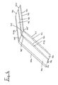
- a lamella 10 is shown, as it is used for the construction of variable length protective covers (not shown), wherein a plurality of successive lamellae 10 by means of a fastening edge 12 connecting coupling elements to them (not shown) or are arranged on a bellows.
- the attachment edge 12 is angled to the blade body 14 in the illustrated embodiment by approximately 80 °, wherein the inclination angle is achieved by a first bending line 16 with a very flat bending angle and a second bending line 18 with a stronger bending angle.
- a wiper edge 22 is arranged over a third bending line 20, which is inclined in the embodiment shown in an inclination angle of about 10 to 15 ° relative to the lamella base body 14.
- the wiping edge 22 has a width that is variable over the length of the lamella 10, so that an edge 24 of the wiping edge 22 describes a total of one radius or several radii merging into one another.
- the difference of the maximum width of the wiper edge 22 to the smallest width is small in relation to the length of the lamella and is usually in the single-digit percentage range of the lamella length.
- the radius need not be constant, it is also such variable radii along the length of the lamella conceivable that the edge 24 of the wiper edge 22, for example, describes a parabola, hyperbola or ellipse. Depending on the construction of the protective cover, the edge can also be non-steady points, d. H. Have peaks or notches, or rectilinear sections.
- Fig. 2 the interaction of the fins 10 is shown after the structure of the protective cover, again having been dispensed with the representation of a bellows or coupling elements.
- the edge 24 of the lamella 10 slides on the upper side of the lamellae main body 14 of a subsequent lamella, whereby by the embodiment of the lamellar edge 24, which is convex in the exemplary embodiment shown, itself on the largely flat region of the main body of the subsequent lamella 10, a good sealing effect against the ingress of foreign bodies can be achieved.
- a further embodiment of a blade 110 is shown, which is divided into two sections 111a, 111b.
- the individual sections 111a, b correspond in practice to the lamella 10 described above Fig. 1 and accordingly each have a fastening edge 112, a lamella base body 114 and a wiping edge 122.
- the sections 111a, 111b are connected by a kink 113 so that a roof-like configuration of the overall lamella 110 results.
- Such a lamellar formation may be advantageous, for example, in the case of large lamellae total lengths, but it is also possible for lamellas whose juxtaposed partial sections result in L-shaped or U-shaped protective covers and which accordingly also have additional sections. Also arched polygonal formations with a variety of sections are possible.
- the two sections have at their scraping edges in each case via convex edges 124, d. H. the edges 124 of the scraping edges 122 have different centers of their curvature, wherein in the region of the bend 113 a notch 115 between the edges 124 of the two sections 111a, b is present.
- Fig. 4 is the interaction of successive lamellae 110 with roof-shaped training to Fig. 3 shown.
- the edges 124 of the scraping edges 122 slide on the lamellae main bodies 114 of adjacent lamellae and thus ensure the sealing effect.
- the notch between the sections 111a, b in the region of the edges 124 is not disadvantageous since there also in the region of the lamellar base body 114 the corresponding kink 113 extends between the lamellae main bodies 114.
- the convex design of the edge 124 also promotes the removal of impinging foreign bodies towards the lateral edge of the protective cover, while in the case of straight edges of scraping edges, the foreign bodies can permanently accumulate on the lamella main bodies of the adjacent lamellae.
Landscapes
- Engineering & Computer Science (AREA)
- Mechanical Engineering (AREA)
- General Engineering & Computer Science (AREA)
- Auxiliary Devices For Machine Tools (AREA)
- Sealing Devices (AREA)
- Cleaning In General (AREA)
- Specific Sealing Or Ventilating Devices For Doors And Windows (AREA)
Description
- Die vorliegende Erfindung befasst sich mit einer längenvariablen Schutzabdeckung, die eine Vielzahl von Lamellen aufweist, die an einer Längsseite jeweils eine stark abgewinkelte Befestigungskante, mit welcher sie mit die Lamellen verbindenden Koppelelementen oder mit einem die Lamellen verbindenden Faltenbalg verbunden sind, und an ihrer gegenüberliegenden Längsseite jeweils eine flach abgewinkelte Abstreifkante aufweisen, deren Rand auf einer jeweils benachbarten Lamelle aufliegt.
- Derartige Schutzabdeckungen, insbesondere für Teile von Werkzeugmaschinen, sind mit oder ohne Faltenbalg bereits seit einiger Zeit bekannt, wobei sowohl L-förmige Ausführungsformen, bei welchen die Befestigungskanten nur relativ kurz von dem Lamellenkörper abstehen, als auch Ausführungsformen mit U-förmigen Lamellen bekannt sind, bei welchen die Befestigungskante durch den Steg des Lamellenquerschnitts gebildet ist, an den sich beidseitig die Schenkel des U-förmigen Querschnitts mit jeweils einer Abstreifkante am freien Ende anschließen. Eine U-förmige Lamelle stellt somit eine aus zwei L-förmigen Lamellen, die an der Befestigungskante einstückig verbunden sind, zusammengesetzte Lamelle dar.
- Ein Beispiel für eine derartige Schutzabdeckung mit U-förmigen Lamellen ist aus der
DE 103 08 024 A1 bekannt. Diese Schrift zeigt die übliche, über die Länge gleichmäßig breite Ausbildung der Abstreifkanten, die in der Regel um beispielsweise 10 bis 15°, ggf. aber auch mit stärkerer oder geringerer Neigung von dem Lamellenkörper abgewinkelt sind. Durch diese abgewinkelten Abstreifkanten ergibt sich eine elastisch nachgiebige Anlage, die dafür sorgen soll, dass Späne und andere Partikel den Behang nicht durchdringen können, sondern durch die Abstreifkanten abgestreift werden und beispielsweise in einen Sammelbehälter fallen. Ein weiteres Beispiel für Abstreiferkanten ist aus derDE 10 2004 055 714 A1 bekannt. Dort sind bei einer L-förmigen Lamelle im Bereich der Knickstelle Übergangsradien vorgesehen, wobei die Abstreiferkanten als geradlinige Gummilippen ausgebildet sind. Die mehrteilige Ausbildung verteuert die Lamellen und die Gummilippen können durch Späne schnell verschleißen. - Es hat sich gezeigt, dass mit geradlinig ausgebildeten Abstreifkanten oftmals nur ein unbefriedigender Schutz gegen das Eindringen von Spänen erreicht werden kann. Das liegt, abgesehen von aus dem Herstellungsverfahren resultierenden Einflussfaktoren, hauptsächlich daran, dass auf der einen Seite die stark abgewinkelte Befestigungskante als Aussteifung für eine weitgehend ebene Oberfläche des angrenzenden Bereichs des Lamellenkörpers sorgt, während auf der Seite der flach abgewinkelten Abstreifkante der Lamellenkörper sich infolge Materialelastizität aufwölben kann. Beim Auseinanderziehen und Zusammenschieben der Schutzabdeckung gleitet also eine Abstreifkante zeitweise auf einem ggf. aufgewölbten und anschließend auf dem weitgehend ebenen Oberflächenbereich der nachfolgenden Lamelle. Gleichmäßig breite Abstreifkanten an den selbst einer eventuellen Aufwölbung unterworfenen Seiten der Lamellen sind oft nicht in der Lage, in allen Bewegungsphasen in dichter Anlage an den unterschiedlichen Konturen der zu überstreichenden Oberflächen der Nachbarlamellen zu bleiben.
- Die Aufgabe der Erfindung besteht darin, eine längenvariable Schutzabdeckung derart zu verbessern, dass das Eindringen von Partikeln und Fremdkörpern, wie z. B. Spänen bei der Werkstückbearbeitung, deutlich vermindert wird.
- Erfindungsgemäß wird die Aufgabe durch eine längenvariable Schutzabdeckung der eingangs genannten Art gelöst, bei welcher die Breite der Abstreifkante über die Länge der Lamelle derart variiert, dass sich ein konvexer Verlauf des Randes der Abstreifkante über ihre gesamte Länge ergibt.
- Es hat sich gezeigt, dass durch diese Maßnahme das Eindringen von Fremdkörpern zwischen die aufeinander gleitenden Lamellen erheblich vermindert werden kann.
- Genauer gesagt ist die Wölbung in einem solchen Maße ausgebildet, dass die an einer aufgewölbten Seite einer Lamelle angeordnete Abstreifkante in ihrem mittleren Bereich auch noch in dem am weitesten ausgezogenen Zustand der Schutzabdeckung dicht an dem weitgehend ebenen Bereich der benachbarten Lamelle nahe deren Befestigungskante anliegt. Die konvexe Krümmung des Randes kann sich dabei über die gesamte Länge der Lamelle erstrecken, es ist aber auch möglich, dass die Lamelle über ihre Länge mehrere Teilabschnitte aufweist, in denen eine Variation der Breite der Abstreifkante vorgesehen ist.
- Bei der Untergliederung in Teilabschnitte ist es besonders von Vorteil, wenn die Lamelle zwischen diesen Teilabschnitten Knickstellen aufweist, so dass sich eine Dach- oder im Längsschnitt eine polygonale Form ergibt. Im einfachsten Fall ist die Lamelle mittig einmal geknickt und verfügt über zwei Teilabschnitte seitlich der Knickstelle, in denen die Breite der Abstreifkante in übereinstimmender Weise oder in unterschiedlicher Weise variiert. Unterschiedliche Ausbildungen der Teilabschnitte können insbesondere bei asymmetrischen Lamellen, geneigten Einbaulagen oder dergleichen von Vorteil sein. An der Knickstelle können die beiden Teilabschnitte, wie z. B. bei einer Abkantung über eine Biegekante, materialschlüssig verbunden oder durch eine kleine, zweckmäßiger Weise z. B. durch Überlappung überdeckte Fuge getrennt sein.
- Ein konvexer Verlauf des Randes der Abstreifkante kann beispielsweise dadurch erreicht werden, dass dieser über die Länge der Lamelle oder eines Teilabschnittes einen konstanten Radius aufweist. Die konvexe Krümmung kann aber auch dadurch erreicht werden, dass der Rand der Abstreifkante oder der Rand der Teilabschnitte der Abstreifkante der Lamelle eine Parabel, Hyperbel oder Ellipse beschreibt oder einer anderen Funktion folgt.
- Wie bereits erwähnt, können die Lamellen auch U-förmig ausgebildet sein, wobei der Steg des U eine nach zwei Seiten aussteifend wirkende Befestigungskante bildet und jeder der beiden Schenkel des U eine Abstreifkante aufweist. Zur Herstellung der Lamellen eignen sich metallische Werkstoffen, z. B. Federstahl, oder Kunststoff.
- Nachfolgend wird anhand der beigefügten Zeichnungen näher auf Ausführungsbeispiele der Erfindung eingegangen. Es zeigen:
- Fig. 1
- eine Schrägansicht einer Lamelle;
- Fig. 2
- schematisch das Zusammenwirken zweier aufeinander folgender Lamellen nach
Fig. 1 ; - Fig. 3
- eine dachförmige Lamelle;
- Fig. 4
- schematisch das Zusammenwirken von dachförmigen Lamellen nach
Fig. 3 . - In
Fig. 1 ist eine Lamelle 10 gezeigt, wie sie zum Aufbau von längenvariablen Schutzabdeckungen (nicht gezeigt) eingesetzt wird, wobei eine Vielzahl aufeinander folgender Lamellen 10 mittels einer Befestigungskante 12 an sie verbindenden Koppelelementen (nicht gezeigt) oder an einem Faltenbalg angeordnet sind. Die Befestigungskante 12 ist zu dem Lamellengrundkörper 14 bei dem gezeigten Ausführungsbeispiel um ungefähr 80° abgewinkelt, wobei der Neigungswinkel durch eine erste Biegelinie 16 mit einem sehr flachen Biegewinkel und eine zweite Biegelinie 18 mit einem stärkeren Biegewinkel erreicht wird. - Auf der der Befestigungskante 12 gegenüberliegenden Längsseite der Lamelle 10 ist über eine dritte Biegelinie 20 eine Abstreifkante 22 angeordnet, die bei dem gezeigten Ausführungsbeispiel in einem Neigungswinkel von ca. 10 bis 15° gegenüber dem Lamellengrundkörper 14 geneigt ist. Die Abstreifkante 22 besitzt eine über die Länge der Lamelle 10 variable Breite, so dass ein Rand 24 der Abstreifkante 22 insgesamt einen Radius oder mehrere ineinander übergehende Radien beschreibt. Die Differenz der maximalen Breite der Abstreifkante 22 zur kleinsten Breite ist klein im Verhältnis zur Länge der Lamelle und liegt in der Regel im einstelligen Prozentbereich der Lamellenlänge. Der Radius muss nicht konstant ausgeführt sein, es sind auch derart variable Radien über die Länge der Lamelle denkbar, dass der Rand 24 der Abstreifkante 22 beispielsweise eine Parabel, Hyperbel oder Ellipse beschreibt. Je nach Konstruktion der Schutzabdeckung kann der Rand zusätzlich auch nicht stetige Stellen, d. h. Spitzen oder Kerben, oder geradlinige Abschnitte aufweisen.
- In
Fig. 2 ist das Zusammenwirken der Lamellen 10 nach dem Aufbau der Schutzabdeckung dargestellt, wobei wiederum auf die Darstellung eines Faltenbalges oder von Koppelelementen verzichtet worden ist. Der Rand 24 der Lamelle 10 gleitet auf der Oberseite des Lamellengrundkörpers 14 einer nachfolgenden Lamelle, wobei durch die im gezeigten Ausführungsbeispiel konvexe Ausgestaltung des Lamellenrandes 24 selbst auf dem weitgehend ebenen Bereich des Grundkörpers der nachfolgenden Lamelle 10 eine gute Abdichtwirkung gegen das Eindringen von Fremdkörpern erreicht werden kann. - In
Fig. 3 ist eine weitere Ausführungsform einer Lamelle 110 gezeigt, die sich in zwei Teilabschnitte 111a, 111b gliedert. Die einzelnen Teilabschnitte 111a, b entsprechen praktisch der zuvor beschriebenen Lamelle 10 nachFig. 1 und verfügen entsprechend über jeweils eine Befestigungskante 112, einen Lamellengrundkörper 114 und eine Abstreifkante 122. Mittig sind die Teilabschnitte 111a, 111b über eine Knickstelle 113 verbunden, so dass sich eine dachartige Ausbildung der Gesamtlamelle 110 ergibt. Eine derartige Lamellenausbildung kann beispielsweise bei großen Lamellengesamtlängen von Vorteil sein, möglich sind aber auch Lamellen, deren aneinandergereihte Teilabschnitte L- oder U-förmige Schutzabdeckungen ergeben und die entsprechend auch noch weitere Teilabschnitte haben. Auch gewölbeartig polygonale Ausbildungen mit einer Vielzahl von Teilabschnitten sind möglich. - Bei der gezeigten Ausführungsform verfügen die beiden Teilabschnitte an ihren Abstreifkanten jeweils über konvexe Ränder 124, d. h. die Ränder 124 der Abstreifkanten 122 haben verschiedene Mittelpunkte ihrer Krümmung, wobei im Bereich der Knickstelle 113 eine Kerbe 115 zwischen den Rändern 124 der beiden Teilabschnitte 111a, b vorhanden ist.
- In
Fig. 4 ist das Zusammenwirken aufeinander folgender Lamellen 110 mit dachförmiger Ausbildung nachFig. 3 dargestellt. Wiederum gleiten die Ränder 124 der Abstreifkanten 122 auf den Lamellengrundkörpern 114 benachbarter Lamellen und stellen so die Dichtwirkung sicher. Die Kerbe zwischen den Teilabschnitten 111a, b im Bereich der Ränder 124 ist nicht von Nachteil, da dort auch im Bereich der Lamellengrundkörper 114 die entsprechende Knickstelle 113 zwischen den Lamellengrundkörpern 114 verläuft. - Zu erwähnen ist noch, dass die konvexe Gestaltung des Randes 124 auch den Abtransport von auftreffenden Fremdkörpern zum seitlichen Rand der Schutzabdeckung hin fördert, während bei geradlinigen Rändern von Abstreifkanten sich die Fremdkörper dauerhaft auf den Lamellengrundkörpern der benachbarten Lamellen ansammeln können.
Claims (7)
- Längenvariable Schutzabdeckung, die eine Vielzahl von Lamellen (10; 110) aufweist, die an einer Längsseite jeweils eine stark abgewinkelte Befestigungskante (12; 112), mit welcher sie mit die Lamellen verbindenden Koppelelementen oder mit einem die Lamellen verbindenden Faltenbalg verbunden sind, und an ihrer gegenüberliegenden Längsseite jeweils eine flach abgewinkelte Abstreifkante (22; 122) aufweisen, deren Rand (24; 124) auf einer jeweils benachbarten Lamelle (10; 110) aufliegt, dadurch gekennzeichnet, dass die Breite der Abstreifkanten (22; 124) über die Länge der Lamellen (10; 110) derart variiert, dass sich jeweils ein konvexer Verlauf des Randes (24; 124) der Abstreifkanten (22; 122) über ihre gesamte Länge ergibt.
- Längenvariable Schutzabdeckung nach Anspruch 1, dadurch gekennzeichnet, dass die Lamellen (110) über ihre Länge mehrere Teilabschnitte (111a, 111b) aufweisen, bei denen die Breite der Abstreifkanten (122) jeweils über die Länge der Teilabschnitte einen konvexen Verlauf besitzt.
- Längenvariable Schutzabdeckung nach Anspruch 2, dadurch gekennzeichnet, dass zwischen den Teilabschnitten (111a, 111b) der Lamellen (110) eine Knickstelle (113) mit einer Biegekante oder einer Trennfuge vorgesehen ist, so dass sich eine Dachform oder polygonale Form der Lamellen (110) ergibt.
- Längenvariable Schutzabdeckung nach einem der Ansprüche 2 bis 4, dadurch gekennzeichnet, dass die Ränder (24; 124) der Abstreifkanten (22; 124) über die Länge der Lamellen (110) bzw. die Längen der Teilabschnitte (111a, 111b) einen konstanten Radius aufweisen.
- Längenvariable Schutzabdeckung nach einem der Ansprüche 2 bis 4, dadurch gekennzeichnet, dass die Ränder (24; 124) der Abstreifkanten (22; 122) eine Parabel, Hyperbel oder Ellipse beschreiben oder einer sonstigen Funktion folgen.
- Längenvariable Schutzabdeckung nach einem der vorhergehenden Ansprüche, dadurch gekennzeichnet, dass die Lamellen (10; 110) U-förmig ausgebildet sind, wobei der Steg des U die Befestigungskante bildet und jeder der beiden Schenkel des U eine Abstreifkante aufweist.
- Längenvariable Schutzabdeckung nach einem der vorhergehenden Ansprüche, dadurch gekennzeichnet, dass die Lamellen aus Metall oder Kunststoff bestehen.
Applications Claiming Priority (2)
| Application Number | Priority Date | Filing Date | Title |
|---|---|---|---|
| DE102010004250A DE102010004250A1 (de) | 2010-01-08 | 2010-01-08 | Längenvariable Schutzabdeckung |
| PCT/EP2010/007949 WO2011082817A1 (de) | 2010-01-08 | 2010-12-28 | Längenvariable schutzabdeckung |
Publications (2)
| Publication Number | Publication Date |
|---|---|
| EP2414721A1 EP2414721A1 (de) | 2012-02-08 |
| EP2414721B1 true EP2414721B1 (de) | 2013-01-23 |
Family
ID=43857679
Family Applications (1)
| Application Number | Title | Priority Date | Filing Date |
|---|---|---|---|
| EP10805695A Active EP2414721B1 (de) | 2010-01-08 | 2010-12-28 | Längenvariable schutzabdeckung |
Country Status (4)
| Country | Link |
|---|---|
| EP (1) | EP2414721B1 (de) |
| CN (1) | CN102695904B (de) |
| DE (1) | DE102010004250A1 (de) |
| WO (1) | WO2011082817A1 (de) |
Families Citing this family (1)
| Publication number | Priority date | Publication date | Assignee | Title |
|---|---|---|---|---|
| JP5922554B2 (ja) * | 2012-10-31 | 2016-05-24 | 株式会社ジャバラ | 工作機械のテレスコピックカバー装置 |
Family Cites Families (7)
| Publication number | Priority date | Publication date | Assignee | Title |
|---|---|---|---|---|
| CN2193791Y (zh) * | 1994-04-27 | 1995-04-05 | 伟裕机械板金工业股份有限公司 | 伸缩护罩铁屑刮除装置 |
| DE20220812U1 (de) * | 2002-10-22 | 2004-04-15 | Möller Werke GmbH | Abdeckvorrichtung für Gleit- und Führungsbahnen von Maschinen |
| DE10308024A1 (de) | 2003-02-24 | 2004-09-02 | Hema Maschinen- Und Apparateschutz Gmbh | Längenvariable Schutzabdeckung |
| DE10344246A1 (de) * | 2003-09-23 | 2005-04-21 | Kabelschlepp Gmbh | Verfahren zur Ausbildung eines Abstreifers sowie Bausatz mit mehreren Bausatzelementen für an mehrere Anwendungsfälle anpassbaren Abstreifer |
| JP3944199B2 (ja) * | 2003-10-16 | 2007-07-11 | ファナック株式会社 | テレスコピックカバー |
| DE102004055714B4 (de) * | 2004-11-18 | 2008-07-24 | Eitec Führungsbahnschutz-Systeme Gmbh | Abstreifer |
| DE202007002839U1 (de) * | 2007-02-27 | 2007-05-10 | Hema Maschinen- Und Apparateschutz Gmbh | Lamellenabstreifer für eine längenveränderliche Lamellenabdeckung |
-
2010
- 2010-01-08 DE DE102010004250A patent/DE102010004250A1/de not_active Withdrawn
- 2010-12-28 EP EP10805695A patent/EP2414721B1/de active Active
- 2010-12-28 WO PCT/EP2010/007949 patent/WO2011082817A1/de not_active Ceased
- 2010-12-28 CN CN201080060410.5A patent/CN102695904B/zh active Active
Also Published As
| Publication number | Publication date |
|---|---|
| EP2414721A1 (de) | 2012-02-08 |
| DE102010004250A1 (de) | 2011-07-14 |
| CN102695904A (zh) | 2012-09-26 |
| WO2011082817A1 (de) | 2011-07-14 |
| CN102695904B (zh) | 2015-06-03 |
Similar Documents
| Publication | Publication Date | Title |
|---|---|---|
| EP2015971B1 (de) | Wischblatt | |
| DE102007017100A1 (de) | Verbindungselement und Schutzabdeckung | |
| DE102010061822A1 (de) | Wischblatt | |
| DE10007808B4 (de) | Wischblatt | |
| DE20220812U1 (de) | Abdeckvorrichtung für Gleit- und Führungsbahnen von Maschinen | |
| EP0016958B1 (de) | Rahmenprofil für ein Fenster, eine Tür od. dgl. | |
| DE3027083A1 (de) | Faltenbalg | |
| EP2243650B1 (de) | Blendenanordnung für ein KFZ-Fenster | |
| DE202008005170U1 (de) | Glasfalzeinlage | |
| WO2011082817A1 (de) | Längenvariable schutzabdeckung | |
| DE3600236A1 (de) | Wischblatt fuer kraftfahrzeuge | |
| DE102012004043B4 (de) | Einsteckbauteil, insbesondere Einsteckverbinder für Hohlprofile | |
| DE202009008981U1 (de) | Geschossfangvorrichtung | |
| EP1992779A2 (de) | Auszugsprofil für Fensterblende | |
| DE20303071U1 (de) | Faltenbalg | |
| DE102008028110A1 (de) | Abstreiferanordnung | |
| DE202008011357U1 (de) | Flexible Abdeckung | |
| DE202009006306U1 (de) | Faltenbalg | |
| EP1764184B1 (de) | Schutzabdeckung | |
| DE202009012234U1 (de) | Abstreifelement für Abstreifer von Bandförderanlagen, insbesondere für Trommelabstreifer, Trägerkörper und Klingenträger für ein solches Abstreifelement sowie mit wenigstens einem solchen Abstreifelement ausgestatteter Abstreifer für Bandförderanlagen, inbesondere Trommelabstreifer | |
| DE102011085819B4 (de) | Wischleiste | |
| DE10308096A1 (de) | Faltenbalg | |
| DE102011053991A1 (de) | Wischblatt zum Reinigen von Fahrzeugscheiben | |
| DE202009012189U1 (de) | Rollladenpanzer | |
| DE102007052357A1 (de) | Wischblatt |
Legal Events
| Date | Code | Title | Description |
|---|---|---|---|
| PUAI | Public reference made under article 153(3) epc to a published international application that has entered the european phase |
Free format text: ORIGINAL CODE: 0009012 |
|
| 17P | Request for examination filed |
Effective date: 20110622 |
|
| AK | Designated contracting states |
Kind code of ref document: A1 Designated state(s): AL AT BE BG CH CY CZ DE DK EE ES FI FR GB GR HR HU IE IS IT LI LT LU LV MC MK MT NL NO PL PT RO RS SE SI SK SM TR |
|
| GRAP | Despatch of communication of intention to grant a patent |
Free format text: ORIGINAL CODE: EPIDOSNIGR1 |
|
| GRAS | Grant fee paid |
Free format text: ORIGINAL CODE: EPIDOSNIGR3 |
|
| GRAA | (expected) grant |
Free format text: ORIGINAL CODE: 0009210 |
|
| AK | Designated contracting states |
Kind code of ref document: B1 Designated state(s): AL AT BE BG CH CY CZ DE DK EE ES FI FR GB GR HR HU IE IS IT LI LT LU LV MC MK MT NL NO PL PT RO RS SE SI SK SM TR |
|
| DAX | Request for extension of the european patent (deleted) | ||
| REG | Reference to a national code |
Ref country code: GB Ref legal event code: FG4D Free format text: NOT ENGLISH |
|
| REG | Reference to a national code |
Ref country code: CH Ref legal event code: EP |
|
| REG | Reference to a national code |
Ref country code: AT Ref legal event code: REF Ref document number: 595172 Country of ref document: AT Kind code of ref document: T Effective date: 20130215 Ref country code: CH Ref legal event code: EP |
|
| REG | Reference to a national code |
Ref country code: IE Ref legal event code: FG4D Free format text: LANGUAGE OF EP DOCUMENT: GERMAN |
|
| REG | Reference to a national code |
Ref country code: DE Ref legal event code: R096 Ref document number: 502010002237 Country of ref document: DE Effective date: 20130321 |
|
| REG | Reference to a national code |
Ref country code: LT Ref legal event code: MG4D |
|
| REG | Reference to a national code |
Ref country code: NL Ref legal event code: VDEP Effective date: 20130123 |
|
| PG25 | Lapsed in a contracting state [announced via postgrant information from national office to epo] |
Ref country code: SE Free format text: LAPSE BECAUSE OF FAILURE TO SUBMIT A TRANSLATION OF THE DESCRIPTION OR TO PAY THE FEE WITHIN THE PRESCRIBED TIME-LIMIT Effective date: 20130123 Ref country code: IS Free format text: LAPSE BECAUSE OF FAILURE TO SUBMIT A TRANSLATION OF THE DESCRIPTION OR TO PAY THE FEE WITHIN THE PRESCRIBED TIME-LIMIT Effective date: 20130523 Ref country code: LT Free format text: LAPSE BECAUSE OF FAILURE TO SUBMIT A TRANSLATION OF THE DESCRIPTION OR TO PAY THE FEE WITHIN THE PRESCRIBED TIME-LIMIT Effective date: 20130123 Ref country code: ES Free format text: LAPSE BECAUSE OF FAILURE TO SUBMIT A TRANSLATION OF THE DESCRIPTION OR TO PAY THE FEE WITHIN THE PRESCRIBED TIME-LIMIT Effective date: 20130504 Ref country code: NO Free format text: LAPSE BECAUSE OF FAILURE TO SUBMIT A TRANSLATION OF THE DESCRIPTION OR TO PAY THE FEE WITHIN THE PRESCRIBED TIME-LIMIT Effective date: 20130423 Ref country code: BG Free format text: LAPSE BECAUSE OF FAILURE TO SUBMIT A TRANSLATION OF THE DESCRIPTION OR TO PAY THE FEE WITHIN THE PRESCRIBED TIME-LIMIT Effective date: 20130423 |
|
| PG25 | Lapsed in a contracting state [announced via postgrant information from national office to epo] |
Ref country code: PT Free format text: LAPSE BECAUSE OF FAILURE TO SUBMIT A TRANSLATION OF THE DESCRIPTION OR TO PAY THE FEE WITHIN THE PRESCRIBED TIME-LIMIT Effective date: 20130523 Ref country code: LV Free format text: LAPSE BECAUSE OF FAILURE TO SUBMIT A TRANSLATION OF THE DESCRIPTION OR TO PAY THE FEE WITHIN THE PRESCRIBED TIME-LIMIT Effective date: 20130123 Ref country code: PL Free format text: LAPSE BECAUSE OF FAILURE TO SUBMIT A TRANSLATION OF THE DESCRIPTION OR TO PAY THE FEE WITHIN THE PRESCRIBED TIME-LIMIT Effective date: 20130123 Ref country code: SI Free format text: LAPSE BECAUSE OF FAILURE TO SUBMIT A TRANSLATION OF THE DESCRIPTION OR TO PAY THE FEE WITHIN THE PRESCRIBED TIME-LIMIT Effective date: 20130123 Ref country code: GR Free format text: LAPSE BECAUSE OF FAILURE TO SUBMIT A TRANSLATION OF THE DESCRIPTION OR TO PAY THE FEE WITHIN THE PRESCRIBED TIME-LIMIT Effective date: 20130424 Ref country code: FI Free format text: LAPSE BECAUSE OF FAILURE TO SUBMIT A TRANSLATION OF THE DESCRIPTION OR TO PAY THE FEE WITHIN THE PRESCRIBED TIME-LIMIT Effective date: 20130123 Ref country code: NL Free format text: LAPSE BECAUSE OF FAILURE TO SUBMIT A TRANSLATION OF THE DESCRIPTION OR TO PAY THE FEE WITHIN THE PRESCRIBED TIME-LIMIT Effective date: 20130123 |
|
| PG25 | Lapsed in a contracting state [announced via postgrant information from national office to epo] |
Ref country code: RS Free format text: LAPSE BECAUSE OF FAILURE TO SUBMIT A TRANSLATION OF THE DESCRIPTION OR TO PAY THE FEE WITHIN THE PRESCRIBED TIME-LIMIT Effective date: 20130123 Ref country code: HR Free format text: LAPSE BECAUSE OF FAILURE TO SUBMIT A TRANSLATION OF THE DESCRIPTION OR TO PAY THE FEE WITHIN THE PRESCRIBED TIME-LIMIT Effective date: 20130123 |
|
| PG25 | Lapsed in a contracting state [announced via postgrant information from national office to epo] |
Ref country code: CZ Free format text: LAPSE BECAUSE OF FAILURE TO SUBMIT A TRANSLATION OF THE DESCRIPTION OR TO PAY THE FEE WITHIN THE PRESCRIBED TIME-LIMIT Effective date: 20130123 Ref country code: SK Free format text: LAPSE BECAUSE OF FAILURE TO SUBMIT A TRANSLATION OF THE DESCRIPTION OR TO PAY THE FEE WITHIN THE PRESCRIBED TIME-LIMIT Effective date: 20130123 Ref country code: EE Free format text: LAPSE BECAUSE OF FAILURE TO SUBMIT A TRANSLATION OF THE DESCRIPTION OR TO PAY THE FEE WITHIN THE PRESCRIBED TIME-LIMIT Effective date: 20130123 Ref country code: RO Free format text: LAPSE BECAUSE OF FAILURE TO SUBMIT A TRANSLATION OF THE DESCRIPTION OR TO PAY THE FEE WITHIN THE PRESCRIBED TIME-LIMIT Effective date: 20130123 Ref country code: DK Free format text: LAPSE BECAUSE OF FAILURE TO SUBMIT A TRANSLATION OF THE DESCRIPTION OR TO PAY THE FEE WITHIN THE PRESCRIBED TIME-LIMIT Effective date: 20130123 |
|
| PG25 | Lapsed in a contracting state [announced via postgrant information from national office to epo] |
Ref country code: CY Free format text: LAPSE BECAUSE OF FAILURE TO SUBMIT A TRANSLATION OF THE DESCRIPTION OR TO PAY THE FEE WITHIN THE PRESCRIBED TIME-LIMIT Effective date: 20130123 |
|
| PLBE | No opposition filed within time limit |
Free format text: ORIGINAL CODE: 0009261 |
|
| STAA | Information on the status of an ep patent application or granted ep patent |
Free format text: STATUS: NO OPPOSITION FILED WITHIN TIME LIMIT |
|
| 26N | No opposition filed |
Effective date: 20131024 |
|
| REG | Reference to a national code |
Ref country code: DE Ref legal event code: R097 Ref document number: 502010002237 Country of ref document: DE Effective date: 20131024 |
|
| BERE | Be: lapsed |
Owner name: HEMA MASCHINEN- UND APPARATESCHUTZ G.M.B.H. Effective date: 20131231 |
|
| PG25 | Lapsed in a contracting state [announced via postgrant information from national office to epo] |
Ref country code: MC Free format text: LAPSE BECAUSE OF FAILURE TO SUBMIT A TRANSLATION OF THE DESCRIPTION OR TO PAY THE FEE WITHIN THE PRESCRIBED TIME-LIMIT Effective date: 20130123 |
|
| PG25 | Lapsed in a contracting state [announced via postgrant information from national office to epo] |
Ref country code: LU Free format text: LAPSE BECAUSE OF FAILURE TO SUBMIT A TRANSLATION OF THE DESCRIPTION OR TO PAY THE FEE WITHIN THE PRESCRIBED TIME-LIMIT Effective date: 20131228 |
|
| REG | Reference to a national code |
Ref country code: IE Ref legal event code: MM4A |
|
| REG | Reference to a national code |
Ref country code: FR Ref legal event code: ST Effective date: 20140829 |
|
| PG25 | Lapsed in a contracting state [announced via postgrant information from national office to epo] |
Ref country code: BE Free format text: LAPSE BECAUSE OF NON-PAYMENT OF DUE FEES Effective date: 20131231 Ref country code: IE Free format text: LAPSE BECAUSE OF NON-PAYMENT OF DUE FEES Effective date: 20131228 |
|
| PG25 | Lapsed in a contracting state [announced via postgrant information from national office to epo] |
Ref country code: FR Free format text: LAPSE BECAUSE OF NON-PAYMENT OF DUE FEES Effective date: 20131231 |
|
| PG25 | Lapsed in a contracting state [announced via postgrant information from national office to epo] |
Ref country code: SM Free format text: LAPSE BECAUSE OF FAILURE TO SUBMIT A TRANSLATION OF THE DESCRIPTION OR TO PAY THE FEE WITHIN THE PRESCRIBED TIME-LIMIT Effective date: 20130123 |
|
| PG25 | Lapsed in a contracting state [announced via postgrant information from national office to epo] |
Ref country code: TR Free format text: LAPSE BECAUSE OF FAILURE TO SUBMIT A TRANSLATION OF THE DESCRIPTION OR TO PAY THE FEE WITHIN THE PRESCRIBED TIME-LIMIT Effective date: 20130123 |
|
| PG25 | Lapsed in a contracting state [announced via postgrant information from national office to epo] |
Ref country code: HU Free format text: LAPSE BECAUSE OF FAILURE TO SUBMIT A TRANSLATION OF THE DESCRIPTION OR TO PAY THE FEE WITHIN THE PRESCRIBED TIME-LIMIT; INVALID AB INITIO Effective date: 20101228 Ref country code: MK Free format text: LAPSE BECAUSE OF FAILURE TO SUBMIT A TRANSLATION OF THE DESCRIPTION OR TO PAY THE FEE WITHIN THE PRESCRIBED TIME-LIMIT Effective date: 20130123 |
|
| REG | Reference to a national code |
Ref country code: CH Ref legal event code: PL |
|
| GBPC | Gb: european patent ceased through non-payment of renewal fee |
Effective date: 20141228 |
|
| PG25 | Lapsed in a contracting state [announced via postgrant information from national office to epo] |
Ref country code: MT Free format text: LAPSE BECAUSE OF FAILURE TO SUBMIT A TRANSLATION OF THE DESCRIPTION OR TO PAY THE FEE WITHIN THE PRESCRIBED TIME-LIMIT Effective date: 20130123 |
|
| PG25 | Lapsed in a contracting state [announced via postgrant information from national office to epo] |
Ref country code: CH Free format text: LAPSE BECAUSE OF NON-PAYMENT OF DUE FEES Effective date: 20141231 Ref country code: GB Free format text: LAPSE BECAUSE OF NON-PAYMENT OF DUE FEES Effective date: 20141228 Ref country code: LI Free format text: LAPSE BECAUSE OF NON-PAYMENT OF DUE FEES Effective date: 20141231 |
|
| REG | Reference to a national code |
Ref country code: DE Ref legal event code: R082 Ref document number: 502010002237 Country of ref document: DE Representative=s name: PATENTANWAELTE OLBRICHT, BUCHHOLD, KEULERTZ PA, DE |
|
| REG | Reference to a national code |
Ref country code: AT Ref legal event code: MM01 Ref document number: 595172 Country of ref document: AT Kind code of ref document: T Effective date: 20151228 |
|
| PG25 | Lapsed in a contracting state [announced via postgrant information from national office to epo] |
Ref country code: AT Free format text: LAPSE BECAUSE OF NON-PAYMENT OF DUE FEES Effective date: 20151228 |
|
| PG25 | Lapsed in a contracting state [announced via postgrant information from national office to epo] |
Ref country code: AL Free format text: LAPSE BECAUSE OF FAILURE TO SUBMIT A TRANSLATION OF THE DESCRIPTION OR TO PAY THE FEE WITHIN THE PRESCRIBED TIME-LIMIT Effective date: 20130123 |
|
| REG | Reference to a national code |
Ref country code: DE Ref legal event code: R082 Ref document number: 502010002237 Country of ref document: DE Representative=s name: BOULT WADE TENNANT LLP, DE |
|
| PGFP | Annual fee paid to national office [announced via postgrant information from national office to epo] |
Ref country code: DE Payment date: 20241128 Year of fee payment: 15 |
|
| PGFP | Annual fee paid to national office [announced via postgrant information from national office to epo] |
Ref country code: IT Payment date: 20241218 Year of fee payment: 15 |