EP2414689B1 - Zwischenrad- und lageranordnung und herstellungsverfahren dafür - Google Patents
Zwischenrad- und lageranordnung und herstellungsverfahren dafür Download PDFInfo
- Publication number
- EP2414689B1 EP2414689B1 EP09787692.4A EP09787692A EP2414689B1 EP 2414689 B1 EP2414689 B1 EP 2414689B1 EP 09787692 A EP09787692 A EP 09787692A EP 2414689 B1 EP2414689 B1 EP 2414689B1
- Authority
- EP
- European Patent Office
- Prior art keywords
- bearing ring
- spacers
- tubular
- radially
- ring
- Prior art date
- Legal status (The legal status is an assumption and is not a legal conclusion. Google has not performed a legal analysis and makes no representation as to the accuracy of the status listed.)
- Active
Links
Images


Classifications
-
- F—MECHANICAL ENGINEERING; LIGHTING; HEATING; WEAPONS; BLASTING
- F16—ENGINEERING ELEMENTS AND UNITS; GENERAL MEASURES FOR PRODUCING AND MAINTAINING EFFECTIVE FUNCTIONING OF MACHINES OR INSTALLATIONS; THERMAL INSULATION IN GENERAL
- F16C—SHAFTS; FLEXIBLE SHAFTS; ELEMENTS OR CRANKSHAFT MECHANISMS; ROTARY BODIES OTHER THAN GEARING ELEMENTS; BEARINGS
- F16C13/00—Rolls, drums, discs, or the like; Bearings or mountings therefor
- F16C13/006—Guiding rollers, wheels or the like, formed by or on the outer element of a single bearing or bearing unit, e.g. two adjacent bearings, whose ratio of length to diameter is generally less than one
-
- F—MECHANICAL ENGINEERING; LIGHTING; HEATING; WEAPONS; BLASTING
- F16—ENGINEERING ELEMENTS AND UNITS; GENERAL MEASURES FOR PRODUCING AND MAINTAINING EFFECTIVE FUNCTIONING OF MACHINES OR INSTALLATIONS; THERMAL INSULATION IN GENERAL
- F16C—SHAFTS; FLEXIBLE SHAFTS; ELEMENTS OR CRANKSHAFT MECHANISMS; ROTARY BODIES OTHER THAN GEARING ELEMENTS; BEARINGS
- F16C35/00—Rigid support of bearing units; Housings, e.g. caps, covers
- F16C35/04—Rigid support of bearing units; Housings, e.g. caps, covers in the case of ball or roller bearings
- F16C35/06—Mounting or dismounting of ball or roller bearings; Fixing them onto shaft or in housing
- F16C35/07—Fixing them on the shaft or housing with interposition of an element
- F16C35/073—Fixing them on the shaft or housing with interposition of an element between shaft and inner race ring
-
- F—MECHANICAL ENGINEERING; LIGHTING; HEATING; WEAPONS; BLASTING
- F16—ENGINEERING ELEMENTS AND UNITS; GENERAL MEASURES FOR PRODUCING AND MAINTAINING EFFECTIVE FUNCTIONING OF MACHINES OR INSTALLATIONS; THERMAL INSULATION IN GENERAL
- F16H—GEARING
- F16H55/00—Elements with teeth or friction surfaces for conveying motion; Worms, pulleys or sheaves for gearing mechanisms
- F16H55/32—Friction members
- F16H55/36—Pulleys
- F16H55/48—Pulleys manufactured exclusively or in part of non-metallic material, e.g. plastics
-
- F—MECHANICAL ENGINEERING; LIGHTING; HEATING; WEAPONS; BLASTING
- F16—ENGINEERING ELEMENTS AND UNITS; GENERAL MEASURES FOR PRODUCING AND MAINTAINING EFFECTIVE FUNCTIONING OF MACHINES OR INSTALLATIONS; THERMAL INSULATION IN GENERAL
- F16C—SHAFTS; FLEXIBLE SHAFTS; ELEMENTS OR CRANKSHAFT MECHANISMS; ROTARY BODIES OTHER THAN GEARING ELEMENTS; BEARINGS
- F16C19/00—Bearings with rolling contact, for exclusively rotary movement
- F16C19/02—Bearings with rolling contact, for exclusively rotary movement with bearing balls essentially of the same size in one or more circular rows
- F16C19/04—Bearings with rolling contact, for exclusively rotary movement with bearing balls essentially of the same size in one or more circular rows for radial load mainly
- F16C19/06—Bearings with rolling contact, for exclusively rotary movement with bearing balls essentially of the same size in one or more circular rows for radial load mainly with a single row or balls
-
- F—MECHANICAL ENGINEERING; LIGHTING; HEATING; WEAPONS; BLASTING
- F16—ENGINEERING ELEMENTS AND UNITS; GENERAL MEASURES FOR PRODUCING AND MAINTAINING EFFECTIVE FUNCTIONING OF MACHINES OR INSTALLATIONS; THERMAL INSULATION IN GENERAL
- F16C—SHAFTS; FLEXIBLE SHAFTS; ELEMENTS OR CRANKSHAFT MECHANISMS; ROTARY BODIES OTHER THAN GEARING ELEMENTS; BEARINGS
- F16C2361/00—Apparatus or articles in engineering in general
- F16C2361/63—Gears with belts and pulleys
-
- F—MECHANICAL ENGINEERING; LIGHTING; HEATING; WEAPONS; BLASTING
- F16—ENGINEERING ELEMENTS AND UNITS; GENERAL MEASURES FOR PRODUCING AND MAINTAINING EFFECTIVE FUNCTIONING OF MACHINES OR INSTALLATIONS; THERMAL INSULATION IN GENERAL
- F16H—GEARING
- F16H7/00—Gearings for conveying rotary motion by endless flexible members
- F16H7/08—Means for varying tension of belts, ropes, or chains
- F16H2007/0863—Finally actuated members, e.g. constructional details thereof
- F16H2007/0865—Pulleys
-
- Y—GENERAL TAGGING OF NEW TECHNOLOGICAL DEVELOPMENTS; GENERAL TAGGING OF CROSS-SECTIONAL TECHNOLOGIES SPANNING OVER SEVERAL SECTIONS OF THE IPC; TECHNICAL SUBJECTS COVERED BY FORMER USPC CROSS-REFERENCE ART COLLECTIONS [XRACs] AND DIGESTS
- Y10—TECHNICAL SUBJECTS COVERED BY FORMER USPC
- Y10T—TECHNICAL SUBJECTS COVERED BY FORMER US CLASSIFICATION
- Y10T29/00—Metal working
- Y10T29/49—Method of mechanical manufacture
- Y10T29/49453—Pulley making
- Y10T29/49455—Assembly
- Y10T29/49456—Assembly with shaping
Landscapes
- Engineering & Computer Science (AREA)
- General Engineering & Computer Science (AREA)
- Mechanical Engineering (AREA)
- Manufacturing & Machinery (AREA)
- Mounting Of Bearings Or Others (AREA)
Claims (10)
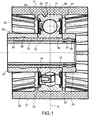
- Leitrollen- und Lageranordnung, die Folgendes umfasst:- eine Lagereinheit (10) mit einem radial äußeren Ring (11) und einem radial inneren Ring (12); und- einen äußeren Radkörper (20) aus Kunststoff, der auf den äußeren Lageraußenring (11) spritzgegossen wurde, und eine zylindrische Außenoberfläche (21) besitzt, die ausgelegt ist, um mit einem Antriebsriemen in Eingriff zu sein;die Anordnung ferner zwei rohrförmige Abstandshalter (31, 32) aus starrem Material umfasst, die axial auf den Lagerinnenring (12) ausgerichtet sind und an entsprechenden radial verlaufenden, axial gegenüberliegenden Seiten (14, 15) des Lagerinnenrings (12) anliegen;
dadurch gekennzeichnet, dass die Lageranordnung eine Hülseneinheit (30), die die Abstandshalter enthält und in den Lagerinnenring (12) eingebaut ist, als einen zentralen rohrförmigen Kern (33) aus Kunststoff, der in radial inneren zylindrischen Oberflächen (16, 34, 35) sowohl des Lagerinnenrings (12) als auch der zwei rohrförmigen Abstandshalter (31, 32) spritzgegossen wurde und axial in deren Richtung verläuft, umfasst. - Anordnung nach Anspruch 1, dadurch gekennzeichnet, dass die zwei Abstandshalter (31, 32), die sich an gegenüberliegenden Seiten des inneren Lagerrings (12) befinden, dieselbe axiale Länge besitzen.
- Anordnung nach Anspruch 2, dadurch gekennzeichnet, dass sich die zwei Abstandshalter (31, 32) axialsymmetrisch in Bezug auf eine Mittelebene (P) der Lagereinheit (10) befinden.
- Anordnung nach Anspruch 1, dadurch gekennzeichnet, dass die zwei Abstandshalter (31, 32), die sich an gegenüberliegenden Seiten des inneren Lagerrings (12) befinden, verschiedene axiale Längen besitzen und axialsymmetrisch in Bezug auf eine Mittelebene (P) der Lagereinheit (10) sind.
- Anordnung nach einem der vorhergehenden Ansprüche, dadurch gekennzeichnet, dass eine Aussparung (36, 37) in den radial inneren zylindrischen Oberflächen (34, 35) des einen oder der mehreren rohrförmigen Abstandshalter (31, 32) gebildet ist, wobei das Spritzgießen des Kunststoffs, der den zentralen Kern (33) bildet, Plastiküberstände ergibt, die komplementär zu der Aussparung sind und dadurch das mechanische gegenseitige Verriegeln der/des Abstandshalter(s) (31, 32) und des Plastikkerns (33) verbessern.
- Anordnung nach einem der vorhergehenden Ansprüche, dadurch gekennzeichnet, dass die rohrförmigen Abstandshalter (31, 32) aus Metall gebildet sind.
- Anordnung nach einem der vorhergehenden Ansprüche, dadurch gekennzeichnet, dass eine oder mehrere axiale Nuten (40) von dem inneren zylindrischen Hohlraum (41) des rohrförmigen Kerns (33) radial nach außen verlaufend gebildet sind, wobei die axialen Nuten axial derart verlaufen, dass sie Abschnitte (17) der radial inneren zylindrischen Oberfläche (16) des inneren Lagerrings (12) unabgedeckt lassen.
- Anordnung nach Anspruch 7, dadurch gekennzeichnet, dass mindestens ein rohrförmiger Abstandshalter (31, 32), der einen Abschnitt des Kerns (33) mit der einen oder den mehreren axialen Nuten (40) umgibt, eine innere zylindrische Oberfläche (34) besitzt, deren Durchmesser größer als der Durchmesser der inneren zylindrischen Oberfläche (16) des inneren Lagerrings (12) ist, wobei der Kunststoff (42) des Kerns die innere zylindrische Oberfläche des mindestens einen Abstandshalters auch dort abdeckt, wo die eine oder die mehreren axialen Nuten gebildet sind.
- Verfahren für das Herstellen einer Leitrollen- und Lageranordnung, wobei das Verfahren die folgenden Schritte umfasst:a) Vormontieren einer Lagereinheit (10), die einen radial äußeren Ring (11) und einen radial inneren Ring (12) besitzt;b) Anordnen von zwei rohrförmigen Abstandshaltern (31, 32) aus starrem Material, die axial auf den Lagerinnenring (12) ausgerichtet sind und an entsprechenden radial verlaufenden, axial gegenüberliegenden Seiten (14, 15) des Lagerinnenrings (12) anliegen;c1) Spritzgießen eines äußeren Radkörpers (20) aus Kunststoff auf den äußeren Lageraußenring (11), um eine zylindrische Außenoberfläche (21) bereitzustellen, die ausgelegt ist, um mit einem Antriebsriemen in Eingriff zu sein;c2) Spritzgießen eines zentralen rohrförmigen Kerns (33) aus Kunststoff in radial innere zylindrische Oberflächen (16, 34, 35) sowohl des Lagerinnenrings als auch der zwei rohrförmigen Abstandshalter, wodurch eine Hülseneinheit (30), die in den Lagerinnenring eingebaut ist, gebildet wird, wobei die Hülseneinheit die zwei rohrförmigen Abstandshalter (31, 32) und den rohrförmigen Kern (33), der axial in Richtung der inneren zylindrischen Oberflächen verläuft, enthält.
- Verfahren nach Anspruch 9, wobei die Formungsschritte c1) und c2) gleichzeitig erfolgen.
Applications Claiming Priority (1)
| Application Number | Priority Date | Filing Date | Title |
|---|---|---|---|
| PCT/IT2009/000141 WO2010113195A1 (en) | 2009-04-03 | 2009-04-03 | An idler and bearing assembly and a method of manufacturing same |
Publications (2)
| Publication Number | Publication Date |
|---|---|
| EP2414689A1 EP2414689A1 (de) | 2012-02-08 |
| EP2414689B1 true EP2414689B1 (de) | 2018-09-19 |
Family
ID=41382170
Family Applications (1)
| Application Number | Title | Priority Date | Filing Date |
|---|---|---|---|
| EP09787692.4A Active EP2414689B1 (de) | 2009-04-03 | 2009-04-03 | Zwischenrad- und lageranordnung und herstellungsverfahren dafür |
Country Status (4)
| Country | Link |
|---|---|
| US (1) | US9206838B2 (de) |
| EP (1) | EP2414689B1 (de) |
| CN (1) | CN102365468B (de) |
| WO (1) | WO2010113195A1 (de) |
Families Citing this family (21)
| Publication number | Priority date | Publication date | Assignee | Title |
|---|---|---|---|---|
| EP2687737A1 (de) * | 2012-07-20 | 2014-01-22 | Aktiebolaget SKF | Walzeneinheit mit einem Lager und einem Befestigungselement sowie Herstellungsverfahren dafür |
| DE102013102638A1 (de) * | 2013-03-14 | 2014-09-18 | Valeo Systèmes d'Essuyage | Welle, Wellenanordnung, Verfahren zum axialen Befestigen einer Lagereinrichtung auf einer Welle sowie Scheibenwischermotor |
| FR3006711B1 (fr) * | 2013-06-07 | 2015-06-05 | Skf Ab | Systeme d'entrainement de pompe a eau et procede de montage |
| EP3025998A1 (de) * | 2014-11-25 | 2016-06-01 | Inventio AG | Rolle einer Aufzugsanlage |
| US9845860B2 (en) * | 2015-07-20 | 2017-12-19 | Dayco Ip Holdings, Llc | Retaining clamp for molded plastics |
| EP3135957B1 (de) * | 2015-08-26 | 2020-04-29 | Aktiebolaget SKF | Riemenscheibenvorrichtung mit haltestopfen |
| DE102017223317A1 (de) * | 2017-12-20 | 2019-06-27 | Aktiebolaget Skf | Riemenscheibenvorrichtung, insbesondere für eine Spannrolle oder Laufrolle |
| FR3078758B1 (fr) * | 2018-03-06 | 2020-04-03 | Aktiebolaget Skf | Dispositif de poulie pour galet tendeur ou enrouleur |
| FR3078759B1 (fr) | 2018-03-06 | 2020-02-28 | Aktiebolaget Skf | Dispositif de poulie pour galet tendeur ou enrouleur |
| FR3079586B1 (fr) * | 2018-04-03 | 2020-04-03 | Aktiebolaget Skf | Dispositif de poulie pour galet tendeur ou enrouleur |
| FR3079584A1 (fr) * | 2018-04-03 | 2019-10-04 | Aktiebolaget Skf | Dispositif de poulie pour galet tendeur ou enrouleur |
| FR3079582B1 (fr) * | 2018-04-03 | 2020-04-03 | Aktiebolaget Skf | Dispositif de poulie pour galet tendeur ou enrouleur |
| FR3079583B1 (fr) * | 2018-04-03 | 2020-03-06 | Aktiebolaget Skf | Dispositif de poulie pour galet tendeur ou enrouleur |
| FR3080422B1 (fr) * | 2018-04-19 | 2020-04-03 | Aktiebolaget Skf | Dispositif de poulie pour galet tendeur ou enrouleur |
| FR3082908B1 (fr) * | 2018-06-26 | 2020-06-19 | Aktiebolaget Skf | Dispositif de poulie pour galet tendeur ou enrouleur |
| US11046514B2 (en) * | 2018-08-31 | 2021-06-29 | Intelligrated Headquarters, Llc | Carriage lift assembly for storage handling and article retrieval |
| CN109454990A (zh) * | 2018-12-26 | 2019-03-12 | 苏州斯莱克精密设备股份有限公司 | 用于浮动支撑金属空心体的新型芯棒结构 |
| CN109454989A (zh) * | 2018-12-26 | 2019-03-12 | 苏州斯莱克精密设备股份有限公司 | 用于浮动支撑金属空心体的芯棒结构 |
| US11261062B2 (en) | 2019-05-03 | 2022-03-01 | Otis Elevator Company | Modular sheave unit |
| FR3098875B1 (fr) * | 2019-07-18 | 2021-10-15 | Skf Svenska Kullagerfab Ab | Dispositif de poulie |
| US11192399B2 (en) * | 2019-11-06 | 2021-12-07 | Peer Bearing Company | Caster hub |
Citations (2)
| Publication number | Priority date | Publication date | Assignee | Title |
|---|---|---|---|---|
| US20040041462A1 (en) * | 2002-08-29 | 2004-03-04 | Hicks E. David | Cart wheel with molded bearing components |
| FR2923281A1 (fr) * | 2007-11-06 | 2009-05-08 | Skf Ab | Dispositif de galet tendeur ou enrouleur |
Family Cites Families (6)
| Publication number | Priority date | Publication date | Assignee | Title |
|---|---|---|---|---|
| NL172525C (nl) * | 1974-06-17 | 1983-09-16 | Skf Ind Trading & Dev | Wiel met lagerafdichting en sluitkap van de naaf. |
| US4917655A (en) * | 1989-03-01 | 1990-04-17 | Ina Bearing Co., Inc. | Self adjusting timing belt tensioner |
| DE29720776U1 (de) | 1997-11-22 | 1998-01-15 | Skf Gmbh | Befestigungsvorrichtung für Riemenrollen |
| DE29805581U1 (de) * | 1998-03-27 | 1998-05-28 | Skf Gmbh | Laufrolle |
| FR2794823B1 (fr) * | 1999-06-14 | 2001-08-10 | Skf France | Dispositif de fixation pour galet a roulement et galet a roulement comportant un tel dispositif |
| US20070065063A1 (en) * | 2005-04-25 | 2007-03-22 | Hsien Mo Lin | Rotary device having laterally movable axle |
-
2009
- 2009-04-03 WO PCT/IT2009/000141 patent/WO2010113195A1/en active Application Filing
- 2009-04-03 CN CN200980158549.0A patent/CN102365468B/zh active Active
- 2009-04-03 EP EP09787692.4A patent/EP2414689B1/de active Active
- 2009-04-03 US US13/262,164 patent/US9206838B2/en active Active
Patent Citations (3)
| Publication number | Priority date | Publication date | Assignee | Title |
|---|---|---|---|---|
| US20040041462A1 (en) * | 2002-08-29 | 2004-03-04 | Hicks E. David | Cart wheel with molded bearing components |
| FR2923281A1 (fr) * | 2007-11-06 | 2009-05-08 | Skf Ab | Dispositif de galet tendeur ou enrouleur |
| EP2217423A1 (de) * | 2007-11-06 | 2010-08-18 | Aktiebolaget SKF | Spannung einer roll- oder wicklungsvorrichtung |
Also Published As
| Publication number | Publication date |
|---|---|
| WO2010113195A1 (en) | 2010-10-07 |
| US9206838B2 (en) | 2015-12-08 |
| CN102365468A (zh) | 2012-02-29 |
| EP2414689A1 (de) | 2012-02-08 |
| CN102365468B (zh) | 2015-03-25 |
| US20120028745A1 (en) | 2012-02-02 |
Similar Documents
| Publication | Publication Date | Title |
|---|---|---|
| EP2414689B1 (de) | Zwischenrad- und lageranordnung und herstellungsverfahren dafür | |
| JP5870563B2 (ja) | 転がり軸受用保持器、及び転がり軸受 | |
| KR101439584B1 (ko) | 플라스틱 재료의 오버몰딩된 환형 바디를 포함한 베어링 조립체 | |
| US11649856B2 (en) | Ball bearing cage and ball bearing | |
| JP2002122237A (ja) | 保護ベローズ | |
| CN108240454B (zh) | 用于传动-驱动装置的驱动轮和传动-驱动装置 | |
| JP3974754B2 (ja) | ローラベアリング | |
| US9897151B2 (en) | One-way clutch | |
| TW202200443A (zh) | 具有承載結構和過載保護裝置的換擋機構滾子 | |
| CN101429969A (zh) | 滚动支承的滚子 | |
| JP6892787B2 (ja) | 冠型保持器及びそれを備えた転がり軸受 | |
| EP2687737A1 (de) | Walzeneinheit mit einem Lager und einem Befestigungselement sowie Herstellungsverfahren dafür | |
| JPH0637645U (ja) | 回転伝達装置 | |
| JPS6140983Y2 (de) | ||
| US20030118259A1 (en) | Plastic bearing apparatus with split spanner bushing | |
| US11846316B2 (en) | Rolling bearing for high speeds equipped with an optimized cage to reduce noise at low speeds | |
| JP3919070B2 (ja) | ボールねじ装置 | |
| JP2003028186A (ja) | トリポード型等速自在継手 | |
| JP2562018B2 (ja) | 合成樹脂製プ−リ | |
| JP2527612Y2 (ja) | 樹脂製回転体 | |
| JP4140152B2 (ja) | 一方向クラッチ | |
| CN115833494A (zh) | 转轴及其制造方法和电机 | |
| US20180328475A1 (en) | Stator | |
| JPH09152006A (ja) | ステータ | |
| JP2011021668A (ja) | プーリ付軸受装置 |
Legal Events
| Date | Code | Title | Description |
|---|---|---|---|
| PUAI | Public reference made under article 153(3) epc to a published international application that has entered the european phase |
Free format text: ORIGINAL CODE: 0009012 |
|
| 17P | Request for examination filed |
Effective date: 20111020 |
|
| AK | Designated contracting states |
Kind code of ref document: A1 Designated state(s): AT BE BG CH CY CZ DE DK EE ES FI FR GB GR HR HU IE IS IT LI LT LU LV MC MK MT NL NO PL PT RO SE SI SK TR |
|
| DAX | Request for extension of the european patent (deleted) | ||
| STAA | Information on the status of an ep patent application or granted ep patent |
Free format text: STATUS: REQUEST FOR EXAMINATION WAS MADE |
|
| STAA | Information on the status of an ep patent application or granted ep patent |
Free format text: STATUS: EXAMINATION IS IN PROGRESS |
|
| 17Q | First examination report despatched |
Effective date: 20170410 |
|
| GRAP | Despatch of communication of intention to grant a patent |
Free format text: ORIGINAL CODE: EPIDOSNIGR1 |
|
| STAA | Information on the status of an ep patent application or granted ep patent |
Free format text: STATUS: GRANT OF PATENT IS INTENDED |
|
| INTG | Intention to grant announced |
Effective date: 20180430 |
|
| GRAS | Grant fee paid |
Free format text: ORIGINAL CODE: EPIDOSNIGR3 |
|
| GRAA | (expected) grant |
Free format text: ORIGINAL CODE: 0009210 |
|
| STAA | Information on the status of an ep patent application or granted ep patent |
Free format text: STATUS: THE PATENT HAS BEEN GRANTED |
|
| AK | Designated contracting states |
Kind code of ref document: B1 Designated state(s): AT BE BG CH CY CZ DE DK EE ES FI FR GB GR HR HU IE IS IT LI LT LU LV MC MK MT NL NO PL PT RO SE SI SK TR |
|
| REG | Reference to a national code |
Ref country code: GB Ref legal event code: FG4D |
|
| REG | Reference to a national code |
Ref country code: CH Ref legal event code: EP |
|
| REG | Reference to a national code |
Ref country code: AT Ref legal event code: REF Ref document number: 1043593 Country of ref document: AT Kind code of ref document: T Effective date: 20181015 |
|
| REG | Reference to a national code |
Ref country code: IE Ref legal event code: FG4D |
|
| REG | Reference to a national code |
Ref country code: DE Ref legal event code: R096 Ref document number: 602009054640 Country of ref document: DE |
|
| REG | Reference to a national code |
Ref country code: SE Ref legal event code: TRGR |
|
| REG | Reference to a national code |
Ref country code: NL Ref legal event code: MP Effective date: 20180919 |
|
| PG25 | Lapsed in a contracting state [announced via postgrant information from national office to epo] |
Ref country code: FI Free format text: LAPSE BECAUSE OF FAILURE TO SUBMIT A TRANSLATION OF THE DESCRIPTION OR TO PAY THE FEE WITHIN THE PRESCRIBED TIME-LIMIT Effective date: 20180919 Ref country code: NO Free format text: LAPSE BECAUSE OF FAILURE TO SUBMIT A TRANSLATION OF THE DESCRIPTION OR TO PAY THE FEE WITHIN THE PRESCRIBED TIME-LIMIT Effective date: 20181219 Ref country code: BG Free format text: LAPSE BECAUSE OF FAILURE TO SUBMIT A TRANSLATION OF THE DESCRIPTION OR TO PAY THE FEE WITHIN THE PRESCRIBED TIME-LIMIT Effective date: 20181219 Ref country code: GR Free format text: LAPSE BECAUSE OF FAILURE TO SUBMIT A TRANSLATION OF THE DESCRIPTION OR TO PAY THE FEE WITHIN THE PRESCRIBED TIME-LIMIT Effective date: 20181220 Ref country code: LT Free format text: LAPSE BECAUSE OF FAILURE TO SUBMIT A TRANSLATION OF THE DESCRIPTION OR TO PAY THE FEE WITHIN THE PRESCRIBED TIME-LIMIT Effective date: 20180919 |
|
| REG | Reference to a national code |
Ref country code: LT Ref legal event code: MG4D |
|
| PG25 | Lapsed in a contracting state [announced via postgrant information from national office to epo] |
Ref country code: HR Free format text: LAPSE BECAUSE OF FAILURE TO SUBMIT A TRANSLATION OF THE DESCRIPTION OR TO PAY THE FEE WITHIN THE PRESCRIBED TIME-LIMIT Effective date: 20180919 Ref country code: LV Free format text: LAPSE BECAUSE OF FAILURE TO SUBMIT A TRANSLATION OF THE DESCRIPTION OR TO PAY THE FEE WITHIN THE PRESCRIBED TIME-LIMIT Effective date: 20180919 |
|
| REG | Reference to a national code |
Ref country code: AT Ref legal event code: MK05 Ref document number: 1043593 Country of ref document: AT Kind code of ref document: T Effective date: 20180919 |
|
| PG25 | Lapsed in a contracting state [announced via postgrant information from national office to epo] |
Ref country code: CZ Free format text: LAPSE BECAUSE OF FAILURE TO SUBMIT A TRANSLATION OF THE DESCRIPTION OR TO PAY THE FEE WITHIN THE PRESCRIBED TIME-LIMIT Effective date: 20180919 Ref country code: RO Free format text: LAPSE BECAUSE OF FAILURE TO SUBMIT A TRANSLATION OF THE DESCRIPTION OR TO PAY THE FEE WITHIN THE PRESCRIBED TIME-LIMIT Effective date: 20180919 Ref country code: IS Free format text: LAPSE BECAUSE OF FAILURE TO SUBMIT A TRANSLATION OF THE DESCRIPTION OR TO PAY THE FEE WITHIN THE PRESCRIBED TIME-LIMIT Effective date: 20190119 Ref country code: ES Free format text: LAPSE BECAUSE OF FAILURE TO SUBMIT A TRANSLATION OF THE DESCRIPTION OR TO PAY THE FEE WITHIN THE PRESCRIBED TIME-LIMIT Effective date: 20180919 Ref country code: PL Free format text: LAPSE BECAUSE OF FAILURE TO SUBMIT A TRANSLATION OF THE DESCRIPTION OR TO PAY THE FEE WITHIN THE PRESCRIBED TIME-LIMIT Effective date: 20180919 Ref country code: EE Free format text: LAPSE BECAUSE OF FAILURE TO SUBMIT A TRANSLATION OF THE DESCRIPTION OR TO PAY THE FEE WITHIN THE PRESCRIBED TIME-LIMIT Effective date: 20180919 Ref country code: NL Free format text: LAPSE BECAUSE OF FAILURE TO SUBMIT A TRANSLATION OF THE DESCRIPTION OR TO PAY THE FEE WITHIN THE PRESCRIBED TIME-LIMIT Effective date: 20180919 Ref country code: AT Free format text: LAPSE BECAUSE OF FAILURE TO SUBMIT A TRANSLATION OF THE DESCRIPTION OR TO PAY THE FEE WITHIN THE PRESCRIBED TIME-LIMIT Effective date: 20180919 |
|
| PG25 | Lapsed in a contracting state [announced via postgrant information from national office to epo] |
Ref country code: SK Free format text: LAPSE BECAUSE OF FAILURE TO SUBMIT A TRANSLATION OF THE DESCRIPTION OR TO PAY THE FEE WITHIN THE PRESCRIBED TIME-LIMIT Effective date: 20180919 Ref country code: PT Free format text: LAPSE BECAUSE OF FAILURE TO SUBMIT A TRANSLATION OF THE DESCRIPTION OR TO PAY THE FEE WITHIN THE PRESCRIBED TIME-LIMIT Effective date: 20190119 |
|
| REG | Reference to a national code |
Ref country code: DE Ref legal event code: R097 Ref document number: 602009054640 Country of ref document: DE |
|
| PLBE | No opposition filed within time limit |
Free format text: ORIGINAL CODE: 0009261 |
|
| STAA | Information on the status of an ep patent application or granted ep patent |
Free format text: STATUS: NO OPPOSITION FILED WITHIN TIME LIMIT |
|
| PG25 | Lapsed in a contracting state [announced via postgrant information from national office to epo] |
Ref country code: DK Free format text: LAPSE BECAUSE OF FAILURE TO SUBMIT A TRANSLATION OF THE DESCRIPTION OR TO PAY THE FEE WITHIN THE PRESCRIBED TIME-LIMIT Effective date: 20180919 |
|
| 26N | No opposition filed |
Effective date: 20190620 |
|
| PG25 | Lapsed in a contracting state [announced via postgrant information from national office to epo] |
Ref country code: SI Free format text: LAPSE BECAUSE OF FAILURE TO SUBMIT A TRANSLATION OF THE DESCRIPTION OR TO PAY THE FEE WITHIN THE PRESCRIBED TIME-LIMIT Effective date: 20180919 |
|
| REG | Reference to a national code |
Ref country code: CH Ref legal event code: PL |
|
| REG | Reference to a national code |
Ref country code: BE Ref legal event code: MM Effective date: 20190430 |
|
| GBPC | Gb: european patent ceased through non-payment of renewal fee |
Effective date: 20190403 |
|
| PG25 | Lapsed in a contracting state [announced via postgrant information from national office to epo] |
Ref country code: LU Free format text: LAPSE BECAUSE OF NON-PAYMENT OF DUE FEES Effective date: 20190403 Ref country code: MC Free format text: LAPSE BECAUSE OF FAILURE TO SUBMIT A TRANSLATION OF THE DESCRIPTION OR TO PAY THE FEE WITHIN THE PRESCRIBED TIME-LIMIT Effective date: 20180919 |
|
| PG25 | Lapsed in a contracting state [announced via postgrant information from national office to epo] |
Ref country code: GB Free format text: LAPSE BECAUSE OF NON-PAYMENT OF DUE FEES Effective date: 20190403 Ref country code: CH Free format text: LAPSE BECAUSE OF NON-PAYMENT OF DUE FEES Effective date: 20190430 Ref country code: LI Free format text: LAPSE BECAUSE OF NON-PAYMENT OF DUE FEES Effective date: 20190430 |
|
| PG25 | Lapsed in a contracting state [announced via postgrant information from national office to epo] |
Ref country code: BE Free format text: LAPSE BECAUSE OF NON-PAYMENT OF DUE FEES Effective date: 20190430 |
|
| PG25 | Lapsed in a contracting state [announced via postgrant information from national office to epo] |
Ref country code: TR Free format text: LAPSE BECAUSE OF FAILURE TO SUBMIT A TRANSLATION OF THE DESCRIPTION OR TO PAY THE FEE WITHIN THE PRESCRIBED TIME-LIMIT Effective date: 20180919 |
|
| PG25 | Lapsed in a contracting state [announced via postgrant information from national office to epo] |
Ref country code: IE Free format text: LAPSE BECAUSE OF NON-PAYMENT OF DUE FEES Effective date: 20190403 |
|
| PG25 | Lapsed in a contracting state [announced via postgrant information from national office to epo] |
Ref country code: CY Free format text: LAPSE BECAUSE OF FAILURE TO SUBMIT A TRANSLATION OF THE DESCRIPTION OR TO PAY THE FEE WITHIN THE PRESCRIBED TIME-LIMIT Effective date: 20180919 |
|
| PG25 | Lapsed in a contracting state [announced via postgrant information from national office to epo] |
Ref country code: MT Free format text: LAPSE BECAUSE OF FAILURE TO SUBMIT A TRANSLATION OF THE DESCRIPTION OR TO PAY THE FEE WITHIN THE PRESCRIBED TIME-LIMIT Effective date: 20180919 Ref country code: HU Free format text: LAPSE BECAUSE OF FAILURE TO SUBMIT A TRANSLATION OF THE DESCRIPTION OR TO PAY THE FEE WITHIN THE PRESCRIBED TIME-LIMIT; INVALID AB INITIO Effective date: 20090403 |
|
| PG25 | Lapsed in a contracting state [announced via postgrant information from national office to epo] |
Ref country code: MK Free format text: LAPSE BECAUSE OF FAILURE TO SUBMIT A TRANSLATION OF THE DESCRIPTION OR TO PAY THE FEE WITHIN THE PRESCRIBED TIME-LIMIT Effective date: 20180919 |
|
| P01 | Opt-out of the competence of the unified patent court (upc) registered |
Effective date: 20230513 |
|
| PGFP | Annual fee paid to national office [announced via postgrant information from national office to epo] |
Ref country code: IT Payment date: 20230421 Year of fee payment: 15 Ref country code: FR Payment date: 20230421 Year of fee payment: 15 Ref country code: DE Payment date: 20230427 Year of fee payment: 15 |
|
| PGFP | Annual fee paid to national office [announced via postgrant information from national office to epo] |
Ref country code: SE Payment date: 20230421 Year of fee payment: 15 |