EP2413316B1 - Procédé et système de traitement d'informations de couches de disque optique - Google Patents
Procédé et système de traitement d'informations de couches de disque optique Download PDFInfo
- Publication number
- EP2413316B1 EP2413316B1 EP11174099.9A EP11174099A EP2413316B1 EP 2413316 B1 EP2413316 B1 EP 2413316B1 EP 11174099 A EP11174099 A EP 11174099A EP 2413316 B1 EP2413316 B1 EP 2413316B1
- Authority
- EP
- European Patent Office
- Prior art keywords
- holographic
- data storage
- storage medium
- information
- pick
- Prior art date
- Legal status (The legal status is an assumption and is not a legal conclusion. Google has not performed a legal analysis and makes no representation as to the accuracy of the status listed.)
- Not-in-force
Links
- 230000003287 optical effect Effects 0.000 title claims description 64
- 238000000034 method Methods 0.000 title claims description 41
- 238000013500 data storage Methods 0.000 claims description 74
- 238000004458 analytical method Methods 0.000 description 2
- 238000005070 sampling Methods 0.000 description 2
- 238000004364 calculation method Methods 0.000 description 1
- 238000006243 chemical reaction Methods 0.000 description 1
- 230000008878 coupling Effects 0.000 description 1
- 238000010168 coupling process Methods 0.000 description 1
- 238000005859 coupling reaction Methods 0.000 description 1
- 238000001514 detection method Methods 0.000 description 1
- 238000006073 displacement reaction Methods 0.000 description 1
- 238000005516 engineering process Methods 0.000 description 1
- 230000005284 excitation Effects 0.000 description 1
- 230000006870 function Effects 0.000 description 1
- 230000004886 head movement Effects 0.000 description 1
- 238000001093 holography Methods 0.000 description 1
- 230000009191 jumping Effects 0.000 description 1
- 239000000758 substrate Substances 0.000 description 1
Images


Classifications
-
- G—PHYSICS
- G11—INFORMATION STORAGE
- G11B—INFORMATION STORAGE BASED ON RELATIVE MOVEMENT BETWEEN RECORD CARRIER AND TRANSDUCER
- G11B7/00—Recording or reproducing by optical means, e.g. recording using a thermal beam of optical radiation by modifying optical properties or the physical structure, reproducing using an optical beam at lower power by sensing optical properties; Record carriers therefor
- G11B7/08—Disposition or mounting of heads or light sources relatively to record carriers
- G11B7/085—Disposition or mounting of heads or light sources relatively to record carriers with provision for moving the light beam into, or out of, its operative position or across tracks, otherwise than during the transducing operation, e.g. for adjustment or preliminary positioning or track change or selection
-
- G—PHYSICS
- G11—INFORMATION STORAGE
- G11B—INFORMATION STORAGE BASED ON RELATIVE MOVEMENT BETWEEN RECORD CARRIER AND TRANSDUCER
- G11B7/00—Recording or reproducing by optical means, e.g. recording using a thermal beam of optical radiation by modifying optical properties or the physical structure, reproducing using an optical beam at lower power by sensing optical properties; Record carriers therefor
- G11B7/004—Recording, reproducing or erasing methods; Read, write or erase circuits therefor
- G11B7/0065—Recording, reproducing or erasing by using optical interference patterns, e.g. holograms
-
- G—PHYSICS
- G03—PHOTOGRAPHY; CINEMATOGRAPHY; ANALOGOUS TECHNIQUES USING WAVES OTHER THAN OPTICAL WAVES; ELECTROGRAPHY; HOLOGRAPHY
- G03H—HOLOGRAPHIC PROCESSES OR APPARATUS
- G03H1/00—Holographic processes or apparatus using light, infrared or ultraviolet waves for obtaining holograms or for obtaining an image from them; Details peculiar thereto
- G03H1/04—Processes or apparatus for producing holograms
Definitions
- the invention relates generally to a processing of information from an optical disk layer, and more particularly to a method and system for processing information from optical layers of a holographic data storage medium.
- holographic storage is the storage of data in the form of holograms, which are images of three dimensional interference patterns created by the intersection of two beams of light in a photosensitive storage medium.
- page-based holographic techniques and bit-wise holographic techniques have been pursued.
- a signal beam which contains digitally encoded data
- a reference beam within the volume of the storage medium. This results in a chemical reaction thereby, changing or modulating the refractive index of the medium within the volume. This modulation serves to record both the intensity and phase information from the signal.
- Each bit is therefore generally stored as a part of the interference pattern.
- the hologram can later be retrieved by exposing the storage medium to the reference beam alone, which interacts with the stored holographic data to generate a reconstructed signal beam proportional to the initial signal beam used to store the holographic image.
- micro-holographic data storage In bit-wise holography or micro-holographic data storage, every bit is written as a micro-hologram, or Bragg reflection grating, typically generated by two counterpropagating focused recording beams. The data is then retrieved by using a read beam to reflect off the micro-hologram to reconstruct the recording beam. Accordingly, micro-holographic data storage is more similar to current technologies than page-wise holographic storage.
- holographic disks may have multiple layers of data storage, providing data storage capacities that may be measured in terabytes (TB).
- the holographic storage medium stores information throughout the volume of the storage medium in multiple layers from about 50 to 100 layers. In order to read or record data in such multiple layers, the holographic storage medium must be complemented with a system and a method for focusing the objective lens of a pick-up head to an optimal depth of the layer on which the symbols of the selected layer are recorded.
- US 2008/0239922 A1 which is considered to represent the closest prior art discloses a method of retrieving information from a multiple layer holographic data storage medium where some of the micro-holographic symbols comprise location information.
- the articles "a,” “an,” “the,” and “said” are intended to mean that there are one or more of the elements.
- the terms “comprising,” “including,” and “having” are intended to be inclusive and mean that there may be additional elements other than the listed elements.
- the term 'processing' may refer to reading or recording or rewriting or retrieving of data from a holographic data storage system. Any examples of operating parameters are not exclusive of other parameters of the disclosed embodiments.
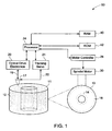
- FIG. 1 illustrates a system 10 for processing information of an optical data storage disk 11.
- the volume of the optical data storage disk 11 includes multiple layers 12.
- the optical data storage disk 11 further includes multiple layers having microholographic symbols arranged in multiple data tracks spiraling around the centre of the optical data storage disk 11.
- optical data storage disk 11 includes a plastic substrate having multiple volumes arranged along the multiple data tracks in multiple vertically stacked, laterally extending layers; and multiple micro-holograms each contained in a corresponding one of the volumes. The presence or absence of a micro-hologram in each of the volumes is indicative of a corresponding portion of data stored.
- the multiple data tracks are located in grooves formed between wobbles.
- one of the layer 13 of the optical data storage disk 11 includes an inner groove 14 with wobbling.
- the layer 13 also depicts an outer groove 16 with the similar wobbling.
- the system 10 includes one pick-up head device 17 for reading and recording information from the optical data storage disk 11.
- the system 10 may include multiple pick-up head devices 17 with optical lenses for processing information at a higher rate.
- the system 10 includes a series of optical elements (not shown) for projecting a read beam 18 onto the optical data storage disk 11. A reflected beam is picked up from the optical data storage disk 11 by the optical elements.
- the pick up head device 17 may comprise any number of different elements designed to generate excitation beams, focus the beams on the optical data storage disk 11, and detect the reflection beam coming back from the optical data storage disk 11.
- the pick up head devices 17 are controlled through a coupling 19 to an optical drive electronics package 20.
- the optical drive electronics package 20 may include such units as power supplies for one or more laser systems, detection electronics to detect an electronic signal from the detector, analog-to-digital converters to convert the detected signal into a digital signal, and other units such as a bit predictor to predict when the detector signal is actually registering a bit value stored on the optical data storage disk 11.
- the location of the pick up head device 17 over the optical data storage disk 11 is controlled by a focus and tracking servo 21 which has a mechanical actuator 22 configured to move the pick up head device 17 in axial and radial directions in relation to the optical data storage disk 11.
- the optical drive electronics package 20 and the tracking servo 21 are controlled by a processor 24.
- the processor 24 is responsive to the data detected by the pick-up head 17 and is capable of sending a location signal and coordinating the movement of the one or more pick-up heads 17.
- the processor 24 may be capable of determining the position of the pick up head device 17, based on sampling information that may be received by the pick up head device 17 and fed back to the processor 24.
- processor for performing the processing tasks.
- processor is intended to denote any machine capable of performing the calculations, or computations, necessary to perform the tasks.
- processor is intended to denote any machine that is capable of accepting a structured input and of processing the input in accordance with prescribed rules to produce an output.
- the processor may be equipped with a combination of hardware and software for performing the tasks, as will be understood by those skilled in the art.
- the position of the pick up head device 17 may be determined to enhance and/or amplify the reflection or to reduce interferences of the reflection.
- the tracking servo 21 or the optical drive electronics 20 may be capable of determining the position of the pick up head device 17 based on sampling information received by the pick up head device 17.
- the processor 24 also controls a motor controller 26, which provides the power 28 to a spindle motor 30.
- the spindle motor 30 is coupled to a spindle 32 that controls the rotational speed of the optical data storage disk 11. As the pick up head devices 17 are moved from the outside edge of the optical data storage disk 11 closer to the spindle 32, the processor 24 may increase the rotational speed of the optical data storage disk 11.
- the movement of pick up head device 17 is proportional to a voltage applied to the mechanical actuator 22.
- the system 10 includes a memory for storing a look-up table having sets of voltage data corresponding to various positions in the optical data storage disk 11.
- the memory is also capable of storing the information read from the optical data storage disk 11.
- the memory is a mass storage random access memory (RAM 40) for storing the multiple data arranged in the look-up table and further provides for storing a reference voltage for allowing the processor 24 to direct a laser beam to a target position.
- the processor 24 is connected to the RAM 40 and a read only memory or ROM 42.
- the ROM 42 contains the programs that allow the processor 24 to control the tracking servo 21, optical drive electronics 20, and motor controller 26.
- the ROM 42 also contains programs that allow the processor 24 to analyze data from the optical drive electronics 20, which has been stored in the RAM 40, among others. It is to be noted that such analysis of the data stored in the RAM 40 may include, for example, demodulation, decoding or other functions necessary to convert the information from the optical data storage disk 11 into a data stream that may be used by other units.
- the system 10 includes a non-limiting example of the look-up table as shown below.
- the look-up table provides for optimal voltage that is required by the actuators for moving the pick-up heads 17, thereby, causing the pick-up heads to focus a laser beam to a target position in a desired layer.
- Track Number Voltage for corresponding track number Layer Number Voltage for corresponding layer number [I] [V] [L] [V] T1 VT1 L1 VL1 T2 VT2 L2 VL2 T3 VT3 L3 VL3 T4 VT4 L4 VL4 T5 VT5 L5 VL5
- the look-up table includes a first set of data (first column) having a sequence of numbers corresponding to the data tracks, a second set of data having voltages (second column) corresponding to multiple data tracks in the layer, a third set of data (third column) having a sequence of numbers corresponding to the multiple layers and a fourth set of data (fourth column) having voltages corresponding to the multiple layers of the storage medium.
- first column having a sequence of numbers corresponding to the data tracks
- second column having voltages
- third column having a sequence of numbers corresponding to the multiple layers
- fourth set of data fourth set of data having voltages corresponding to the multiple layers of the storage medium.
- each of the column may have more number of data than the number as illustrated in the look-up table and depends on the number of layers and data tracks that can be accommodated in an optical data storage medium.
- the look-up table is formed during recording procedure and saved in ROM 42 (read only memory) of the system 10.
- the laser beam is directed to a target layer and a target track based on the look up table.
- the look-up table is formed during recording procedure by the user and saved in a RAM (random access memory) of the system 10 (as shown in FIG. 1 ).
- laser beam is directed to target layer and target track based on the look up table.
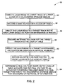
- FIG. 2 illustrates a flow chart of an exemplary method 50 of processing information for read and write the holographic disc.
- the method 50 includes directing a laser beam to a first track of a first layer of a holographic data storage medium. In one embodiment, directing the laser beam to a target track in the first layer includes moving a pick up head horizontally or vertically.
- the method 50 includes recording a base voltage into the look-up table.
- the method 50 includes directing a laser beam to a target (final) track of the first layer of a holographic data storage medium, based on position information in the tracks. The method also includes recording an offset voltage for the target track into the look-up table in step 58.
- the method 50 includes directing a laser beam to a target (final) layer based on position information in vertical wobbles.
- directing the laser beam to a target layer closer to an outer or inner track of a holographic data storage medium includes moving a pick up head horizontally or vertically.
- the method also includes recording an offset voltage for a target layer into the look-up table in step 62.
- the recording of the offset voltage for the target track and the offset voltage for the target layer are both done in the random access memory.
- the method includes determining a final voltage based on the look-up table and includes applying the final voltage to an actuator for moving the laser beam to a final target position in the holographic storage medium for recording or retrieval of information. This movement of the laser beam to a final target position includes focusing an objective lens of the pick-up head to an optimal depth of the target layer.
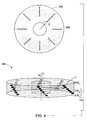
- FIG. 3 illustrates a system 100 for processing information of a multilayer optical holographic data storage disk 102.
- the system 100 includes one optical pick-up head device 103 for reading and recording information from the optical holographic data storage disk 102.
- the system 100 includes multiple pick-up head devices 103 with optical lenses for processing information at a higher rate.
- the volume of the optical data storage disk 102 includes multiple layers 104 shown as 104 1 , 104 2 and 110 N.
- a top view of the holographic data storage disk 102 shows a particular layer 106 having one or more microholographic symbols 108, which microholographic symbols 108 comprises layer, radial and angular location information or address information of a data section, written at an arc of length r ⁇ on a spiral data track, wherein 'r' is the radial distance of the microholographic symbol 108 from the centre of the optical holographic data storage disk 102 and ' ⁇ ' is the angle formed by the arc in the holographic data storage disk 102.
- one or more sets of such holographic symbols 108 can be arranged in different radial locations in one or more layers 104.
- one or more sets of microholographic symbols 108 can be arranged in different angular locations on one or more data layers 104 in the holographic data storage disk 102.
- the holographic symbols 108 are arranged in different radial or angular locations on the data layers 104 such that when the optical pickup head 103 changes focus from one data layer to another data layer or between tracks in same layer during disk rotation, a first address symbol encountered by the optical pickup head device 103, provides for an accurate layer, radial and angular location information for data seeking.
- FIG. 4 shows another embodiment of a multilayer optical holographic data storage disk 200.
- a top view of the holographic data storage disk 200 shows a particular layer 206 having one or more microholographic symbols 208, which microholographic symbols 208 comprises layer, radial and angular location information or address information of a data section, written at an arc of length r ⁇ on a spiral data track, wherein 'r' is the radial distance of the microholographic symbol 208 from the centre of the optical data storage disk 200 and ' ⁇ ' is the angle formed by the arc in the disk 200.
- the microholographic symbol 208 contains location information, for example, data layer number, radial and angular locations in a layer or address information for a data section.
- Corresponding microholographic symbols of the multiple layers 210 are written at the multiple data layers 210 1 , 210 2 , 210 N with an angular offset angle ' ⁇ ' from the adjacent layer for compensating the relative rotational displacement of the holographic data storage disk 200 when an optical pickup head is changing focus from one data layer to another data layer.
- This staircase-like arrangement minimizes the seek time while the optical pick-up head is focusing through different data layers.
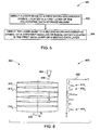
- FIG. 5 is a flow chart of an exemplary method 300 of retrieving information from a holographic data storage medium.
- the method includes directing a laser beam to a first micro-holographic symbol located in a first layer of the holographic data storage medium.
- the micro-holographic symbol contains location information, for example, data layer number, radial and angular locations in a layer or address information for a data section.
- the holographic data storage medium may include the first micro-holographic symbol written at an arc length r ⁇ , wherein 'r' is the radial distance of the microholographic symbol from the centre of the optical data storage disk and ⁇ is the angle formed by the arc to the centre of the disk.
- the method includes directing the laser beam to a second micro-holographic symbol of a different angular or radial offset located in the first layer or a second layer.
- the method 300 provides for reading of microholographic data from one layer to another layer above or below.
- the method 300 further provides for minimizing both the seek time of the pick-up head movement and the processing time for information retrieval.
- FIG. 6 illustrates a system 400 for processing information from an optical data storage disk 402.
- the system 400 includes a pick up head device 404 with optical lenses for focusing a laser beam 406 through the optical data storage disk 402 having 'N' multiple layers 410 1 , 410 2 to 410 N .
- the optical data storage disk 402 spins about an axis 408 with an optimal speed ⁇ in the system 400 during the processing of information.
- Each of the layer 101, 4102 to 410N includes multiple microholographic symbols.
- the pick-up head device 404 is capable of transmitting the laser beam 406 through the multiple layers 410 1 to 410 N and receiving the returned laser beam.
- the system 400 employs a processor for analyzing intensity of the returned laser beam and a suitable display system for displaying results of the analysis in the form of a chart or a plot 420.
- the plot 420 depicts a z-axis signifying depth of the optical data storage disk 402.
- a local maximum in the plot 420 signifies a layer of the optical data storage disk 402.
- the series of 'N' maxima for 'N' multiple layers is represented by 415 1 , 415 2 to 415 N in the plot.
- the system 400 includes an algorithm stored in a memory that enables to focus the laser beam to a target layer for reading and recording of information in the optical data storage disk 402.
- the stored algorithm efficiently allows focusing the laser beam through multiple layers of the optical data storage disk 402 as shown in a flow chart in FIG. 7 .
- FIG. 7 is a flow chart of an exemplary method 500 of focusing a laser beam through multiple layers of an optical data storage medium.
- the method includes focusing the laser beam through the multiple layers of the optical data storage medium.
- the method includes receiving a return beam.
- the method includes analyzing the return beam to provide a result having a series of local maxima for corresponding layers of the optical data storage medium (as shown in FIG. 6 ).
- the method includes determining an initial layer of focus by the laser beam.
- the method includes counting up or down a number of local maximum between the initial layer and a target layer. The local maxima represent optical intensity peaks equal to the number of layers between the initial layer of focus to the new target layer.
- the method includes directing the laser beam to the target layer based on the counting for reading or recording of data in step 512.
- the present method and system enables the processing of information from a holographic data storage medium easily and rapidly using a look-up table stored in a memory.
- the present invention enables the retrieval of information rapidly by minimizing the seek time of the movement of the pick-up heads while jumping from one track to another track in a different layer.
- the present invention also ensures that the pick-up head is accurately focused to read symbol holograms from the correct disc layer in the data storage medium.
Landscapes
- Optical Recording Or Reproduction (AREA)
- Physics & Mathematics (AREA)
- General Physics & Mathematics (AREA)
- Moving Of The Head For Recording And Reproducing By Optical Means (AREA)
Claims (4)
- Une méthode (300) de récupération d'informations à partir d'un support (11) de stockage de données holographiques, comprenant :l'orientation (302-304) d'un faisceau sur une séquence de symboles micro-holographiques agencés dans des emplacements dans plusieurs couches de données, dans lesquels les symboles micro-holographiques comprennent des informations d'emplacement, telles que le numéro de couche, des informations d'emplacement radiales et/ou angulaires dans le support de stockage holographique et/ou des informations d'adresse pour une section de données, caractérisée en ce que la séquence de symboles micro-holographiques agencés dans une pluralité de couches forme une structure en escalier ayant une pluralité de marches dans lesquelles chaque symbole micro-holographique est décalé de façon angulaire par rapport à des symboles correspondants dans des couches adjacentes dans le support de stockage de données holographiques (11).
- La méthode (300) selon la revendication 1, dans laquelle la méthode permet à des signaux d'asservissement de s'adapter selon la distance de décalage, dans laquelle la distance de décalage optimale est variable.
- La méthode (300) selon n'importe quelle revendication précédente, comprenant en outre :la focalisation (502) du faisceau laser à travers la pluralité de couches du support de stockage de données holographiques (11) ;la réception (504) d'un faisceau de retour ;l'analyse (506) du faisceau de retour pour fournir un résultat ayant une série de maximums locaux pour des couches correspondantes du support de stockage de données holographiques (11) ;la détermination (508) d'une couche initiale de foyer par le faisceau laser ;le comptage (510) ascendant ou descendant d'un certain nombre de maximums locaux entre la couche initiale et une couche cible ; etl'orientation (512) du faisceau laser sur la couche cible en se basant sur le comptage pour lire ou enregistrer des données.
- Un système (10) pour traiter des informations, comprenant :un ou plusieurs dispositifs à tête de lecture (17) avec des lentilles optiques pour lire et enregistrer des informations provenant d'un support de stockage de données holographiques (11) ;un ou plusieurs dispositifs d'actionnement pour déplacer le ou les plusieurs dispositifs à tête de lecture (17) ;au moins un d'une unité de commande (26) et d'un processeur (24) sensibles aux données détectées par la tête de lecture, ledit processeur étant susceptible d'envoyer un signal d'emplacement à l'un ou plusieurs dispositifs d'actionnement pour déplacer le ou les plusieurs dispositifs à tête de lecture (17) ;dans lequel le ou les plusieurs dispositifs à tête de lecture (17) dirigent un ou plusieurs faisceaux laser (406) sur une piste cible ou une couche cible ; et une mémoire pour stocker les informations lues à partir du support de stockage de données holographiques (11), dans laquelle la mémoire est une mémoire de stockage de masse à accès direct (RAM 40) pour stocker une pluralité de données agencées dans une table de consultation et pour stocker en outre une tension de référence pour permettre à l'unité de commande de diriger un faisceau laser sur une position cible ; etdans lequel ledit système (10) peut être mis en oeuvre pour récupérer des informations à partir du support de stockage de données holographiques (11) en utilisant la méthode telle que définie dans n'importe quelle revendication précédente.
Applications Claiming Priority (1)
| Application Number | Priority Date | Filing Date | Title |
|---|---|---|---|
| US12/846,085 US8520483B2 (en) | 2010-07-29 | 2010-07-29 | Method and system for processing information from optical disk layers |
Publications (3)
| Publication Number | Publication Date |
|---|---|
| EP2413316A2 EP2413316A2 (fr) | 2012-02-01 |
| EP2413316A3 EP2413316A3 (fr) | 2012-08-29 |
| EP2413316B1 true EP2413316B1 (fr) | 2014-11-26 |
Family
ID=44789303
Family Applications (1)
| Application Number | Title | Priority Date | Filing Date |
|---|---|---|---|
| EP11174099.9A Not-in-force EP2413316B1 (fr) | 2010-07-29 | 2011-07-15 | Procédé et système de traitement d'informations de couches de disque optique |
Country Status (6)
| Country | Link |
|---|---|
| US (1) | US8520483B2 (fr) |
| EP (1) | EP2413316B1 (fr) |
| JP (1) | JP5791990B2 (fr) |
| KR (1) | KR20120011832A (fr) |
| CN (1) | CN102347038B (fr) |
| TW (1) | TWI543154B (fr) |
Families Citing this family (1)
| Publication number | Priority date | Publication date | Assignee | Title |
|---|---|---|---|---|
| DE102019207982A1 (de) | 2019-05-31 | 2020-12-03 | Deere & Company | Sensoranordnung für ein landwirtschaftliches Fahrzeug |
Family Cites Families (38)
| Publication number | Priority date | Publication date | Assignee | Title |
|---|---|---|---|---|
| US5079653A (en) | 1988-07-29 | 1992-01-07 | Seagate Technology, Inc. | Information storage disc transducer position control system using last step damping |
| JPH0359856A (ja) * | 1989-07-28 | 1991-03-14 | Toshiba Corp | データ記録再生装置のヘッド位置決め制御装置 |
| US5278816A (en) | 1989-09-22 | 1994-01-11 | Russell James T | Recording/reproducing system using wavelength/depth selective optical storage medium |
| JP3266627B2 (ja) * | 1991-10-11 | 2002-03-18 | 株式会社日立製作所 | 情報再生装置 |
| US6272095B1 (en) * | 1994-07-22 | 2001-08-07 | California Institute Of Technology | Apparatus and method for storing and/or reading data on an optical disk |
| US5612939A (en) * | 1995-01-27 | 1997-03-18 | Victor Company Of Japan, Ltd. | Optical disk recording and/or reproducing apparatus for performing optimizing operation for servo control with recording and/or reproducing operation |
| WO1997001167A1 (fr) | 1995-06-21 | 1997-01-09 | Massachusetts Institute Of Technology | Appareil et procede permettant d'acceder a des donnees enregistrees sur des supports optiques multichouches |
| WO1998005032A1 (fr) * | 1996-07-31 | 1998-02-05 | Sanyo Electric Co., Ltd. | Dispositif pour disque optique |
| US6322933B1 (en) | 1999-01-12 | 2001-11-27 | Siros Technologies, Inc. | Volumetric track definition for data storage media used to record data by selective alteration of a format hologram |
| US6845071B2 (en) | 2001-03-28 | 2005-01-18 | Matsushita Electric Industrial Co., Ltd. | Optical disc apparatus and recording power determining method thereof |
| JP2003346348A (ja) | 2002-05-29 | 2003-12-05 | Nec Corp | 光ディスクおよびその記録再生方法 |
| JP2004062918A (ja) * | 2002-07-24 | 2004-02-26 | Pioneer Electronic Corp | チルトサーボ装置 |
| US7428205B2 (en) * | 2002-11-27 | 2008-09-23 | General Electric Company | Multi-layer holographic data reading method |
| JP4265304B2 (ja) * | 2003-06-25 | 2009-05-20 | ソニー株式会社 | ホログラム記録装置、ホログラム記録方法、ホログラム再生装置、ホログラム再生方法、およびホログラム記録媒体 |
| TWI260013B (en) * | 2003-12-04 | 2006-08-11 | Mediatek Inc | Optical incidence auto-adjusting system |
| JP2006155831A (ja) * | 2004-11-30 | 2006-06-15 | Fujitsu Ltd | ホログラム記録媒体及びホログラム記録再生装置 |
| JP2006179080A (ja) | 2004-12-21 | 2006-07-06 | Sanyo Electric Co Ltd | 傾斜検出装置、ホログラム装置、媒体の傾斜補正方法、ホログラム媒体の傾斜補正方法 |
| US7283286B2 (en) | 2004-12-27 | 2007-10-16 | Sony Corporation | Hologram recording/reproducing device and optical unit |
| JP2007066404A (ja) * | 2005-08-30 | 2007-03-15 | Fujifilm Corp | 光記録方法、光記録装置、光記録媒体及び光記録再生方法 |
| JP2007102849A (ja) * | 2005-09-30 | 2007-04-19 | Toshiba Samsung Storage Technology Corp | 光ディスク装置および光ディスク装置の制御方法 |
| JP2007101939A (ja) * | 2005-10-05 | 2007-04-19 | Sanyo Electric Co Ltd | ホログラム装置、ホログラム装置の記録方法 |
| JP4523553B2 (ja) * | 2006-01-26 | 2010-08-11 | 株式会社日立エルジーデータストレージ | 光ディスク装置およびフォーカス制御方法 |
| WO2007114240A1 (fr) | 2006-03-31 | 2007-10-11 | Pioneer Corporation | Enregistreur-lecteur de données optiques, lecteur de données optiques, et procédé d'enregistrement-lecture de données optiques |
| JP2008071434A (ja) * | 2006-09-14 | 2008-03-27 | Sony Corp | 光ディスク装置、光ディスク、記録制御方法並びに再生制御方法 |
| JP4784474B2 (ja) | 2006-10-13 | 2011-10-05 | ソニー株式会社 | 光ディスク装置及び焦点位置制御方法 |
| EP1970906A1 (fr) | 2007-03-15 | 2008-09-17 | Deutsche Thomson OHG | Procédé et support de stockage pour calibrer un système de stockage holographique |
| TW200849232A (en) | 2007-03-23 | 2008-12-16 | Koninkl Philips Electronics Nv | Method for tracking the information track of an optical disc |
| JP2008251134A (ja) | 2007-03-30 | 2008-10-16 | Sony Corp | 光ディスク装置、情報記録方法及び情報再生方法 |
| JP4389184B2 (ja) | 2007-06-29 | 2009-12-24 | ソニー株式会社 | 光情報記録再生装置 |
| JP5075556B2 (ja) | 2007-09-28 | 2012-11-21 | 株式会社日立製作所 | 光情報記録/再生装置及びディスク判別方法 |
| KR101439846B1 (ko) | 2007-12-12 | 2014-09-12 | 삼성전자주식회사 | 홀로그래픽 정보 저장매체와, 이를 이용한 홀로그래픽 정보기록/재생 장치 및 방법 |
| KR20090076103A (ko) * | 2008-01-07 | 2009-07-13 | 삼성전자주식회사 | 홀로그래픽 정보 기록/재생 시스템의 서보 제어 장치 및방법 |
| KR100987779B1 (ko) | 2008-06-30 | 2010-10-13 | 경원훼라이트공업 주식회사 | 홀로그래피 정보 저장 장치용 액츄에이터 |
| JP2010040064A (ja) | 2008-07-31 | 2010-02-18 | Sony Corp | 光ディスク装置及び信号生成方法 |
| KR100982520B1 (ko) | 2008-09-10 | 2010-09-16 | 삼성전자주식회사 | 광디스크, 광디스크에 대한 기록/재생 방법 및 장치 |
| US20100157774A1 (en) * | 2008-12-23 | 2010-06-24 | General Electric Company | Data storage systems and methods |
| US8182966B2 (en) | 2008-12-23 | 2012-05-22 | General Electric Company | Data storage devices and methods |
| US7990818B2 (en) * | 2008-12-23 | 2011-08-02 | General Electric Company | Cascaded control of a pick-up head for multi-layer optical data storage |
-
2010
- 2010-07-29 US US12/846,085 patent/US8520483B2/en not_active Expired - Fee Related
-
2011
- 2011-07-15 EP EP11174099.9A patent/EP2413316B1/fr not_active Not-in-force
- 2011-07-18 TW TW100125338A patent/TWI543154B/zh not_active IP Right Cessation
- 2011-07-27 JP JP2011163774A patent/JP5791990B2/ja not_active Expired - Fee Related
- 2011-07-29 CN CN201110224473.6A patent/CN102347038B/zh not_active Expired - Fee Related
- 2011-07-29 KR KR1020110075656A patent/KR20120011832A/ko not_active Application Discontinuation
Also Published As
| Publication number | Publication date |
|---|---|
| CN102347038A (zh) | 2012-02-08 |
| KR20120011832A (ko) | 2012-02-08 |
| US8520483B2 (en) | 2013-08-27 |
| US20120026855A1 (en) | 2012-02-02 |
| EP2413316A2 (fr) | 2012-02-01 |
| JP2012033256A (ja) | 2012-02-16 |
| TWI543154B (zh) | 2016-07-21 |
| TW201220306A (en) | 2012-05-16 |
| CN102347038B (zh) | 2016-08-10 |
| EP2413316A3 (fr) | 2012-08-29 |
| JP5791990B2 (ja) | 2015-10-07 |
Similar Documents
| Publication | Publication Date | Title |
|---|---|---|
| KR101014326B1 (ko) | 다층 광정보 매체 및 그 광정보 처리 장치, 프로그램 제품 및 이를 구비한 정보 매체 | |
| EP1607949B1 (fr) | Support d'enregistrement optique | |
| US8125862B2 (en) | System and method for controlling tracking in an optical drive | |
| EP2375412B1 (fr) | Système et procédé pour le transfert de données stockées sur un support de stockage holographique | |
| EP2413316B1 (fr) | Procédé et système de traitement d'informations de couches de disque optique | |
| KR20050057547A (ko) | 결함 영역 관리 | |
| EP2693433A2 (fr) | Support de stockage de données holographiques et procédé associé de celui-ci | |
| JPH1079126A (ja) | 光ディスク装置のアクセス方法 | |
| EP1679715A1 (fr) | Procédé de recherche d'un position cible sur un disque multicouche | |
| JP2010040148A (ja) | 情報記録媒体および情報記録再生装置 | |
| KR100697802B1 (ko) | 광디스크 기록 방법 및 광디스크 기록 장치 | |
| WO2005106860A1 (fr) | Saut mesure en fonction de la vitesse de transfert d'un moteur | |
| US20070053251A1 (en) | Defect area management | |
| JP6091746B2 (ja) | 精密なサーボのシステム及び方法 | |
| CN101751946A (zh) | 光盘记录方法和光盘装置 | |
| JP3968036B2 (ja) | 光ディスク装置とそのフォーカス制御方法 | |
| JP2007536693A (ja) | ヘッド範囲制御ジャンプ | |
| JPS6159673A (ja) | 光デイスク装置のトラツクアクセス方法および光デイスク | |
| JP4699142B2 (ja) | 検査用光ディスク、および、光ディスクドライブまたは光ピックアップの検査方法 | |
| US20120026271A1 (en) | Optical disc recording device and method for drawing image on optical disc | |
| US20080002545A1 (en) | Optical disc apparatus and optical disc determining method | |
| JP2003196852A (ja) | 光ディスク装置 | |
| JPH07302172A (ja) | ディスクおよびディスク駆動装置 | |
| CN101192424A (zh) | 光盘设备和光盘再现方法 | |
| JPH07296396A (ja) | 光記録再生方法及び光ディスク |
Legal Events
| Date | Code | Title | Description |
|---|---|---|---|
| AK | Designated contracting states |
Kind code of ref document: A2 Designated state(s): AL AT BE BG CH CY CZ DE DK EE ES FI FR GB GR HR HU IE IS IT LI LT LU LV MC MK MT NL NO PL PT RO RS SE SI SK SM TR |
|
| AX | Request for extension of the european patent |
Extension state: BA ME |
|
| PUAI | Public reference made under article 153(3) epc to a published international application that has entered the european phase |
Free format text: ORIGINAL CODE: 0009012 |
|
| PUAL | Search report despatched |
Free format text: ORIGINAL CODE: 0009013 |
|
| AK | Designated contracting states |
Kind code of ref document: A3 Designated state(s): AL AT BE BG CH CY CZ DE DK EE ES FI FR GB GR HR HU IE IS IT LI LT LU LV MC MK MT NL NO PL PT RO RS SE SI SK SM TR |
|
| AX | Request for extension of the european patent |
Extension state: BA ME |
|
| RIC1 | Information provided on ipc code assigned before grant |
Ipc: G11B 7/0065 20060101AFI20120725BHEP |
|
| 17P | Request for examination filed |
Effective date: 20130228 |
|
| GRAP | Despatch of communication of intention to grant a patent |
Free format text: ORIGINAL CODE: EPIDOSNIGR1 |
|
| INTG | Intention to grant announced |
Effective date: 20140725 |
|
| GRAS | Grant fee paid |
Free format text: ORIGINAL CODE: EPIDOSNIGR3 |
|
| GRAA | (expected) grant |
Free format text: ORIGINAL CODE: 0009210 |
|
| AK | Designated contracting states |
Kind code of ref document: B1 Designated state(s): AL AT BE BG CH CY CZ DE DK EE ES FI FR GB GR HR HU IE IS IT LI LT LU LV MC MK MT NL NO PL PT RO RS SE SI SK SM TR |
|
| REG | Reference to a national code |
Ref country code: GB Ref legal event code: FG4D |
|
| REG | Reference to a national code |
Ref country code: CH Ref legal event code: EP |
|
| REG | Reference to a national code |
Ref country code: AT Ref legal event code: REF Ref document number: 698590 Country of ref document: AT Kind code of ref document: T Effective date: 20141215 |
|
| REG | Reference to a national code |
Ref country code: IE Ref legal event code: FG4D |
|
| REG | Reference to a national code |
Ref country code: DE Ref legal event code: R096 Ref document number: 602011011678 Country of ref document: DE Effective date: 20150108 |
|
| REG | Reference to a national code |
Ref country code: NL Ref legal event code: VDEP Effective date: 20141126 |
|
| REG | Reference to a national code |
Ref country code: AT Ref legal event code: MK05 Ref document number: 698590 Country of ref document: AT Kind code of ref document: T Effective date: 20141126 |
|
| REG | Reference to a national code |
Ref country code: LT Ref legal event code: MG4D |
|
| PG25 | Lapsed in a contracting state [announced via postgrant information from national office to epo] |
Ref country code: LT Free format text: LAPSE BECAUSE OF FAILURE TO SUBMIT A TRANSLATION OF THE DESCRIPTION OR TO PAY THE FEE WITHIN THE PRESCRIBED TIME-LIMIT Effective date: 20141126 Ref country code: PT Free format text: LAPSE BECAUSE OF FAILURE TO SUBMIT A TRANSLATION OF THE DESCRIPTION OR TO PAY THE FEE WITHIN THE PRESCRIBED TIME-LIMIT Effective date: 20150326 Ref country code: NO Free format text: LAPSE BECAUSE OF FAILURE TO SUBMIT A TRANSLATION OF THE DESCRIPTION OR TO PAY THE FEE WITHIN THE PRESCRIBED TIME-LIMIT Effective date: 20150226 Ref country code: IS Free format text: LAPSE BECAUSE OF FAILURE TO SUBMIT A TRANSLATION OF THE DESCRIPTION OR TO PAY THE FEE WITHIN THE PRESCRIBED TIME-LIMIT Effective date: 20150326 Ref country code: NL Free format text: LAPSE BECAUSE OF FAILURE TO SUBMIT A TRANSLATION OF THE DESCRIPTION OR TO PAY THE FEE WITHIN THE PRESCRIBED TIME-LIMIT Effective date: 20141126 Ref country code: FI Free format text: LAPSE BECAUSE OF FAILURE TO SUBMIT A TRANSLATION OF THE DESCRIPTION OR TO PAY THE FEE WITHIN THE PRESCRIBED TIME-LIMIT Effective date: 20141126 Ref country code: ES Free format text: LAPSE BECAUSE OF FAILURE TO SUBMIT A TRANSLATION OF THE DESCRIPTION OR TO PAY THE FEE WITHIN THE PRESCRIBED TIME-LIMIT Effective date: 20141126 |
|
| PG25 | Lapsed in a contracting state [announced via postgrant information from national office to epo] |
Ref country code: RS Free format text: LAPSE BECAUSE OF FAILURE TO SUBMIT A TRANSLATION OF THE DESCRIPTION OR TO PAY THE FEE WITHIN THE PRESCRIBED TIME-LIMIT Effective date: 20141126 Ref country code: AT Free format text: LAPSE BECAUSE OF FAILURE TO SUBMIT A TRANSLATION OF THE DESCRIPTION OR TO PAY THE FEE WITHIN THE PRESCRIBED TIME-LIMIT Effective date: 20141126 Ref country code: GR Free format text: LAPSE BECAUSE OF FAILURE TO SUBMIT A TRANSLATION OF THE DESCRIPTION OR TO PAY THE FEE WITHIN THE PRESCRIBED TIME-LIMIT Effective date: 20150227 Ref country code: SE Free format text: LAPSE BECAUSE OF FAILURE TO SUBMIT A TRANSLATION OF THE DESCRIPTION OR TO PAY THE FEE WITHIN THE PRESCRIBED TIME-LIMIT Effective date: 20141126 Ref country code: HR Free format text: LAPSE BECAUSE OF FAILURE TO SUBMIT A TRANSLATION OF THE DESCRIPTION OR TO PAY THE FEE WITHIN THE PRESCRIBED TIME-LIMIT Effective date: 20141126 Ref country code: LV Free format text: LAPSE BECAUSE OF FAILURE TO SUBMIT A TRANSLATION OF THE DESCRIPTION OR TO PAY THE FEE WITHIN THE PRESCRIBED TIME-LIMIT Effective date: 20141126 Ref country code: CY Free format text: LAPSE BECAUSE OF FAILURE TO SUBMIT A TRANSLATION OF THE DESCRIPTION OR TO PAY THE FEE WITHIN THE PRESCRIBED TIME-LIMIT Effective date: 20141126 |
|
| PG25 | Lapsed in a contracting state [announced via postgrant information from national office to epo] |
Ref country code: EE Free format text: LAPSE BECAUSE OF FAILURE TO SUBMIT A TRANSLATION OF THE DESCRIPTION OR TO PAY THE FEE WITHIN THE PRESCRIBED TIME-LIMIT Effective date: 20141126 Ref country code: SK Free format text: LAPSE BECAUSE OF FAILURE TO SUBMIT A TRANSLATION OF THE DESCRIPTION OR TO PAY THE FEE WITHIN THE PRESCRIBED TIME-LIMIT Effective date: 20141126 Ref country code: CZ Free format text: LAPSE BECAUSE OF FAILURE TO SUBMIT A TRANSLATION OF THE DESCRIPTION OR TO PAY THE FEE WITHIN THE PRESCRIBED TIME-LIMIT Effective date: 20141126 Ref country code: RO Free format text: LAPSE BECAUSE OF FAILURE TO SUBMIT A TRANSLATION OF THE DESCRIPTION OR TO PAY THE FEE WITHIN THE PRESCRIBED TIME-LIMIT Effective date: 20141126 Ref country code: DK Free format text: LAPSE BECAUSE OF FAILURE TO SUBMIT A TRANSLATION OF THE DESCRIPTION OR TO PAY THE FEE WITHIN THE PRESCRIBED TIME-LIMIT Effective date: 20141126 |
|
| REG | Reference to a national code |
Ref country code: DE Ref legal event code: R097 Ref document number: 602011011678 Country of ref document: DE |
|
| PG25 | Lapsed in a contracting state [announced via postgrant information from national office to epo] |
Ref country code: PL Free format text: LAPSE BECAUSE OF FAILURE TO SUBMIT A TRANSLATION OF THE DESCRIPTION OR TO PAY THE FEE WITHIN THE PRESCRIBED TIME-LIMIT Effective date: 20141126 |
|
| PLBE | No opposition filed within time limit |
Free format text: ORIGINAL CODE: 0009261 |
|
| STAA | Information on the status of an ep patent application or granted ep patent |
Free format text: STATUS: NO OPPOSITION FILED WITHIN TIME LIMIT |
|
| 26N | No opposition filed |
Effective date: 20150827 |
|
| PG25 | Lapsed in a contracting state [announced via postgrant information from national office to epo] |
Ref country code: IT Free format text: LAPSE BECAUSE OF FAILURE TO SUBMIT A TRANSLATION OF THE DESCRIPTION OR TO PAY THE FEE WITHIN THE PRESCRIBED TIME-LIMIT Effective date: 20141126 |
|
| PG25 | Lapsed in a contracting state [announced via postgrant information from national office to epo] |
Ref country code: SI Free format text: LAPSE BECAUSE OF FAILURE TO SUBMIT A TRANSLATION OF THE DESCRIPTION OR TO PAY THE FEE WITHIN THE PRESCRIBED TIME-LIMIT Effective date: 20141126 Ref country code: MC Free format text: LAPSE BECAUSE OF FAILURE TO SUBMIT A TRANSLATION OF THE DESCRIPTION OR TO PAY THE FEE WITHIN THE PRESCRIBED TIME-LIMIT Effective date: 20141126 |
|
| REG | Reference to a national code |
Ref country code: CH Ref legal event code: PL |
|
| PG25 | Lapsed in a contracting state [announced via postgrant information from national office to epo] |
Ref country code: LU Free format text: LAPSE BECAUSE OF FAILURE TO SUBMIT A TRANSLATION OF THE DESCRIPTION OR TO PAY THE FEE WITHIN THE PRESCRIBED TIME-LIMIT Effective date: 20150715 |
|
| REG | Reference to a national code |
Ref country code: IE Ref legal event code: MM4A |
|
| PG25 | Lapsed in a contracting state [announced via postgrant information from national office to epo] |
Ref country code: LI Free format text: LAPSE BECAUSE OF NON-PAYMENT OF DUE FEES Effective date: 20150731 Ref country code: CH Free format text: LAPSE BECAUSE OF NON-PAYMENT OF DUE FEES Effective date: 20150731 |
|
| REG | Reference to a national code |
Ref country code: FR Ref legal event code: PLFP Year of fee payment: 6 |
|
| PG25 | Lapsed in a contracting state [announced via postgrant information from national office to epo] |
Ref country code: IE Free format text: LAPSE BECAUSE OF NON-PAYMENT OF DUE FEES Effective date: 20150715 |
|
| PGFP | Annual fee paid to national office [announced via postgrant information from national office to epo] |
Ref country code: GB Payment date: 20160727 Year of fee payment: 6 Ref country code: DE Payment date: 20160726 Year of fee payment: 6 |
|
| PGFP | Annual fee paid to national office [announced via postgrant information from national office to epo] |
Ref country code: FR Payment date: 20160726 Year of fee payment: 6 |
|
| PG25 | Lapsed in a contracting state [announced via postgrant information from national office to epo] |
Ref country code: MT Free format text: LAPSE BECAUSE OF FAILURE TO SUBMIT A TRANSLATION OF THE DESCRIPTION OR TO PAY THE FEE WITHIN THE PRESCRIBED TIME-LIMIT Effective date: 20141126 |
|
| PG25 | Lapsed in a contracting state [announced via postgrant information from national office to epo] |
Ref country code: SM Free format text: LAPSE BECAUSE OF FAILURE TO SUBMIT A TRANSLATION OF THE DESCRIPTION OR TO PAY THE FEE WITHIN THE PRESCRIBED TIME-LIMIT Effective date: 20141126 Ref country code: HU Free format text: LAPSE BECAUSE OF FAILURE TO SUBMIT A TRANSLATION OF THE DESCRIPTION OR TO PAY THE FEE WITHIN THE PRESCRIBED TIME-LIMIT; INVALID AB INITIO Effective date: 20110715 Ref country code: BG Free format text: LAPSE BECAUSE OF FAILURE TO SUBMIT A TRANSLATION OF THE DESCRIPTION OR TO PAY THE FEE WITHIN THE PRESCRIBED TIME-LIMIT Effective date: 20141126 |
|
| PG25 | Lapsed in a contracting state [announced via postgrant information from national office to epo] |
Ref country code: TR Free format text: LAPSE BECAUSE OF FAILURE TO SUBMIT A TRANSLATION OF THE DESCRIPTION OR TO PAY THE FEE WITHIN THE PRESCRIBED TIME-LIMIT Effective date: 20141126 |
|
| PG25 | Lapsed in a contracting state [announced via postgrant information from national office to epo] |
Ref country code: BE Free format text: LAPSE BECAUSE OF FAILURE TO SUBMIT A TRANSLATION OF THE DESCRIPTION OR TO PAY THE FEE WITHIN THE PRESCRIBED TIME-LIMIT Effective date: 20141126 |
|
| REG | Reference to a national code |
Ref country code: DE Ref legal event code: R119 Ref document number: 602011011678 Country of ref document: DE |
|
| GBPC | Gb: european patent ceased through non-payment of renewal fee |
Effective date: 20170715 |
|
| REG | Reference to a national code |
Ref country code: FR Ref legal event code: ST Effective date: 20180330 |
|
| PG25 | Lapsed in a contracting state [announced via postgrant information from national office to epo] |
Ref country code: DE Free format text: LAPSE BECAUSE OF NON-PAYMENT OF DUE FEES Effective date: 20180201 Ref country code: GB Free format text: LAPSE BECAUSE OF NON-PAYMENT OF DUE FEES Effective date: 20170715 |
|
| PG25 | Lapsed in a contracting state [announced via postgrant information from national office to epo] |
Ref country code: FR Free format text: LAPSE BECAUSE OF NON-PAYMENT OF DUE FEES Effective date: 20170731 |
|
| PG25 | Lapsed in a contracting state [announced via postgrant information from national office to epo] |
Ref country code: MK Free format text: LAPSE BECAUSE OF FAILURE TO SUBMIT A TRANSLATION OF THE DESCRIPTION OR TO PAY THE FEE WITHIN THE PRESCRIBED TIME-LIMIT Effective date: 20141126 |
|
| PG25 | Lapsed in a contracting state [announced via postgrant information from national office to epo] |
Ref country code: AL Free format text: LAPSE BECAUSE OF FAILURE TO SUBMIT A TRANSLATION OF THE DESCRIPTION OR TO PAY THE FEE WITHIN THE PRESCRIBED TIME-LIMIT Effective date: 20141126 |