EP2412022B1 - Optoelektronisches halbleiterbauteil und anzeigeeinrichtung - Google Patents
Optoelektronisches halbleiterbauteil und anzeigeeinrichtung Download PDFInfo
- Publication number
- EP2412022B1 EP2412022B1 EP10706229.1A EP10706229A EP2412022B1 EP 2412022 B1 EP2412022 B1 EP 2412022B1 EP 10706229 A EP10706229 A EP 10706229A EP 2412022 B1 EP2412022 B1 EP 2412022B1
- Authority
- EP
- European Patent Office
- Prior art keywords
- semiconductor component
- optoelectronic semiconductor
- lens
- lens bodies
- radiation
- Prior art date
- Legal status (The legal status is an assumption and is not a legal conclusion. Google has not performed a legal analysis and makes no representation as to the accuracy of the status listed.)
- Not-in-force
Links
Images


Classifications
-
- H—ELECTRICITY
- H10—SEMICONDUCTOR DEVICES; ELECTRIC SOLID-STATE DEVICES NOT OTHERWISE PROVIDED FOR
- H10H—INORGANIC LIGHT-EMITTING SEMICONDUCTOR DEVICES HAVING POTENTIAL BARRIERS
- H10H20/00—Individual inorganic light-emitting semiconductor devices having potential barriers, e.g. light-emitting diodes [LED]
- H10H20/80—Constructional details
- H10H20/85—Packages
- H10H20/855—Optical field-shaping means, e.g. lenses
-
- H—ELECTRICITY
- H01—ELECTRIC ELEMENTS
- H01L—SEMICONDUCTOR DEVICES NOT COVERED BY CLASS H10
- H01L25/00—Assemblies consisting of a plurality of semiconductor or other solid state devices
- H01L25/03—Assemblies consisting of a plurality of semiconductor or other solid state devices all the devices being of a type provided for in a single subclass of subclasses H10B, H10D, H10F, H10H, H10K or H10N, e.g. assemblies of rectifier diodes
- H01L25/04—Assemblies consisting of a plurality of semiconductor or other solid state devices all the devices being of a type provided for in a single subclass of subclasses H10B, H10D, H10F, H10H, H10K or H10N, e.g. assemblies of rectifier diodes the devices not having separate containers
- H01L25/075—Assemblies consisting of a plurality of semiconductor or other solid state devices all the devices being of a type provided for in a single subclass of subclasses H10B, H10D, H10F, H10H, H10K or H10N, e.g. assemblies of rectifier diodes the devices not having separate containers the devices being of a type provided for in group H10H20/00
- H01L25/0753—Assemblies consisting of a plurality of semiconductor or other solid state devices all the devices being of a type provided for in a single subclass of subclasses H10B, H10D, H10F, H10H, H10K or H10N, e.g. assemblies of rectifier diodes the devices not having separate containers the devices being of a type provided for in group H10H20/00 the devices being arranged next to each other
-
- H—ELECTRICITY
- H01—ELECTRIC ELEMENTS
- H01L—SEMICONDUCTOR DEVICES NOT COVERED BY CLASS H10
- H01L25/00—Assemblies consisting of a plurality of semiconductor or other solid state devices
- H01L25/03—Assemblies consisting of a plurality of semiconductor or other solid state devices all the devices being of a type provided for in a single subclass of subclasses H10B, H10D, H10F, H10H, H10K or H10N, e.g. assemblies of rectifier diodes
- H01L25/10—Assemblies consisting of a plurality of semiconductor or other solid state devices all the devices being of a type provided for in a single subclass of subclasses H10B, H10D, H10F, H10H, H10K or H10N, e.g. assemblies of rectifier diodes the devices having separate containers
- H01L25/13—Assemblies consisting of a plurality of semiconductor or other solid state devices all the devices being of a type provided for in a single subclass of subclasses H10B, H10D, H10F, H10H, H10K or H10N, e.g. assemblies of rectifier diodes the devices having separate containers the devices being of a type provided for in group H10H20/00
-
- H—ELECTRICITY
- H01—ELECTRIC ELEMENTS
- H01L—SEMICONDUCTOR DEVICES NOT COVERED BY CLASS H10
- H01L2924/00—Indexing scheme for arrangements or methods for connecting or disconnecting semiconductor or solid-state bodies as covered by H01L24/00
- H01L2924/0001—Technical content checked by a classifier
- H01L2924/0002—Not covered by any one of groups H01L24/00, H01L24/00 and H01L2224/00
Definitions
- An optoelectronic semiconductor component is specified.
- a display device is provided with such an optoelectronic semiconductor device.
- the publication DE 10 2004 057 499 A1 relates to a device for generating light.
- a projection system with a light-emitting diode can be found in the document US 2007/0206390 A1 ,
- a lens arrangement is in the document US 6,523,976 B1 played.
- An object to be solved is to specify an optoelectronic semiconductor component which has a homogeneous emission characteristic over a large angular range with respect to a color locus. Furthermore, an object to be solved is to specify a display device with such an optoelectronic semiconductor component.
- the optoelectronic semiconductor component according to the invention comprises at least two optoelectronic semiconductor chips.
- the semiconductor chips are configured as light-emitting diodes, in short LEDs, as laser diodes or as superluminescent diodes.
- the optoelectronic semiconductor component preferably comprises exactly three or exactly four optoelectronic semiconductor chips.
- the at least two optoelectronic semiconductor chips are set up to emit electromagnetic radiation during operation in wavelength regions which are different from one another.
- the optoelectronic semiconductor chips may in this case be designed differently, so that radiation having different wavelengths is generated in active layers of the semiconductor chips.
- the optoelectronic semiconductor chips each emit a primary radiation having a same wavelength and that at least one of the semiconductor chips is followed by a conversion means which at least partially converts the radiation emitted by this semiconductor chip into radiation of a different wavelength.
- this includes a carrier with a mounting surface.
- the carrier is designed, for example, with a plastic material and comprises connection devices for electrical contacting of the Semiconductor chips. Furthermore, the carrier constitutes a unit mechanically carrying the semiconductor component.
- the semiconductor chips are mounted on the mounting surface of the carrier.
- the carrier is then a common carrier for all semiconductor chips.
- the latter comprises at least two lens bodies. Refraction of the radiation emitted by the semiconductor chips takes place at at least one boundary surface of the lens body, in particular at an interface remote from the semiconductor chips.
- the lens body are not rotationally symmetrical. In other words, the lens bodies preferably have at most two planes of symmetry with respect to which the lens bodies are mirror-symmetrically shaped.
- the lens bodies are set up to form the radiation in mutually different emission angles along two mutually orthogonal directions parallel to the mounting surface.
- a different beam expansion or beam bundling takes place through the lens bodies along the two mutually orthogonal directions.
- Parallel to the mounting surface this may mean that a plane is spanned by the two mutually orthogonal directions, which is oriented perpendicular to a main radiation direction of the semiconductor device and / or represents a tangent plane to the mounting surface. So parallel to the mounting surface does not necessarily imply that the mounting surface is flat.
- one of the lens bodies is arranged downstream of each of the semiconductor chips in a radiation direction.
- exactly one of the lens bodies is assigned to each of the semiconductor chips.
- the emission direction is in particular that direction in which the power radiated by the semiconductor component indicates a maximum.
- the emission direction is oriented perpendicular to the two mutually orthogonal directions.
- the optoelectronic semiconductor component comprises at least two optoelectronic semiconductor chips which are set up to emit electromagnetic radiation during operation in mutually different wavelength ranges.
- the semiconductor chips are mounted on a mounting surface of a common carrier.
- the optoelectronic semiconductor component contains at least two lens bodies which are not rotationally symmetrical and which are set up to shape the radiation into mutually different emission angles along two mutually orthogonal directions parallel to the mounting surface.
- each of the semiconductor chips is arranged downstream of or assigned to one of the lens bodies in a radiation direction.
- Each of the semiconductor chips which preferably have different colors, is thus subordinated to a separate lens in the emission direction.
- the emission characteristics may be set differently in a horizontal and a vertical direction.
- the semiconductor component can be used in display devices or displays in which different emission angles in the vertical and horizontal directions are desired.
- the optoelectronic semiconductor device can be designed as a so-called RGB unit.
- one of the semiconductor chips in the red spectral range emits at least one of the semiconductor chips in the green spectral range and another semiconductor chip in the blue spectral range.
- Semiconductor chips which emit radiation in a same color preferably represent a color channel.
- each of the semiconductor chips and / or each of the color channels is preferably electronically controllable individually. By way of the controllability of the color channels, therefore, a color location of a total radiation to be emitted by the semiconductor component can be set, in particular temporally variable.
- the color location of the total radiation emitted by the semiconductor component in a far-field optical field varies over an angular range of at least 30 °, depending on a viewing angle, by at most 0.02 units of the CIELUV standard color chart, preferably by at most 0.005 units.
- a large spacing may mean that the spacing corresponds to at least ten times, preferably at least one hundred times, a lateral dimension of the semiconductor component or the lens body.
- the color locus is preferably determined at a distance of at least 300 mm.
- the fact that the color locus changes by at most 0.02 units, preferably at most 0.005 units over the angular range, may mean that all color loci in the angular range are located in a region of the CIELUV standard color chart which is surrounded by a circle with a radius of 0, 02 units is defined.
- a distance in the CIELUV standard color chart between two color loci of the radiation in the angular range is at most 0.04 units.
- the color location of the total radiation emitted by the semiconductor component changes along a first, in particular horizontal direction of the two mutually orthogonal directions within an angular range of 110 ° by less than 0.04 units of the standard color chart, depending on the viewing angle, in particular by less than 0.01 units.
- the color locus of the radiation which emits from the semiconductor component in the emission direction that is to say in particular in a direction perpendicular to the carrier, preferably serves as the reference for the color locus becomes.
- a chromaticity deviation of the radiation over the indicated angular range, with respect to the color locus of the radiation along the emission direction is less than 0.02 units, in particular less than 0.005 units.
- the color locus changes along a second, in particular vertical direction of the two mutually orthogonal directions within an angular range of 40 ° by less than 0.04 units of the standard color chart, preferably by less than 0.01 units.
- the color change is preferably in each case based on the color location of the radiation along the emission direction.
- a chromaticity deviation of the radiation over the indicated angular range, with respect to the color locus of the radiation along the emission direction is less than 0.02 units, in particular less than 0.005 units.
- an aspect ratio of the lens bodies with respect to the mutually orthogonal directions is between 0.3 and 0.9 inclusive.
- the aspect ratio is in the range of between 0.35 and 0.6 inclusive.
- the aspect ratio here is the quotient of the maximum extent of the lens body along the second direction and the maximum extension of the lens body along the first direction.
- the second direction is in particular that of the two mutually orthogonal directions, in which the emission angle is smaller than with respect to the first direction.
- the maximum dimensions of the lens body along the mutually orthogonal directions are at most nine times the maximum dimensions of the semiconductor chip along the respective directions.
- the maximum dimensions of the lens body are at most eight times, in particular at most seven times the associated maximum dimensions of the semiconductor chip. If, for example, the semiconductor chip has a length of 300 ⁇ m along the first direction, then the maximum extent of the lens body along the first direction is at most 2.7 mm, preferably at most 2.4 mm, in particular at most 2.1 mm.
- a height of the lens body in particular in a direction parallel to the emission direction, is between 0.25 and 0.95 times the maximum extension of the lens body along the two mutually orthogonal directions.
- the height is between 0.5 times and 0.8 times the maximum extent of the lens body. If, for example, the maximum extension of the lens body along the first direction is 1 mm, the height of the lens body is preferably between 0.25 mm and 0.95 mm, in particular between 0.5 mm and 0.8 mm.
- adjacent lens bodies are optically isolated from one another with respect to the radiation emitted by the semiconductor chips.
- not significant means that less than 5%, in particular less than 1% of the radiation power of one of the semiconductor chips passes into adjacent lens bodies.
- the optical isolation between adjacent lens bodies may be realized by a coating on a potting body and / or at least one of the lens bodies.
- the optical isolation can be realized by a beam trap which is mounted on the carrier or integrated in the potting body and / or in at least one of the lens body.
- a distance between adjacent lens bodies can be at least 75 ⁇ m, in particular at least 100 ⁇ m.
- the distance between the adjacent lens bodies is preferably at least 5%, preferably at least 10%, of the height of the lens body, in particular along the emission direction.
- the distance is at least 4%, in particular at least 8% of a maximum extension of the lens body along one of the two mutually orthogonal directions.
- a light collection angle of the lens bodies with respect to the radiation emitted by the associated semiconductor chip along the first direction is at least 145 °, preferably at least 160 °, and at least 130 ° along the vertical direction at least 145 °.
- Such light collection angles make it possible for at least 80%, preferably at least 90% of the radiation power emitted by the semiconductor chip to reach the assigned lens body.
- the lens bodies are each formed differently.
- the optoelectronic semiconductor component does not comprise two lens bodies that have the same geometry within the manufacturing tolerances.
- At least two of the lens bodies of the optoelectronic semiconductor component can have at most one, in particular exactly one, plane of symmetry.
- the plane of symmetry here is preferably a mirror symmetry plane.
- the lens bodies can be arranged in a triangular or quadrangular arrangement in plan view of the mounting surface of the carrier.
- the lens bodies preferably lie in an arrangement corresponding to an equilateral triangle or in a square arrangement.
- the lens body and preferably then the semiconductor components are arranged at the vertices of such a triangle or quadrangle.
- a further semiconductor chip as well as the associated lens body can be arranged centrally, ie in particular in the centroid of the triangle or quadrangle spanned by the other semiconductor chips.
- a potting body is located between the lens bodies and the semiconductor chips. Furthermore, the lens bodies are preferably in at least indirect contact with the potting body and are arranged downstream of the potting body in the emission direction. In particular, the potting body completely surrounds the semiconductor chips, with the exception of sides of the semiconductor chips facing the carrier. In other words, the semiconductor chips are then completely enclosed by the carrier and the potting body.
- the lens body can be glued, poured or fused onto the potting body.
- the lens body and the potting so for example, different and independently produced and assembled later.
- all the lens bodies or, if a casting body is present, all the lens bodies and the casting body are made in one piece and consist of the same material.
- the potting body and all lens body is produced by casting, by pressing or by compression molding in the same process step.
- the potting body and the lens body can comprise or consist of a silicone, an epoxide or a silicone-epoxy hybrid material.
- this comprises at least one shield against external radiation.
- External radiation is in this case such a radiation which is not generated by the optoelectronic semiconductor component itself.
- the extraneous radiation is given by sunlight.
- the shield thus prevents, in particular, that directly incident sunlight strikes the semiconductor chips or a conversion agent, for example.
- a surface shape of at least one or all of the lens bodies follows, within a deviation of a z value of at most 10% of a height T of the respective lens body, the following equation: z x .
- y - 0.33866 x 2 - 0.93234 y 2 - 0.54136 x 4 - 1.25032 x 2 y 2 + 1.78606 y 4 + 0.50057 x 6 + 1.27170 x 4 y 2 + 0.06042 x 2 y 4 - 4.44960 y 6 - 0.10344 x 8th + 1.56205 x 6 y 2 + 6.38833 x 4 y 4 + 2.05268 x 2 y 6 - 18.7818 y 8th - 0.158501 x 10 - 2.955774 x 8th y 2 - 10.73336 x 6 y 4 - 26.66134 x 4 y 6 - 2.344646 x 2 y 8th + 0.127770 y 10 ,
- the surface shape that is to say a boundary surface of the lens body facing away from the carrier, can be approximately described by the given equation.
- this may mean that actual z 'values of the surface shape of the lens body, for a given x and y, lie within an interval of z - 0.1 T to z + 0.1 T, preferably within an interval of z - 0.1. 0.05T to z + 0.05T, with the interval limits included, respectively.
- the actual z 'values therefore deviate from the z values from the equation given by a maximum of 10% of the height T of the lens body, preferably by at most 5% of the height T, from.
- the height T is the maximum height of the lens body.
- a distance between two adjacent lens bodies amounts to at least 10% or at least 156% of a maximum extent of one of the adjacent lens bodies in the same direction.
- the display device comprises an optoelectronic semiconductor component according to the invention.
- this comprises a plurality of pixels.
- the display device represents, for example, a display.
- each of the picture elements is formed by an optoelectronic semiconductor component according to one of the preceding embodiments.
- a distance between adjacent pixels between 4 mm and 75 mm inclusive, preferably between including 8 mm and 50 mm, in particular between 12 mm and 23 mm inclusive.
- the pixels may be arranged in a matrix-like manner in rows and columns. Furthermore, each of the pixels can be controlled individually.
- the display device may be free of a mask.
- a mask is, in particular, a device which is set up to implement time-dependent color filtering of the radiation generated in the pixels.
- the display device is free of a liquid crystal mask, in short LCD mask.
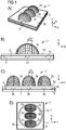
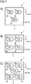
- the semiconductor device 1 comprises a carrier 4 with a mounting surface 40. On the mounting surface 40, three semiconductor chips 2a-c are applied. An electrical contacting of the semiconductor chips 2a-c via in FIG. 1 not shown electrical connection means of the carrier 4.
- Each of the semiconductor chips 2a-c emitted in a different spectral range. For example, the semiconductor chip 2a emits red light, the semiconductor chip 2b emits green light, and the semiconductor chip 2c emits blue light.
- the semiconductor chips 2a-c are separately electrically controllable, so that a color locus of the radiation generated by the semiconductor device 1 is adjustable.
- the potting body 5 represents a kind of pedestal for the lens body 3a-c.
- the recess 7 of the carrier 4 may be provided with at least one reflective, absorbing or colored layer. About this layer on the recess 7 or on the entire support 4 or only on the mounting surface 40 is an appearance and / or optical properties of the semiconductor device 1 are selectively adjustable.
- the lens body 3a-c and the potting body 5 are made in one piece and consist of the same material, for example a silicone, an epoxy or a silicone-epoxy hybrid material.
- Each of the semiconductor chips 2a-c is precisely assigned to one of the lens bodies 3a-c.
- the lens bodies 3a-c have different dimensions and curvatures along a horizontal direction H and along a vertical direction V.
- a tangent plane to the mounting surface 40 is spanned, which is preferably oriented perpendicular to a radiation direction z.
- the emission direction z is, in particular, a main emission direction of the semiconductor component 1 into which a maximum radiation power is emitted.
- the lens body 3a-c are not rotationally symmetrical in particular with respect to the emission direction z.
- An emission characteristic along the horizontal direction H is thereby set differently than a radiation characteristic along the vertical direction V.
- y - 0.33866 x 2 - 0.93234 y 2 - 0.54136 x 4 - 1.25032 x 2 y 2 + 1.78606 y 4 + 0.50057 x 6 + 1.27170 x 4 y 2 + 0.06042 x 2 y 4 - 4.44960 y 6 - 0.10344 x 8th + 1.56205 x 6 y 2 + 6.38833 x 4 y 4 + 2.05268 x 2 y 6 - 18.7818 y 8th - 0.158501 x 10 - 2.955774 x 8th y 2 - 10.73336 x 6 y 4 - 26.66134 x 4 y 6 - 2.344646 x 2 y 8th + 0.127770 y 10 , x, y and z are unitless numbers.
- An x-axis is oriented parallel to the horizontal direction H and a y-axis parallel to the vertical direction V.
- the x and y axes, relative to the respective lens body, intersect in the xy plane, in particular at the point where z is maximal for the respective lens body 3a-c.
- FIG. 2A is in the form of profile lines an intensity distribution of an approximately of the optoelectronic semiconductor device 1 according to FIG. 1 emitted total radiation as a function of an emission angle ⁇ H along the horizontal direction H and an emission angle ⁇ V along the vertical direction V illustrated.
- This radiation power along the emission direction z is normalized to one.
- the total radiation is relative to the vertical Direction V and the horizontal direction H emitted differently.
- an angle-dependent radiation power of at least 6% of the radiation power along the emission direction z is emitted in an angular range of approximately -40 ° to + 40 °, ie over an angular range of approximately 80 °.
- this takes place for angles between approximately -80 ° and + 80 °, ie over a total angular range of approximately 160 °.
- FIG. 2B a corresponding representation is shown with respect to the color location of the total radiation emitted by the semiconductor device 1 in the far-field optical field.
- Far field means here that the distance in which the color locus is determined as a function of the angle is significantly greater than the lateral dimensions of the lens body 2a-c.
- the maximum deviation from the color location of the radiation emitted at the different angles, with respect to the radiation along the emission direction or the main emission direction, is at most 0.020 units in the CIELUV standard color chart.
- the color locus is approximately constant in an angular range of approximately -40 ° to approximately + 40 °, ie over an angular range of approximately 80 °.
- this homogeneity is realized over almost the entire half-plane, ie from approximately -85 ° to approximately + 85 °.
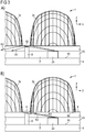
- a beam trap 8 is attached in the embodiment of the semiconductor device 1 according to FIG. 3 is between the adjacent lens bodies 3b, 3c .
- the jet trap 8 consists for example of a radiation-absorbing, opaque material.
- the jet trap 8 may be a part of the carrier 4 or may be incorporated into the encapsulation 5 as a separate component. Unlike in FIG. 3A illustrated, the jet trap 8 may optionally extend to the top 50 of the potting body 5.
- Beam paths R1, R2 of the radiation generated by the semiconductor chip 2b are symbolized by arrow lines.
- a total reflection can take place and the radiation generated by the semiconductor chip 2b, thereby reach the adjacent lens body 3c.
- FIG. 3B is at the top 50 of the potting body 5 in areas that are not covered by the lens bodies 3b, 3c, a coating 9 is attached.
- the coating 9 preferably acts absorbing with respect to the radiation generated by the semiconductor chip 2b. If the coating 9 is applied to the upper side 50, then optionally the jet trap 8 can be omitted.
- a first coating facing the semiconductor chip 2b is designed to be absorbent, and a second coating on the top 50 facing away from the semiconductor chip 2b can be designed in color, white or black.
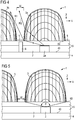
- the adjacent lens body 3 a distance w to each other, which is for example at least 100 microns.
- the distance w is preferably selected to be so large that no radiation generated by the semiconductor chip 2 a that reaches the associated lens body 3 a strikes the adjacent lens body 3 b.
- none or almost none of the radiation generated by the semiconductor chip 2a is influenced by the lens body 3b, for example, by reflection or refraction.
- a Lichteinsammelwinkel along the horizontal direction H is preferably at least 160 °.
- FIG. 6 an embodiment of the optoelectronic component 1 is shown in which the three lens bodies 3a-c are each geometrically shaped differently from each other, compare the schematic sectional view in FIG. 6A and the top view in FIG. 6B ,
- the three lens bodies 3a-c have different heights T1-3 along the emission direction z.
- the lens body 3b has two planes of symmetry, which are defined by the emission direction z and the vertical direction V and by the emission direction z and the horizontal direction H.
- the lens bodies 3a, 3c each have only a single plane of symmetry, which is defined by the vertical direction V and the emission direction z.
- the three semiconductor chips 2a-c each have different heights along the emission direction z. This can also be compensated by the likewise different heights T1-3 of the lens bodies 3a-c, so that each of the radiation emitted by the semiconductor chips 2a-c is emitted in the same or in a comparable manner.
- the distance w between the adjacent lens bodies 3a-c is, for example, at least 10% of the maximum extent L1 along the vertical direction V of the lens body 3b.
- the heights T1-3 of the respective lens bodies 3a-c are respectively preferably between 0.25 times and 0.95 times the associated maximum dimension L2 of the lens body 3b along the horizontal direction H.
- An aspect ratio defined by the quotient of FIG maximum dimensions L1, L2 is preferably between 0.3 and 0.95 inclusive.
- the maximum dimensions L1, L2 of the lens bodies 3a-c are in particular at most six times the associated maximum dimensions C1, C2 of the semiconductor chips 2a-c.
- the maximum extent L2 along the horizontal direction H is, for example, between 1 mm and 2 mm inclusive
- the maximum dimension L1 of the lens body 3 along the vertical direction is, for example, between 0.5 mm and 1.5 mm inclusive.
- the height T2 is preferably less than or equal to 1 mm.
- Lateral dimensions of the entire semiconductor device 1 are, for example, between 1.5 mm ⁇ 1.5 mm and 6 mm ⁇ 6 mm, in particular approximately 3 mm ⁇ 3 mm.
- the lens body 3a-c and the semiconductor chip 2a-c in a triangular arrangement or in a square arrangement, seen in plan view of the carrier 4, arranged.
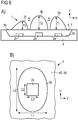
- the semiconductor device 1 has four semiconductor chips 2a-c and four lens bodies 3a-c.
- the semiconductor chips 2b emit, for example, in the green spectral range, the semiconductor chip 2a in the red and the semiconductor chip 2c in the blue spectral range.
- the semiconductor device 1 according to FIG. 7B is therefore a so-called RGGB unit.
- a semiconductor chip 2d and a lens body 3d is arranged in the centroid of the square formed by the semiconductor chip 2a-c and by the lens body 2a-c.
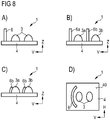
- the optoelectronic semiconductor components 1 each comprise at least one shield 6 against external radiation.
- the foreign radiation is given for example by direct sunlight.
- the semiconductor device 1 comprises exactly one shield 6, which is applied separated from the lens bodies 3 on the carrier 4.
- Each of the lens body 3a, 3b is associated with a shield 6a, 6b.
- the shields 6a, 6b are adapted or molded onto the lens bodies 3a, 3b. It is also possible for the shields 6a, 6b to be encompassed by or integrated in the lens bodies 3a, 3b.
- the shield 6 has an elongated, curved floor plan.
- FIG. 9 an example of a display device 10 is shown.
- the semiconductor devices 1 pixels of the display device 10 are realized.
- a distance D between adjacent pixels and thus between adjacent semiconductor devices 1 is, for example, between 12 mm and 23 mm inclusive.
- the display device 10 is configured to display colored images and / or films.
- semiconductor devices are used, for example, in which multiple chips are arranged downstream of a single mounting lens on a common mounting support.
- generated by the chips in particular different colored radiation from the lens are broken differently, since the chips are, for example, based on an optical axis of the lens at different positions.
- the achievable color homogeneity with respect to a radiation angle is limited. Depending on a viewing angle, this can result in a different color impression.
- conventional display devices may have light-emitting diodes, which have no or only one radially symmetrical lens arranged downstream in the emission direction.
- a radiation is then also typically rotationally symmetric in a cone of light with an opening angle of about 120 °.
- this radiation angle especially in the vertical direction, is too large.
- a radiation intensity in the desired angular range for example 110 ° in the horizontal direction and 40 ° in the vertical direction, is thereby reduced.
Landscapes
- Engineering & Computer Science (AREA)
- Power Engineering (AREA)
- Microelectronics & Electronic Packaging (AREA)
- Physics & Mathematics (AREA)
- Condensed Matter Physics & Semiconductors (AREA)
- General Physics & Mathematics (AREA)
- Computer Hardware Design (AREA)
- Led Device Packages (AREA)
- Devices For Indicating Variable Information By Combining Individual Elements (AREA)
Applications Claiming Priority (2)
| Application Number | Priority Date | Filing Date | Title |
|---|---|---|---|
| DE102009015313.6A DE102009015313B4 (de) | 2009-03-27 | 2009-03-27 | Anzeigeeinrichtung |
| PCT/EP2010/052564 WO2010108761A1 (de) | 2009-03-27 | 2010-03-01 | Optoelektronisches halbleiterbauteil und anzeigeeinrichtung |
Publications (2)
| Publication Number | Publication Date |
|---|---|
| EP2412022A1 EP2412022A1 (de) | 2012-02-01 |
| EP2412022B1 true EP2412022B1 (de) | 2018-11-21 |
Family
ID=42315698
Family Applications (1)
| Application Number | Title | Priority Date | Filing Date |
|---|---|---|---|
| EP10706229.1A Not-in-force EP2412022B1 (de) | 2009-03-27 | 2010-03-01 | Optoelektronisches halbleiterbauteil und anzeigeeinrichtung |
Country Status (8)
| Country | Link |
|---|---|
| US (1) | US8698385B2 (enExample) |
| EP (1) | EP2412022B1 (enExample) |
| JP (1) | JP5744001B2 (enExample) |
| KR (1) | KR101683934B1 (enExample) |
| CN (1) | CN102365739B (enExample) |
| DE (1) | DE102009015313B4 (enExample) |
| TW (1) | TWI419303B (enExample) |
| WO (1) | WO2010108761A1 (enExample) |
Families Citing this family (16)
| Publication number | Priority date | Publication date | Assignee | Title |
|---|---|---|---|---|
| DE102011013052A1 (de) | 2011-03-04 | 2012-09-06 | Osram Opto Semiconductors Gmbh | Verfahren zur Herstellung zumindest eines optoelektronischen Halbleiterbauelements |
| WO2012146316A1 (en) * | 2011-04-27 | 2012-11-01 | Lux Et Libertas B.V. | Led module for a display |
| DE102011107895B4 (de) * | 2011-07-18 | 2020-11-05 | Heraeus Noblelight Gmbh | Optoelektronisches Modul mit Linsensystem |
| DE102011114641B4 (de) * | 2011-09-30 | 2021-08-12 | OSRAM Opto Semiconductors Gesellschaft mit beschränkter Haftung | Optoelektronisches Halbleiterbauelement und Verfahren zur Herstellung eines optoelektronischen Halbleiterbauelements |
| US9136448B2 (en) * | 2012-01-17 | 2015-09-15 | Koninklijke Philips N.V. | Semiconductor light emitting device lamp that emits light at large angles |
| JP6553143B2 (ja) * | 2012-05-09 | 2019-07-31 | ローム株式会社 | 半導体発光装置 |
| CN103791252B (zh) * | 2012-10-30 | 2017-05-03 | 欧司朗股份有限公司 | 发光模块和包括该发光模块的照明装置和灯箱 |
| DE102012110403A1 (de) | 2012-10-30 | 2014-04-30 | Osram Opto Semiconductors Gmbh | Optoelektronisches Bauelement |
| US9470395B2 (en) | 2013-03-15 | 2016-10-18 | Abl Ip Holding Llc | Optic for a light source |
| EP2994290B1 (en) | 2013-05-10 | 2023-10-04 | ABL IP Holding LLC | Silicone optics |
| US9625119B2 (en) * | 2014-07-31 | 2017-04-18 | Excelitas Canada, Inc. | Non-uniform lens array for illumination profile modification |
| DE102014112681A1 (de) * | 2014-09-03 | 2016-03-03 | Osram Opto Semiconductors Gmbh | Optoelektronisches Halbleiterbauteil und Blitzlicht |
| DE102015112042B4 (de) | 2015-07-23 | 2021-07-01 | OSRAM Opto Semiconductors Gesellschaft mit beschränkter Haftung | Optoelektronische Leuchtvorrichtung |
| EP3519886B1 (en) * | 2016-09-27 | 2023-04-26 | Lumileds LLC | Non-rotationally symmetric lens for non-rotationally symmetric light source resulting in rotationally symmetric beam pattern |
| EP3796063B1 (en) * | 2019-09-17 | 2022-10-26 | Axis AB | Lens member for a lens arrangement of a camera device |
| CN115966561A (zh) | 2021-09-30 | 2023-04-14 | 日亚化学工业株式会社 | 发光装置 |
Family Cites Families (19)
| Publication number | Priority date | Publication date | Assignee | Title |
|---|---|---|---|---|
| US5803579A (en) | 1996-06-13 | 1998-09-08 | Gentex Corporation | Illuminator assembly incorporating light emitting diodes |
| JP3399266B2 (ja) | 1996-12-13 | 2003-04-21 | 豊田合成株式会社 | 全色発光型発光ダイオードランプ |
| JP3292133B2 (ja) * | 1997-04-14 | 2002-06-17 | 日亜化学工業株式会社 | Led表示器及びそれを用いた表示装置 |
| US7302181B2 (en) | 2003-02-25 | 2007-11-27 | Avago Technologies Ecbu Ip (Singapore) Pte. Ltd. | Single lens multiple light source device |
| US20050062396A1 (en) | 2003-04-24 | 2005-03-24 | Heston Yang | Multi-hooded pixel |
| US7066623B2 (en) | 2003-12-19 | 2006-06-27 | Soo Ghee Lee | Method and apparatus for producing untainted white light using off-white light emitting diodes |
| GB0409877D0 (en) * | 2004-04-30 | 2004-06-09 | Univ Manchester | Preparation of nanoparticle materials |
| JP3875247B2 (ja) * | 2004-09-27 | 2007-01-31 | 株式会社エンプラス | 発光装置、面光源装置、表示装置及び光束制御部材 |
| US7352011B2 (en) | 2004-11-15 | 2008-04-01 | Philips Lumileds Lighting Company, Llc | Wide emitting lens for LED useful for backlighting |
| JP2007080526A (ja) * | 2005-09-09 | 2007-03-29 | Matsushita Electric Works Ltd | 発光装置 |
| US20070102718A1 (en) | 2005-11-07 | 2007-05-10 | Akira Takekuma | Lens in light emitting device |
| US7832878B2 (en) * | 2006-03-06 | 2010-11-16 | Innovations In Optics, Inc. | Light emitting diode projection system |
| TWI287117B (en) | 2006-05-25 | 2007-09-21 | Ind Tech Res Inst | Light guide lens and light emitting diode package structure having the light guide lens |
| DE102006050880A1 (de) | 2006-06-30 | 2008-04-17 | Osram Opto Semiconductors Gmbh | Optoelektronisches Bauteil und Beleuchtungseinrichtung |
| DE102006046233A1 (de) | 2006-09-26 | 2008-04-03 | Iav Gmbh Ingenieurgesellschaft Auto Und Verkehr | Verfahren und Vorrichtung zum Betrieb einer Verbrennungskraftmaschine |
| DE102006047233A1 (de) * | 2006-10-04 | 2008-04-10 | Osram Opto Semiconductors Gmbh | Optisches Element für eine Leuchtdiode, Leuchtdiode, LED-Anordnung und Verfahren zur Herstellung einer LED-Anordnung |
| JP2008123847A (ja) * | 2006-11-13 | 2008-05-29 | Sony Corp | 面状光源装置及び液晶表示装置組立体 |
| US8540922B2 (en) * | 2007-08-27 | 2013-09-24 | Hewlett-Packard Development Company, L.P. | Laser patterning of a carbon nanotube layer |
| DE102008007723A1 (de) | 2008-02-06 | 2009-08-20 | Osram Gesellschaft mit beschränkter Haftung | Beleuchtungsmodul, Leuchte und Verfahren zur Beleuchtung |
-
2009
- 2009-03-27 DE DE102009015313.6A patent/DE102009015313B4/de not_active Expired - Fee Related
-
2010
- 2010-03-01 CN CN201080015254.0A patent/CN102365739B/zh not_active Expired - Fee Related
- 2010-03-01 KR KR1020117025265A patent/KR101683934B1/ko not_active Expired - Fee Related
- 2010-03-01 EP EP10706229.1A patent/EP2412022B1/de not_active Not-in-force
- 2010-03-01 US US13/202,252 patent/US8698385B2/en active Active
- 2010-03-01 JP JP2012501223A patent/JP5744001B2/ja not_active Expired - Fee Related
- 2010-03-01 WO PCT/EP2010/052564 patent/WO2010108761A1/de not_active Ceased
- 2010-03-19 TW TW099108085A patent/TWI419303B/zh not_active IP Right Cessation
Non-Patent Citations (1)
| Title |
|---|
| None * |
Also Published As
| Publication number | Publication date |
|---|---|
| CN102365739B (zh) | 2014-02-12 |
| TW201104829A (en) | 2011-02-01 |
| WO2010108761A1 (de) | 2010-09-30 |
| JP2012522359A (ja) | 2012-09-20 |
| US8698385B2 (en) | 2014-04-15 |
| KR101683934B1 (ko) | 2016-12-07 |
| CN102365739A (zh) | 2012-02-29 |
| US20120001208A1 (en) | 2012-01-05 |
| JP5744001B2 (ja) | 2015-07-01 |
| KR20110137380A (ko) | 2011-12-22 |
| EP2412022A1 (de) | 2012-02-01 |
| DE102009015313B4 (de) | 2022-02-24 |
| TWI419303B (zh) | 2013-12-11 |
| DE102009015313A1 (de) | 2010-09-30 |
Similar Documents
| Publication | Publication Date | Title |
|---|---|---|
| EP2412022B1 (de) | Optoelektronisches halbleiterbauteil und anzeigeeinrichtung | |
| WO2013139624A1 (de) | Optoelektronischer halbleiterchip und scheinwerfer mit einem solchen halbleiterchip | |
| DE102016119002B4 (de) | Optoelektronisches bauelement und verfahren zum herstellen eines optoelektronischen bauelements | |
| DE102018108022A1 (de) | Vorrichtung zur darstellung eines bildes | |
| DE102011113483B4 (de) | Verfahren zum Herstellen einer Mehrzahl von optoelektronischen Bauelementen und optoelektronisches Bauelement | |
| DE102014112551A1 (de) | Optoelektronischer Halbleiterchip und Verfahren zur Herstellung eines optoelektronischen Halbleiterchips | |
| DE102013212928A1 (de) | Verfahren zum Herstellen eines optoelektronischen Bauelements | |
| DE10314524A1 (de) | Scheinwerfer und Scheinwerferelement | |
| WO2019001767A1 (de) | Optoelektronisches bauelement | |
| WO2013110605A1 (de) | Optikanordnung und verfahren zur optischen abtastung einer objektebene mit einem mehrkanalabbildungssystem | |
| DE102017113745A1 (de) | Halbleiterdisplay, optoelektronisches Halbleiterbauteil und Verfahren zur Herstellung solcher | |
| DE102015118433A1 (de) | Optoelektronisches Bauelement und Verfahren zu seiner Herstellung | |
| DE102016104385A1 (de) | Projektionsoptik, optoelektronischer Halbleiterchip, optoelektronisches Beleuchtungssystem, Kamera, Endgerät | |
| DE112017002405B4 (de) | Optische Anordnung, Verfahren zur Herstellung einer optischen Anordnung und Anzeigegerät | |
| DE102019104986A1 (de) | Optoelektronisches Halbleiterbauteil und Verfahren zur Herstellung eines optoelektronischen Halbleiterbauteils | |
| WO2019072525A1 (de) | Optoelektronisches modul und anzeigeelement | |
| WO2016038009A1 (de) | Optoelektronisches bauteil | |
| WO2020165185A1 (de) | Optoelektronisches bauelement, optoelektronische anordnung und verfahren | |
| WO2025120140A1 (de) | Optoelektronisches bauelement | |
| DE112015004195B4 (de) | Optoelektronisches bauelement | |
| DE102016105988A1 (de) | Konverter zur teilweisen Konversion einer Primärstrahlung und lichtemittierendes Bauelement | |
| DE102017104757B4 (de) | 3D-Anzeigeelement | |
| DE112019003660B4 (de) | Optoelektronisches bauelement und anzeigevorrichtung | |
| EP2122696B1 (de) | Anordnung zur erzeugung von mischlicht und verfahren zur herstellung einer solchen anordnung | |
| DE102018116215A1 (de) | Optoelektronisches Bauelement, Optoelektronische Vorrichtung, Blitzlicht und Leuchte |
Legal Events
| Date | Code | Title | Description |
|---|---|---|---|
| PUAI | Public reference made under article 153(3) epc to a published international application that has entered the european phase |
Free format text: ORIGINAL CODE: 0009012 |
|
| 17P | Request for examination filed |
Effective date: 20110629 |
|
| AK | Designated contracting states |
Kind code of ref document: A1 Designated state(s): AT BE BG CH CY CZ DE DK EE ES FI FR GB GR HR HU IE IS IT LI LT LU LV MC MK MT NL NO PL PT RO SE SI SK SM TR |
|
| DAX | Request for extension of the european patent (deleted) | ||
| GRAP | Despatch of communication of intention to grant a patent |
Free format text: ORIGINAL CODE: EPIDOSNIGR1 |
|
| STAA | Information on the status of an ep patent application or granted ep patent |
Free format text: STATUS: GRANT OF PATENT IS INTENDED |
|
| INTG | Intention to grant announced |
Effective date: 20180801 |
|
| GRAS | Grant fee paid |
Free format text: ORIGINAL CODE: EPIDOSNIGR3 |
|
| GRAA | (expected) grant |
Free format text: ORIGINAL CODE: 0009210 |
|
| STAA | Information on the status of an ep patent application or granted ep patent |
Free format text: STATUS: THE PATENT HAS BEEN GRANTED |
|
| AK | Designated contracting states |
Kind code of ref document: B1 Designated state(s): AT BE BG CH CY CZ DE DK EE ES FI FR GB GR HR HU IE IS IT LI LT LU LV MC MK MT NL NO PL PT RO SE SI SK SM TR |
|
| REG | Reference to a national code |
Ref country code: CH Ref legal event code: EP |
|
| REG | Reference to a national code |
Ref country code: IE Ref legal event code: FG4D Free format text: LANGUAGE OF EP DOCUMENT: GERMAN |
|
| REG | Reference to a national code |
Ref country code: DE Ref legal event code: R096 Ref document number: 502010015579 Country of ref document: DE |
|
| REG | Reference to a national code |
Ref country code: AT Ref legal event code: REF Ref document number: 1068535 Country of ref document: AT Kind code of ref document: T Effective date: 20181215 |
|
| REG | Reference to a national code |
Ref country code: NL Ref legal event code: MP Effective date: 20181121 |
|
| PG25 | Lapsed in a contracting state [announced via postgrant information from national office to epo] |
Ref country code: ES Free format text: LAPSE BECAUSE OF FAILURE TO SUBMIT A TRANSLATION OF THE DESCRIPTION OR TO PAY THE FEE WITHIN THE PRESCRIBED TIME-LIMIT Effective date: 20181121 Ref country code: LV Free format text: LAPSE BECAUSE OF FAILURE TO SUBMIT A TRANSLATION OF THE DESCRIPTION OR TO PAY THE FEE WITHIN THE PRESCRIBED TIME-LIMIT Effective date: 20181121 Ref country code: HR Free format text: LAPSE BECAUSE OF FAILURE TO SUBMIT A TRANSLATION OF THE DESCRIPTION OR TO PAY THE FEE WITHIN THE PRESCRIBED TIME-LIMIT Effective date: 20181121 Ref country code: BG Free format text: LAPSE BECAUSE OF FAILURE TO SUBMIT A TRANSLATION OF THE DESCRIPTION OR TO PAY THE FEE WITHIN THE PRESCRIBED TIME-LIMIT Effective date: 20190221 Ref country code: IS Free format text: LAPSE BECAUSE OF FAILURE TO SUBMIT A TRANSLATION OF THE DESCRIPTION OR TO PAY THE FEE WITHIN THE PRESCRIBED TIME-LIMIT Effective date: 20190321 Ref country code: FI Free format text: LAPSE BECAUSE OF FAILURE TO SUBMIT A TRANSLATION OF THE DESCRIPTION OR TO PAY THE FEE WITHIN THE PRESCRIBED TIME-LIMIT Effective date: 20181121 Ref country code: LT Free format text: LAPSE BECAUSE OF FAILURE TO SUBMIT A TRANSLATION OF THE DESCRIPTION OR TO PAY THE FEE WITHIN THE PRESCRIBED TIME-LIMIT Effective date: 20181121 Ref country code: NO Free format text: LAPSE BECAUSE OF FAILURE TO SUBMIT A TRANSLATION OF THE DESCRIPTION OR TO PAY THE FEE WITHIN THE PRESCRIBED TIME-LIMIT Effective date: 20190221 |
|
| PG25 | Lapsed in a contracting state [announced via postgrant information from national office to epo] |
Ref country code: NL Free format text: LAPSE BECAUSE OF FAILURE TO SUBMIT A TRANSLATION OF THE DESCRIPTION OR TO PAY THE FEE WITHIN THE PRESCRIBED TIME-LIMIT Effective date: 20181121 Ref country code: SE Free format text: LAPSE BECAUSE OF FAILURE TO SUBMIT A TRANSLATION OF THE DESCRIPTION OR TO PAY THE FEE WITHIN THE PRESCRIBED TIME-LIMIT Effective date: 20181121 Ref country code: PT Free format text: LAPSE BECAUSE OF FAILURE TO SUBMIT A TRANSLATION OF THE DESCRIPTION OR TO PAY THE FEE WITHIN THE PRESCRIBED TIME-LIMIT Effective date: 20190321 Ref country code: GR Free format text: LAPSE BECAUSE OF FAILURE TO SUBMIT A TRANSLATION OF THE DESCRIPTION OR TO PAY THE FEE WITHIN THE PRESCRIBED TIME-LIMIT Effective date: 20190222 |
|
| PG25 | Lapsed in a contracting state [announced via postgrant information from national office to epo] |
Ref country code: CZ Free format text: LAPSE BECAUSE OF FAILURE TO SUBMIT A TRANSLATION OF THE DESCRIPTION OR TO PAY THE FEE WITHIN THE PRESCRIBED TIME-LIMIT Effective date: 20181121 Ref country code: DK Free format text: LAPSE BECAUSE OF FAILURE TO SUBMIT A TRANSLATION OF THE DESCRIPTION OR TO PAY THE FEE WITHIN THE PRESCRIBED TIME-LIMIT Effective date: 20181121 Ref country code: IT Free format text: LAPSE BECAUSE OF FAILURE TO SUBMIT A TRANSLATION OF THE DESCRIPTION OR TO PAY THE FEE WITHIN THE PRESCRIBED TIME-LIMIT Effective date: 20181121 Ref country code: PL Free format text: LAPSE BECAUSE OF FAILURE TO SUBMIT A TRANSLATION OF THE DESCRIPTION OR TO PAY THE FEE WITHIN THE PRESCRIBED TIME-LIMIT Effective date: 20181121 |
|
| REG | Reference to a national code |
Ref country code: DE Ref legal event code: R097 Ref document number: 502010015579 Country of ref document: DE |
|
| PG25 | Lapsed in a contracting state [announced via postgrant information from national office to epo] |
Ref country code: SK Free format text: LAPSE BECAUSE OF FAILURE TO SUBMIT A TRANSLATION OF THE DESCRIPTION OR TO PAY THE FEE WITHIN THE PRESCRIBED TIME-LIMIT Effective date: 20181121 Ref country code: RO Free format text: LAPSE BECAUSE OF FAILURE TO SUBMIT A TRANSLATION OF THE DESCRIPTION OR TO PAY THE FEE WITHIN THE PRESCRIBED TIME-LIMIT Effective date: 20181121 Ref country code: EE Free format text: LAPSE BECAUSE OF FAILURE TO SUBMIT A TRANSLATION OF THE DESCRIPTION OR TO PAY THE FEE WITHIN THE PRESCRIBED TIME-LIMIT Effective date: 20181121 Ref country code: SM Free format text: LAPSE BECAUSE OF FAILURE TO SUBMIT A TRANSLATION OF THE DESCRIPTION OR TO PAY THE FEE WITHIN THE PRESCRIBED TIME-LIMIT Effective date: 20181121 |
|
| RAP2 | Party data changed (patent owner data changed or rights of a patent transferred) |
Owner name: OSRAM OPTO SEMICONDUCTORS GMBH |
|
| PLBE | No opposition filed within time limit |
Free format text: ORIGINAL CODE: 0009261 |
|
| STAA | Information on the status of an ep patent application or granted ep patent |
Free format text: STATUS: NO OPPOSITION FILED WITHIN TIME LIMIT |
|
| 26N | No opposition filed |
Effective date: 20190822 |
|
| PG25 | Lapsed in a contracting state [announced via postgrant information from national office to epo] |
Ref country code: SI Free format text: LAPSE BECAUSE OF FAILURE TO SUBMIT A TRANSLATION OF THE DESCRIPTION OR TO PAY THE FEE WITHIN THE PRESCRIBED TIME-LIMIT Effective date: 20181121 Ref country code: MC Free format text: LAPSE BECAUSE OF FAILURE TO SUBMIT A TRANSLATION OF THE DESCRIPTION OR TO PAY THE FEE WITHIN THE PRESCRIBED TIME-LIMIT Effective date: 20181121 |
|
| REG | Reference to a national code |
Ref country code: CH Ref legal event code: PL |
|
| GBPC | Gb: european patent ceased through non-payment of renewal fee |
Effective date: 20190301 |
|
| PG25 | Lapsed in a contracting state [announced via postgrant information from national office to epo] |
Ref country code: LU Free format text: LAPSE BECAUSE OF NON-PAYMENT OF DUE FEES Effective date: 20190301 |
|
| REG | Reference to a national code |
Ref country code: BE Ref legal event code: MM Effective date: 20190331 |
|
| PG25 | Lapsed in a contracting state [announced via postgrant information from national office to epo] |
Ref country code: IE Free format text: LAPSE BECAUSE OF NON-PAYMENT OF DUE FEES Effective date: 20190301 Ref country code: GB Free format text: LAPSE BECAUSE OF NON-PAYMENT OF DUE FEES Effective date: 20190301 Ref country code: LI Free format text: LAPSE BECAUSE OF NON-PAYMENT OF DUE FEES Effective date: 20190331 Ref country code: CH Free format text: LAPSE BECAUSE OF NON-PAYMENT OF DUE FEES Effective date: 20190331 |
|
| PG25 | Lapsed in a contracting state [announced via postgrant information from national office to epo] |
Ref country code: FR Free format text: LAPSE BECAUSE OF NON-PAYMENT OF DUE FEES Effective date: 20190331 Ref country code: BE Free format text: LAPSE BECAUSE OF NON-PAYMENT OF DUE FEES Effective date: 20190331 |
|
| PG25 | Lapsed in a contracting state [announced via postgrant information from national office to epo] |
Ref country code: TR Free format text: LAPSE BECAUSE OF FAILURE TO SUBMIT A TRANSLATION OF THE DESCRIPTION OR TO PAY THE FEE WITHIN THE PRESCRIBED TIME-LIMIT Effective date: 20181121 |
|
| PG25 | Lapsed in a contracting state [announced via postgrant information from national office to epo] |
Ref country code: MT Free format text: LAPSE BECAUSE OF FAILURE TO SUBMIT A TRANSLATION OF THE DESCRIPTION OR TO PAY THE FEE WITHIN THE PRESCRIBED TIME-LIMIT Effective date: 20181121 |
|
| REG | Reference to a national code |
Ref country code: AT Ref legal event code: MM01 Ref document number: 1068535 Country of ref document: AT Kind code of ref document: T Effective date: 20190301 |
|
| PG25 | Lapsed in a contracting state [announced via postgrant information from national office to epo] |
Ref country code: AT Free format text: LAPSE BECAUSE OF NON-PAYMENT OF DUE FEES Effective date: 20190301 |
|
| PG25 | Lapsed in a contracting state [announced via postgrant information from national office to epo] |
Ref country code: CY Free format text: LAPSE BECAUSE OF FAILURE TO SUBMIT A TRANSLATION OF THE DESCRIPTION OR TO PAY THE FEE WITHIN THE PRESCRIBED TIME-LIMIT Effective date: 20181121 |
|
| PGFP | Annual fee paid to national office [announced via postgrant information from national office to epo] |
Ref country code: DE Payment date: 20210319 Year of fee payment: 12 |
|
| PG25 | Lapsed in a contracting state [announced via postgrant information from national office to epo] |
Ref country code: HU Free format text: LAPSE BECAUSE OF FAILURE TO SUBMIT A TRANSLATION OF THE DESCRIPTION OR TO PAY THE FEE WITHIN THE PRESCRIBED TIME-LIMIT; INVALID AB INITIO Effective date: 20100301 |
|
| PG25 | Lapsed in a contracting state [announced via postgrant information from national office to epo] |
Ref country code: MK Free format text: LAPSE BECAUSE OF FAILURE TO SUBMIT A TRANSLATION OF THE DESCRIPTION OR TO PAY THE FEE WITHIN THE PRESCRIBED TIME-LIMIT Effective date: 20181121 |
|
| REG | Reference to a national code |
Ref country code: DE Ref legal event code: R119 Ref document number: 502010015579 Country of ref document: DE |
|
| PG25 | Lapsed in a contracting state [announced via postgrant information from national office to epo] |
Ref country code: DE Free format text: LAPSE BECAUSE OF NON-PAYMENT OF DUE FEES Effective date: 20221001 |
|
| P01 | Opt-out of the competence of the unified patent court (upc) registered |
Effective date: 20230825 |