EP2410544A1 - Staubsauger mit federgelagerten Tritthebeln - Google Patents
Staubsauger mit federgelagerten Tritthebeln Download PDFInfo
- Publication number
- EP2410544A1 EP2410544A1 EP10401113A EP10401113A EP2410544A1 EP 2410544 A1 EP2410544 A1 EP 2410544A1 EP 10401113 A EP10401113 A EP 10401113A EP 10401113 A EP10401113 A EP 10401113A EP 2410544 A1 EP2410544 A1 EP 2410544A1
- Authority
- EP
- European Patent Office
- Prior art keywords
- vacuum cleaner
- levers
- spring element
- stepping
- lever
- Prior art date
- Legal status (The legal status is an assumption and is not a legal conclusion. Google has not performed a legal analysis and makes no representation as to the accuracy of the status listed.)
- Granted
Links
Images
Classifications
-
- A—HUMAN NECESSITIES
- A47—FURNITURE; DOMESTIC ARTICLES OR APPLIANCES; COFFEE MILLS; SPICE MILLS; SUCTION CLEANERS IN GENERAL
- A47L—DOMESTIC WASHING OR CLEANING; SUCTION CLEANERS IN GENERAL
- A47L5/00—Structural features of suction cleaners
- A47L5/12—Structural features of suction cleaners with power-driven air-pumps or air-compressors, e.g. driven by motor vehicle engine vacuum
- A47L5/22—Structural features of suction cleaners with power-driven air-pumps or air-compressors, e.g. driven by motor vehicle engine vacuum with rotary fans
- A47L5/36—Suction cleaners with hose between nozzle and casing; Suction cleaners for fixing on staircases; Suction cleaners for carrying on the back
- A47L5/362—Suction cleaners with hose between nozzle and casing; Suction cleaners for fixing on staircases; Suction cleaners for carrying on the back of the horizontal type, e.g. canister or sledge type
-
- A—HUMAN NECESSITIES
- A47—FURNITURE; DOMESTIC ARTICLES OR APPLIANCES; COFFEE MILLS; SPICE MILLS; SUCTION CLEANERS IN GENERAL
- A47L—DOMESTIC WASHING OR CLEANING; SUCTION CLEANERS IN GENERAL
- A47L9/00—Details or accessories of suction cleaners, e.g. mechanical means for controlling the suction or for effecting pulsating action; Storing devices specially adapted to suction cleaners or parts thereof; Carrying-vehicles specially adapted for suction cleaners
- A47L9/28—Installation of the electric equipment, e.g. adaptation or attachment to the suction cleaner; Controlling suction cleaners by electric means
- A47L9/2836—Installation of the electric equipment, e.g. adaptation or attachment to the suction cleaner; Controlling suction cleaners by electric means characterised by the parts which are controlled
- A47L9/2842—Suction motors or blowers
-
- A—HUMAN NECESSITIES
- A47—FURNITURE; DOMESTIC ARTICLES OR APPLIANCES; COFFEE MILLS; SPICE MILLS; SUCTION CLEANERS IN GENERAL
- A47L—DOMESTIC WASHING OR CLEANING; SUCTION CLEANERS IN GENERAL
- A47L9/00—Details or accessories of suction cleaners, e.g. mechanical means for controlling the suction or for effecting pulsating action; Storing devices specially adapted to suction cleaners or parts thereof; Carrying-vehicles specially adapted for suction cleaners
- A47L9/28—Installation of the electric equipment, e.g. adaptation or attachment to the suction cleaner; Controlling suction cleaners by electric means
- A47L9/2857—User input or output elements for control, e.g. buttons, switches or displays
-
- H—ELECTRICITY
- H01—ELECTRIC ELEMENTS
- H01H—ELECTRIC SWITCHES; RELAYS; SELECTORS; EMERGENCY PROTECTIVE DEVICES
- H01H3/00—Mechanisms for operating contacts
- H01H3/02—Operating parts, i.e. for operating driving mechanism by a mechanical force external to the switch
- H01H3/14—Operating parts, i.e. for operating driving mechanism by a mechanical force external to the switch adapted for operation by a part of the human body other than the hand, e.g. by foot
Definitions
- the invention relates to a vacuum cleaner, in particular a canister vacuum cleaner, with two stepping levers, a first stepping lever preferably for switching on a fan motor and a second stepping lever is preferably used to activate a Jardinierwickelvorraum, and wherein both pedal levers are respectively actuated against the force of a spring element.
- each pedal is supported individually by means of a coil spring relative to the housing.
- a coil spring By the springs, a restoring force is generated, which ensure their return to the starting position after actuation of the pedal. As a result, occur during assembly problems.
- the use of two springs increases the assembly effort, on the other hand, coil springs are difficult to assemble because they can get caught and therefore have to be disconnected before assembly.
- the invention thus raises the problem of facilitating the assembly in a vacuum cleaner of the type mentioned.
- the treadle are at least approximately side by side and the spring element is held in the contact or proximity of the treadle.
- a V-shaped leaf spring can be used. It is expedient depending depending on a free leg end of the leaf spring at a treadle. In order to achieve a good force distribution, it is advantageous if the free leg end is supported on the central region of the stepping lever. In addition, the free leg ends may be bent away from the stepping levers. This avoids entanglement of the leg ends on the step levers.
- the stepping levers are pivotally mounted, it is expedient if their bearing point lies in the contact or proximity area of the stepping levers.
- the treadle be mounted linearly movable.
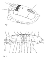
- FIG. 1 shows a vacuum cleaner. This is equipped in the rear area of a control panel 2 with two stepping levers 3 and 4. The right in the direction of travel of the vacuum cleaner lever 3 is used to trigger a not shown, but generally known Jardinaufwickelvorraum. The left lever 4 acts as an ON / OFF switch and starts the engine of a blower, also not shown.
- treadle 3 and 4 The structure of the treadle 3 and 4 is from the FIG. 2 seen.
- the two stepping levers 3 and 4 are next to each other. In their contact area they each have a vertical (in use position) extending wall portion 31 and 41, which is supported on a survey 5.
- both tread levers 3 and 4 are pivotally mounted, ie their outer region 32 or 42 tilts down when actuated and actuates an actuator.
- a Kurzhubtaster 7 When the left treadle a Kurzhubtaster 7 is actuated, which turns on the fan motor.
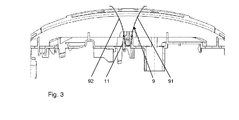
- a jointly acting spring element is used according to the invention for both step levers 3 and 4. It is formed as a V-shaped leaf spring 9 made of spring steel and is stored in the contact region 10 of the treadle 3 and 4 below the survey 5 in a receiving pocket 11.
- the two spring legs 91 and 92 extend upwards and are in the tensioned state with bent ends 93 and 94 on the inner sides of the treadle lever 3 and 4 at.
Landscapes
- Engineering & Computer Science (AREA)
- Mechanical Engineering (AREA)
- Nozzles For Electric Vacuum Cleaners (AREA)
- Electric Suction Cleaners (AREA)
Abstract
Description
- Die Erfindung betrifft einen Staubsauger, insbesondere einen Bodenstaubsauger, mit zwei Tritthebeln, wobei ein erster Tritthebel vorzugsweise zum Einschalten eines Gebläsemotors und ein zweiter Tritthebel vorzugsweise zum Aktivieren einer Kabelaufwickelvorrichtung dient, und wobei beide Tritthebel jeweils gegen die Kraft eines Federelements betätigbar sind.
- Bei Staubsaugern dieser Art wird üblicherweise jeder Tritthebel einzeln mittels einer Schraubenfeder gegenüber dem Gehäuse abgestützt. Durch die Federn wird eine Rückstellkraft erzeugt, welche nach Betätigung der Tritthebel ihre Rückkehr in die Ausgangslage gewährleisten. Hierdurch treten bei der Montage Probleme auf. Einerseits erhöht die Verwendung von zwei Federn den Montageaufwand, andererseits sind Schraubenfedern nur schwer zu montieren, weil sie sich verhaken können und deshalb vor der Montage getrennt werden müssen.
- Der Erfindung stellt sich somit das Problem, bei einem Staubsauger der eingangs genannten Art die Montage zu erleichtern.
- Erfindungsgemäß wird dieses Problem durch einen Staubsauger mit den Merkmalen des Patentanspruchs 1 gelöst. Vorteilhafte Ausgestaltungen und Weiterbildungen der Erfindung ergeben sich aus den nachfolgenden Unteransprüchen.
- Die mit der Erfindung erreichbaren Vorteile ergeben sich daraus, dass ein auf beide Tritthebel wirkendes gemeinsames Federelement zur Anwendung kommt.
- In einer vorteilhaften Ausführungsform liegen die Tritthebel wenigstens annähernd nebeneinander und das Federelement ist im Berührungs- oder Näherungsbereich der Tritthebel gehaltert. Dies vereinfacht den Aufbau des Federelements. Es kann insbesondere eine v-förmig gebogene Blattfeder verwendet werden. Dabei stützt sich zweckmäßig je ein freies Schenkelende der Blattfeder an einem Tritthebel ab. Um eine gute Kraftverteilung zu erreichen, ist es vorteilhaft, wenn sich das freie Schenkelende am mittleren Bereich des Tritthebels abstützt. Außerdem können die freien Schenkelenden von den Tritthebeln weggebogen sein. Hierdurch wird ein Verhaken der Schenkelenden an den Tritthebeln vermieden.
- Wenn die Tritthebel schwenkbar gelagert sind, ist es zweckmäßig, wenn ihr Lagerpunkt im Berührungs- oder Näherungsbereich der Tritthebel liegen. Alternativ können die Tritthebel linear bewegbar gelagert sein.
- Ein Ausführungsbeispiel der Erfindung ist in den Zeichnungen rein schematisch dargestellt und wird nachfolgend näher beschrieben. Es zeigt
- Figur 1
- einen Bodenstaubsauger in perspektivischer Darstellung
- Figur 2
- den Schnitt gemäß
Figur 2 mit eingesetzten Tritthebeln, - Figur 3
- einen Querschnitt durch den in
Figur 1 dargestellten Bodenstaubsauger im Bereich des Federelements bei entfernten Tritthebeln. -
Figur 1 zeigt einen Bodenstaubsauger. Dieser ist im hinteren Bereich eines Bedienfeldes 2 mit zwei Tritthebeln 3 und 4 ausgestattet. Der in Fahrtrichtung des Staubsaugers rechte Hebel 3 dient zum Auslösen einer nicht dargestellten, aber allgemein bekannten Kabelaufwickelvorrichtung. Der linke Hebel 4 fungiert als EIN/AUS-Schalter und startet den Motor eines ebenfalls nicht dargestellten Gebläses. - Der Aufbau der Tritthebel 3 und 4 ist aus der
Figur 2 ersichtlich. Hier ist erkennbar, dass die beiden Tritthebel 3 und 4 nebeneinander liegen. In ihrem Berührungsbereich besitzen sie jeweils ein senkrecht (in Gebrauchslage) verlaufendes Wandteil 31 bzw. 41, welches sich auf einer Erhebung 5 abstützt. Dadurch sind beide Tritthebel 3 und 4 schwenkbar gelagert, d. h. ihr äußerer Bereich 32 bzw. 42 kippt bei Betätigung nach unten und betätigt einen Aktuator. Beim rechten Tritthebel ist dies ein Gestänge 6, welches die Blockierung der Kabelaufwickelvorrichtung löst. Beim linken Tritthebel wird ein Kurzhubtaster 7 betätigt, der den Gebläsemotor einschaltet. Damit nach dem Betätigen die Tritthebel 3 und 4 wieder in ihre Ausgangslage zurückkehren, sind sie im mittleren Bereich 33 bzw. 43 gegenüber dem Staubsaugergehäuse 8 durch ein Federelement abgestützt. In der gezeigten Ausführungsform wird erfindungsgemäß für beide Tritthebel 3 und 4 ein gemeinsam wirkendes Federelement verwendet. Es ist als v-förmig gebogene Blattfeder 9 aus Federstahl ausgebildet und wird im Berührungsbereich 10 der Tritthebel 3 und 4 unterhalb der Erhebung 5 in einer Aufnahmetasche 11 gelagert. Die beiden Federschenkel 91 und 92 erstrecken sich nach oben und liegen im gespannten Zustand mit abgebogenen Enden 93 und 94 an den Innenseiten der Tritthebel 3 und 4 an. Beim Vergleich derFiguren 2 und3 ist erkennbar, dass die Schenkel 91 und 92 bei montierten Tritthebeln 3 und 4 vorgespannt sind. Die Blattfeder 9 kann in der Aufnahmetasche 11 verrastet werden, damit sie bei der Montage oder Demontage nicht verloren geht.
Claims (9)
- Staubsauger (1), insbesondere Bodenstaubsauger, mit zwei Tritthebeln (3, 4), wobei ein erster Tritthebel (3) vorzugsweise zum Einschalten eines Gebläsemotors und ein zweiter Tritthebel (4) vorzugsweise zum Aktivieren einer Kabelaufwickelvorrichtung dient, und wobei beide Tritthebel (3, 4) jeweils gegen die Kraft eines Federelements betätigbar sind, dadurch gekennzeichnet,
dass ein auf beide Tritthebel (3, 4) wirkendes gemeinsames Federelement zur Anwendung kommt. - Staubsauger (1) nach Anspruch 1,
dadurch gekennzeichnet,
dass die Tritthebel (3, 4) wenigstens annähernd nebeneinander liegen und dass das Federelement im Berührungs- oder Näherungsbereich (10) der Tritthebel (3, 4) gehaltert ist. - Staubsauger (1) nach Anspruch 2,
dadurch gekennzeichnet,
dass als Federelement eine v-förmig gebogene Blattfeder (9) verwendet wird. - Staubsauger (1) nach Anspruch 3,
dadurch gekennzeichnet,
dass sich je ein freies Schenkelende (93, 94) der Blattfeder (9) an einem Tritthebel (3, 4) abstützt. - Staubsauger (1) nach Anspruch 5,
dadurch gekennzeichnet,
dass sich die freien Schenkelenden (93, 94) an den mittleren Bereichen (33, 43) der Tritthebel (3, 4) abstützten. - Staubsauger (1) nach Anspruch 4 oder 5,
dadurch gekennzeichnet,
dass die freien Schenkelenden (93, 94) von den Tritthebeln (3, 4) weggebogen sind. - Staubsauger (1) nach einem der vorhergehenden Ansprüche,
dadurch gekennzeichnet,
dass die Tritthebel (3, 4) im hinteren, oberen Gehäusebereich angeordnet sind. - Staubsauger (1) nach einem der vorhergehenden Ansprüche,
dadurch gekennzeichnet,
dass die Tritthebel (3, 4) schwenkbar gelagert sind, wobei ihr Lagerpunkt (5) im Berührungs- oder Näherungsbereich der Tritthebel (3, 4) liegen. - Staubsauger (1) nach einem der vorhergehenden Ansprüche,
dadurch gekennzeichnet,
dass die Tritthebel (3, 4) linear bewegbar gelagert sind.
Priority Applications (1)
| Application Number | Priority Date | Filing Date | Title |
|---|---|---|---|
| EP10401113.5A EP2410544B1 (de) | 2010-07-20 | 2010-07-20 | Staubsauger mit federgelagerten Tritthebeln |
Applications Claiming Priority (1)
| Application Number | Priority Date | Filing Date | Title |
|---|---|---|---|
| EP10401113.5A EP2410544B1 (de) | 2010-07-20 | 2010-07-20 | Staubsauger mit federgelagerten Tritthebeln |
Publications (2)
| Publication Number | Publication Date |
|---|---|
| EP2410544A1 true EP2410544A1 (de) | 2012-01-25 |
| EP2410544B1 EP2410544B1 (de) | 2016-03-16 |
Family
ID=43589407
Family Applications (1)
| Application Number | Title | Priority Date | Filing Date |
|---|---|---|---|
| EP10401113.5A Active EP2410544B1 (de) | 2010-07-20 | 2010-07-20 | Staubsauger mit federgelagerten Tritthebeln |
Country Status (1)
| Country | Link |
|---|---|
| EP (1) | EP2410544B1 (de) |
Citations (2)
| Publication number | Priority date | Publication date | Assignee | Title |
|---|---|---|---|---|
| GB1220789A (en) | 1968-06-11 | 1971-01-27 | Philips Nv | Improvements in or relating to electrical household appliances |
| DE19607148A1 (de) | 1996-02-26 | 1997-08-28 | Siemens Ag | Anordnung einer Schaltwippe an einem Staubsaugergehäuse |
-
2010
- 2010-07-20 EP EP10401113.5A patent/EP2410544B1/de active Active
Patent Citations (2)
| Publication number | Priority date | Publication date | Assignee | Title |
|---|---|---|---|---|
| GB1220789A (en) | 1968-06-11 | 1971-01-27 | Philips Nv | Improvements in or relating to electrical household appliances |
| DE19607148A1 (de) | 1996-02-26 | 1997-08-28 | Siemens Ag | Anordnung einer Schaltwippe an einem Staubsaugergehäuse |
Also Published As
| Publication number | Publication date |
|---|---|
| EP2410544B1 (de) | 2016-03-16 |
Similar Documents
| Publication | Publication Date | Title |
|---|---|---|
| DE68922654T2 (de) | Druckknopf-Schalter. | |
| EP3336292B1 (de) | Verfahren zum betätigen eines türschlosses und türschloss | |
| DE102013221915B4 (de) | Netzbetriebene Handwerkzeugmaschine | |
| DE4030030A1 (de) | Tastenschalter | |
| EP1282907B1 (de) | Elektromechanischer fernschalter | |
| DE102009021595A1 (de) | Steckbares Rohrsystem für einen Staubsauger | |
| DE3220040C2 (de) | Elektromagnetisches Schaltschütz | |
| DE102018219661B4 (de) | Sitzschiene für ein Fahrzeug | |
| EP0515943B1 (de) | Druckschalter | |
| EP2410544B1 (de) | Staubsauger mit federgelagerten Tritthebeln | |
| DE102020129630A1 (de) | Ein verriegelungsmechanismus zum verriegeln einer auslöserbaugruppe eines elektrischen geräts | |
| EP0127853B1 (de) | Klammermagazin für ein manuell oder motorisch angetriebenes Klammergerät | |
| DE19922852C1 (de) | Schalter | |
| DE202021105091U1 (de) | Einbauhandschalter | |
| DE20007090U1 (de) | Klappsitz | |
| EP3007194A1 (de) | Hebelhandschalter | |
| DE102014002870A1 (de) | Steuerschalter mit unverzögerter Schaltung | |
| EP1045412B1 (de) | Mechanismus zur freien Wahl der Tastfunktion | |
| DE102018215717A1 (de) | Bedieneinrichtung | |
| EP2013889B1 (de) | Drehsteller für ein kraftfahrzeug mit jog-shuttle-funktionalität | |
| DE4335993C2 (de) | Betätigungsanordnung an einem elektrischen Gerät | |
| DE102018126384B4 (de) | Schalthebel für ein Fahrzeug, insbesondere für ein Kraftfahrzeug | |
| WO2000039826A1 (de) | Betätigungselement zur herstellung einer schaltverbindung zwischen einem hauptschalter und einem hilfsschalter | |
| DE102017208914A1 (de) | Steuervorrichtung für eine verbesserte Fahrzeugfeststellbremse | |
| DE1201450B (de) | Mikro-Druckknopfschalter mit Sprungschaltglied aus Draht |
Legal Events
| Date | Code | Title | Description |
|---|---|---|---|
| 17P | Request for examination filed |
Effective date: 20110806 |
|
| AK | Designated contracting states |
Kind code of ref document: A1 Designated state(s): AL AT BE BG CH CY CZ DE DK EE ES FI FR GB GR HR HU IE IS IT LI LT LU LV MC MK MT NL NO PL PT RO SE SI SK SM TR |
|
| AX | Request for extension of the european patent |
Extension state: BA ME RS |
|
| PUAI | Public reference made under article 153(3) epc to a published international application that has entered the european phase |
Free format text: ORIGINAL CODE: 0009012 |
|
| GRAP | Despatch of communication of intention to grant a patent |
Free format text: ORIGINAL CODE: EPIDOSNIGR1 |
|
| INTG | Intention to grant announced |
Effective date: 20151013 |
|
| GRAS | Grant fee paid |
Free format text: ORIGINAL CODE: EPIDOSNIGR3 |
|
| GRAA | (expected) grant |
Free format text: ORIGINAL CODE: 0009210 |
|
| AK | Designated contracting states |
Kind code of ref document: B1 Designated state(s): AL AT BE BG CH CY CZ DE DK EE ES FI FR GB GR HR HU IE IS IT LI LT LU LV MC MK MT NL NO PL PT RO SE SI SK SM TR |
|
| REG | Reference to a national code |
Ref country code: GB Ref legal event code: FG4D Free format text: NOT ENGLISH |
|
| REG | Reference to a national code |
Ref country code: GB Ref legal event code: 746 Effective date: 20160308 |
|
| REG | Reference to a national code |
Ref country code: CH Ref legal event code: EP |
|
| REG | Reference to a national code |
Ref country code: IE Ref legal event code: FG4D Free format text: LANGUAGE OF EP DOCUMENT: GERMAN |
|
| REG | Reference to a national code |
Ref country code: DE Ref legal event code: R084 Ref document number: 502010011213 Country of ref document: DE |
|
| REG | Reference to a national code |
Ref country code: AT Ref legal event code: REF Ref document number: 781857 Country of ref document: AT Kind code of ref document: T Effective date: 20160415 |
|
| REG | Reference to a national code |
Ref country code: DE Ref legal event code: R096 Ref document number: 502010011213 Country of ref document: DE |
|
| REG | Reference to a national code |
Ref country code: NL Ref legal event code: MP Effective date: 20160316 |
|
| REG | Reference to a national code |
Ref country code: FR Ref legal event code: PLFP Year of fee payment: 7 |
|
| REG | Reference to a national code |
Ref country code: LT Ref legal event code: MG4D |
|
| PG25 | Lapsed in a contracting state [announced via postgrant information from national office to epo] |
Ref country code: HR Free format text: LAPSE BECAUSE OF FAILURE TO SUBMIT A TRANSLATION OF THE DESCRIPTION OR TO PAY THE FEE WITHIN THE PRESCRIBED TIME-LIMIT Effective date: 20160316 Ref country code: GR Free format text: LAPSE BECAUSE OF FAILURE TO SUBMIT A TRANSLATION OF THE DESCRIPTION OR TO PAY THE FEE WITHIN THE PRESCRIBED TIME-LIMIT Effective date: 20160617 Ref country code: NO Free format text: LAPSE BECAUSE OF FAILURE TO SUBMIT A TRANSLATION OF THE DESCRIPTION OR TO PAY THE FEE WITHIN THE PRESCRIBED TIME-LIMIT Effective date: 20160616 Ref country code: FI Free format text: LAPSE BECAUSE OF FAILURE TO SUBMIT A TRANSLATION OF THE DESCRIPTION OR TO PAY THE FEE WITHIN THE PRESCRIBED TIME-LIMIT Effective date: 20160316 |
|
| PG25 | Lapsed in a contracting state [announced via postgrant information from national office to epo] |
Ref country code: NL Free format text: LAPSE BECAUSE OF FAILURE TO SUBMIT A TRANSLATION OF THE DESCRIPTION OR TO PAY THE FEE WITHIN THE PRESCRIBED TIME-LIMIT Effective date: 20160316 Ref country code: LV Free format text: LAPSE BECAUSE OF FAILURE TO SUBMIT A TRANSLATION OF THE DESCRIPTION OR TO PAY THE FEE WITHIN THE PRESCRIBED TIME-LIMIT Effective date: 20160316 Ref country code: LT Free format text: LAPSE BECAUSE OF FAILURE TO SUBMIT A TRANSLATION OF THE DESCRIPTION OR TO PAY THE FEE WITHIN THE PRESCRIBED TIME-LIMIT Effective date: 20160316 Ref country code: SE Free format text: LAPSE BECAUSE OF FAILURE TO SUBMIT A TRANSLATION OF THE DESCRIPTION OR TO PAY THE FEE WITHIN THE PRESCRIBED TIME-LIMIT Effective date: 20160316 |
|
| PG25 | Lapsed in a contracting state [announced via postgrant information from national office to epo] |
Ref country code: EE Free format text: LAPSE BECAUSE OF FAILURE TO SUBMIT A TRANSLATION OF THE DESCRIPTION OR TO PAY THE FEE WITHIN THE PRESCRIBED TIME-LIMIT Effective date: 20160316 Ref country code: IS Free format text: LAPSE BECAUSE OF FAILURE TO SUBMIT A TRANSLATION OF THE DESCRIPTION OR TO PAY THE FEE WITHIN THE PRESCRIBED TIME-LIMIT Effective date: 20160716 Ref country code: PL Free format text: LAPSE BECAUSE OF FAILURE TO SUBMIT A TRANSLATION OF THE DESCRIPTION OR TO PAY THE FEE WITHIN THE PRESCRIBED TIME-LIMIT Effective date: 20160316 |
|
| PG25 | Lapsed in a contracting state [announced via postgrant information from national office to epo] |
Ref country code: PT Free format text: LAPSE BECAUSE OF FAILURE TO SUBMIT A TRANSLATION OF THE DESCRIPTION OR TO PAY THE FEE WITHIN THE PRESCRIBED TIME-LIMIT Effective date: 20160718 Ref country code: ES Free format text: LAPSE BECAUSE OF FAILURE TO SUBMIT A TRANSLATION OF THE DESCRIPTION OR TO PAY THE FEE WITHIN THE PRESCRIBED TIME-LIMIT Effective date: 20160316 Ref country code: CZ Free format text: LAPSE BECAUSE OF FAILURE TO SUBMIT A TRANSLATION OF THE DESCRIPTION OR TO PAY THE FEE WITHIN THE PRESCRIBED TIME-LIMIT Effective date: 20160316 Ref country code: RO Free format text: LAPSE BECAUSE OF FAILURE TO SUBMIT A TRANSLATION OF THE DESCRIPTION OR TO PAY THE FEE WITHIN THE PRESCRIBED TIME-LIMIT Effective date: 20160316 Ref country code: SK Free format text: LAPSE BECAUSE OF FAILURE TO SUBMIT A TRANSLATION OF THE DESCRIPTION OR TO PAY THE FEE WITHIN THE PRESCRIBED TIME-LIMIT Effective date: 20160316 Ref country code: SM Free format text: LAPSE BECAUSE OF FAILURE TO SUBMIT A TRANSLATION OF THE DESCRIPTION OR TO PAY THE FEE WITHIN THE PRESCRIBED TIME-LIMIT Effective date: 20160316 |
|
| REG | Reference to a national code |
Ref country code: DE Ref legal event code: R097 Ref document number: 502010011213 Country of ref document: DE |
|
| PG25 | Lapsed in a contracting state [announced via postgrant information from national office to epo] |
Ref country code: BE Free format text: LAPSE BECAUSE OF NON-PAYMENT OF DUE FEES Effective date: 20160731 Ref country code: IT Free format text: LAPSE BECAUSE OF FAILURE TO SUBMIT A TRANSLATION OF THE DESCRIPTION OR TO PAY THE FEE WITHIN THE PRESCRIBED TIME-LIMIT Effective date: 20160316 |
|
| PLBE | No opposition filed within time limit |
Free format text: ORIGINAL CODE: 0009261 |
|
| STAA | Information on the status of an ep patent application or granted ep patent |
Free format text: STATUS: NO OPPOSITION FILED WITHIN TIME LIMIT |
|
| PG25 | Lapsed in a contracting state [announced via postgrant information from national office to epo] |
Ref country code: DK Free format text: LAPSE BECAUSE OF FAILURE TO SUBMIT A TRANSLATION OF THE DESCRIPTION OR TO PAY THE FEE WITHIN THE PRESCRIBED TIME-LIMIT Effective date: 20160316 |
|
| 26N | No opposition filed |
Effective date: 20161219 |
|
| PG25 | Lapsed in a contracting state [announced via postgrant information from national office to epo] |
Ref country code: BG Free format text: LAPSE BECAUSE OF FAILURE TO SUBMIT A TRANSLATION OF THE DESCRIPTION OR TO PAY THE FEE WITHIN THE PRESCRIBED TIME-LIMIT Effective date: 20160616 |
|
| REG | Reference to a national code |
Ref country code: CH Ref legal event code: PL |
|
| PG25 | Lapsed in a contracting state [announced via postgrant information from national office to epo] |
Ref country code: MC Free format text: LAPSE BECAUSE OF FAILURE TO SUBMIT A TRANSLATION OF THE DESCRIPTION OR TO PAY THE FEE WITHIN THE PRESCRIBED TIME-LIMIT Effective date: 20160316 |
|
| PG25 | Lapsed in a contracting state [announced via postgrant information from national office to epo] |
Ref country code: LI Free format text: LAPSE BECAUSE OF NON-PAYMENT OF DUE FEES Effective date: 20160731 Ref country code: CH Free format text: LAPSE BECAUSE OF NON-PAYMENT OF DUE FEES Effective date: 20160731 |
|
| REG | Reference to a national code |
Ref country code: IE Ref legal event code: MM4A |
|
| PG25 | Lapsed in a contracting state [announced via postgrant information from national office to epo] |
Ref country code: SI Free format text: LAPSE BECAUSE OF FAILURE TO SUBMIT A TRANSLATION OF THE DESCRIPTION OR TO PAY THE FEE WITHIN THE PRESCRIBED TIME-LIMIT Effective date: 20160316 |
|
| REG | Reference to a national code |
Ref country code: FR Ref legal event code: PLFP Year of fee payment: 8 |
|
| PG25 | Lapsed in a contracting state [announced via postgrant information from national office to epo] |
Ref country code: IE Free format text: LAPSE BECAUSE OF NON-PAYMENT OF DUE FEES Effective date: 20160720 |
|
| PG25 | Lapsed in a contracting state [announced via postgrant information from national office to epo] |
Ref country code: LU Free format text: LAPSE BECAUSE OF NON-PAYMENT OF DUE FEES Effective date: 20160720 |
|
| REG | Reference to a national code |
Ref country code: AT Ref legal event code: MM01 Ref document number: 781857 Country of ref document: AT Kind code of ref document: T Effective date: 20160720 |
|
| PG25 | Lapsed in a contracting state [announced via postgrant information from national office to epo] |
Ref country code: AT Free format text: LAPSE BECAUSE OF NON-PAYMENT OF DUE FEES Effective date: 20160720 |
|
| PG25 | Lapsed in a contracting state [announced via postgrant information from national office to epo] |
Ref country code: HU Free format text: LAPSE BECAUSE OF FAILURE TO SUBMIT A TRANSLATION OF THE DESCRIPTION OR TO PAY THE FEE WITHIN THE PRESCRIBED TIME-LIMIT; INVALID AB INITIO Effective date: 20100720 Ref country code: CY Free format text: LAPSE BECAUSE OF FAILURE TO SUBMIT A TRANSLATION OF THE DESCRIPTION OR TO PAY THE FEE WITHIN THE PRESCRIBED TIME-LIMIT Effective date: 20160316 |
|
| PG25 | Lapsed in a contracting state [announced via postgrant information from national office to epo] |
Ref country code: MT Free format text: LAPSE BECAUSE OF FAILURE TO SUBMIT A TRANSLATION OF THE DESCRIPTION OR TO PAY THE FEE WITHIN THE PRESCRIBED TIME-LIMIT Effective date: 20160316 Ref country code: MK Free format text: LAPSE BECAUSE OF FAILURE TO SUBMIT A TRANSLATION OF THE DESCRIPTION OR TO PAY THE FEE WITHIN THE PRESCRIBED TIME-LIMIT Effective date: 20160316 Ref country code: TR Free format text: LAPSE BECAUSE OF FAILURE TO SUBMIT A TRANSLATION OF THE DESCRIPTION OR TO PAY THE FEE WITHIN THE PRESCRIBED TIME-LIMIT Effective date: 20160316 |
|
| REG | Reference to a national code |
Ref country code: FR Ref legal event code: PLFP Year of fee payment: 9 |
|
| PG25 | Lapsed in a contracting state [announced via postgrant information from national office to epo] |
Ref country code: AL Free format text: LAPSE BECAUSE OF FAILURE TO SUBMIT A TRANSLATION OF THE DESCRIPTION OR TO PAY THE FEE WITHIN THE PRESCRIBED TIME-LIMIT Effective date: 20160316 |
|
| P01 | Opt-out of the competence of the unified patent court (upc) registered |
Effective date: 20230529 |
|
| PGFP | Annual fee paid to national office [announced via postgrant information from national office to epo] |
Ref country code: GB Payment date: 20230725 Year of fee payment: 14 |
|
| PGFP | Annual fee paid to national office [announced via postgrant information from national office to epo] |
Ref country code: FR Payment date: 20230725 Year of fee payment: 14 |
|
| GBPC | Gb: european patent ceased through non-payment of renewal fee |
Effective date: 20240720 |
|
| PG25 | Lapsed in a contracting state [announced via postgrant information from national office to epo] |
Ref country code: FR Free format text: LAPSE BECAUSE OF NON-PAYMENT OF DUE FEES Effective date: 20240731 |
|
| PG25 | Lapsed in a contracting state [announced via postgrant information from national office to epo] |
Ref country code: GB Free format text: LAPSE BECAUSE OF NON-PAYMENT OF DUE FEES Effective date: 20240720 |
|
| PGFP | Annual fee paid to national office [announced via postgrant information from national office to epo] |
Ref country code: DE Payment date: 20250731 Year of fee payment: 16 |