EP2410216B1 - Dichtungsring und vorrichtung zur abdichtung eines heckrohrs - Google Patents
Dichtungsring und vorrichtung zur abdichtung eines heckrohrs Download PDFInfo
- Publication number
- EP2410216B1 EP2410216B1 EP10798945.1A EP10798945A EP2410216B1 EP 2410216 B1 EP2410216 B1 EP 2410216B1 EP 10798945 A EP10798945 A EP 10798945A EP 2410216 B1 EP2410216 B1 EP 2410216B1
- Authority
- EP
- European Patent Office
- Prior art keywords
- lip
- seal ring
- ship propulsion
- propulsion shaft
- arm
- Prior art date
- Legal status (The legal status is an assumption and is not a legal conclusion. Google has not performed a legal analysis and makes no representation as to the accuracy of the status listed.)
- Active
Links
Images


Classifications
-
- B—PERFORMING OPERATIONS; TRANSPORTING
- B63—SHIPS OR OTHER WATERBORNE VESSELS; RELATED EQUIPMENT
- B63H—MARINE PROPULSION OR STEERING
- B63H23/00—Transmitting power from propulsion power plant to propulsive elements
- B63H23/32—Other parts
- B63H23/36—Shaft tubes
-
- F—MECHANICAL ENGINEERING; LIGHTING; HEATING; WEAPONS; BLASTING
- F16—ENGINEERING ELEMENTS AND UNITS; GENERAL MEASURES FOR PRODUCING AND MAINTAINING EFFECTIVE FUNCTIONING OF MACHINES OR INSTALLATIONS; THERMAL INSULATION IN GENERAL
- F16J—PISTONS; CYLINDERS; SEALINGS
- F16J15/00—Sealings
- F16J15/16—Sealings between relatively-moving surfaces
- F16J15/32—Sealings between relatively-moving surfaces with elastic sealings, e.g. O-rings
- F16J15/3204—Sealings between relatively-moving surfaces with elastic sealings, e.g. O-rings with at least one lip
- F16J15/3208—Sealings between relatively-moving surfaces with elastic sealings, e.g. O-rings with at least one lip provided with tension elements, e.g. elastic rings
- F16J15/3212—Sealings between relatively-moving surfaces with elastic sealings, e.g. O-rings with at least one lip provided with tension elements, e.g. elastic rings with metal springs
-
- B—PERFORMING OPERATIONS; TRANSPORTING
- B63—SHIPS OR OTHER WATERBORNE VESSELS; RELATED EQUIPMENT
- B63H—MARINE PROPULSION OR STEERING
- B63H23/00—Transmitting power from propulsion power plant to propulsive elements
- B63H23/32—Other parts
- B63H23/321—Bearings or seals specially adapted for propeller shafts
-
- B—PERFORMING OPERATIONS; TRANSPORTING
- B63—SHIPS OR OTHER WATERBORNE VESSELS; RELATED EQUIPMENT
- B63H—MARINE PROPULSION OR STEERING
- B63H23/00—Transmitting power from propulsion power plant to propulsive elements
- B63H23/32—Other parts
- B63H23/34—Propeller shafts; Paddle-wheel shafts; Attachment of propellers on shafts
-
- F—MECHANICAL ENGINEERING; LIGHTING; HEATING; WEAPONS; BLASTING
- F16—ENGINEERING ELEMENTS AND UNITS; GENERAL MEASURES FOR PRODUCING AND MAINTAINING EFFECTIVE FUNCTIONING OF MACHINES OR INSTALLATIONS; THERMAL INSULATION IN GENERAL
- F16J—PISTONS; CYLINDERS; SEALINGS
- F16J15/00—Sealings
- F16J15/16—Sealings between relatively-moving surfaces
- F16J15/32—Sealings between relatively-moving surfaces with elastic sealings, e.g. O-rings
- F16J15/3204—Sealings between relatively-moving surfaces with elastic sealings, e.g. O-rings with at least one lip
- F16J15/322—Sealings between relatively-moving surfaces with elastic sealings, e.g. O-rings with at least one lip supported in a direction perpendicular to the surfaces
-
- F—MECHANICAL ENGINEERING; LIGHTING; HEATING; WEAPONS; BLASTING
- F16—ENGINEERING ELEMENTS AND UNITS; GENERAL MEASURES FOR PRODUCING AND MAINTAINING EFFECTIVE FUNCTIONING OF MACHINES OR INSTALLATIONS; THERMAL INSULATION IN GENERAL
- F16J—PISTONS; CYLINDERS; SEALINGS
- F16J15/00—Sealings
- F16J15/16—Sealings between relatively-moving surfaces
- F16J15/32—Sealings between relatively-moving surfaces with elastic sealings, e.g. O-rings
- F16J15/3244—Sealings between relatively-moving surfaces with elastic sealings, e.g. O-rings with hydrodynamic pumping action
-
- F—MECHANICAL ENGINEERING; LIGHTING; HEATING; WEAPONS; BLASTING
- F16—ENGINEERING ELEMENTS AND UNITS; GENERAL MEASURES FOR PRODUCING AND MAINTAINING EFFECTIVE FUNCTIONING OF MACHINES OR INSTALLATIONS; THERMAL INSULATION IN GENERAL
- F16J—PISTONS; CYLINDERS; SEALINGS
- F16J15/00—Sealings
- F16J15/16—Sealings between relatively-moving surfaces
- F16J15/40—Sealings between relatively-moving surfaces by means of fluid
Definitions
- invention or “present invention” in this specification means the aspect, the mode or the embodiment disclosed by this specification.
- Patent Reference 1 JP2000-238694
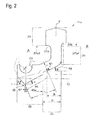
- EP 1 182 133 disclose a stern tube sealing device as shown in Fig. 7 ; the device is provided with lip shaped seal rings 04, 05 and 06 made of elastic material, the lip shaped seal rings keeping contact with a liner 03 fitted to a propulsion shaft (a propeller shaft) 02 penetrating a stern tube 01 so that each seal ring is sandwiched by a housing member 07 and an adjacent housing member 07; the first seal ring 04 on the rearmost side of the ship and the second seal ring 05 next to the first seal ring 04 form a first stern tube annular-space 08, and the second seal ring 05 and the third seal ring 06 form a second stern tube annular-space 09; thus, the stern tube sealing device 010 prevents sea water and foreign matters from entering the inside of the ship, as well as, prevents lubricating oil
- the cross-section profile regarding the seal rings 04, 05 and 06 forms the shape such as shown in Fig. 8 .
- Patent Reference 1 JP2000-238694
- the seal ring used in the stern tube sealing device is configured with:
- the outer periphery seal-part is fitted in the annular groove formed on the inner periphery surface of the casing, so that a tight fit between the outer periphery seal-part and the annular groove is achieved.
- the seal ring is provided with an arm part for supporting the lip seal-part that keeps tight contact with the outer periphery surface of the propeller shaft or the liner.
- the stiffness of this arm part is not adequate, then the contact pressure between the lip seal-part and the outer periphery surface of the propeller shaft or the liner is reduced below an appropriate level; in this case, the sliding surface (the contact surface) of the lip seal-part spreads so that the contact pressure distribution becomes flat; accordingly, an abnormal wear regarding the sliding surface may be caused in an early stage.
- microscopic unevenness (a plurality of projections and depressions) 011 is provided on the sliding surface 012 of the liner 03 fitted at the outer periphery of the propeller shaft 02, so that the water of a lower pressure in a first stern tube annular-space 08 is forcedly delivered to the outboard side of a higher pressure during the propeller rotation; thereby, a seal ring 04 keeps contact with the liner 03 of the propeller shaft 02, at the sliding surface 012, and microscopic unevenness (a plurality of projections and depressions) 011 actively feeds the water outboard during the propeller rotation.
- the disclosure does not cover how to maintain the contact pressure (stress) of the lip seal-part in an appropriate condition, how to evade the leakage through the sliding surface between the lip seal-part and the propeller shaft, how to evade the early stage abnormal-wear regarding the lip seal-part, and how to enhance the sealing performance over the above- described how-to-approaches.
- the present invention aims at providing the seal ring and the stern tube device with the seal ring; whereby, the contact pressure (stress) of the lip seal-part is appropriately established so that the leakage as well as the abnormal-wear in the early stage can be evaded, the durability of the seal ring as well as the sealing performance with the durability can be enhanced, the outer periphery seal-part of the seal ring can be easily fitted in the groove of the casing, and the contact pressure (stress) of the lip seal-part can be stabilized.
- the first invention (a first aspect of the present invention) provides a seal ring provided between a casing member provided on the outboard side of the stern tube and a ship propulsion shaft penetrates the inner space of the casing member so that the seal ring prevents seawater from entering the inboard side, the seal ring including, but not limited to, in view of the cross-section of the seal ring in a plane including the axis of the ship propulsion shaft:
- the seal ring can be easily thrust into the annular groove in the casing; thereby, the seal ring installation is performed from the front side. Accordingly, the easy fitting can be achieved. And, when a ship is put into a dock, the seal ring can be easily replaced by new one, without pulling out the propeller shaft, under the condition that the propeller 3 and the liner 15 are not dismantled.
- a lip tip of the lip part forms a V-shape protruding inward in the radial direction and a spring groove having a semicircular cross-section in which a ringed spring is formed in the lip part; thereby, the center regarding the spring groove is arranged so as to be nearer to the inboard side than the position of the lip tip, by an offset in the propeller shaft axis direction, the offset being within approximately 10% of the orthogonal projection length of the lip back width.
- the angle of the lip tip becomes an obtuse (not-sharp) angle; the contacting surface width around the lip tip becomes greater, and satisfactory contact pressure cannot be achieved because of the excessive contact area.
- sealing performance is deteriorated and early abnormal wear is inclined to occur.
- a part of the seal ring on the front side from the contacting point forms a cantilever beam for which the cantilever deflection formula can be used; the bending deflection V regarding the lip tip is computed by use of the following formula (1).
- an appropriate stiffness of the arm part and the lip part are evaluated with regard to the parameter H3/L4 that appears in the formula (1).
- W the pressure that works on the front face side of the seal ring
- K1 and K2 are constants
- E Young' modulus (regarding the used material such as fluororubber) .
- Another preferable embodiment of the first invention is the seal ring, whereby the stiffness of the arm part and the lip part is established so that the contacting surface width in the neighborhood of the lip tip becomes 2 to 3 mm, when the pressure on the front face side is higher than the pressure on the back face side, by 0.15 MPa, under a condition that the key part is set in the annular groove, the liner is installed, and the lip part keeps tight contact with the outer periphery of the liner that is fitted around or on the outer periphery surface of the ship propulsion shaft.
- the above-described width 2 to 3 mm is based on the results of the confirmation tests in advance.
- the second invention (a second aspect of the present invention) provides a stern tube sealing device provided with a seal ring provided between a casing member provided on the outboard side of the stern tube and a ship propulsion shaft which penetrates the inner space of the casing member so that the seal ring prevents seawater from entering the inboard side, the seal ring including, but not limited to, in view of the cross-section of the seal ring in a plane including the axis of the ship propulsion shaft:
- a stern tube sealing device with the seal ring and the function/performance thereof as per the first invention can be provided.
- Another preferable embodiment of the second invention is the stern tube sealing device, whereby the stiffness of the arm part and the lip part is established so that the contacting surface width in the neighborhood of the lip tip becomes 2 to 3 mm, when the pressure on the front face side is higher than the pressure on the back face side, by 0.15 MPa, under a condition that the key part is set in the annular groove, the liner is installed and the lip part keeps tight contact with the outer periphery of the liner that is fitted around or on the outer periphery surface of the ship propulsion shaft.
- a relief groove is formed near to each middle position in the radial direction on both the sides of the annular groove in which the key part is fitted. Thanks to the relief grooves on both the sides, when the key part is thrust and fitted in the annular groove in the casing, a part of each side wall of the key part enters the relief groove; thus, the relief grooves play role of positioning/fixing function regarding the key part so that the movement of the key part toward the inner side is restrained after the key part is thrust and fitted in the annular groove. In this way, the position of the key part in the casing is locked under the fitted condition; and, stable positioning is achieved.
- the fitting performance regarding the key part of the seal ring fitted in the annular groove can be enhanced; the deformation of the key part while the key part is fitted can be restrained; the deformation of the lip part due to the deformation of the key part is also restrained.
- the contact stress in the lip part changes so that reverse effects on the sealing performance can be evaded.
- the seal ring can be easily thrust and fitted in the annular groove in the casing; and, the replacement regarding the seal rings can be performed on the outer periphery of the liner (or the propeller shaft) without pulling-out the propeller shaft.
- the lip tip of the lip part forms a V-shape protruding inward in the radial direction and a spring groove having a semicircular cross-section in which a ringed spring thrusting the lip part toward the ship propulsion shaft is formed in the lip part; the center regarding the spring groove is arranged so as to be nearer to the inboard side than the position of the lip tip, by an offset in the propeller shaft axis direction, the offset being within approximately 10% of the orthogonal projection length of the lip back width.
- the offset amount becomes approximately 20% of the orthogonal projection length of the lip back width.
- the ringed spring is positioned; and the contact stress in the neighborhood of the lip tip is enhanced; the sealing performance of the lip part can be enhanced.
- the flat (and wide) contact on the lip back side can be hard to appear; thus, the abnormal wear can be prevented from occurring.
- the contact stress in the lip part is maintained so that neither leakage nor abnormal wear can be caused; thus, durability can be enhanced without spoiling sealing performance.
- a stern tube sealing device with the seal ring and the function/effect brought by the seal ring as per the first invention can be provided.
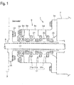
- the stern tube sealing device 1 comprises (i.e. includes, but not limited to):
- the casing 9 comprising a plurality of casing members 9a, 9b, ⁇ , and 9e that are arranged in a stacked condition, and are fastened to the stern tube 7, the casing members 9a, 9b, ⁇ , and 9e forming an integrated part; mutually adjacent two members out of the casing members 9b, 9c, ⁇ , and 9e sandwich the each of the seal rings 11a, 11b and 11c so as to keep hold of the seal rings.
- the tip (lip tip) of the lip seal-part of the first seal ring 11a as well as the second seal ring 11a is directed toward the sea water side so as to prevent sea water from entering the inboard side; incidentally, the first seal ring 11a is arranged at the most stern side, and the second seal ring 11b is arranged next to the first seal ring 11a.
- the tip (lip tip) of the lip seal-part of the third seal ring 11c that is arranged nearest to the inboard side is directed toward the inboard side so as to prevent lubricating oil on the inboard side from leaking toward the outboard side.
- the seal rings 11a, 11b and 11c are made of elastic material such as rubber or elastomer; for example, fluororubber (e.g. Du Pont's product under a brand name "Viton") having superior water-resistance and oil-resistance properties or nitrile-butadiene rubber (NBR) forms the rubber material.
- fluororubber e.g. Du Pont's product under a brand name "Viton”
- NBR nitrile-butadiene rubber
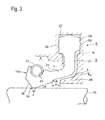
- the seal ring 11a is configured with:
- the height of the key part 29 on the back side is established as a 70-to-80 % length of the height of the key part 29 on the front side; thus, in fitting the key part 29 into the annular groove 27 in the casing 9 (along the Y-arrow direction (of a broken line) in Fig. 3 ), because of the lower height of the key part 29 on the back side, the step part 37b on the back side can be easily fitted into the annular groove 27; and, the installation of the seal ring can be simple and sure, without gripping (regarding the seal ring or the key part) .
- the relation (or difference) between the front side height and the back side height is experimentally established so that easiness in fitting and stableness after installation can be achieved.
- the key part 29 is prevented from failing to be smoothly fitted into the annular groove, from being gripped and deforming, and from causing deformation of the contact surface on the side of the lip part 35. In this way, the possibility that the sealing performance is hindered due to the change of the contact stress (pressure) of the lip part 35 can be evaded.
- the seal ring 11a can be easily thrust into the annular groove 27 in the casing 9; thereby, the seal ring installation is performed from the front side. Accordingly, for instance, when a ship is put into a dock, the seal ring 11a can be replaced by new one, without pulling out the propeller shaft 5, under the condition that the propeller 3 and the liner 15 are dismantled.
- the arm part 33 is formed so that the arm part is extended from an end part (a tip end part) of the heel part 31 toward the front surface side A, with a predetermined taper angle ⁇ .
- the taper angle ⁇ is established in a range 25 to 30 degrees.
- the lip part 35 is formed at a front end part of the arm part 33 and keeps tight contact with the outer periphery surface of the liner 15.
- the seal ring 11a is arranged in the casing 9; when seawater pressure works on the seal ring from the front side (i.e. the outboard side), the seal ring is thrust onto a back-up member 49b so that the back-up member keeps contact with and supports the seal ring, outward in the radial direction.
- the position (in the propeller shaft axis direction) of the center P regarding the spring groove 43 is arranged so as to be nearer to the lip back side, by an offset 47; thereby, the offset 47 is established within approximately 10% of the length 45a (in the propeller shaft axis direction) which is the orthogonal projection length (projected onto the propeller shaft axis direction) of the lip back width 45.
- the ratio of the offset to the reference length (i.e. the length 45a) in the free condition stays within approximately 10%, while the ratio of the offset to the reference length in the installation condition is approximately 20%.
- the ringed spring 41 is placed ,in the propeller shaft axis direction, so that the center point C is nearer to the lip back side than the lip tip 39, by the offset of the approximately 20% (in the ratio).
- the contact stress in the lip part along the lip back side face distributes so that a peaky stress appears around the lip tip 39.
- the flat contact on the lip back side can be hard to appear; thus, the abnormal wear can be prevented from occurring.
- the contact stress in the lip seal-part can be appropriately maintained so that the leakage or the early abnormal wear is not caused; thus, durability can be enhanced without spoiling sealing performance.
- a lip front face angle ⁇ means a taper angle that the lip front face forms with the propeller shaft axis direction, under the free condition
- a lip back face angle ⁇ means a taper angle that the lip back face forms with the propeller shaft axis direction, under the free condition.
- the lip front face angle ⁇ is set so that the angle ⁇ is greater than the lip back face angle ⁇ ; the reason of this setting is that the lip part 35 crushes toward the lip back side and the liner sliding (and contacting) surface is formed on the lip back side, when the seawater pressure works on the seal ring 11a after the seal ring is fitted.
- a back-up member 49 that is a part of the casing 9 is formed; the back-up member 49 supports the seal ring from below upward (from inside toward outside in a radial direction).
- the arm thickness H is hereby defined as the thickness of the arm part at a contacting position 51 regarding the arm part 33 and the back-up member 49; incidentally, the contacting point 51 is, in more detail, an intersection point at which the slope of the back-up member and the slope of the rounded part (R-part in Fig. 3 ) of the front end side of the arm part 33 intersect each other.
- an arm length L is defined as a length along the taper angle direction from the contacting point 51 to the lip tip 39.
- a part of the seal ring on the front side from the contacting point 51 forms a cantilever beam for which the cantilever deflection formula can be used; thereby, as described above, the contacting point 51 is the intersection point at which the slope of the back-up member and the slope of the rounded part (R-part in Fig. 3 ) of the front end side of the arm part 33 intersect each other.
- the bending deflection V regarding the lip tip 39 is computed by use of the following formula (1) .
- An appropriate stiffness of the arm part 33 and the lip part 35 are evaluated with regard to the parameter H3/L4 that appears in the formula (1); hereby, the appropriate stiffness of the arm part 33 and the lip part 35 means a stiffness level at which the lip tip 39 keeps contact with the liner with an appropriate contact stress in the seal ring.
- W the pressure that works on the front face side of the seal ring
- K1 and K2 are constants
- E Young' modulus (regarding the used material such as fluororubber) .
- the stiffness of the arm part 33 can be further appropriately determined and maintained, by establishing the allowably existing range regarding the front edge of the back-up member 49.
- the key part 29 is fitted in the annular groove of the casing 9; in the seal ring fitting condition where the lip part 35 keeps tight contact with the outer periphery of the liner 15, a gap space having a gap c is formed between the arm part 33 and the back-up member 49, both the side surfaces of the gap space being substantially parallel with each other; further, a gap space having a gap m is formed between the front edge of the back-up member 49 and the R-part of the seal ring regarding the transition part from the arm part 33 to the lip part 35.
- the lip back face angle is expressed as an angle ⁇ '.
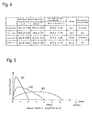
- the confirmation tests are performed under the condition where the seal ring is fitted in the casing 9 and the liner 15 is installed and under the test conditions as described in Fig 5(b) .
- the rotation speed of the liner is 3.8 m/s at the outer periphery of the liner 15; the working pressure on the front face side A is higher than that on the back face side B, by 0.15MPa; the front face side space is filled with fresh water and the back face side space is filled with oil.
- the amount of leakage from the front face side to the back face side, the contact width of the sliding/contacting surface, the wear condition of the sliding/contacting surface and the deformation of the lip part are investigated.
- the first embodiment 1 is a case where the offset 47 regarding the ringed spring 41 is 0.5 mm under a condition that the back-up member 49 is provided.
- the scale m (cf. Fig. 3 ) is set as approximately 4 mm, while the length in the shaft axial direction regarding the arm part 33 is approximately 11 mm.
- the offset 47 regarding the ringed spring 41 is 1.0 mm; and, other items in the second embodiment are the same as the corresponding items in the first embodiment.
- the back-up member 49 is omitted: apart from this omission, the setting conditions are the same as the corresponding conditions in the second embodiment.
- the offset 47 regarding the ringed spring 41 is 2.0 mm; and, the back-up member 49 is provided.
- the setting conditions are the same as the corresponding conditions in the example 5 except that the back-up member 49 is omitted.
- the contacting surface width X is 4 mm; thereby, as shown by the curve S2 in Fig. 6 , the contact pressure in the neighborhood of the lip tip is weakened; thus, sealing performance is deteriorated, and there happens an apprehension that the contact pressure distribution seems to become flat and abnormal wear in an early stage may be caused.
- the result simply due to the difference between the case (i.e. the comparison example 4) without the back-up member and the case (i.e. the second embodiment) with the back-up member is revealed.
- the parameter H3/L4 equals to 14 x 10-4 (in mm-1) ; on the other hand, in the comparison example 4 where the back-up member 49 is not provided, the parameter H3/L4 becomes 4.6 x 10⁻⁴ (in mm-1) .
- the back-up member 49 when the back-up member 49 is omitted, the length L becomes longer, and the parameter H3/L4 becomes smaller than 10 x 10-4 (in mm-1), the contact pressure in the is weakened; and the weakened contact pressure distributes in a wide range; thus, the sealing performance is deteriorated, and there happens an apprehension that the contact pressure distribution seems to become flat and abnormal wear in an early stage may be caused.
- the fitting performance of the seal ring 11a is enhanced; further, the deformation of the key part 29 is restrained; the deformation of the lip part 35 due to the deformation of the key part 29 is also restrained.
- the contact stress in the lip part 35 maintained so that reverse effects on the sealing performance can be evaded.
- seal ring 11a can be easily thrust and fitted in the annular groove 27 in the casing 9; and, the replacement regarding the seal rings 11a, 11b and 11c can be performed on the outer periphery of the liner (or the propeller shaft) without pulling-out the propeller shaft 5.
- the key part 29 is fitted in the annular groove 27; further, when the lip part 35 is set on the outer periphery of the liner 15 so as to keep tight contact with the liner 15, the ringed spring 41 is placed at a position nearer to the inboard side than the lip tip 39 (in the propeller shaft axis direction) by an offset that is established within approximately 20% of the orthogonal projection length of the lip back width 45 onto the propeller shaft axis direction.
- the contact pressure in the neighborhood of the lip-tip 39 is enhanced and the sealing performance of the lip part 35 can be enhanced.
- the contact pressure (stress) in the neighborhood of the lip tip is enhanced, the flat (and wide) contact on the lip back side can be hard to appear; thus, the abnormal wear can be prevented from occurring.
- the contact pressure in the neighborhood of the lip-tip 39 is enhanced, the sealing performance can be enhanced, the contact stress in the lip part 35 can be appropriately maintained so that neither leakage nor abnormal wear in an early stage appears, and durability can be enhanced without spoiling sealing performance.
Landscapes
- Engineering & Computer Science (AREA)
- General Engineering & Computer Science (AREA)
- Mechanical Engineering (AREA)
- Chemical & Material Sciences (AREA)
- Combustion & Propulsion (AREA)
- Ocean & Marine Engineering (AREA)
- Physics & Mathematics (AREA)
- Fluid Mechanics (AREA)
- Sealing With Elastic Sealing Lips (AREA)
- Sealing Devices (AREA)
Claims (7)
- Ein Dichtungsring (11a, 11b, 11c), der zwischen einem Gehäuseelement (9), das auf der Außenbordseite des Heckrohrs (7) vorgesehen ist, und einer Schiffsantriebswelle (5) vorgesehen ist, dringt in den Innenraum des Gehäuseelements (9) vor, derart dass der Dichtungsring Meerwasser vom Eintreten auf der Innenbordseite abhält, wobei der Dichtungsring in einer Querschnittsansicht des Dichtungsrings in einer Ebene, die die Achse der Schiffsantriebswelle umfasst, Folgendes umfasst:einen Schlüsselteil (29), der in eine ringförmige Rille (27) eingepasst ist, die im Gehäuse gebildet ist;einen Absatzteil (31), der sich vom Schlüsselteil zur Zentralachse der Schiffsantriebswelle erstreckt, in der radialen Richtung;einen Armteil (33), der sich von einem inneren Endteil des Absatzteils zur Vorderoberflächenseite des Dichtungsrings mit einem vorbestimmten Kegelwinkel (θ) erstreckt, wobei die Innenumfangsseite des Armteils von einem Sicherungselement (49) unterstützt wird, das auf der Seite des Gehäuseelements gebildet ist;einen Lippenteil (35), der an einem Vorderendteil des Armteils gebildet ist, wobei der Lippenteil an einem Kontaktpunkt einen dichten Kontakt mit der Außenumfangsoberfläche einer Auskleidung (15), die um die Außenumfangsoberfläche der Schiffsantriebswelle herum oder auf dieser aufgesetzt ist, behält;wobei ein Scheitelteil des Schlüsselteils (29) derart geformt ist, dass das Querschnittsprofil hinsichtlich des Scheitelteils eine umgekehrte V-Form nach außen hin in der radialen Richtung bildet; dadurch wird der Scheitel (T) der umgekehrten V-Form in einer Ebene, die die Breite des Schlüsselteils in der Längsrichtung entlang der Schiffsantriebswelle in gleiche Teile aufteilt, gebildet;dadurch gekennzeichnet, dass:- ein Stufenteil (37a) auf der Vorderoberflächenseite des Schlüsselteils und ein Stufenteil (37b) auf der Rückoberflächenseite des Schlüsselteils vorgesehen sind, derart dass die Breite des Dichtungsrings in der axialen Richtung der Schiffsantriebswelle im Übergangsbereich vom Schlüsselteil (29) zum Absatzteil (31) schmaler wird; dabei der Innendurchmesser des Schlüsselteils am Stufenteil auf der Rückoberflächenseite des Schlüsselteils größer als der Innendurchmesser des Schlüsselteils am Stufenteil auf der Vorderoberflächenseite des Schlüsselteils ist, sodass sich ein Raum (N) in der radialen Richtung zwischen dem Stufenteil (37b) auf der Rückflächenseite und der ringförmigen Rille (27) bildet, wenn der Schlüsselteil (29) in der ringförmigen Rille eingesetzt ist;- eine Lippenspitze (39) des Lippenteils (35) eine V-Form, die nach innen in der radialen Richtung herausragt, und eine Federrille (43) mit einem halbkreisförmigen Querschnitt, in welcher eine Ringfeder (41) im Lippenteil gebildet ist, die den Lippenteil zur Schiffsantriebswelle drückt, bildet; dabei das Zentrum (P) hinsichtlich der Federrille derart angeordnet ist, dass es näher an der Innenbordseite als die Position der Lippenspitze (39) um einen Offset in der Richtung der Schiffsantriebswellenachse ist, wobei der Offset innerhalb von etwa 10% der Länge einer Orthogonalprojektion der hinteren Lippenbreite (45) ist, wobei die Orthogonalprojektion eine Projektion auf die Achsrichtung der Schiffsantriebswelle ist; und- ein Lippenvorderflächenwinkel β ein Kegelwinkel ist, den die Lippenvorderfläche mit der Richtung der Schiffsantriebswellenachse zur Lippenvorderseite hin bildet, und ein Lippenrückflächenwinkel α ein Kegelwinkel ist, den die Lippenrückfläche mit der Richtung der Schiffsantriebswellenachse zur Lippenrückseite hin bildet; wobei die Winkel α und β derart ausgebildet sind, dass β > α, β = 45 bis 55° und α = 25 bis 30° sind.
- Dichtungsring nach Anspruch 1, wobei eine Armdicke H eine Dicke des Armteils (33) an einem Kontaktpunkt hinsichtlich des Armteils und des Sicherungselements (49) ist und eine Armlänge L eine Länge entlang einer Kegelwinkelrichtung vom Kontaktpunkt bis zur Lippenspitze (39) ist,
wobei
die Armdicke H und die Armlänge L derart ausgebildet sind, dass eine Relation H3/L4 = (10 bis 30) x 10-4 (in mm-1) gilt. - Dichtungsring nach Anspruch 1, wobei die Steifigkeit des Armteils (33) und des Lippenteils (35) derart ausgebildet ist, dass die Kontaktoberflächenbreite in der Nähe der Lippenspitze (39) 2 bis 3 mm wird, wenn der Druck auf der Vorderflächenseite um 0,15 MPa höher als der Druck auf der Rückflächenseite ist, unter einer Bedingung, dass der Schlüsselteil (29) in der ringförmigen Rille gefasst ist, die Auskleidung installiert ist und der Lippenteil (35) einen dichten Kontakt mit dem Außenumfang der Auskleidung (15), die um die Außenumfangsoberfläche der Schiffsantriebswelle (5) herum oder auf dieser aufgesetzt ist, behält.
- Vorrichtung (1) zur Abdichtung eines Heckrohrs, umfassend:einen Dichtungsring (11a, 11b, 11c), der zwischen einem Gehäuseelement (9), das auf der Außenbordseite des Heckrohrs (7) vorgesehen ist, und einer Schiffsantriebswelle (5) vorgesehen ist, der in den Innenraum des Gehäuseelements (9) vordringt, derart dass der Dichtungsring Meerwasser vom Eintreten auf der Innenbordseite abhält, wobei der Dichtungsring in einer Querschnittsansicht des Dichtungsrings in einer Ebene, die die Achse der Schiffsantriebswelle umfasst, Folgendes umfasst:einen Schlüsselteil (29), der in eine ringförmige Rille (27) eingepasst ist, die im Gehäuse gebildet ist;einen Absatzteil (31), der sich vom Schlüsselteil zur Zentralachse der Schiffsantriebswelle erstreckt, in der radialen Richtung;einen Armteil (33), der sich von einem inneren Endteil des Absatzteils zur Vorderoberflächenseite des Dichtungsrings mit einem vorbestimmten Kegelwinkel erstreckt, wobei die Innenumfangsseite des Armteils von einem Sicherungselement unterstützt wird, das auf der Seite des Gehäuseelements gebildet ist;einen Lippenteil (35), der an einem Vorderendteil des Armteils gebildet ist, wobei der Lippenteil an einem Kontaktpunkt einen dichten Kontakt mit der Außenumfangsoberfläche einer Auskleidung (15), die um die Außenumfangsoberfläche der Schiffsantriebswelle herum oder auf dieser aufgesetzt ist, behält,dadurch gekennzeichnet, dass:- ein Scheitelteil des Schlüsselteils (29) derart geformt ist, dass das Querschnittsprofil hinsichtlich des Scheitelteils eine umgekehrte V-Form nach außen hin in der radialen Richtung bildet; dadurch der Scheitel der umgekehrten V-Form in einer Ebene, die die Breite des Schlüsselteils in der Längsrichtung entlang der Schiffsantriebswelle in gleiche Teile aufteilt, gebildet wird;- ein Stufenteil (37a) auf der Vorderoberflächenseite des Schlüsselteils und ein Stufenteil (37b) auf der Rückoberflächenseite des Schlüsselteils vorgesehen sind, derart dass die Breite des Dichtungsrings in der axialen Richtung der Schiffsantriebswelle im Übergangsbereich vom Schlüsselteil (29) zum Absatzteil (31) schmaler wird; dabei der Innendurchmesser des Schlüsselteils am Stufenteil auf der Rückoberflächenseite des Schlüsselteils größer als der Innendurchmesser des Schlüsselteils am Stufenteil auf der Vorderoberflächenseite des Schlüsselteils ist, sodass sich ein Raum (N) in der radialen Richtung zwischen dem Stufenteil (37b) auf der Rückflächenseite und der ringförmigen Rille (27) bildet, wenn der Schlüsselteil (29) in der ringförmigen Rille eingesetzt ist;- eine Lippenspitze (39) des Lippenteils (35) eine V-Form, die nach innen in der radialen Richtung herausragt, und eine Federrille (43) mit einem halbkreisförmigen Querschnitt, in welcher eine Ringfeder (41) im Lippenteil gebildet ist, die den Lippenteil zur Schiffsantriebswelle drückt, bildet; dabei das Zentrum hinsichtlich der Federrille derart angeordnet ist, dass es näher an der Innenbordseite als die Position der Lippenspitze (39) um einen Offset in der Richtung der Schiffsantriebswellenachse ist, wobei der Offset innerhalb von etwa 10% der Länge einer Orthogonalprojektion der hinteren Lippenbreite (45) ist, wobei die Orthogonalprojektion eine Projektion auf die Achsrichtung der Schiffsantriebswelle ist; und- ein Lippenvorderflächenwinkel β ein Kegelwinkel ist, den die Lippenvorderfläche mit der Richtung der Schiffsantriebswellenachse zur Lippenvorderseite hin bildet, und ein Lippenrückflächenwinkel α ein Kegelwinkel ist, den die Lippenrückfläche mit der Richtung der Schiffsantriebswellenachse zur Lippenrückseite hin bildet; wobei die Winkel α und β derart ausgebildet sind, dass β > α, β = 45 bis 55° und α = 25 bis 30° sind.
- Vorrichtung zur Abdichtung eines Heckrohrs nach Anspruch 4, wobei eine Armdicke H eine Dicke des Armteils (33) an einem Kontaktpunkt hinsichtlich des Armteils (33) und des Sicherungselements (49) ist und eine Armlänge L eine Länge entlang einer Kegelwinkelrichtung vom Kontaktpunkt bis zur Lippenspitze (39) ist,
wobei
die Armdicke H und die Armlänge L derart ausgebildet sind, dass eine Relation H3/L4 = (10 bis 30) x 10-4 (in mm-1) gilt. - Vorrichtung zur Abdichtung eines Heckrohrs nach Anspruch 4, wobei die Steifigkeit des Armteils (33) und des Lippenteils (35) derart ausgebildet ist, dass die Kontaktoberflächenbreite in der Nähe der Lippenspitze (39) 2 bis 3 mm wird, wenn der Druck auf der Vorderflächenseite um 0,15 MPa höher als der Druck auf der Rückflächenseite ist, unter einer Bedingung, dass der Schlüsselteil (29) in der ringförmigen Rille gefasst ist, die Auskleidung installiert ist und der Lippenteil (35) einen dichten Kontakt mit dem Außenumfang der Auskleidung (15), die um die Außenumfangsoberfläche der Schiffsantriebswelle (5) herum oder auf dieser aufgesetzt ist, behält.
- Vorrichtung zur Abdichtung eines Heckrohrs nach Anspruch 4, wobei eine Entlastungsrille (53) in der Nähe einer jeden Mittenposition in der radialen Richtung auf den beiden Seiten der ringförmigen Rille (27) gebildet ist.
Applications Claiming Priority (1)
| Application Number | Priority Date | Filing Date | Title |
|---|---|---|---|
| PCT/JP2010/059880 WO2011155049A1 (ja) | 2010-06-10 | 2010-06-10 | シールリングおよび船尾管シール装置 |
Publications (3)
| Publication Number | Publication Date |
|---|---|
| EP2410216A1 EP2410216A1 (de) | 2012-01-25 |
| EP2410216A4 EP2410216A4 (de) | 2013-11-06 |
| EP2410216B1 true EP2410216B1 (de) | 2014-12-31 |
Family
ID=44080019
Family Applications (1)
| Application Number | Title | Priority Date | Filing Date |
|---|---|---|---|
| EP10798945.1A Active EP2410216B1 (de) | 2010-06-10 | 2010-06-10 | Dichtungsring und vorrichtung zur abdichtung eines heckrohrs |
Country Status (6)
| Country | Link |
|---|---|
| US (1) | US8348281B2 (de) |
| EP (1) | EP2410216B1 (de) |
| JP (1) | JP4673452B1 (de) |
| KR (1) | KR101121210B1 (de) |
| CN (1) | CN102388245B (de) |
| WO (1) | WO2011155049A1 (de) |
Families Citing this family (23)
| Publication number | Priority date | Publication date | Assignee | Title |
|---|---|---|---|---|
| JP5351909B2 (ja) * | 2011-01-21 | 2013-11-27 | バルチラジャパン株式会社 | シール装置 |
| US9261139B2 (en) * | 2013-02-06 | 2016-02-16 | Trelleborg Sealing Solutions Us | Friction-reducing geometric surface feature |
| NL2010322C2 (en) * | 2013-02-18 | 2014-08-21 | Asgard B V | Combination of a ship and an annular lip seal, an annular lip seal, method for replacing an annular lip seal. |
| US20150014937A1 (en) * | 2013-03-07 | 2015-01-15 | Rolls-Royce Corporation | Seal assembly and shaft therefor |
| US9869394B2 (en) * | 2013-10-22 | 2018-01-16 | Skf Marine Gmbh | Sealing system and sealing ring |
| JP6215720B2 (ja) * | 2014-01-24 | 2017-10-18 | 三菱重工業株式会社 | 船尾管シール装置及びこれを備える船舶 |
| JP5897693B2 (ja) * | 2014-03-25 | 2016-03-30 | 三菱電線工業株式会社 | 軸密封構造 |
| TWI736124B (zh) * | 2014-04-17 | 2021-08-11 | 新加坡商肯發系統私人有限公司 | 用於密封地結合相對流體導管端口之環形襯墊及形成一高純度流體接頭之方法 |
| JP6518406B2 (ja) * | 2014-04-30 | 2019-05-22 | Ntn株式会社 | 円すいころ軸受 |
| DE102014210129A1 (de) * | 2014-05-27 | 2015-12-03 | Aktiebolaget Skf | Dichtungsvorrichtung und Verfahren zum Abdichten in einem flüssigen Medium |
| DE102014223064B4 (de) * | 2014-11-12 | 2019-07-18 | Aktiebolaget Skf | Schutzvorrichtung für die Stevenrohrabdichtung von propellerangetriebenen Schiffen |
| WO2016108591A1 (ko) * | 2014-12-29 | 2016-07-07 | 씰링크 주식회사 | 구동축용 밀폐장치 |
| CN107207084B (zh) * | 2016-01-15 | 2018-08-07 | 瓦锡兰日本有限公司 | 船尾管密封系统、船尾管密封装置、船舶及船尾管密封方法 |
| CN106768655B (zh) * | 2016-12-25 | 2023-04-28 | 山西汾西重工有限责任公司 | 航行器推进段动密封测试装置及其测试方法 |
| IT201800004699A1 (it) * | 2018-04-19 | 2019-10-19 | Guarnizione d'emergenza | |
| JP6548238B1 (ja) * | 2018-05-29 | 2019-07-24 | みづほ工業株式会社 | 回転シャフトにおける密封構造、及び撹拌装置 |
| KR101995781B1 (ko) * | 2018-11-23 | 2019-07-03 | (주)한국알앤드디 | 소형 선박 추진기용 부유물 유입방지장치 |
| JP7732623B2 (ja) * | 2019-05-17 | 2025-09-02 | イーグル工業株式会社 | シール装置 |
| KR102632641B1 (ko) * | 2019-09-12 | 2024-02-02 | 항저우 엘에이치디 인스티튜트 오브 뉴 에너지, 엘엘씨 | 해양에너지 발전장치의 밀폐시스템 |
| IT202000015814A1 (it) * | 2020-07-01 | 2022-01-01 | Skf Ab | Dispositivo di tenuta per unità cuscinetto |
| US11703063B2 (en) * | 2020-11-25 | 2023-07-18 | Viking Pump, Inc. | Pump gland with rotary dynamic seal |
| KR102467954B1 (ko) * | 2022-09-01 | 2022-11-17 | 주식회사 유강티에스 | 선미관 수밀 장치 |
| US20240209946A1 (en) * | 2022-12-22 | 2024-06-27 | Flowserve Management Company | Tiltable floating lip seal |
Family Cites Families (18)
| Publication number | Priority date | Publication date | Assignee | Title |
|---|---|---|---|---|
| US3902726A (en) * | 1974-03-15 | 1975-09-02 | Chuetsu Waukesha Co Ltd | Stern tube sealing device |
| US4344631A (en) * | 1980-11-18 | 1982-08-17 | Mechanical Technology Incorporated | Pressure insensitive lip seal |
| JPS59165300U (ja) * | 1983-04-21 | 1984-11-06 | 三菱重工業株式会社 | 船尾管軸封装置 |
| US4534569A (en) * | 1983-09-27 | 1985-08-13 | Mitsubishi Jukogyo Kabushiki Kaisha | Stern tube seal device providing a seal about a rotatable shaft |
| DE3804284A1 (de) * | 1987-12-23 | 1989-07-13 | Goetze Ag | Wellendichtring |
| JPH0298092A (ja) * | 1988-10-04 | 1990-04-10 | Ricoh Co Ltd | 白色薄膜エレクトロルミネッセント素子 |
| JPH0732391Y2 (ja) * | 1989-01-25 | 1995-07-26 | イーグル工業株式会社 | 船尾管軸封装置 |
| DE4141999C2 (de) * | 1991-12-19 | 1997-06-12 | Blohm Voss Ag | Lippendichtung zum Abdichten einer Welle, insbesondere einer Schiffspropellerwelle |
| JP2588024Y2 (ja) * | 1992-06-25 | 1999-01-06 | 日本マリンテクノ株式会社 | 船尾管シール装置 |
| JPH06323443A (ja) | 1993-05-10 | 1994-11-25 | Mitsubishi Heavy Ind Ltd | 船尾管軸封装置用端面密封型シールリング |
| DE4434261B4 (de) * | 1994-09-24 | 2004-07-08 | B + V Industrietechnik Gmbh | Anlage zur Anpassung an den wechselnden Tiefgang von Seeschiffen |
| JPH0972427A (ja) * | 1995-09-04 | 1997-03-18 | Nippon Marine Techno Kk | 船尾管シール装置 |
| JP2000110946A (ja) * | 1998-10-06 | 2000-04-18 | Koyo Sealing Techno Co Ltd | 密封装置 |
| JP4109374B2 (ja) | 1999-02-23 | 2008-07-02 | バルチラジャパン株式会社 | 船尾管シール装置 |
| JP2001066757A (ja) * | 2000-08-07 | 2001-03-16 | Seiko Epson Corp | 露光方法 |
| JP2002276817A (ja) * | 2001-03-21 | 2002-09-25 | Nok Corp | 密封装置 |
| JP2003120823A (ja) * | 2001-10-19 | 2003-04-23 | Eagle Ind Co Ltd | シール装置 |
| US7798496B2 (en) * | 2003-11-05 | 2010-09-21 | Kalsi Engineering, Inc. | Rotary shaft sealing assembly |
-
2010
- 2010-06-10 EP EP10798945.1A patent/EP2410216B1/de active Active
- 2010-06-10 JP JP2010545314A patent/JP4673452B1/ja active Active
- 2010-06-10 CN CN201080002328.7A patent/CN102388245B/zh active Active
- 2010-06-10 WO PCT/JP2010/059880 patent/WO2011155049A1/ja not_active Ceased
- 2010-06-10 KR KR1020117002269A patent/KR101121210B1/ko active Active
-
2011
- 2011-01-28 US US13/016,489 patent/US8348281B2/en active Active
Also Published As
| Publication number | Publication date |
|---|---|
| US20110304102A1 (en) | 2011-12-15 |
| EP2410216A4 (de) | 2013-11-06 |
| WO2011155049A1 (ja) | 2011-12-15 |
| US8348281B2 (en) | 2013-01-08 |
| KR101121210B1 (ko) | 2012-03-22 |
| CN102388245A (zh) | 2012-03-21 |
| EP2410216A1 (de) | 2012-01-25 |
| JPWO2011155049A1 (ja) | 2013-08-01 |
| KR20110138208A (ko) | 2011-12-26 |
| JP4673452B1 (ja) | 2011-04-20 |
| CN102388245B (zh) | 2014-08-27 |
Similar Documents
| Publication | Publication Date | Title |
|---|---|---|
| EP2410216B1 (de) | Dichtungsring und vorrichtung zur abdichtung eines heckrohrs | |
| EP1625897B1 (de) | Lagerdichtung mit flexibler Lippe | |
| KR20120091392A (ko) | 스프링-활성화된 동적 실링 조립체를 위한 시스템, 방법 및 장치 | |
| US8141880B2 (en) | High pressure sealing apparatus | |
| US20150176651A1 (en) | Seal unit for rolling-element bearing and rolling-element bearing including the seal unit | |
| EP1941188A2 (de) | Abdichtung zur anwendung mit rohr- und flanschbaugruppen | |
| US10871231B2 (en) | Sealing device | |
| WO2014091930A1 (ja) | シール構造 | |
| EP1538376B1 (de) | Dichtungsvorrichtung | |
| US20140377057A1 (en) | Sealing device | |
| JP2017180534A (ja) | リップシール及び密封構造 | |
| EP3060831B1 (de) | Dichtungssystem und dichtungsring | |
| JP6606685B2 (ja) | 船尾管シール装置及び船尾管密封構造 | |
| JP5869382B2 (ja) | 船尾管シール装置 | |
| GB2375149A (en) | A gasket | |
| JP6589155B2 (ja) | 船尾管用シールリング及び船尾管密封構造 | |
| US20250060006A1 (en) | Bearing seal and its application | |
| JP2021050754A (ja) | ガスケット | |
| US20220128153A1 (en) | Face seal having elastomeric ring with surface shape for improved sealing | |
| JP2018080732A (ja) | 密封装置 | |
| HK1228484A1 (en) | Sealing system and sealing ring |
Legal Events
| Date | Code | Title | Description |
|---|---|---|---|
| PUAI | Public reference made under article 153(3) epc to a published international application that has entered the european phase |
Free format text: ORIGINAL CODE: 0009012 |
|
| 17P | Request for examination filed |
Effective date: 20110119 |
|
| AK | Designated contracting states |
Kind code of ref document: A1 Designated state(s): AL AT BE BG CH CY CZ DE DK EE ES FI FR GB GR HR HU IE IS IT LI LT LU LV MC MK MT NL NO PL PT RO SE SI SK SM TR |
|
| DAX | Request for extension of the european patent (deleted) | ||
| A4 | Supplementary search report drawn up and despatched |
Effective date: 20131004 |
|
| RIC1 | Information provided on ipc code assigned before grant |
Ipc: B63H 23/32 20060101ALI20130927BHEP Ipc: F16J 15/32 20060101AFI20130927BHEP Ipc: B63H 23/36 20060101ALI20130927BHEP Ipc: F16J 15/40 20060101ALI20130927BHEP Ipc: F16J 15/18 20060101ALI20130927BHEP |
|
| GRAP | Despatch of communication of intention to grant a patent |
Free format text: ORIGINAL CODE: EPIDOSNIGR1 |
|
| INTG | Intention to grant announced |
Effective date: 20140716 |
|
| GRAS | Grant fee paid |
Free format text: ORIGINAL CODE: EPIDOSNIGR3 |
|
| GRAA | (expected) grant |
Free format text: ORIGINAL CODE: 0009210 |
|
| AK | Designated contracting states |
Kind code of ref document: B1 Designated state(s): AL AT BE BG CH CY CZ DE DK EE ES FI FR GB GR HR HU IE IS IT LI LT LU LV MC MK MT NL NO PL PT RO SE SI SK SM TR |
|
| REG | Reference to a national code |
Ref country code: CH Ref legal event code: EP Ref country code: GB Ref legal event code: FG4D |
|
| REG | Reference to a national code |
Ref country code: IE Ref legal event code: FG4D |
|
| REG | Reference to a national code |
Ref country code: AT Ref legal event code: REF Ref document number: 704618 Country of ref document: AT Kind code of ref document: T Effective date: 20150215 |
|
| REG | Reference to a national code |
Ref country code: DE Ref legal event code: R096 Ref document number: 602010021498 Country of ref document: DE Effective date: 20150226 |
|
| REG | Reference to a national code |
Ref country code: NL Ref legal event code: T3 |
|
| PG25 | Lapsed in a contracting state [announced via postgrant information from national office to epo] |
Ref country code: LT Free format text: LAPSE BECAUSE OF FAILURE TO SUBMIT A TRANSLATION OF THE DESCRIPTION OR TO PAY THE FEE WITHIN THE PRESCRIBED TIME-LIMIT Effective date: 20141231 Ref country code: FI Free format text: LAPSE BECAUSE OF FAILURE TO SUBMIT A TRANSLATION OF THE DESCRIPTION OR TO PAY THE FEE WITHIN THE PRESCRIBED TIME-LIMIT Effective date: 20141231 Ref country code: NO Free format text: LAPSE BECAUSE OF FAILURE TO SUBMIT A TRANSLATION OF THE DESCRIPTION OR TO PAY THE FEE WITHIN THE PRESCRIBED TIME-LIMIT Effective date: 20150331 |
|
| REG | Reference to a national code |
Ref country code: LT Ref legal event code: MG4D |
|
| PG25 | Lapsed in a contracting state [announced via postgrant information from national office to epo] |
Ref country code: LV Free format text: LAPSE BECAUSE OF FAILURE TO SUBMIT A TRANSLATION OF THE DESCRIPTION OR TO PAY THE FEE WITHIN THE PRESCRIBED TIME-LIMIT Effective date: 20141231 Ref country code: GR Free format text: LAPSE BECAUSE OF FAILURE TO SUBMIT A TRANSLATION OF THE DESCRIPTION OR TO PAY THE FEE WITHIN THE PRESCRIBED TIME-LIMIT Effective date: 20150401 Ref country code: HR Free format text: LAPSE BECAUSE OF FAILURE TO SUBMIT A TRANSLATION OF THE DESCRIPTION OR TO PAY THE FEE WITHIN THE PRESCRIBED TIME-LIMIT Effective date: 20141231 Ref country code: SE Free format text: LAPSE BECAUSE OF FAILURE TO SUBMIT A TRANSLATION OF THE DESCRIPTION OR TO PAY THE FEE WITHIN THE PRESCRIBED TIME-LIMIT Effective date: 20141231 |
|
| REG | Reference to a national code |
Ref country code: AT Ref legal event code: MK05 Ref document number: 704618 Country of ref document: AT Kind code of ref document: T Effective date: 20141231 |
|
| PG25 | Lapsed in a contracting state [announced via postgrant information from national office to epo] |
Ref country code: CZ Free format text: LAPSE BECAUSE OF FAILURE TO SUBMIT A TRANSLATION OF THE DESCRIPTION OR TO PAY THE FEE WITHIN THE PRESCRIBED TIME-LIMIT Effective date: 20141231 Ref country code: ES Free format text: LAPSE BECAUSE OF FAILURE TO SUBMIT A TRANSLATION OF THE DESCRIPTION OR TO PAY THE FEE WITHIN THE PRESCRIBED TIME-LIMIT Effective date: 20141231 Ref country code: RO Free format text: LAPSE BECAUSE OF FAILURE TO SUBMIT A TRANSLATION OF THE DESCRIPTION OR TO PAY THE FEE WITHIN THE PRESCRIBED TIME-LIMIT Effective date: 20141231 Ref country code: SK Free format text: LAPSE BECAUSE OF FAILURE TO SUBMIT A TRANSLATION OF THE DESCRIPTION OR TO PAY THE FEE WITHIN THE PRESCRIBED TIME-LIMIT Effective date: 20141231 |
|
| PG25 | Lapsed in a contracting state [announced via postgrant information from national office to epo] |
Ref country code: IS Free format text: LAPSE BECAUSE OF FAILURE TO SUBMIT A TRANSLATION OF THE DESCRIPTION OR TO PAY THE FEE WITHIN THE PRESCRIBED TIME-LIMIT Effective date: 20150430 Ref country code: AT Free format text: LAPSE BECAUSE OF FAILURE TO SUBMIT A TRANSLATION OF THE DESCRIPTION OR TO PAY THE FEE WITHIN THE PRESCRIBED TIME-LIMIT Effective date: 20141231 Ref country code: PL Free format text: LAPSE BECAUSE OF FAILURE TO SUBMIT A TRANSLATION OF THE DESCRIPTION OR TO PAY THE FEE WITHIN THE PRESCRIBED TIME-LIMIT Effective date: 20141231 |
|
| REG | Reference to a national code |
Ref country code: DE Ref legal event code: R097 Ref document number: 602010021498 Country of ref document: DE |
|
| PG25 | Lapsed in a contracting state [announced via postgrant information from national office to epo] |
Ref country code: DK Free format text: LAPSE BECAUSE OF FAILURE TO SUBMIT A TRANSLATION OF THE DESCRIPTION OR TO PAY THE FEE WITHIN THE PRESCRIBED TIME-LIMIT Effective date: 20141231 Ref country code: EE Free format text: LAPSE BECAUSE OF FAILURE TO SUBMIT A TRANSLATION OF THE DESCRIPTION OR TO PAY THE FEE WITHIN THE PRESCRIBED TIME-LIMIT Effective date: 20141231 |
|
| PLBE | No opposition filed within time limit |
Free format text: ORIGINAL CODE: 0009261 |
|
| STAA | Information on the status of an ep patent application or granted ep patent |
Free format text: STATUS: NO OPPOSITION FILED WITHIN TIME LIMIT |
|
| 26N | No opposition filed |
Effective date: 20151001 |
|
| PG25 | Lapsed in a contracting state [announced via postgrant information from national office to epo] |
Ref country code: IT Free format text: LAPSE BECAUSE OF FAILURE TO SUBMIT A TRANSLATION OF THE DESCRIPTION OR TO PAY THE FEE WITHIN THE PRESCRIBED TIME-LIMIT Effective date: 20141231 |
|
| PG25 | Lapsed in a contracting state [announced via postgrant information from national office to epo] |
Ref country code: MC Free format text: LAPSE BECAUSE OF FAILURE TO SUBMIT A TRANSLATION OF THE DESCRIPTION OR TO PAY THE FEE WITHIN THE PRESCRIBED TIME-LIMIT Effective date: 20141231 |
|
| REG | Reference to a national code |
Ref country code: CH Ref legal event code: PL |
|
| PG25 | Lapsed in a contracting state [announced via postgrant information from national office to epo] |
Ref country code: LU Free format text: LAPSE BECAUSE OF FAILURE TO SUBMIT A TRANSLATION OF THE DESCRIPTION OR TO PAY THE FEE WITHIN THE PRESCRIBED TIME-LIMIT Effective date: 20150610 Ref country code: SI Free format text: LAPSE BECAUSE OF FAILURE TO SUBMIT A TRANSLATION OF THE DESCRIPTION OR TO PAY THE FEE WITHIN THE PRESCRIBED TIME-LIMIT Effective date: 20141231 |
|
| REG | Reference to a national code |
Ref country code: IE Ref legal event code: MM4A |
|
| REG | Reference to a national code |
Ref country code: FR Ref legal event code: ST Effective date: 20160229 |
|
| PG25 | Lapsed in a contracting state [announced via postgrant information from national office to epo] |
Ref country code: CH Free format text: LAPSE BECAUSE OF NON-PAYMENT OF DUE FEES Effective date: 20150630 Ref country code: IE Free format text: LAPSE BECAUSE OF NON-PAYMENT OF DUE FEES Effective date: 20150610 Ref country code: LI Free format text: LAPSE BECAUSE OF NON-PAYMENT OF DUE FEES Effective date: 20150630 |
|
| PG25 | Lapsed in a contracting state [announced via postgrant information from national office to epo] |
Ref country code: BE Free format text: LAPSE BECAUSE OF FAILURE TO SUBMIT A TRANSLATION OF THE DESCRIPTION OR TO PAY THE FEE WITHIN THE PRESCRIBED TIME-LIMIT Effective date: 20141231 Ref country code: FR Free format text: LAPSE BECAUSE OF NON-PAYMENT OF DUE FEES Effective date: 20150630 |
|
| PG25 | Lapsed in a contracting state [announced via postgrant information from national office to epo] |
Ref country code: MT Free format text: LAPSE BECAUSE OF FAILURE TO SUBMIT A TRANSLATION OF THE DESCRIPTION OR TO PAY THE FEE WITHIN THE PRESCRIBED TIME-LIMIT Effective date: 20141231 |
|
| PG25 | Lapsed in a contracting state [announced via postgrant information from national office to epo] |
Ref country code: SM Free format text: LAPSE BECAUSE OF FAILURE TO SUBMIT A TRANSLATION OF THE DESCRIPTION OR TO PAY THE FEE WITHIN THE PRESCRIBED TIME-LIMIT Effective date: 20141231 Ref country code: BG Free format text: LAPSE BECAUSE OF FAILURE TO SUBMIT A TRANSLATION OF THE DESCRIPTION OR TO PAY THE FEE WITHIN THE PRESCRIBED TIME-LIMIT Effective date: 20141231 Ref country code: HU Free format text: LAPSE BECAUSE OF FAILURE TO SUBMIT A TRANSLATION OF THE DESCRIPTION OR TO PAY THE FEE WITHIN THE PRESCRIBED TIME-LIMIT; INVALID AB INITIO Effective date: 20100610 |
|
| PG25 | Lapsed in a contracting state [announced via postgrant information from national office to epo] |
Ref country code: CY Free format text: LAPSE BECAUSE OF FAILURE TO SUBMIT A TRANSLATION OF THE DESCRIPTION OR TO PAY THE FEE WITHIN THE PRESCRIBED TIME-LIMIT Effective date: 20141231 |
|
| PG25 | Lapsed in a contracting state [announced via postgrant information from national office to epo] |
Ref country code: TR Free format text: LAPSE BECAUSE OF FAILURE TO SUBMIT A TRANSLATION OF THE DESCRIPTION OR TO PAY THE FEE WITHIN THE PRESCRIBED TIME-LIMIT Effective date: 20141231 |
|
| PG25 | Lapsed in a contracting state [announced via postgrant information from national office to epo] |
Ref country code: MK Free format text: LAPSE BECAUSE OF FAILURE TO SUBMIT A TRANSLATION OF THE DESCRIPTION OR TO PAY THE FEE WITHIN THE PRESCRIBED TIME-LIMIT Effective date: 20141231 |
|
| PG25 | Lapsed in a contracting state [announced via postgrant information from national office to epo] |
Ref country code: PT Free format text: LAPSE BECAUSE OF FAILURE TO SUBMIT A TRANSLATION OF THE DESCRIPTION OR TO PAY THE FEE WITHIN THE PRESCRIBED TIME-LIMIT Effective date: 20141231 |
|
| PG25 | Lapsed in a contracting state [announced via postgrant information from national office to epo] |
Ref country code: AL Free format text: LAPSE BECAUSE OF FAILURE TO SUBMIT A TRANSLATION OF THE DESCRIPTION OR TO PAY THE FEE WITHIN THE PRESCRIBED TIME-LIMIT Effective date: 20141231 |
|
| PGFP | Annual fee paid to national office [announced via postgrant information from national office to epo] |
Ref country code: NL Payment date: 20250528 Year of fee payment: 16 |
|
| PGFP | Annual fee paid to national office [announced via postgrant information from national office to epo] |
Ref country code: DE Payment date: 20250617 Year of fee payment: 16 |
|
| PGFP | Annual fee paid to national office [announced via postgrant information from national office to epo] |
Ref country code: GB Payment date: 20250625 Year of fee payment: 16 |