EP2409926A1 - Pouring device designed to be inserted in the outlet nozzle of a receptacle, in particular of a bottle - Google Patents
Pouring device designed to be inserted in the outlet nozzle of a receptacle, in particular of a bottle Download PDFInfo
- Publication number
- EP2409926A1 EP2409926A1 EP11174589A EP11174589A EP2409926A1 EP 2409926 A1 EP2409926 A1 EP 2409926A1 EP 11174589 A EP11174589 A EP 11174589A EP 11174589 A EP11174589 A EP 11174589A EP 2409926 A1 EP2409926 A1 EP 2409926A1
- Authority
- EP
- European Patent Office
- Prior art keywords
- unitary element
- asperities
- unitary
- liquid
- wound
- Prior art date
- Legal status (The legal status is an assumption and is not a legal conclusion. Google has not performed a legal analysis and makes no representation as to the accuracy of the status listed.)
- Granted
Links
- 239000007788 liquid Substances 0.000 claims abstract description 31
- 239000000463 material Substances 0.000 claims abstract description 12
- 238000005273 aeration Methods 0.000 claims abstract description 10
- 238000004804 winding Methods 0.000 claims abstract description 6
- 239000008188 pellet Substances 0.000 claims description 15
- 230000015572 biosynthetic process Effects 0.000 claims description 3
- 230000003247 decreasing effect Effects 0.000 claims description 3
- 238000010008 shearing Methods 0.000 claims description 3
- 206010000496 acne Diseases 0.000 claims 1
- 229940082150 encore Drugs 0.000 description 3
- 235000010603 pastilles Nutrition 0.000 description 3
- 238000003756 stirring Methods 0.000 description 3
- 240000008042 Zea mays Species 0.000 description 2
- 239000000470 constituent Substances 0.000 description 2
- 238000012423 maintenance Methods 0.000 description 2
- 230000002411 adverse Effects 0.000 description 1
- 229910052782 aluminium Inorganic materials 0.000 description 1
- XAGFODPZIPBFFR-UHFFFAOYSA-N aluminium Chemical compound [Al] XAGFODPZIPBFFR-UHFFFAOYSA-N 0.000 description 1
- 235000019568 aromas Nutrition 0.000 description 1
- 238000003490 calendering Methods 0.000 description 1
- 230000000295 complement effect Effects 0.000 description 1
- 238000009826 distribution Methods 0.000 description 1
- 230000000694 effects Effects 0.000 description 1
- 238000005516 engineering process Methods 0.000 description 1
- 210000003746 feather Anatomy 0.000 description 1
- 239000000796 flavoring agent Substances 0.000 description 1
- 235000019634 flavors Nutrition 0.000 description 1
- 239000012530 fluid Substances 0.000 description 1
- 239000011888 foil Substances 0.000 description 1
- 238000007373 indentation Methods 0.000 description 1
- 238000003780 insertion Methods 0.000 description 1
- 230000037431 insertion Effects 0.000 description 1
- 230000014759 maintenance of location Effects 0.000 description 1
- 238000004519 manufacturing process Methods 0.000 description 1
- 239000007769 metal material Substances 0.000 description 1
- 238000000034 method Methods 0.000 description 1
- 238000006213 oxygenation reaction Methods 0.000 description 1
- 230000001737 promoting effect Effects 0.000 description 1
- 238000004080 punching Methods 0.000 description 1
- 230000003746 surface roughness Effects 0.000 description 1
Images


Classifications
-
- B—PERFORMING OPERATIONS; TRANSPORTING
- B65—CONVEYING; PACKING; STORING; HANDLING THIN OR FILAMENTARY MATERIAL
- B65D—CONTAINERS FOR STORAGE OR TRANSPORT OF ARTICLES OR MATERIALS, e.g. BAGS, BARRELS, BOTTLES, BOXES, CANS, CARTONS, CRATES, DRUMS, JARS, TANKS, HOPPERS, FORWARDING CONTAINERS; ACCESSORIES, CLOSURES, OR FITTINGS THEREFOR; PACKAGING ELEMENTS; PACKAGES
- B65D23/00—Details of bottles or jars not otherwise provided for
- B65D23/06—Integral drip catchers or drip-preventing means
- B65D23/065—Loose or loosely-attached drip catchers or drip preventing means
-
- B—PERFORMING OPERATIONS; TRANSPORTING
- B65—CONVEYING; PACKING; STORING; HANDLING THIN OR FILAMENTARY MATERIAL
- B65D—CONTAINERS FOR STORAGE OR TRANSPORT OF ARTICLES OR MATERIALS, e.g. BAGS, BARRELS, BOTTLES, BOXES, CANS, CARTONS, CRATES, DRUMS, JARS, TANKS, HOPPERS, FORWARDING CONTAINERS; ACCESSORIES, CLOSURES, OR FITTINGS THEREFOR; PACKAGING ELEMENTS; PACKAGES
- B65D47/00—Closures with filling and discharging, or with discharging, devices
- B65D47/40—Closures with filling and discharging, or with discharging, devices with drip catchers or drip-preventing means
Definitions
- the present invention relates to a pouring device for insertion into an outlet end of a container, in particular a bottle.
- the pouring device of the aforementioned document is constituted by an elastic and transparent unitary element, with a geometry of its free edge which is chosen to avoid the final dripping at the end of the pouring operation of the liquid, when the bottle is raised.
- the aforementioned pouring device was improved, opting for a realization in the form of a circular disk so as to form a free edge better adapted to the shearing of the drops, and with an inner surface to both smooth and repulsive for liquids and low surface adhesion for the liquid in question to effectively prevent drops from traveling down the edge of the outlet port on the outside of the bottle or of the container upon completion of the spill, that is, when the bottle is returned to the upright position.
- the document EP-0 560 777 B1 please refer to the document EP-0 560 777 B1 .
- the object of the invention is to further improve the above-mentioned pouring devices, keeping the concept of a flexible and elastic element wound cylindrically on itself, but able to intervene actively on the liquid to be poured during the passage of the latter. ci through the pouring device.
- the invention particularly relates to a pouring device promoting the development of the flavors of the liquid, in particular a wine or a liquor.
- a pouring device intended to be inserted into an outlet end of a container, in particular of a bottle, said device being constituted by a unitary element of a material made of sheet both flexible to allow a cylindrical winding of said element on itself and elastic to allow a hold in place in the outlet tip by the only contact force exerted by the outer surface of said wound element, the inner surface of said wound element forming to its free edge a flow guide for the liquid to be poured, said pouring device being remarkable in that the inner surface of the unitary element is at least partially bristled with at least one roughness that provides aeration of the liquid during the payment thereof.
- the liquid when the container, in particular the bottle, is inclined to proceed to the pouring of the liquid, the liquid necessarily passes on the roughness or asperities bristling the inner surface of the unitary element, and undergoes a slight stirring which provides aeration of the liquid, that is to say an oxygenation, when the payment thereof.
- this or these asperities should be arranged for the stirring procured remains light, so as not to cause any creation of bubbles or excessive movements that would adversely affect the organoleptic properties of the liquid.
- the inner surface of the unitary element is in all bristling with one or more asperities, or alternatively is partly only bristling with one or more asperities, preferably then on the only part that extends to beyond the outlet mouthpiece when said device is put in place.
- the asperities of the inner surface of the unitary element are of point type, being constituted by a plurality of pellets or pins in relief.
- the asperities of the inner surface of the unitary element are of substantially continuous type, being constituted by at least one geometrical pattern or figurative relief.
- the inner surface of the unitary element is bristled with a single asperity, in particular in the form of bulge or rib.
- the above-mentioned pellets, pins, relief pattern, bulge or rib are added elements, whether or not they are of the same material as that constituting the unitary element, or alternatively, are local deformations of unitary element.
- the asperities of the inner surface of the unitary element are constituted by a plurality of punctures.
- the punctures have a substantially triangular shape with an upwardly pointed tip, or alternatively have an elongated bar shape.
- the asperities of the inner surface of the unitary element are arranged in a predetermined pattern, regular or not.
- the asperities of the inner surface of the unitary element all protrude by the same distance in height.
- these asperities protrude different distances in height, in particular increasing or decreasing distances in the liquid flow direction.
- the unitary element has a triangular general shape with axial symmetry, the axis of symmetry being a generatrix of the unitary element wound cylindrically on itself, the tip of the triangle constituting the end of the edge. free of said element.
- the unitary element has a generally asymmetrical shape, with a tip constituting the end of the free edge said element.
- the unitary element has a transverse dimension which is sufficient to ensure overlapping of the two lateral edges when said wound element is in place in the outlet nozzle.
- the unit element has a slightly rounded tip geometry to promote the shear formation of liquid drops.
- the unitary element carries a printed pattern on its inner surface and / or outer, or in the mass of said element.
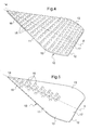
- FIG 1 there is a pouring device according to the invention, which is intended to be inserted into an outlet tip of a container, in particular a bottle. It is represented on this figure in its free state, not coiled, so essentially flat, while on the Figures 2A and 2B the same device is shown rolled cylindrically on itself, that is to say after lifting the lateral edges 13 of the unitary element 10, as shown schematically by the arrows 100 of the figure 1 .
- the pouring device is constituted by a unitary element denoted 10 of a sheet material both flexible to allow a cylindrical winding of said element on itself and elastic to allow a retention in place in the outlet end by the single contact force exerted by the outer surface denoted 12 of said wound element, the interior surface denoted 11 of said wound element forming to its free edge denoted 16 a flow guide for the liquid to pour.
- the Figure 2A illustrates precisely the pouring device thus designed, once it is wound on itself and inserted into an outlet tip, in this case the neck 1 of a bottle, in which it is held in place by its own elasticity own .
- a rear part rated 17 of the element unitary 10 is inserted inside the bottle neck 1, the rear portion for ensuring the holding in place of said unitary element rolled cylindrically on itself.
- the portion that protrudes from the edge 2 of the neck 1 constitutes the centerpiece of the pouring device, which operates functionally on the liquid to be poured to the free edge 16 and the pointed tip 14 thereof.
- the free edge 16 may be rectilinear or curved, but it will be advantageous to provide a rounded tip geometry to promote the shearing of liquid drops in formation, in the manner of the flexible anti-drip verses of the prior art.
- the inner surface 11 of the unitary element 10, which is the upper surface in the view of the figure 1 is at least partly bristled with at least one asperity that provides aeration of the liquid during the pouring thereof, as illustrated in Figure 2B .
- the inner surface 11 of the unitary element 10 is partly only bristling with asperities 15, in this case on the only part that extends beyond the neck 1 of the bottle when said device is set up as this is illustrated on the Figures 2A and 2B , so that the inner surface 11 is then perfectly smooth at the rear portion 17.
- the embossed pellets 15 are local deformations of the unitary element 10, which deformations may be for example performed by passing the flexible element between two complementary calendering rollers.
- the asperities are inserts, as is visible for the pellets 15.1, then being or not of the same material as that constituting the unitary element 10.
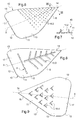
- FIGS. 6 and 7 illustrate another embodiment of the aforementioned asperities, always of point type, which are then constituted by pins noted 15.2. As can be seen on the associated section of the figure 7 the embossed pins 15.2 are associated with local deformations of the outer surface 12 of the unitary element 10.
- the asperities of the inner surface 11 of the unitary element 10 are of the non-point type, but essentially continuous, being for example constituted by a geometric or figurative relief pattern, such as the pattern 15.3 shown here which is a leaf ribbing pattern.
- a slightly different type of stirring will then be obtained, with an active surface that may be greater than that of the abovementioned pellets or pins.
- the figure 8 also illustrates the possibility that the unitary element 10 further carries a pattern printed on its inner surface 11 and / or outer 12, or in the mass of said element.
- This printed pattern, noted A is in this case represented by a series of small circles aligned in a transverse direction.
- the figures 9 and 10 still illustrate other variants in which the asperities of the inner surface 11 of the unitary element 10 are constituted by a plurality of punctures. These punctures result from a punching of the wall constituting the unitary element 10 with tools of shape adapted to the desired shape of the asperities.
- the asperities 15 to 15.5 of the inner surface 11 of the unitary element 10 are each arranged in a predetermined pattern, generally substantially regular. This is of course only one example, and we can provide a more random distribution depending on the desired aeration effect.
- the asperities 15 to 15.5 of the inner surface 11 of the unitary element 10 all protrude by the same distance in height.
- varying heights for example increasing or decreasing in the direction of flow of the liquid (variations not illustrated here), may be provided.
- the figure 11 illustrates another variant in which the inner surface 11 of the unitary element 10 is bristling with a single roughness 15.6, in particular in the form of bulge or rib as is visible here.
- thermoformable plastic material will be used as the constituent material, and a thickness of 10 to 12 tenths of a millimeter may then be provided.
- Any type of plastic or metal material likely to be suitable for the application in question, in particular PET, or coated aluminum foils may be used as the constituent material.
- the unitary element 10 has a triangular general shape with axial symmetry, the axis of symmetry denoted X being a generatrix of the unitary element wound cylindrically on itself, the rounded tip 14 of the triangle then forming the end of the edge 16 of said element, in the manner of a feather writing.
- the lateral edges 13 of the unitary element 10 are raised as shown by the arrows 100 on the figure 1 for winding said element on itself, on either side of the axis of symmetry X, to then arrive at the conformation illustrated on the Figures 2A and 2B .
- the unitary element has a transverse dimension which is sufficient to ensure overlapping of the two lateral edges 13 when said wound element is in place in the endpiece. of exit, as is visible on the Figures 2A and 2B .
- the presence of this overlap zone is a guarantee of a sufficient reserve of elasticity which contributes to the natural maintenance of the unitary element wound on itself in the bottle neck.
- the pouring device of the invention is also extremely simple in structure and easy to manufacture under economically interesting conditions.
- the asperities of aeration may be constituted by surface roughness.
Abstract
Description
La présente invention concerne un dispositif verseur destiné à être inséré dans un embout de sortie d'un récipient, en particulier d'une bouteille.The present invention relates to a pouring device for insertion into an outlet end of a container, in particular a bottle.
Il y a une cinquantaine d'années, il a été conçu un dispositif verseur du type constitué par un élément unitaire d'une matière en feuille à la fois souple pour permettre un enroulement cylindrique dudit élément sur lui-même et élastique pour permettre un maintien en place dans l'embout de sortie par la seule force de contact exercée par la surface extérieure dudit élément enroulé, la surface intérieure dudit élément enroulé formant jusqu'à son bord libre un guide d'écoulement pour le liquide à verser. On pourra à ce titre se référer au document
Le dispositif verseur du document précité est constitué par un élément unitaire élastique et transparent, avec une géométrie de son bord libre qui est choisie pour éviter le dégouttement final à la fin de l'opération de versage du liquide, lorsque la bouteille est relevée.The pouring device of the aforementioned document is constituted by an elastic and transparent unitary element, with a geometry of its free edge which is chosen to avoid the final dripping at the end of the pouring operation of the liquid, when the bottle is raised.
On pourra également se référer à d'autres documents concernant des dispositifs verseurs, en particulier aux documents
Il y a une quinzaine d'années, le dispositif verseur précité a été perfectionné, en optant pour une réalisation sous la forme d'un disque circulaire de façon à former un bord libre mieux adapté au cisaillage des gouttes, et avec une surface interne à la fois lisse et répulsive pour les liquides et une faible adhérence de surface pour le liquide en question afin d'empêcher efficacement les gouttes de cheminer vers le bas du bord de l'orifice de sortie à l'extérieur de la bouteille ou du récipient lors de l'achèvement du déversement, c'est-à-dire lorsque la bouteille est remise en position verticale. On pourra à ce titre se référer au document
Des agencements analogues sous forme de disques non plus circulaires, mais en forme de cardioïde ou de pointe de flèche ou de disque encoché, ont été également proposés (on pourra se référer aux documents
L'invention a pour objet d'améliorer encore les dispositifs verseur précités, en gardant le concept d'un élément souple et élastique enroulé cylindriquement sur lui-même, mais capable d'intervenir activement sur le liquide à verser lors du passage de celui-ci au travers du dispositif verseur.The object of the invention is to further improve the above-mentioned pouring devices, keeping the concept of a flexible and elastic element wound cylindrically on itself, but able to intervene actively on the liquid to be poured during the passage of the latter. ci through the pouring device.
L'invention a en particulier pour objet un dispositif verseur favorisant le développement des arômes du liquide, en particulier d'un vin ou d'une liqueur.The invention particularly relates to a pouring device promoting the development of the flavors of the liquid, in particular a wine or a liquor.
Le problème technique précité est résolu conformément à l'invention grâce à un dispositif verseur destiné à être inséré dans un embout de sortie d'un récipient, en particulier d'une bouteille, ledit dispositif étant constitué par un élément unitaire d'une matière en feuille à la fois souple pour permettre un enroulement cylindrique dudit élément sur lui-même et élastique pour permettre un maintien en place dans l'embout de sortie par la seule force de contact exercée par la surface extérieure dudit élément enroulé, la surface intérieure dudit élément enroulé formant jusqu'à son bord libre un guide d'écoulement pour le liquide à verser, ledit dispositif verseur étant remarquable en ce que la surface intérieure de l'élément unitaire est au moins en partie hérissée d'au moins une aspérité qui procure une aération du liquide lors du versement de celui-ci.The aforementioned technical problem is solved according to the invention by means of a pouring device intended to be inserted into an outlet end of a container, in particular of a bottle, said device being constituted by a unitary element of a material made of sheet both flexible to allow a cylindrical winding of said element on itself and elastic to allow a hold in place in the outlet tip by the only contact force exerted by the outer surface of said wound element, the inner surface of said wound element forming to its free edge a flow guide for the liquid to be poured, said pouring device being remarkable in that the inner surface of the unitary element is at least partially bristled with at least one roughness that provides aeration of the liquid during the payment thereof.
Ainsi, lorsque le récipient, en particulier la bouteille, est incliné pour procéder au versage du liquide, le liquide passe nécessairement sur la ou les aspérités hérissant la surface intérieure de l'élément unitaire, et subit ainsi un léger brassage qui procure une aération du liquide, c'est-à-dire une oxygénation, lors du versement de celui-ci. Bien entendu, comme cela sera précisé plus loin, cette ou ces aspérités devront être agencées pour que le brassage procuré reste léger, afin de ne pas provoquer une quelconque création de bulles ou de mouvements excessifs qui nuiraient aux propriétés organoleptiques du liquide.Thus, when the container, in particular the bottle, is inclined to proceed to the pouring of the liquid, the liquid necessarily passes on the roughness or asperities bristling the inner surface of the unitary element, and undergoes a slight stirring which provides aeration of the liquid, that is to say an oxygenation, when the payment thereof. Of course, as will be specified later, this or these asperities should be arranged for the stirring procured remains light, so as not to cause any creation of bubbles or excessive movements that would adversely affect the organoleptic properties of the liquid.
On pourra prévoir que la surface intérieure de l'élément unitaire est en totalité hérissée d'une ou plusieurs aspérités, ou en variante est en partie seulement hérissée d'une ou plusieurs aspérités, de préférence alors sur la seule partie qui s'étend au-delà de l'embout de sortie lorsque ledit dispositif est mis en place.It can be provided that the inner surface of the unitary element is in all bristling with one or more asperities, or alternatively is partly only bristling with one or more asperities, preferably then on the only part that extends to beyond the outlet mouthpiece when said device is put in place.
Conformément à un mode de réalisation particulier, les aspérités de la surface intérieure de l'élément unitaire sont de type ponctuel, en étant constituées par une pluralité de pastilles ou de picots en relief.According to a particular embodiment, the asperities of the inner surface of the unitary element are of point type, being constituted by a plurality of pellets or pins in relief.
Conformément à un autre mode de réalisation, les aspérités de la surface intérieure de l'élément unitaire sont de type essentiellement continu, en étant constituées par au moins un motif géométrique ou figuratif en relief.According to another embodiment, the asperities of the inner surface of the unitary element are of substantially continuous type, being constituted by at least one geometrical pattern or figurative relief.
Conformément à encore un autre mode de réalisation, la surface intérieure de l'élément unitaire est hérissée d'une unique aspérité, en particulier en forme de bombement ou de nervure.According to still another embodiment, the inner surface of the unitary element is bristled with a single asperity, in particular in the form of bulge or rib.
De préférence, les pastilles, picots, motif en relief, bombement ou nervure précités sont des éléments rapportés, en étant ou non de même matière que celle constituant l'élément unitaire, ou en variante, sont des déformations locales de d'élément unitaire.Preferably, the above-mentioned pellets, pins, relief pattern, bulge or rib are added elements, whether or not they are of the same material as that constituting the unitary element, or alternatively, are local deformations of unitary element.
Conformément à encore un autre mode de réalisation, les aspérités de la surface intérieure de l'élément unitaire sont constituées par une pluralité de crevés. En particulier, les crevés ont une forme essentiellement triangulaire à pointe tournée vers le haut, ou en variante ont une forme de barrette allongée.According to still another embodiment, the asperities of the inner surface of the unitary element are constituted by a plurality of punctures. In particular, the punctures have a substantially triangular shape with an upwardly pointed tip, or alternatively have an elongated bar shape.
D'une façon générale, on pourra éventuellement prévoir que les aspérités de la surface intérieure de l'élément unitaire sont disposées selon une trame prédéterminée, régulière ou non.In general, it may be possible to provide that the asperities of the inner surface of the unitary element are arranged in a predetermined pattern, regular or not.
En particulier, les aspérités de la surface intérieure de l'élément unitaire saillent toutes de la même distance en hauteur. En variante, on pourra prévoir que ces aspérités saillent de distances différentes en hauteur, en particulier de distances croissantes ou décroissantes dans la direction de circulation du liquide.In particular, the asperities of the inner surface of the unitary element all protrude by the same distance in height. Alternatively, it can be provided that these asperities protrude different distances in height, in particular increasing or decreasing distances in the liquid flow direction.
Dans un mode de réalisation particulier, l'élément unitaire a une forme générale triangulaire à symétrie axiale, l'axe de symétrie étant une génératrice de l'élément unitaire enroulé cylindriquement sur lui-même, la pointe du triangle constituant l'extrémité du bord libre dudit élément. En variante, on pourra prévoir que l'élément unitaire a une forme générale asymétrique, avec une pointe constituant l'extrémité du bord libre dudit élément.In a particular embodiment, the unitary element has a triangular general shape with axial symmetry, the axis of symmetry being a generatrix of the unitary element wound cylindrically on itself, the tip of the triangle constituting the end of the edge. free of said element. Alternatively, it can be provided that the unitary element has a generally asymmetrical shape, with a tip constituting the end of the free edge said element.
Avantageusement alors, l'élément unitaire présente une dimension transversale qui est suffisante pour assurer un recouvrement des deux bords latéraux lorsque ledit élément enroulé est en place dans l'embout de sortie.Advantageously then, the unitary element has a transverse dimension which is sufficient to ensure overlapping of the two lateral edges when said wound element is in place in the outlet nozzle.
On pourra également prévoir que l'élément unitaire présente une géométrie de pointe légèrement arrondie pour favoriser le cisaillement des gouttes de liquide en formation.It can also be provided that the unit element has a slightly rounded tip geometry to promote the shear formation of liquid drops.
Avantageusement enfin, il pourra s'avérer intéressant de prévoir que l'élément unitaire porte un motif imprimé sur sa surface intérieure et/ou extérieure, ou dans la masse dudit élément.Advantageously finally, it may be advantageous to provide that the unitary element carries a printed pattern on its inner surface and / or outer, or in the mass of said element.
D'autres caractéristiques et avantages de l'invention apparaîtront plus clairement à la lumière de la description qui va suivre et des dessins annexés concernant des modes de réalisation particuliers de l'invention donnés à titre d'exemple.Other features and advantages of the invention will emerge more clearly in the light of the following description and the accompanying drawings relating to particular embodiments of the invention given by way of example.
Il sera fait référence aux figures du dessin annexé où :
- la
figure 1 illustre en perspective un dispositif verseur conforme à l'invention, dans son état à plat, permettant de distinguer les aspérités, ici sous forme de pastilles, qui hérissent la surface supérieure de l'élément unitaire constituant ledit dispositif (qui deviendra la surface intérieure de l'élément unitaire lorsque celui-ci est enroulé cylindriquement) ; - les
figures 2A et 2B illustrent le dispositif verseur enroulé cylindriquement sur lui-même et mis en place dans un goulot de bouteille (figure 2A ), ledit dispositif étant alors prêt à fonctionner de manière opérationnelle, en procurant une aération du liquide lors du versement de celui-ci (figure 2B ) ; - la
figure 3A est une coupe selon III-III de lafigure 1 , permettant de mieux distinguer les enfoncements localisés de la paroi de l'élément unitaire au niveau des pastilles constituant les aspérités d'aération ; - la
figure 3B est une variante de lafigure 3A , illustrant des pastilles de forme analogue, mais rapportées sur la paroi principale ; - la
figure 4 illustre une variante du dispositif verseur précité, dans laquelle la surface intérieure de l'élément unitaire est en totalité hérissée d'aspérités ; - la
figure 5 illustre encore une autre variante dans laquelle une partie seulement de la surface intérieure de l'élément unitaire est hérissée d'aspérités ; - la
figure 6 illustre en perspective une autre variante dans laquelle les aspérités de la surface intérieure de l'élément unitaire sont constituées par des picots en relief ; - la
figure 7 est une coupe selon VII-VII de lafigure 6 , permettant de mieux distinguer les enfoncements localisés de la paroi de l'élément unitaire, au niveau des picots ; - la
figure 8 illustre encore une autre variante du dispositif verseur, dans laquelle les aspérités ne sont plus de type essentiellement ponctuel, mais de type continu, en étant par exemple constituées par un motif géométrique ou figuratif en relief, ici en forme de nervurage de feuille, cette figure illustrant également la présence optionnelle d'un motif imprimé, en particulier publicitaire ; - la
figure 9 illustre une autre variante du dispositif verseur dans laquelle les aspérités sont constituées par des crevés, ici de forme triangulaire à pointe tournée vers le haut ; - la
figure 10 illustre une variante du dispositif de lafigure 9 , dans laquelle les crevés ont une forme de barrette allongée ; et - la
figure 11 illustre encore une autre variante du dispositif verseur, dans laquelle il est prévu une unique aspérité, ici en forme de bombement.
- the
figure 1 illustrates in perspective a pouring device according to the invention, in its flat state, to distinguish the asperities, here in the form of pellets, which bristle the upper surface of the unit element constituting said device (which will become the inner surface of the unitary element when it is rolled cylindrically); - the
Figures 2A and 2B illustrate the pouring device wound cylindrically on itself and placed in a bottleneck (Figure 2A ), said device then being ready to operate in an operational manner, by providing aeration of the liquid during the pouring thereof (Figure 2B ); - the
figure 3A is a section III-III of thefigure 1 , making it possible to better distinguish the localized depressions of the wall of the unitary element at the level of the pellets constituting the asperities of aeration; - the
figure 3B is a variant of thefigure 3A , illustrating pellets of similar shape, but reported on the main wall; - the
figure 4 illustrates a variant of the aforementioned pouring device, in which the inner surface of the unitary element is in all bristling with asperities; - the
figure 5 illustrates yet another variant in which only a portion of the inner surface of the unitary element is bristling with asperities; - the
figure 6 illustrates in perspective another variant in which the asperities of the inner surface of the unitary element are constituted by raised pins; - the
figure 7 is a section according to VII-VII of thefigure 6 , making it possible to better distinguish the localized depressions of the wall of the unitary element, at the level of the pins; - the
figure 8 illustrates yet another variant of the pouring device, in which the asperities are no longer of essentially point type, but of continuous type, being for example constituted by a geometric or figurative relief pattern, here in the form of leaf ribbing, this figure also illustrating the optional presence of a printed motif, in particular advertising; - the
figure 9 illustrates another variant of the pouring device in which the asperities are constituted by punctured, here of triangular shape with tip upwards; - the
figure 10 illustrates a variant of the device of thefigure 9 wherein the punctures have an elongated bar shape; and - the
figure 11 illustrates yet another variant of the pouring device, in which there is provided a single asperity, here in the form of a bulge.
Sur la
Conformément à la technique intérieure bien connue depuis une cinquantaine d'années, le dispositif verseur est constitué par un élément unitaire noté 10 d'une matière en feuille à la fois souple pour permettre un enroulement cylindrique dudit élément sur lui-même et élastique pour permettre un maintien en place dans l'embout de sortie par la seule force de contact exercée par la surface extérieure notée 12 dudit élément enroulé, la surface intérieure notée 11 dudit élément enroulé formant jusqu'à son bord libre noté 16 un guide d'écoulement pour le liquide à verser.In accordance with the well-known interior technique for about fifty years, the pouring device is constituted by a unitary element denoted 10 of a sheet material both flexible to allow a cylindrical winding of said element on itself and elastic to allow a retention in place in the outlet end by the single contact force exerted by the outer surface denoted 12 of said wound element, the interior surface denoted 11 of said wound element forming to its free edge denoted 16 a flow guide for the liquid to pour.
La
En effet, et conformément à la technologie classique, une partie arrière notée 17 de l'élément unitaire 10 est insérée à l'intérieure du goulot de bouteille 1, cette partie arrière servant à assurer le maintien en place dudit élément unitaire enroulé cylindriquement sur lui-même. La partie qui dépasse du bord 2 du goulot 1 constitue la pièce maîtresse du dispositif verseur, qui intervient fonctionnellement sur le liquide à verser jusqu'au bord libre 16 et à la pointe notée 14 de celui-ci. Le bord libre 16 peut être rectiligne ou incurvé, mais il sera avantageux de prévoir une géométrie de pointe arrondie pour favoriser le cisaillement des gouttes de liquide en formation, à la manière des verseurs souples anti-gouttes de la technique antérieure.Indeed, and in accordance with conventional technology, a rear part rated 17 of the element unitary 10 is inserted inside the
Conformément à une caractéristique essentielle de l'invention, la surface intérieure 11 de l'élément unitaire 10, qui est la surface supérieure sur la vue de la
On distingue ainsi sur la
On constate sur la
Comme cela est mieux visible sur la coupe associée de la
En variante, et comme illustré sur la
Lorsqu'il s'agit d'enfoncements de la paroi extérieure 12 comme cela est illustré sur la
Sur la
Sur la
Les
Sur la
La
Les
Sur la
Dans le cas d'une réalisation d'aspérités sous la forme de crevés, il sera préférable de prévoir de tels crevés sur la seule partie de l'élément unitaire 10 qui s'étend au-delà de l'embout de sortie, afin d'éviter tout risque de fuite de liquide le long de la surface interne du goulot, comme déjà mentionné plus haut. La partie arrière 17 de l'élément unitaire 10 est alors exempte de crevés.In the case of a realization of asperities in the form of punctures, it will be preferable to provide such punctures on the only part of the
Dans tous les exemples qui ont été mentionnés plus haut, les aspérités 15 à 15.5 de la surface intérieure 11 de l'élément unitaire 10 sont à chaque fois disposées selon une trame prédéterminée, en général essentiellement régulière. Ceci ne constitue bien sûr qu'un exemple, et on pourra prévoir une distribution plus aléatoire en fonction de l'effet d'aération recherché.In all the examples which have been mentioned above, the
Il sera en général prévu que les aspérités 15 à 15.5 de la surface intérieure 11 de l'élément unitaire 10 saillent toutes de la même distance en hauteur. En variante, on pourra prévoir des hauteurs variables, par exemple croissantes ou décroissantes dans la direction de circulation du liquide (variantes non illustrées ici).It will generally be provided that the
La
D'une façon générale, on utilisera comme matière constitutive une matière plastique thermoformable, et on pourra alors prévoir une épaisseur de 10 à 12 dixièmes de millimètre. On pourra utiliser comme matériau constitutif tout type de matériau plastique ou métallique susceptible de convenir à l'application concernée, en particulier PET, ou des feuilles d'aluminium enrobées.In general, a thermoformable plastic material will be used as the constituent material, and a thickness of 10 to 12 tenths of a millimeter may then be provided. Any type of plastic or metal material likely to be suitable for the application in question, in particular PET, or coated aluminum foils may be used as the constituent material.
Dans tous les modes de réalisations précédemment décrits, on a pu observer que l'élément unitaire 10 a une forme générale triangulaire à symétrie axiale, l'axe de symétrie noté X étant une génératrice de l'élément unitaire enroulé cylindriquement sur lui-même, la pointe arrondie 14 du triangle constituant alors l'extrémité du bord 16 dudit élément, à la manière d'une plume d'écriture. Dans ce cas, les bords latéraux 13 de l'élément unitaire 10 sont relevés comme cela est figuré par les flèches 100 sur la
Il ne s'agit cependant que d'une variante préférée, étant entendu que l'on pourra utiliser des formes différentes, en particulier une forme générale asymétrique, ou encore des formes à bord libre arrondi et non en forme de pointe, comme cela est déjà bien connu de le prévoir (variantes non illustrées ici).However, this is only a preferred variant, it being understood that it will be possible to use different shapes, in particular an asymmetrical general shape, or else shapes with a free rounded edge and not a point-like shape, as is the case here. already well known to foresee it (variants not illustrated here).
D'une façon générale, quelle que soit la forme choisie, il sera préférable de prévoir que l'élément unitaire présente une dimension transversale qui est suffisante pour assurer un recouvrement des deux bords latéraux 13 lorsque ledit élément enroulé est en place dans l'embout de sortie, comme cela est visible sur les
On ainsi parvenu à réaliser un dispositif verseur souple capable d'assurer, en plus d'une fonction anti-goutte bien connue, une fonction d'aération douce du liquide lors du versement de celui-ci, tout en évitant naturellement un brassage violent qui casserait les arômes du liquide.It has thus been possible to produce a flexible pouring device capable of providing, in addition to a well-known anti-drip function, a function of gentle aeration of the liquid during the pouring thereof, while of course avoiding violent mixing which break the aromas of the liquid.
Le dispositif verseur de l'invention est en outre de structure extrêmement simple et aisé à fabriquer dans des conditions économiquement intéressantes.The pouring device of the invention is also extremely simple in structure and easy to manufacture under economically interesting conditions.
On est donc en particulier très loin des tentatives passées de réaliser un dispositif verseur rigide enveloppant un venturi pour générer un écoulement turbulent du liquide versé.It is therefore in particular very far from past attempts to achieve a rigid pouring device enveloping a venturi to generate a flow turbulent liquid poured.
L'invention n'est pas limitée aux modes de réalisation qui viennent d'être décrits, mais englobe au contraire toutes variantes reprenant, avec des moyens équivalents, les caractéristiques essentielles énoncées plus haut.The invention is not limited to the embodiments which have just been described, but on the contrary covers all variants using, with equivalent means, the essential characteristics mentioned above.
En particulier les aspérités d'aération pourront être constituées par des rugosités de surface.In particular the asperities of aeration may be constituted by surface roughness.
Claims (19)
Applications Claiming Priority (1)
| Application Number | Priority Date | Filing Date | Title |
|---|---|---|---|
| FR1055901A FR2962982B1 (en) | 2010-07-20 | 2010-07-20 | A POURING DEVICE FOR INSERTION IN AN EXIT TIP OF A CONTAINER, ESPECIALLY A BOTTLE |
Publications (2)
| Publication Number | Publication Date |
|---|---|
| EP2409926A1 true EP2409926A1 (en) | 2012-01-25 |
| EP2409926B1 EP2409926B1 (en) | 2013-02-20 |
Family
ID=43064361
Family Applications (1)
| Application Number | Title | Priority Date | Filing Date |
|---|---|---|---|
| EP20110174589 Active EP2409926B1 (en) | 2010-07-20 | 2011-07-19 | Pouring device designed to be inserted in the outlet nozzle of a receptacle, in particular of a bottle |
Country Status (3)
| Country | Link |
|---|---|
| EP (1) | EP2409926B1 (en) |
| CN (1) | CN102442464B (en) |
| FR (1) | FR2962982B1 (en) |
Cited By (2)
| Publication number | Priority date | Publication date | Assignee | Title |
|---|---|---|---|---|
| EP2620382A1 (en) * | 2012-01-25 | 2013-07-31 | Schur Pack Denmark a/s | Drip catcher with aerator |
| EP2952441A1 (en) | 2014-06-03 | 2015-12-09 | Brian Vang | A spout for a beverage bottle and a method of producing a spout preform |
Citations (15)
| Publication number | Priority date | Publication date | Assignee | Title |
|---|---|---|---|---|
| SE52197C1 (en) | ||||
| FR589771A (en) | 1924-02-12 | 1925-06-05 | Container for holding and consuming liquids | |
| US1749253A (en) | 1926-02-09 | 1930-03-04 | Levy Leo | Pouring spout |
| GB467339A (en) | 1936-11-16 | 1937-06-16 | William Farquiiarson Ireland | Novel or improved device to facilitate pouring liquid from bottles and other receptacles |
| FR1198362A (en) | 1958-07-01 | 1959-12-07 | Pourer for bottles and similar objects | |
| GB2180817A (en) | 1985-09-23 | 1987-04-08 | Edward Joseph Lagnado | Drip collecting collar for container |
| DE3736245A1 (en) | 1987-10-27 | 1989-05-11 | Eisenmenger Wolfgang | Device for avoiding droplet formation at pouring apertures for liquids |
| EP0329883A1 (en) | 1988-02-25 | 1989-08-30 | Owens-Illinois Plastic Products Inc. | Plastic container with self-draining feature |
| US5121779A (en) | 1990-12-31 | 1992-06-16 | John Green | Funnel |
| WO1995019917A1 (en) | 1994-01-21 | 1995-07-27 | Christensen Jan T Enggaard | Flexible drip-catcher |
| EP0560777B1 (en) | 1990-09-24 | 1997-01-08 | JENSEN, Brian Vang | Drip-catcher |
| US6073816A (en) | 1995-07-26 | 2000-06-13 | Granberg; Preben | Drip-catcher and a method therefor |
| WO2005009850A1 (en) * | 2003-07-31 | 2005-02-03 | De Oliveira Camara Marcia | Insert for beverage cans in general |
| WO2008104010A1 (en) * | 2007-03-01 | 2008-09-04 | Johannes Gumpold | Nozzle |
| WO2009018634A1 (en) * | 2007-08-07 | 2009-02-12 | Camara Marcia De Oliveira | Arrangement introduced in insert for beverage cans |
Family Cites Families (2)
| Publication number | Priority date | Publication date | Assignee | Title |
|---|---|---|---|---|
| DE2308383A1 (en) * | 1973-02-21 | 1974-08-22 | Dieter Anschuetz | ADHESIVE FUNNEL FOR REFILL BAG |
| CN200988616Y (en) * | 2006-08-11 | 2007-12-12 | 邹汛 | Bottle neck attachment |
-
2010
- 2010-07-20 FR FR1055901A patent/FR2962982B1/en not_active Expired - Fee Related
-
2011
- 2011-07-19 EP EP20110174589 patent/EP2409926B1/en active Active
- 2011-07-20 CN CN201110265355.XA patent/CN102442464B/en not_active Expired - Fee Related
Patent Citations (15)
| Publication number | Priority date | Publication date | Assignee | Title |
|---|---|---|---|---|
| SE52197C1 (en) | ||||
| FR589771A (en) | 1924-02-12 | 1925-06-05 | Container for holding and consuming liquids | |
| US1749253A (en) | 1926-02-09 | 1930-03-04 | Levy Leo | Pouring spout |
| GB467339A (en) | 1936-11-16 | 1937-06-16 | William Farquiiarson Ireland | Novel or improved device to facilitate pouring liquid from bottles and other receptacles |
| FR1198362A (en) | 1958-07-01 | 1959-12-07 | Pourer for bottles and similar objects | |
| GB2180817A (en) | 1985-09-23 | 1987-04-08 | Edward Joseph Lagnado | Drip collecting collar for container |
| DE3736245A1 (en) | 1987-10-27 | 1989-05-11 | Eisenmenger Wolfgang | Device for avoiding droplet formation at pouring apertures for liquids |
| EP0329883A1 (en) | 1988-02-25 | 1989-08-30 | Owens-Illinois Plastic Products Inc. | Plastic container with self-draining feature |
| EP0560777B1 (en) | 1990-09-24 | 1997-01-08 | JENSEN, Brian Vang | Drip-catcher |
| US5121779A (en) | 1990-12-31 | 1992-06-16 | John Green | Funnel |
| WO1995019917A1 (en) | 1994-01-21 | 1995-07-27 | Christensen Jan T Enggaard | Flexible drip-catcher |
| US6073816A (en) | 1995-07-26 | 2000-06-13 | Granberg; Preben | Drip-catcher and a method therefor |
| WO2005009850A1 (en) * | 2003-07-31 | 2005-02-03 | De Oliveira Camara Marcia | Insert for beverage cans in general |
| WO2008104010A1 (en) * | 2007-03-01 | 2008-09-04 | Johannes Gumpold | Nozzle |
| WO2009018634A1 (en) * | 2007-08-07 | 2009-02-12 | Camara Marcia De Oliveira | Arrangement introduced in insert for beverage cans |
Cited By (3)
| Publication number | Priority date | Publication date | Assignee | Title |
|---|---|---|---|---|
| EP2620382A1 (en) * | 2012-01-25 | 2013-07-31 | Schur Pack Denmark a/s | Drip catcher with aerator |
| EP2952441A1 (en) | 2014-06-03 | 2015-12-09 | Brian Vang | A spout for a beverage bottle and a method of producing a spout preform |
| WO2015185609A1 (en) | 2014-06-03 | 2015-12-10 | Brian Vang | A spout for a beverage bottle and a method of producing a spout preform |
Also Published As
| Publication number | Publication date |
|---|---|
| CN102442464B (en) | 2014-11-12 |
| FR2962982B1 (en) | 2012-08-10 |
| EP2409926B1 (en) | 2013-02-20 |
| FR2962982A1 (en) | 2012-01-27 |
| CN102442464A (en) | 2012-05-09 |
Similar Documents
| Publication | Publication Date | Title |
|---|---|---|
| EP2385776B1 (en) | Tasting glass | |
| EP0728427A1 (en) | Applicator for cosmetic substances | |
| CA2197083A1 (en) | Variable volume bottle | |
| FR2925263A1 (en) | Support element for cosmetic article, has grid partially extending in cosmetic product block, and cells forming honeycomb configuration, where grid has upper surface formed in convex shape, and lower surface formed in flat shape | |
| CH429480A (en) | Metal closure element for a tubular container | |
| EP2443042A1 (en) | Anti-drip device for a bottle | |
| EP0590105A1 (en) | Break-open phial. | |
| EP2409926B1 (en) | Pouring device designed to be inserted in the outlet nozzle of a receptacle, in particular of a bottle | |
| EP3423368B1 (en) | Capsule made of heat-shrinkable plastic and use of the skirt of a capsule to form a drip-catching pouring spout | |
| EP1210890B1 (en) | Tasting glass | |
| EP2697125A1 (en) | Double-valley petaloid container bottom | |
| FR2898107A1 (en) | Food e.g. meat, packing and selling container, has blind annular cavity limited by peripheral wall of cavity, base of cavity and inner projection, where projection and wall have respective tapers in direction of orifice | |
| CA1235096A (en) | Compliant bag made of synthetic material, and its stiff removable element to stop it up | |
| EP3766806B1 (en) | Container for collecting waste with double lid provided with a device for retaining the lids | |
| EP1166692B1 (en) | Dripless pouring spout | |
| EP2499064B1 (en) | Fluid product dispenser | |
| FR2998878A1 (en) | Covering device for drinking liquid bottle, has sheath sized so as to elastically enclose portion of bottle after device is assembled on bottle, and envelope made of elastic textile material and partially covering outer surface of sheath | |
| FR2613696A1 (en) | Extensible drinking straw for the consumption of drinks and container using it | |
| WO2014091170A1 (en) | Fluid product applicator device | |
| JP2009227329A (en) | Internal plug for liquid dropping | |
| FR2885354A1 (en) | PROTECTION SYSTEM FOR CANETTE | |
| FR3130261A3 (en) | Beverage can transport device | |
| FR3104142A1 (en) | CONTAINER OF THE TYPE WITHOUT LID AND CONTAINER ASSEMBLY METHOD | |
| WO2010112701A1 (en) | Pouring device for oenological use or for tasting a beverage | |
| FR3051340A3 (en) | POT FOR THE PREPARATION OF MILK |
Legal Events
| Date | Code | Title | Description |
|---|---|---|---|
| AK | Designated contracting states |
Kind code of ref document: A1 Designated state(s): AL AT BE BG CH CY CZ DE DK EE ES FI FR GB GR HR HU IE IS IT LI LT LU LV MC MK MT NL NO PL PT RO RS SE SI SK SM TR |
|
| AX | Request for extension of the european patent |
Extension state: BA ME |
|
| PUAI | Public reference made under article 153(3) epc to a published international application that has entered the european phase |
Free format text: ORIGINAL CODE: 0009012 |
|
| 17P | Request for examination filed |
Effective date: 20120627 |
|
| GRAP | Despatch of communication of intention to grant a patent |
Free format text: ORIGINAL CODE: EPIDOSNIGR1 |
|
| RIC1 | Information provided on ipc code assigned before grant |
Ipc: B65D 47/40 20060101ALI20120731BHEP Ipc: B65D 23/06 20060101AFI20120731BHEP |
|
| GRAS | Grant fee paid |
Free format text: ORIGINAL CODE: EPIDOSNIGR3 |
|
| GRAA | (expected) grant |
Free format text: ORIGINAL CODE: 0009210 |
|
| AK | Designated contracting states |
Kind code of ref document: B1 Designated state(s): AL AT BE BG CH CY CZ DE DK EE ES FI FR GB GR HR HU IE IS IT LI LT LU LV MC MK MT NL NO PL PT RO RS SE SI SK SM TR |
|
| REG | Reference to a national code |
Ref country code: GB Ref legal event code: FG4D Free format text: NOT ENGLISH |
|
| REG | Reference to a national code |
Ref country code: CH Ref legal event code: EP |
|
| REG | Reference to a national code |
Ref country code: AT Ref legal event code: REF Ref document number: 597438 Country of ref document: AT Kind code of ref document: T Effective date: 20130315 |
|
| REG | Reference to a national code |
Ref country code: IE Ref legal event code: FG4D Free format text: LANGUAGE OF EP DOCUMENT: FRENCH |
|
| REG | Reference to a national code |
Ref country code: DE Ref legal event code: R096 Ref document number: 602011000926 Country of ref document: DE Effective date: 20130418 |
|
| REG | Reference to a national code |
Ref country code: CH Ref legal event code: NV Representative=s name: BOVARD AG, CH |
|
| REG | Reference to a national code |
Ref country code: AT Ref legal event code: MK05 Ref document number: 597438 Country of ref document: AT Kind code of ref document: T Effective date: 20130220 |
|
| REG | Reference to a national code |
Ref country code: NL Ref legal event code: VDEP Effective date: 20130220 |
|
| REG | Reference to a national code |
Ref country code: LT Ref legal event code: MG4D |
|
| PG25 | Lapsed in a contracting state [announced via postgrant information from national office to epo] |
Ref country code: AT Free format text: LAPSE BECAUSE OF FAILURE TO SUBMIT A TRANSLATION OF THE DESCRIPTION OR TO PAY THE FEE WITHIN THE PRESCRIBED TIME-LIMIT Effective date: 20130220 Ref country code: LT Free format text: LAPSE BECAUSE OF FAILURE TO SUBMIT A TRANSLATION OF THE DESCRIPTION OR TO PAY THE FEE WITHIN THE PRESCRIBED TIME-LIMIT Effective date: 20130220 Ref country code: NO Free format text: LAPSE BECAUSE OF FAILURE TO SUBMIT A TRANSLATION OF THE DESCRIPTION OR TO PAY THE FEE WITHIN THE PRESCRIBED TIME-LIMIT Effective date: 20130520 Ref country code: IS Free format text: LAPSE BECAUSE OF FAILURE TO SUBMIT A TRANSLATION OF THE DESCRIPTION OR TO PAY THE FEE WITHIN THE PRESCRIBED TIME-LIMIT Effective date: 20130620 Ref country code: BG Free format text: LAPSE BECAUSE OF FAILURE TO SUBMIT A TRANSLATION OF THE DESCRIPTION OR TO PAY THE FEE WITHIN THE PRESCRIBED TIME-LIMIT Effective date: 20130520 Ref country code: SE Free format text: LAPSE BECAUSE OF FAILURE TO SUBMIT A TRANSLATION OF THE DESCRIPTION OR TO PAY THE FEE WITHIN THE PRESCRIBED TIME-LIMIT Effective date: 20130220 Ref country code: ES Free format text: LAPSE BECAUSE OF FAILURE TO SUBMIT A TRANSLATION OF THE DESCRIPTION OR TO PAY THE FEE WITHIN THE PRESCRIBED TIME-LIMIT Effective date: 20130531 |
|
| PG25 | Lapsed in a contracting state [announced via postgrant information from national office to epo] |
Ref country code: PL Free format text: LAPSE BECAUSE OF FAILURE TO SUBMIT A TRANSLATION OF THE DESCRIPTION OR TO PAY THE FEE WITHIN THE PRESCRIBED TIME-LIMIT Effective date: 20130220 Ref country code: PT Free format text: LAPSE BECAUSE OF FAILURE TO SUBMIT A TRANSLATION OF THE DESCRIPTION OR TO PAY THE FEE WITHIN THE PRESCRIBED TIME-LIMIT Effective date: 20130620 Ref country code: LV Free format text: LAPSE BECAUSE OF FAILURE TO SUBMIT A TRANSLATION OF THE DESCRIPTION OR TO PAY THE FEE WITHIN THE PRESCRIBED TIME-LIMIT Effective date: 20130220 Ref country code: SI Free format text: LAPSE BECAUSE OF FAILURE TO SUBMIT A TRANSLATION OF THE DESCRIPTION OR TO PAY THE FEE WITHIN THE PRESCRIBED TIME-LIMIT Effective date: 20130220 Ref country code: GR Free format text: LAPSE BECAUSE OF FAILURE TO SUBMIT A TRANSLATION OF THE DESCRIPTION OR TO PAY THE FEE WITHIN THE PRESCRIBED TIME-LIMIT Effective date: 20130521 Ref country code: FI Free format text: LAPSE BECAUSE OF FAILURE TO SUBMIT A TRANSLATION OF THE DESCRIPTION OR TO PAY THE FEE WITHIN THE PRESCRIBED TIME-LIMIT Effective date: 20130220 |
|
| PG25 | Lapsed in a contracting state [announced via postgrant information from national office to epo] |
Ref country code: HR Free format text: LAPSE BECAUSE OF FAILURE TO SUBMIT A TRANSLATION OF THE DESCRIPTION OR TO PAY THE FEE WITHIN THE PRESCRIBED TIME-LIMIT Effective date: 20130220 Ref country code: RS Free format text: LAPSE BECAUSE OF FAILURE TO SUBMIT A TRANSLATION OF THE DESCRIPTION OR TO PAY THE FEE WITHIN THE PRESCRIBED TIME-LIMIT Effective date: 20130220 |
|
| PG25 | Lapsed in a contracting state [announced via postgrant information from national office to epo] |
Ref country code: NL Free format text: LAPSE BECAUSE OF FAILURE TO SUBMIT A TRANSLATION OF THE DESCRIPTION OR TO PAY THE FEE WITHIN THE PRESCRIBED TIME-LIMIT Effective date: 20130220 Ref country code: RO Free format text: LAPSE BECAUSE OF FAILURE TO SUBMIT A TRANSLATION OF THE DESCRIPTION OR TO PAY THE FEE WITHIN THE PRESCRIBED TIME-LIMIT Effective date: 20130220 Ref country code: SK Free format text: LAPSE BECAUSE OF FAILURE TO SUBMIT A TRANSLATION OF THE DESCRIPTION OR TO PAY THE FEE WITHIN THE PRESCRIBED TIME-LIMIT Effective date: 20130220 Ref country code: DK Free format text: LAPSE BECAUSE OF FAILURE TO SUBMIT A TRANSLATION OF THE DESCRIPTION OR TO PAY THE FEE WITHIN THE PRESCRIBED TIME-LIMIT Effective date: 20130220 Ref country code: EE Free format text: LAPSE BECAUSE OF FAILURE TO SUBMIT A TRANSLATION OF THE DESCRIPTION OR TO PAY THE FEE WITHIN THE PRESCRIBED TIME-LIMIT Effective date: 20130220 Ref country code: CZ Free format text: LAPSE BECAUSE OF FAILURE TO SUBMIT A TRANSLATION OF THE DESCRIPTION OR TO PAY THE FEE WITHIN THE PRESCRIBED TIME-LIMIT Effective date: 20130220 |
|
| PLBE | No opposition filed within time limit |
Free format text: ORIGINAL CODE: 0009261 |
|
| STAA | Information on the status of an ep patent application or granted ep patent |
Free format text: STATUS: NO OPPOSITION FILED WITHIN TIME LIMIT |
|
| PG25 | Lapsed in a contracting state [announced via postgrant information from national office to epo] |
Ref country code: IT Free format text: LAPSE BECAUSE OF FAILURE TO SUBMIT A TRANSLATION OF THE DESCRIPTION OR TO PAY THE FEE WITHIN THE PRESCRIBED TIME-LIMIT Effective date: 20130220 |
|
| 26N | No opposition filed |
Effective date: 20131121 |
|
| BERE | Be: lapsed |
Owner name: SANBRI Effective date: 20130731 |
|
| PG25 | Lapsed in a contracting state [announced via postgrant information from national office to epo] |
Ref country code: MC Free format text: LAPSE BECAUSE OF FAILURE TO SUBMIT A TRANSLATION OF THE DESCRIPTION OR TO PAY THE FEE WITHIN THE PRESCRIBED TIME-LIMIT Effective date: 20130220 |
|
| REG | Reference to a national code |
Ref country code: DE Ref legal event code: R097 Ref document number: 602011000926 Country of ref document: DE Effective date: 20131121 |
|
| REG | Reference to a national code |
Ref country code: IE Ref legal event code: MM4A |
|
| REG | Reference to a national code |
Ref country code: DE Ref legal event code: R119 Ref document number: 602011000926 Country of ref document: DE Effective date: 20140201 |
|
| PG25 | Lapsed in a contracting state [announced via postgrant information from national office to epo] |
Ref country code: BE Free format text: LAPSE BECAUSE OF NON-PAYMENT OF DUE FEES Effective date: 20130731 Ref country code: DE Free format text: LAPSE BECAUSE OF NON-PAYMENT OF DUE FEES Effective date: 20140201 |
|
| PG25 | Lapsed in a contracting state [announced via postgrant information from national office to epo] |
Ref country code: IE Free format text: LAPSE BECAUSE OF NON-PAYMENT OF DUE FEES Effective date: 20130719 |
|
| PG25 | Lapsed in a contracting state [announced via postgrant information from national office to epo] |
Ref country code: SM Free format text: LAPSE BECAUSE OF FAILURE TO SUBMIT A TRANSLATION OF THE DESCRIPTION OR TO PAY THE FEE WITHIN THE PRESCRIBED TIME-LIMIT Effective date: 20130220 |
|
| PG25 | Lapsed in a contracting state [announced via postgrant information from national office to epo] |
Ref country code: MT Free format text: LAPSE BECAUSE OF FAILURE TO SUBMIT A TRANSLATION OF THE DESCRIPTION OR TO PAY THE FEE WITHIN THE PRESCRIBED TIME-LIMIT Effective date: 20130220 Ref country code: TR Free format text: LAPSE BECAUSE OF FAILURE TO SUBMIT A TRANSLATION OF THE DESCRIPTION OR TO PAY THE FEE WITHIN THE PRESCRIBED TIME-LIMIT Effective date: 20130220 Ref country code: CY Free format text: LAPSE BECAUSE OF FAILURE TO SUBMIT A TRANSLATION OF THE DESCRIPTION OR TO PAY THE FEE WITHIN THE PRESCRIBED TIME-LIMIT Effective date: 20130220 |
|
| PG25 | Lapsed in a contracting state [announced via postgrant information from national office to epo] |
Ref country code: HU Free format text: LAPSE BECAUSE OF FAILURE TO SUBMIT A TRANSLATION OF THE DESCRIPTION OR TO PAY THE FEE WITHIN THE PRESCRIBED TIME-LIMIT; INVALID AB INITIO Effective date: 20110719 Ref country code: LU Free format text: LAPSE BECAUSE OF NON-PAYMENT OF DUE FEES Effective date: 20130719 Ref country code: MK Free format text: LAPSE BECAUSE OF FAILURE TO SUBMIT A TRANSLATION OF THE DESCRIPTION OR TO PAY THE FEE WITHIN THE PRESCRIBED TIME-LIMIT Effective date: 20130220 |
|
| REG | Reference to a national code |
Ref country code: FR Ref legal event code: PLFP Year of fee payment: 6 |
|
| REG | Reference to a national code |
Ref country code: FR Ref legal event code: PLFP Year of fee payment: 7 |
|
| REG | Reference to a national code |
Ref country code: FR Ref legal event code: PLFP Year of fee payment: 8 |
|
| PG25 | Lapsed in a contracting state [announced via postgrant information from national office to epo] |
Ref country code: AL Free format text: LAPSE BECAUSE OF FAILURE TO SUBMIT A TRANSLATION OF THE DESCRIPTION OR TO PAY THE FEE WITHIN THE PRESCRIBED TIME-LIMIT Effective date: 20130220 |
|
| PGFP | Annual fee paid to national office [announced via postgrant information from national office to epo] |
Ref country code: CH Payment date: 20180719 Year of fee payment: 8 Ref country code: GB Payment date: 20180719 Year of fee payment: 8 |
|
| REG | Reference to a national code |
Ref country code: CH Ref legal event code: PL |
|
| GBPC | Gb: european patent ceased through non-payment of renewal fee |
Effective date: 20190719 |
|
| PG25 | Lapsed in a contracting state [announced via postgrant information from national office to epo] |
Ref country code: GB Free format text: LAPSE BECAUSE OF NON-PAYMENT OF DUE FEES Effective date: 20190719 |
|
| PG25 | Lapsed in a contracting state [announced via postgrant information from national office to epo] |
Ref country code: CH Free format text: LAPSE BECAUSE OF NON-PAYMENT OF DUE FEES Effective date: 20190731 Ref country code: LI Free format text: LAPSE BECAUSE OF NON-PAYMENT OF DUE FEES Effective date: 20190731 |
|
| PGFP | Annual fee paid to national office [announced via postgrant information from national office to epo] |
Ref country code: FR Payment date: 20230725 Year of fee payment: 13 |