EP2409781A1 - Vorhangauftragswerk - Google Patents
Vorhangauftragswerk Download PDFInfo
- Publication number
- EP2409781A1 EP2409781A1 EP11173624A EP11173624A EP2409781A1 EP 2409781 A1 EP2409781 A1 EP 2409781A1 EP 11173624 A EP11173624 A EP 11173624A EP 11173624 A EP11173624 A EP 11173624A EP 2409781 A1 EP2409781 A1 EP 2409781A1
- Authority
- EP
- European Patent Office
- Prior art keywords
- fibrous web
- curtain
- collecting plate
- collecting
- applicator according
- Prior art date
- Legal status (The legal status is an assumption and is not a legal conclusion. Google has not performed a legal analysis and makes no representation as to the accuracy of the status listed.)
- Granted
Links
Images


Classifications
-
- B—PERFORMING OPERATIONS; TRANSPORTING
- B05—SPRAYING OR ATOMISING IN GENERAL; APPLYING FLUENT MATERIALS TO SURFACES, IN GENERAL
- B05C—APPARATUS FOR APPLYING FLUENT MATERIALS TO SURFACES, IN GENERAL
- B05C5/00—Apparatus in which liquid or other fluent material is projected, poured or allowed to flow on to the surface of the work
- B05C5/005—Curtain coaters
-
- B—PERFORMING OPERATIONS; TRANSPORTING
- B05—SPRAYING OR ATOMISING IN GENERAL; APPLYING FLUENT MATERIALS TO SURFACES, IN GENERAL
- B05C—APPARATUS FOR APPLYING FLUENT MATERIALS TO SURFACES, IN GENERAL
- B05C11/00—Component parts, details or accessories not specifically provided for in groups B05C1/00 - B05C9/00
- B05C11/10—Storage, supply or control of liquid or other fluent material; Recovery of excess liquid or other fluent material
- B05C11/1039—Recovery of excess liquid or other fluent material; Controlling means therefor
-
- D—TEXTILES; PAPER
- D21—PAPER-MAKING; PRODUCTION OF CELLULOSE
- D21H—PULP COMPOSITIONS; PREPARATION THEREOF NOT COVERED BY SUBCLASSES D21C OR D21D; IMPREGNATING OR COATING OF PAPER; TREATMENT OF FINISHED PAPER NOT COVERED BY CLASS B31 OR SUBCLASS D21G; PAPER NOT OTHERWISE PROVIDED FOR
- D21H23/00—Processes or apparatus for adding material to the pulp or to the paper
- D21H23/02—Processes or apparatus for adding material to the pulp or to the paper characterised by the manner in which substances are added
- D21H23/22—Addition to the formed paper
- D21H23/46—Pouring or allowing the fluid to flow in a continuous stream on to the surface, the entire stream being carried away by the paper
- D21H23/48—Curtain coaters
-
- B—PERFORMING OPERATIONS; TRANSPORTING
- B05—SPRAYING OR ATOMISING IN GENERAL; APPLYING FLUENT MATERIALS TO SURFACES, IN GENERAL
- B05C—APPARATUS FOR APPLYING FLUENT MATERIALS TO SURFACES, IN GENERAL
- B05C5/00—Apparatus in which liquid or other fluent material is projected, poured or allowed to flow on to the surface of the work
- B05C5/001—Apparatus in which liquid or other fluent material is projected, poured or allowed to flow on to the surface of the work incorporating means for heating or cooling the liquid or other fluent material
-
- B—PERFORMING OPERATIONS; TRANSPORTING
- B05—SPRAYING OR ATOMISING IN GENERAL; APPLYING FLUENT MATERIALS TO SURFACES, IN GENERAL
- B05C—APPARATUS FOR APPLYING FLUENT MATERIALS TO SURFACES, IN GENERAL
- B05C9/00—Apparatus or plant for applying liquid or other fluent material to surfaces by means not covered by any preceding group, or in which the means of applying the liquid or other fluent material is not important
- B05C9/06—Apparatus or plant for applying liquid or other fluent material to surfaces by means not covered by any preceding group, or in which the means of applying the liquid or other fluent material is not important for applying two different liquids or other fluent materials, or the same liquid or other fluent material twice, to the same side of the work
Definitions
- the invention relates to a curtain applicator for coating a by a machine for producing and / or processing moving paper, cardboard or other fibrous web with at least one liquid to pasty application medium, comprising a above the fibrous web arranged machine-width curtain application head with a coating medium distribution chamber and an outlet opening for discharging the at least one application medium in the form of a single-layer or multi-layer curtain substantially falling down on the fibrous web and also comprising at least one collecting trough located at least below the edge of the fibrous web for collecting application medium emerging over the edge of the fibrous web or Sharing (MS) of it.
- MS Sharing
- a generic curtain applicator (Curtain Coater) is for example from the DE-A1 10012344 for a single-level order or the DE-A1 103 59 117 known for multi-layer order.
- the applicator heads have slit nozzles which point down towards the fibrous web to be coated and from which the curtain falls predominantly under the influence of gravity.
- gutters or trays for collecting application medium which falls over the edge of the web are also catcher devices for the startup process and the termination of the coating process, as well as air boundary layer control devices available.
- the coating width can be equal to or less than the width of the fibrous web, which is referred to as inboard driving.
- each collecting channel is assigned a collecting plate, wherein the collecting plate is acted upon by a cooling fluid.
- the cooling fluid is colder than the ambient temperature to maintain the surface temperature of the collection plate below the temperature of the environment.
- the cooling medium should flow through the collecting plate.
- this is preferably hollow and filled with the cooling fluid, for example water, oil, alcohol or special mixtures. Also conceivable are cooling channels incorporated in the collecting plate, through which the selected cooling fluid flows.
- the cooling fluid for example water, oil, alcohol or special mixtures.
- cooling channels incorporated in the collecting plate, through which the selected cooling fluid flows.
- the drip pan can be cooled.
- the collecting plate with its top to the fibrous web has a gap or distance of 0 to 20mm, preferably 3 to 5 mm. With its underside, however, the catch plate protrudes at least partially into the gutter. Although said gap or distance is desirable so that the high-speed fibrous web (which are speeds of greater than about 1500 m / min) can not affect the catch plate and thus is not damaged or even torn off. For slow running or even narrow webs, a distance of 0 mm, ie a direct contact to the fibrous web can be accepted.
- the gutter can have any cross-section, which may for example be cone-shaped or extended like a trough.
- the term gutter is not restrictive, but stands for any cross-sectional shapes. This gutter can be acted as the collecting plate with a cooling fluid.
- the gutter can be arranged as a separate component.
- a design in which the collecting plate is an integral part of the gutter assigned to it is simpler to interchangeably or expandable and removable.
- the catch plate is not machine-width and is located only on at least one edge of the application zone, whereas the gutter can also be machine-wide.
- the collecting plate downstream of the curtain applicator head or a line of impact of the curtain on the fibrous web at a distance between 40 and 100.mm downstream.
- this distance should not be greater than 500 mm, because otherwise the splashes or particles of the application medium at unwanted sites but create and dry.
- the collecting plate to the fibrous web at an angle between 5 ° and 90 °, but preferably 5 ° and 40 °. Due to the inclination, the medium parts to be collected can be better absorbed by the collecting surface.
- the tuyere preferably has a slot-like outlet opening and thus produces a flat jet. This forms a relatively sharply limited Blasstrahls, which is directed to the edge of the fibrous web, which splashes and paint mist are discharged from the curtain edge in the direction of the gutter.
- the tuyere is set against the fibrous web in such a way that its blowing jet also acts on the rear side of the collecting plate facing away from the curtain.
- the collecting plate and the blowing nozzle are arranged under an existing start / stop channel. This prevents soiling of the tuyere and the cooled catcher plate when starting or interrupting the coating process.
- the invention also relates to a collecting device for centrifuged or sprayed application medium during the coating of a moving through a machine for manufacturing and / or finishing paper, cardboard or other fibrous web, which is characterized by the features specified in claim 1 to 12 features
- This catcher can be easily installed in existing coaters.
- the catcher is suitable for newly designed, but also existing curtain applicators.
- the collecting device can be assigned to both an edge side, as well as at both web edges, so the leader and drive side.
- the two-sided arrangement is preferred because the Abspritzungen the application medium or paint mist equally occur on both sides of today often with more than 1500m / min quickly through the manufacturing or finishing machine fibrous web and therefore should be collected there.
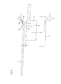
- FIG. 1 a curtain applicator 1 for coating a running paper, cardboard or other fibrous web 2 with a liquid to pasty application medium M shown. It includes, in addition to some other units not shown here, such as start / stop gutters, air boundary layer control equipment, Measuring devices, feed lines, etc. one above the fibrous web 2 and spaced therefrom arranged curtain application head. 3
- This application head 3 is provided with a slot nozzle directed toward the substrate to be coated or the continuous fibrous web.
- the device is marketed by the applicant's company as DF Coater (Direct Fountain Coater) and is also machine-wide.
- the application head 3 has a topicsmediumsverteilhunt 4 with feed gap, which merges into a slot-shaped outlet opening 5 with a trailing edge 6 and from which the application medium M in the form of a falling curtain 7 on the running in the direction of arrow L fibrous web 2 passes.
- the curtain 7 sets as a coating layer AS.
- the curtain applicator unit 1 at least one located below the edge 2a of the fibrous web 2 collecting channel 8 for collecting on the edge 2a of the fibrous web 2 exiting or squirting application medium M or parts thereof.
- the leaking or ejecting media parts of the fibrous web 2 and / or the fibrous web leading rollers 9 and 10 or other components not shown here pollute, one of the gutter 8 associated, also arranged below the fibrous web 2 collecting plate 11 is provided.
- This collecting plate 11 is rectangular and hollow in the example. In the cavity, it is filled with a cooling fluid. Thus, a cooling of the same is achieved, which forms on the surface of the collecting plate 11 condensate. This has the consequence that the collected order medium or color splashes MS do not dry there, but slip down into the gutter located underneath 8. There they are collected and withdrawn.
- the collecting plate 11 is preferably arranged at an angle ⁇ between 5 ° and 40 ° with respect to the fibrous web 2.
- This cooled collecting plate 11 is assigned in the example a tuyere 12, which directs the excess application medium parts or casters or paint mist MS to the collecting plate 11.
- the tuyere 12 is located above the edge 2a of the fibrous web 2 with an outflow direction on the region 2a of the fibrous web, up to said collecting plate 11.
- the tuyere is pressurized with compressed air and emits a blowing jet 12b.
- the blowing zone which widened with increasing distance, is shown in dashed lines.
- the outlet opening of the blowing nozzle 12 is designed as a flat jet nozzle, so that the blowing jet 12b generates a flattened cross-section.
- FIG. 1 It can be seen clearly that the collecting plate 11 is located above its associated collecting channel 8, wherein the collecting plate 11 with its top 11a to the fibrous web 2 has a distance a of about 5 mm and protrudes with its bottom 11 b in the gutter 8.
- the collecting plate 11 is arranged at a distance b in the downstream direction L of the fibrous web 2 after the curtain 7.
- the distance b extends from the extended line of the trailing edge 6 of the outlet opening 5 of the applicator head 3 to the front wall 11a of the erected collecting plate 11. This distance b is here about 70mm mm.
- blowing nozzle 12 is set against the fibrous web 2 in such a way that its blowing jet 12b acts down to the rear side 11d of the collecting plate 11 facing away from the curtain 7.
- the collecting plate 11 and the tuyere should be located under an existing start / stop channel 17.
- FIG. 2 is intended to show a possible embodiment in which the tuyere 12 is attached via a holder 13 to the collecting plate 11 and thereby jointly and expandable or at their distance b is adjustable to the curtain, as indicated by the double arrow.
- the holder has an incision or notch 13a for the fibrous web 2.
- This embodiment is a simple retrofitted catcher 14, which is easily installed in existing production machines or coaters nightly.
- the tuyere 12 has, moreover, in the FIG. 2 not visible slit-shaped outlet opening 12a, whereby one generates a sharply demarcated flat jet, which in turn generates a clean spatter-free edge 2a on the fibrous web 2.
- FIG. 2 Indicated in FIG. 2 is with arrows and the supply of the cooling fluid 15 for the collecting plate 11 and the supply of the blowing air 16 in the tuyere 12th
- FIG. 3 the lower part of the curtain applicator 1 is shown more clearly, wherein the web running direction is perpendicular to the image plane.
- the collecting plate 11 which is arranged at a distance from the fibrous web, for the most part projects even beyond the lateral edge 2a of the web.
- the blown with the nozzle 12 by Blasstrahl 12b medium generates a spatter-free edge, which is indicated in dashed lines.
- the collected at the edge of the medium from the gutter 8 is withdrawn via a drain 18, as shown by arrows.
- the collected medium can be disposed of or alternatively fed back to the media preparation.
Landscapes
- Paper (AREA)
- Coating Apparatus (AREA)
Abstract
Description
- Die Erfindung betrifft ein Vorhangauftragswerk zur Beschichtung einer durch eine Maschine zur Herstellung und/oder Veredelung sich bewegenden Papier-, Karton-oder anderen Faserstoffbahn mit wenigstens einem flüssigen bis pastösen Auftragsmedium, aufweisend einen oberhalb der Faserstoffbahn angeordneten maschinenbreiten Vorhang-Auftragskopf mit einer Auftragsmedium-Verteilkammer und einer Austrittsöffnung zur Abgabe des wenigstens einen Auftragsmediums in Form eines ein- oder mehrschichtigen, im Wesentlichen der Schwerkraft folgend auf die Faserstoffbahn herabfallenden Vorhangs sowie aufweisend wenigstens eine zumindest unterhalb des Randes der Faserstoffbahn befindliche Auffangrinne zum Auffangen von über den Rand der Faserstoffbahn austretendes Auftragsmedium bzw. Teilen (MS) davon.
- Eine gattungsgemäßes Vorhangauftragswerk (Curtain Coater) ist beispielsweise aus der
DE- A1 10012344 für einschichtigen Auftrag oder derDE- A1 103 59 117 für mehrschichtigen Auftrag bekannt. Bei diesen Auftragswerken weisen die Auftragsköpfe Schlitzdüsen auf, die nach unten in Richtung auf die zu beschichtende Faserstoffbahn zeigen und aus denen der Vorhang vorwiegend unter Einfluss der Schwerkraft herabfällt. Neben Auffangrinnen oder Wannen zum Auffangen von Auftragsmedium, welches über den Bahnrand fällt sind auch Auffangeinrichtungen für den Anfahrvorgang und das Beenden der Beschichtungsvorgangs, sowie Luftgrenzschicht-Bekämpfungseinrichtungen vorhanden. Aus derEP- A1- 1 255 615 ist eine andere Ausführungsart des Vorhangauftragswerks bekannt, welches in Fachkreisen als "Slide Die", also Gleitschicht- oder auch Kaskadendüse bezeichnet wird. Dieses Auftragswerk enthält mindestens zwei Auftragsmediumskammern, aus denen das Medium jeweils über einen Zufuhrspalt, der wiederum jeweils in eine schlitzförmige Austrittsöffnung übergeht, auf eine Gleitfläche der Düse gelangt. Das aus den parallel hintereinander angeordneten Austrittsöffnungen austretende Auftragsmedium legt sich dabei übereinander. An einer Abrisskante oder auch als Ablöselinie zu bezeichnenden Kante der Düse löst sich diese Mehrfachschicht ab und fällt als mehrschichtiger Vorhang herab entweder zunächst auf eine zwischengeschaltete Leitplatte oder direkt auf das zu beschichtende Substrat bzw. die Oberfläche der laufenden Faserstoffbahn. - Die vorstehend genannten Auffang- und Luftgrenzschicht-Bekämpfungseinrichtungen sind auch hier vorhanden.
- Beim Streichen - sowohl beim einschichtigen als auch mehrschichtigen Auftrag - mit dem Vorhangauftragswerk (Curtain Coater) kann die Beschichtungsbreite gleich oder auch kleiner als die Breite der Faserstoffbahn sein, was als Inboard-Fahrweise bezeichnet wird.
- Bei so genannter Overboard-Fahrweise ist dagegen die Vorhangbreite größer als die Faserstoffbahnbreite. Insbesondere bei dieser Fahrweise und vor allem bei den heute gefahrenen hohen Maschinengeschwindigkeiten, die größer als 1000m/min sind, kann es aufgrund von Randabspritzungen zu Verschmutzungen der Faserstoffbahn mit sehr großer Beeinträchtigung der Auftragsqualität und auch zu Verschmutzungen der die Faserstoffbahn führenden Bauteile komme, die ihrerseits die laufende Faserstoffbahn beeinträchtigen und deshalb in kurzen Intervallen aufwändig gereinigt werden müssen. Außerdem kommt es zu Farbüberhöhungen. Allgemein beträgt die Dicke der mit Vorhang aufgetragenen Strichschichten zwischen 5 und 50 Mikrometer. Es kann zu Randverdickungen führen, die eine Höhe bis zu 100 Mikrometer oder höher erreichen. Diese örtlichen Ungleichmäßigkeiten führen zu verschiedenen weiteren Problemen, wie:
- Beschädigung der Walzen von nachfolgenden Kalandern,
- ungleichmäßige Ränder und dadurch Ungleichmäßigkeit an der aufgewickelten Faserstoffbahnrolle
- starke Verschmutzung von nachfolgenden Leitwalzen, weil sich die Verdickungen nicht wegtrocknen lassen.
- Es ist daher Aufgabe der Erfindung, ein Vorhangauftragswerk anzugeben, bei dem die Nachteile des Standes der Technik nicht auftreten.
- Die Aufgabe der Erfindung wird mit einem Vorhang-Auftragswerk mit den Merkmalen des Anspruchs 1 gelöst. Erfindungsgemäß ist vorgesehen, dass jeder Auffangrinne eine Auffangplatte zugeordnet ist, wobei die Auffangplatte mit einem Kühlfluid beaufschlagt ist. Das Kühlfluid ist kälter als die Umgebungstemperatur, damit es die Oberflächentemperatur der Auffangplatte unterhalb der Temperatur der Umgebung hält. Bevorzugt sollte das Kühlmedium durch die Auffangplatte strömen.
- Aufgrund dieser Ausbildung ist es möglich, dass sich die hinausfallenden bzw. in unerwünschter Weise abspritzenden Auftragsmediumsteile zuerst an der gekühlten Auffangplatte anlegen und von da aus in die Auffangrinne gelangen. Durch die Kühlung bildet sich auf der Oberfläche der Auffangplatte Kondensationsflüssigkeit, so dass die Auftragsmediums- bzw. die Farbspritzer dort nicht antrocknen. Von den im Wesentlichen senkrecht oder auch schräg stehenden Wänden der Auffangplatte rutschen die Spritzer ab und fallen in die darunter befindliche Auffangrinne. Hier werden diese gesammelt und werden in einfacher Weise abgezogen.
- Zur Kühlung der Auffangplatte ist diese vorzugsweise hohl ausgebildet und mit dem Kühlfluid, beispielsweise Wasser, Öl, Alkohol oder speziellen Mischungen befüllt. Denkbar sind auch in die Auffangplatte eingearbeitete Kühlkanäle, durch die das gewählte Kühlfluid fließt.
- Gewünschtenfalls kann auch die Auffangwanne gekühlt sein.
- Eine zweckmäßige Ausbildung des Auftragswerks besteht darin, dass die Auffangplatte mit ihrer Oberseite zur Faserstoffbahn einen Spalt bzw. Abstand von 0 bis 20mm, vorzugsweise 3 bis 5 mm aufweist. Mit ihrer Unterseite ragt dagegen die Auffangplatte in die Auffangrinne zumindest teilweise hinein. Der genannte Spalt bzw. Abstand ist zwar wünschenswert, damit die schnelllaufende Faserstoffbahn (das sind Geschwindigkeiten von größer als ca. 1500 m/min) die Auffangplatte nicht tangieren kann und dadurch auch nicht beschädigt wird oder gar abreißt. Bei langsamer laufenden oder auch schmalen Bahnen kann ein Abstand von 0 mm, also ein direkter Kontakt zur Faserstoffbahn hingenommen werden.
- Durch diesen schmalen Spalt fliegen die Abspritzungen bzw. Farbnebel. Deshalb ist es zweckmäßig, wenn eine Blasdüse noch angeordnet ist, die mit einem Druckfluid, wie Druckluft oder einer Flüssigkeit beaufschlagbar ist. Mit der Blasdüse werden diese Partikel nach unten in die Auffangrinne überwiegend berührungslos geleitet, weshalb sie nicht weiter umherfliegen und Verunreinigungen oder Qualitätsbeeinträchtigungen in der Auftragsschicht hervorrufen können.
- Es soll an dieser Stelle gesagt sein, dass die Auffangrinne einen beliebigen Querschnitt aufweisen kann, der beispielsweise kegelförmig ausgebildet oder auch wannenartig erweitert sein kann. Der Begriff Auffangrinne ist nicht einschränkend anzusehen, sondern steht für beliebige Querschnittsformen. Auch diese Auffangrinne kann wie die Auffangplatte mit einem Kühlfluid beaufschlagt sein.
- Die Auffangrinne kann als separates Bauteil angeordnet sein. Einfacher auswechselbar bzw. ein- und ausbaubar ist aber eine Bauform, bei der die Auffangplatte integraler Bestandteil der ihr zugeordneten Auffangrinne ist. Die Auffangplatte ist nicht maschinenbreit ausgeführt und befindet sich nur an mindestens einem Rand der Auftragszone, wohingegen die Auffangrinne auch maschinenbreit sein kann.
- Im Zusammenhang mit dem besagten Abstand der Auffangplatte zur Faserstoffbahn ist anzumerken, dass das oben angegebene kleinere Maß zu wählen ist, wenn keine Blasdüse vorhanden ist.
- Ferner ist vorgesehen, dass die Auffangplatte in stromabwärtiger Richtung dem Vorhang-Auftragskopf bzw. einer Auftrefflinie des Vorhanges auf der Faserstoffbahn in einem Abstand zwischen 40 und 100.mm nachgeordnet ist.
- Dieser Abstand sollte allerdings nicht größer als 500 mm sein, weil sich sonst die Spritzer bzw. Partikel des Auftragsmediums an unerwünschten Stellen doch anlegen und antrocknen.
- Außerdem ist es vorteilhaft, wenn die Auffangplatte zur Faserstoffbahn einen Winkel zwischen 5° und 90°, bevorzugt aber 5° und 40° aufweist. Durch die Schrägstellung können die aufzufangenden Mediumsteile besser von der Auffangfläche aufgenommen werden.
- Nachzutragen ist, dass die Blasdüse bevorzugt eine schlitzartig ausgebildete Austrittsöffnung aufweist und damit einen Flachstrahl erzeugt. Damit bildet sich zur ein relativ scharf begrenzter Blasstrahls, der auf den Rand der Faserstoffbahn gerichtet ist, wodurch Spritzer und Farbnebel vom Vorhangrand in Richtung der Auffangrinne abgeführt werden.
- Im Übrigen ist vorgesehen, dass die Blasdüse derart gegen die Faserstoffbahn angestellt ist, dass deren Blasstrahl auch auf die vom Vorhang abgewandte Rückseite der Auffangplatte wirkt.
- Damit wird erreicht, dass der abgegeben Vorhang unbeeinträchtigt vom Blasstrahl fallen kann, also weder einreißt noch sich einschnürt. Die aus dem Stand der Technik bekannten Einrichtungen zum Führen der Ränder des Vorhangs und auch die vor dem Vorhang angeordneten Luftgrenzschicht-Bekämpfungseinrichtungen sind selbstverständlich auch beim erfindungsgemäßen Vorhangauftragswerk anwendbar.
- Vorteilhaft ist es, wenn die Auffangplatte und die Blasdüse unter einer vorhandenen Start-/Stopp-Rinne angeordnet sind. Damit lassen sich Verschmutzungen der Blasdüse und der gekühlten Auffangplatte beim Start oder Unterbrechungen des Streichvorgangs vermeiden.
- Die Erfindung betrifft auch eine Auffangeinrichtung für abgeschleudertes bzw. abgespritztes Auftragsmedium während der Beschichtung einer sich durch eine Maschine zur Herstellung und/oder Veredelung bewegenden Papier-, Karton- oder anderen Faserstoffbahn, die gekennzeichnet ist durch die gemäß Anspruch 1 bis 12 angegebenen Merkmale
- Diese Auffangeinrichtung lässt sich problemlos in bestehende Streichmaschinen einbauen. Vorzugsweise ist die Auffangeinrichtung geeignet für neu konzipierte, aber auch bereits bestehende Vorhangauftragswerke.
- Die Auffangeinrichtung kann sowohl einer Randseite zugeordnet sein, als auch an beiden Bahnrändern, also führer- und triebseitig. Die beidseitige Anordnung ist bevorzugt, weil die Abspritzungen des Auftragsmediums bzw. Farbnebel gleichermaßen zu beiden Seiten der heute oftmals mit mehr als 1500m/min schnell durch die Herstellungs- oder Veredelungsmaschine laufenden Faserstoffbahn auftreten und deshalb dort auch aufgefangen werden sollen.
- Nachfolgend wird die Erfindung anhand eines Ausführungsbeispieles näher erläutert. Es zeigen in schematischer Darstellung:
- Figur 1:
- ein erfindungsgemäßes in der Seitenansicht schematisch dargestelltes Vorhang-Auftragwerk;
- Figur 2:
- das erfindungsgemäße Vorhangauftragswerk gemäß
Figur 1 in schematischer, perspektivischer Darstellung; - Figur 3:
- das erfindungsgemäße Vorhangauftragswerk gemäß
Figur 1 in Maschinenlängsrichtung dargestellt; - Es ist anzumerken, dass in den Beispielen gemäß den
Figuren 1 bis 3 nur ein einschichtiger Auftrag dargestellt ist. Es könnte aber auch ein mehrschichtiger Vorhang abgegeben bzw. eine Mehrfach-Auftragsschicht erzeugt werden. - In den Figuren sind gleiche Bauteile bzw. Bezeichnungen mit gleichen Bezugszeichen versehen.
- In den
Figuren 2 und3 ist nur eine Hälfte der Breite des Auftragswerkes und auch der Faserstoffbahn dargestellt, die zweite Hälfte ist identisch ausgebildet. - In der
Figur 1 ist ein Vorhangauftragswerk 1 zur Beschichtung einer laufenden Papier-, Karton- oder anderen Faserstoffbahn 2 mit einem flüssigen bis pastösen Auftragsmedium M gezeigt. Es umfasst neben einigen anderen hier nicht mit dargestellten Einheiten, wie Start/Stopp-Auffangrinnen, Luftgrenzschicht-Bekämpfungseinrichtungen, Messeinrichtungen, Zuführleitungen usw. einen oberhalb der Faserstoffbahn 2 und von ihr beabstandet angeordneten Vorhang-Auftragskopf 3. - Dieser Auftragskopf 3 mit einer zum zu beschichtenden Substrat bzw. der laufenden Faserstoffbahn gerichteten Schlitzdüse versehen. Die Vorrichtung wird vom Unternehmen der Anmelderin als DF-Coater (Direct Fountain Coater) vertrieben und ist überdies maschinenbreit ausgeführt ist. Der Auftragskopf 3 weist eine Auftragsmediumsverteilkammer 4 mit Zufuhrspalt auf, der in eine schlitzförmige Austrittsöffnung 5 mit einer Abrisskante 6 übergeht und von der aus das Auftragsmedium M in Form eines fallenden Vorhangs 7 auf die in Pfeilrichtung L laufende Faserstoffbahn 2 gelangt.
- Auf der Oberfläche der Faserstoffbahn 2 legt sich der Vorhang 7 als Auftragsschicht AS ab.
- Wie aus
Figur 1 zu entnehmen ist, weist das Vorhangauftragswerk 1 wenigstens eine unterhalb des Randes 2a der Faserstoffbahn 2 befindliche Auffangrinne 8 zum Auffangen von über den Rand 2a der Faserstoffbahn 2 austretendes oder abspritzendes Auftragsmedium M bzw. Teilen davon auf. - Damit die austretenden bzw. abspritzenden Mediumsteile die Faserstoffbahn 2 und/oder die die Faserstoffbahn führenden Walzen 9 und 10 oder weitere hier nicht dargestellte Bauteile nicht verschmutzen, ist eine der Auffangrinne 8 zugeordnete, ebenfalls unterhalb der Faserstoffbahn 2 angeordnete Auffangplatte 11 vorgesehen. Diese Auffangplatte 11 ist im Beispiel rechteckförmig und hohl ausgebildet. Im Hohlraum ist sie mit einem Kühlfluid befüllt. Damit wird eine Kühlung derselben erreicht, wodurch sich auf der Oberfläche der Auffangplatte 11 Kondenswasser bildet. Das hat zur Folge, dass die aufgefangenen Auftragsmediums- bzw. Farbspritzer MS dort nicht antrocknen, aber dafür nach unten in die darunter befindliche Auffangrinne 8 rutschen. Dort werden sie gesammelt und abgezogen. Die Auffangplatte 11 ist im Übrigen zur Faserstoffbahn 2 bevorzugt in einem Winkel α zwischen 5° und 40° angeordnet.
- Dieser gekühlten Auffangplatte 11 ist im Beispiel eine Blasdüse 12 zugeordnet, die die überschüssigen Auftragsmediumsteile bzw. Abspritzer oder Farbnebel MS zur Auffangplatte 11 leitet. Die Blasdüse 12 befindet sich oberhalb des Randes 2a der Faserstoffbahn 2 mit einer Ausströmrichtung auf Bereich des Randes 2a der Faserstoffbahn, bis hin zur besagten Auffangplatte 11. Die Blasdüse ist mit Druckluft beaufschlagt und gibt einen Blasstrahl 12b ab. Die Blaszone, die sich mit größer werdenden Abstand verbreitert, ist gestrichelt eingezeichnet. Die Austrittsöffnung der Blasdüse 12 ist als Flachstrahldüse ausgeführt, so dass der Blasstrahl 12b einen abgeflachten Querschnitt erzeugt.
- In
Figur 1 sieht man deutlich, dass die Auffangplatte 11 sich über der ihr zugeordneten Auffangrinne 8 befindet, wobei die Auffangplatte 11 mit ihrer Oberseite 11a zur Faserstoffbahn 2 einen Abstand a von ca. 5 mm aufweist und mit ihrer Unterseite 11 b in die Auffangrinne 8 hineinragt. - Die Auffangplatte 11 ist in einem Abstand b in stromabwärtiger Richtung L der Faserstoffbahn 2 nach dem Vorhang 7 angeordnet. Der Abstand b reicht von der verlängerten Linie der Abrisskante 6 der Austrittsöffnung 5 des Auftragskopfes 3 bis zur Vorderwand 11a der aufgestellten Auffangplatte 11. Dieser Abstand b beträgt hier ca. 70mm mm.
- In der
Figur 1 sieht man auch, dass die Blasdüse 12 derart gegen die Faserstoffbahn 2 angestellt ist, dass deren Blasstrahl 12b bis auf die vom Vorhang 7 abgewandte Rückseite 11d der Auffangplatte 11 hin wirkt. - Um Verschmutzungen der Blasdüse 12 und der gekühlten Auffangplatte 11 beim Start oder beim unterbrechen des Streichvorgangs zu vermeiden, sollte die Auffangplatte 11 und die Blasdüse unter einer vorhandenen Start-/Stopp-Rinne 17 angeordnet sein.
-
Figur 2 soll eine mögliche Ausführungsform zeigen, bei der die Blasdüse 12 über eine Halterung 13 mit der Auffangplatte 11 befestigt ist und dadurch gemeinsam ein-und ausbaubar oder auch in ihrem Abstand b zum Vorhang verstellbar ist, wie der Doppelpfeil angibt. Die Halterung weist einen Einschnitt bzw. Einkerbung 13a für die Faserstoffbahn 2 auf. - Diese Ausführung stellt eine einfach nachzurüstende Auffangeinrichtung 14 dar, die nachtäglich problemlos in bestehende Herstellungsmaschinen oder Streichmaschinen einbaubar ist.
- Die Blasdüse 12 hat im Übrigen eine in der
Figur 2 nicht sichtbare schlitzförmig Austrittsöffnung 12a, wodurch man einen scharf abgegrenzten Flachstrahl erzeugt, der wiederum einen sauberen spritzerfreien Rand 2a auf der Faserstoffbahn 2 erzeugt. - Angedeutet in
Figur 2 ist mit Pfeilen auch die Zuführung des Kühlfluids 15 für die Auffangplatte 11 sowie die Zuführung der Blasluft 16 in die Blasdüse 12. - In
Figur 3 ist der untere Teil des Vorhangauftragswerks 1 deutlicher dargestellt, wobei die Bahnlaufrichtung senkrecht zur Bildebene verläuft. Man erkennt, dass die im Abstand a zur Faserstoffbahn angeordnete Auffangplatte 11 zum überwiegenden Teil sogar über den seitlichen Rand 2a der Bahn hinausragt. Das mit der Blasdüse 12 mittels Blasstrahl 12b abgeblasenen Mediums erzeugt einen spritzerfreien Rand, der in gestrichelten Linien angegeben ist. Außerdem erkennt man, dass das am Rand aufgefangene Medium aus der Auffangrinne 8 über einen Ablauf 18 abgezogen wird, wie mit Pfeilen dargestellt ist. Das aufgefangene Medium kann entsorgt werden oder alternativ der Medienaufbereitung wieder zugeführt werden. -
- 1
- Vorhangauftragswerk
- 2
- Faserstoffbahn
- 2a
- Rand der Faserstoffbahn
- 3
- Auftragskopf
- 4
- Auftragsmediumsverteilkammer
- 5
- Austrittsöffnung
- 6
- Abrisskante
- 7
- Vorhang
- 8
- Auffangrinne
- 9
- Walze
- 10
- Walze
- 11
- Auffangplatte
- 11a
- Oberseite
- 11b
- Unterseite
- 11c
- Vorderseite
- 11d
- Rückseite
- 12
- Blasdüse
- 12a
- Austrittsöffnung
- 12b
- Blasstrahl
- 13
- Halterung
- 13a
- Einkerbung
- 14
- Auffangeinrichtung
- 15
- Kühlfluid
- 16
- Blasluft
- 17
- Startrinne
- 18
- Ablauf
- α
- Winkel
- a
- Spalt bzw. Abstand
- b
- Abstand
- AS
- Auftragsschicht
- L
- Bewegungs- bzw. Laufrichtung
- M
- Auftragsmedium
- MS
- Mediumsteil
Claims (14)
- Vorhangauftragswerk (1) zur Beschichtung einer durch eine Maschine zur Herstellung und/oder Veredelung sich bewegenden Papier-, Karton- oder anderen Faserstoffbahn (2) mit wenigstens einem flüssigen bis pastösen Auftragsmedium (M), aufweisend einen oberhalb der Faserstoffbahn (2) angeordneten maschinenbreiten Vorhang-Auftragskopf (3) mit einer Auftragsmedium- Verteilkammer (4) und einer Austrittsöffnung (5) zur Abgabe des wenigstens einen Auftragsmediums in Form eines ein- oder mehrschichtigen, im Wesentlichen der Schwerkraft folgend auf die Faserstoffbahn (2) herabfallenden Vorhangs (7) sowie aufweisend wenigstens eine zumindest unterhalb des Randes (2a) der Faserstoffbahn (2) befindliche Auffangrinne (8) zum Auffangen von über den Rand (2a) der Faserstoffbahn (2) austretendes Auftragsmedium bzw. Teilen (MS) davon,
dadurch gekennzeichnet, dass
der Auffangrinne (8) eine sich ebenfalls unterhalb der Faserstoffbahn (2) befindliche Auffangplatte (11) zugeordnet ist, wobei die Auffangplatte (11) mit einem Kühlfluid (15) beaufschlagt ist. - Vorhangauftragswerk nach Anspruch 1,
dadurch gekennzeichnet, dass
die Auffangplatte (11) sich im Wesentlichen nur unterhalb des Randes (2a) der Faserstoffbahn (2) befindet. - Vorhangauftragswerk nach Anspruch 1 oder 2,
dadurch gekennzeichnet, dass
die Auffangplatte (11) hohl ausgebildet ist und mit dem Kühlfluid (15) befüllt ist. - Vorhangauftragswerk nach Anspruch 1 oder 2,
dadurch gekennzeichnet, dass
die Auffangplatte (11) Kanäle enthält, durch die das Kühlfluid (15) strömt. - Vorhangauftragswerk nach wenigstens einem der vorangehenden Ansprüche, dadurch gekennzeichnet, dass
die Auffangplatte (11) als separates Bauteil angeordnet ist oder integraler Bestandteil der Auffangrinne (8) ist. - Vorhangauftragswerk nach wenigstens einem der vorangehenden Ansprüche, dadurch gekennzeichnet, dass
der Auffangplatte (11) eine Blasdüse (12) zugeordnet ist, die mit einem Druckfluid beaufschlagbar ist und in Richtung auf die Auffangplatte (11) bläst. - Vorhangauftragswerk nach wenigstens einem der vorangehenden Ansprüche, dadurch gekennzeichnet, dass
die Auffangplatte (11) sich oberhalb der ihr zugeordneten Auffangrinne (8) befindet, wobei die Auffangplatte (11) mit ihrer Oberseite (11a) zur Faserstoffbahn (2) einen Spalt bzw. Abstand (a) von 0 bis 20mm, vorzugsweise 3 bis 5 mm aufweist und mit ihrer Unterseite (11 b) in die Auffangrinne (8) zumindest teilweise hineinragt. - Vorhangauftragswerk nach wenigstens einem der vorangehenden Ansprüche, dadurch gekennzeichnet, dass
die Auffangplatte (11) in einem Abstand (b) in stromabwärtiger Richtung der Faserstoffbahn (2) dem Vorhang (7) bzw. einer Vorhang-Abrisskante (6) an der Austrittsöffnung (5) des Auftragskopfes (3) nachgeordnet ist. - Vorhangauftragswerk nach Anspruch 8,
dadurch gekennzeichnet, dass
der Abstand (b) ca. 40 bis 100 mm beträgt. - Vorhangauftragswerk nach wenigstens einem der vorherigen Ansprüche, dadurch gekennzeichnet, dass
die Blasdüse (12) einen vorzugsweise schlitzförmigen Ausströmquerschnitt aufweist und damit einen Blasstrahl (12b) mit abgeflachtem Querschnitt erzeugt. - Vorhangauftragswerk nach Anspruch 10,
dadurch gekennzeichnet, dass
die Blasdüse (12) derart gegen die Faserstoffbahn (2) angestellt ist, dass deren Blasstrahl (12b) bis auf die vom Vorhang (7) abgewandte Rückseite (11d) der Auffangplatte (11) wirkt. - Vorhangauftragswerk nach wenigstens einem der vorherigen Ansprüche,
dadurch gekennzeichnet, dass
die Auffangplatte (11) und die Blasdüse (12) unter einer vorhandenen Start-/Stopp-Rinne (17) angeordnet sind. - Vorhangauftragswerk nach wenigstens einem der vorherigen Ansprüche,
dadurch gekennzeichnet, dass
die Auffangplatte 11 zur Faserstoffbahn 2 in einem Winkel α zwischen 5° und 90°, vorzugsweise 5° bis 40° angeordnet ist. - Auffangeinrichtung (14) für vom Rand des Vorhangs (7) abgeschleudertes bzw. abgespritztes Auftragsmedium (MS) während der Beschichtung einer sich durch eine Maschine zur Herstellung und/oder Veredelung bewegenden Papier-, Karton- oder anderen Faserstoffbahn (2),
gekennzeichnet durch die gemäß Anspruch 1 bis 13 angegebenen Merkmale.
Applications Claiming Priority (1)
| Application Number | Priority Date | Filing Date | Title |
|---|---|---|---|
| DE201010031556 DE102010031556A1 (de) | 2010-07-20 | 2010-07-20 | Vorhangauftragswerk |
Publications (2)
| Publication Number | Publication Date |
|---|---|
| EP2409781A1 true EP2409781A1 (de) | 2012-01-25 |
| EP2409781B1 EP2409781B1 (de) | 2014-10-15 |
Family
ID=44764277
Family Applications (1)
| Application Number | Title | Priority Date | Filing Date |
|---|---|---|---|
| EP20110173624 Not-in-force EP2409781B1 (de) | 2010-07-20 | 2011-07-12 | Vorhangauftragswerk |
Country Status (2)
| Country | Link |
|---|---|
| EP (1) | EP2409781B1 (de) |
| DE (1) | DE102010031556A1 (de) |
Cited By (1)
| Publication number | Priority date | Publication date | Assignee | Title |
|---|---|---|---|---|
| CN102744182A (zh) * | 2012-07-18 | 2012-10-24 | 盐城宏亚机械有限公司 | 复合机上胶机构 |
Citations (5)
| Publication number | Priority date | Publication date | Assignee | Title |
|---|---|---|---|---|
| DE10012344A1 (de) | 2000-03-14 | 2001-09-20 | Voith Paper Patent Gmbh | Vorhang-Auftragsverfahren |
| EP1255615A1 (de) | 2000-01-26 | 2002-11-13 | Tetra Laval Holdings & Finance S.A. | Verfahren zur herstellung eines viellagen-verpackungslaminats und entsprechend hergestelltes verpackungslaminat |
| DE10359117A1 (de) | 2003-12-17 | 2005-07-28 | Voith Paper Patent Gmbh | Vorhangauftragswerk |
| DE102008040404A1 (de) * | 2008-07-15 | 2010-01-21 | Voith Patent Gmbh | Vorhang-Auftragswerk |
| DE102008046411A1 (de) * | 2008-09-04 | 2010-03-11 | Eisenmann Anlagenbau Gmbh & Co. Kg | Vorrichtung zum Abscheiden von Lack-Overspray |
-
2010
- 2010-07-20 DE DE201010031556 patent/DE102010031556A1/de not_active Withdrawn
-
2011
- 2011-07-12 EP EP20110173624 patent/EP2409781B1/de not_active Not-in-force
Patent Citations (5)
| Publication number | Priority date | Publication date | Assignee | Title |
|---|---|---|---|---|
| EP1255615A1 (de) | 2000-01-26 | 2002-11-13 | Tetra Laval Holdings & Finance S.A. | Verfahren zur herstellung eines viellagen-verpackungslaminats und entsprechend hergestelltes verpackungslaminat |
| DE10012344A1 (de) | 2000-03-14 | 2001-09-20 | Voith Paper Patent Gmbh | Vorhang-Auftragsverfahren |
| DE10359117A1 (de) | 2003-12-17 | 2005-07-28 | Voith Paper Patent Gmbh | Vorhangauftragswerk |
| DE102008040404A1 (de) * | 2008-07-15 | 2010-01-21 | Voith Patent Gmbh | Vorhang-Auftragswerk |
| DE102008046411A1 (de) * | 2008-09-04 | 2010-03-11 | Eisenmann Anlagenbau Gmbh & Co. Kg | Vorrichtung zum Abscheiden von Lack-Overspray |
Cited By (1)
| Publication number | Priority date | Publication date | Assignee | Title |
|---|---|---|---|---|
| CN102744182A (zh) * | 2012-07-18 | 2012-10-24 | 盐城宏亚机械有限公司 | 复合机上胶机构 |
Also Published As
| Publication number | Publication date |
|---|---|
| EP2409781B1 (de) | 2014-10-15 |
| DE102010031556A1 (de) | 2012-01-26 |
Similar Documents
| Publication | Publication Date | Title |
|---|---|---|
| DE60105477T2 (de) | Beschichtungs-Vorrichtung und Verfahren | |
| EP1861207B1 (de) | Auftragsvorrichtung | |
| DE102008021541B4 (de) | Verfahren und Vorrichtung zum Behandeln einer Faserbahn | |
| DE102022105518B4 (de) | Auftragsdüse, Auftragswerk und Verfahren | |
| EP0977920A1 (de) | Verfahren und vorrichtung zum auftragen einer pigmentstreichfarbe auf eine papier- oder kartonbahn | |
| DE10012344A1 (de) | Vorhang-Auftragsverfahren | |
| EP2146003A2 (de) | Vorhang-Auftragswerk | |
| EP1003934B1 (de) | Verfahren und vorrichtung zum auftragen einer pigmentstreichfarbe auf eine papier- oder kartonbahn | |
| DE202017100655U1 (de) | Vorrichtung zur Behandlung von Faserbahnen | |
| DE10232949A1 (de) | Vorhang-Auftragsvorrichtung | |
| DE19702605A1 (de) | Vorrichtung und Verfahren zum direkten oder indirekten Auftragen eines flüssigen oder pastösen Mediums auf eine laufende Materialbahn | |
| EP2622137A1 (de) | Vorrichtung zum direkten oder indirekten auftrag von flüssigem bis pastösem auftragsmedium und verfahren zum betreiben einer derartigen vorrichtung | |
| EP2409781B1 (de) | Vorhangauftragswerk | |
| EP2396121A1 (de) | Vorhang-auftragswerk | |
| EP2379230A1 (de) | Vorhangauftragswerk | |
| EP1782891B1 (de) | Verfahren und Vorrichtung zum wenigstens zweischichtigen Auftrag von Streichfarbe auf die Oberfläche einer laufenden Bahn, insbesondere Papier- oder Kartonbahn | |
| EP1801289A1 (de) | Verfahren und Vorrichtung zum Auftragen eines Auftragsmediums auf eine Materialbahn | |
| EP2111925A1 (de) | Vorhang-Auftragswerk | |
| EP2070600B1 (de) | Verfahren zur Beschichtung einer laufenden Papier-, Karton- oder anderen Faserstoffbahn mittels Vorhangbeschichtung | |
| EP2198975A1 (de) | Vorhang-Auftragswerk | |
| EP2082811A2 (de) | Mehrfach-Vorhangstreichvorrichtung | |
| EP2017012A2 (de) | Vorhangstreichmaschine | |
| DE102008040405A1 (de) | Vorhang-Auftragswerk | |
| EP2067531A2 (de) | Randführung | |
| DE102005035317A1 (de) | Auftragsverfahren |
Legal Events
| Date | Code | Title | Description |
|---|---|---|---|
| AK | Designated contracting states |
Kind code of ref document: A1 Designated state(s): AL AT BE BG CH CY CZ DE DK EE ES FI FR GB GR HR HU IE IS IT LI LT LU LV MC MK MT NL NO PL PT RO RS SE SI SK SM TR |
|
| AX | Request for extension of the european patent |
Extension state: BA ME |
|
| PUAI | Public reference made under article 153(3) epc to a published international application that has entered the european phase |
Free format text: ORIGINAL CODE: 0009012 |
|
| RIN1 | Information on inventor provided before grant (corrected) |
Inventor name: MENDEZ-GALLON, BENJAMIN, DR. |
|
| 17P | Request for examination filed |
Effective date: 20120725 |
|
| RIC1 | Information provided on ipc code assigned before grant |
Ipc: B05C 11/10 20060101AFI20140213BHEP Ipc: D21H 23/48 20060101ALI20140213BHEP Ipc: B05D 1/30 20060101ALI20140213BHEP Ipc: B05C 9/06 20060101ALN20140213BHEP Ipc: B05C 5/00 20060101ALN20140213BHEP |
|
| GRAP | Despatch of communication of intention to grant a patent |
Free format text: ORIGINAL CODE: EPIDOSNIGR1 |
|
| INTG | Intention to grant announced |
Effective date: 20140509 |
|
| RIC1 | Information provided on ipc code assigned before grant |
Ipc: B05D 1/30 20060101ALI20140429BHEP Ipc: D21H 23/48 20060101ALI20140429BHEP Ipc: B05C 11/10 20060101AFI20140429BHEP Ipc: B05C 9/06 20060101ALN20140429BHEP Ipc: B05C 5/00 20060101ALN20140429BHEP |
|
| GRAS | Grant fee paid |
Free format text: ORIGINAL CODE: EPIDOSNIGR3 |
|
| GRAA | (expected) grant |
Free format text: ORIGINAL CODE: 0009210 |
|
| AK | Designated contracting states |
Kind code of ref document: B1 Designated state(s): AL AT BE BG CH CY CZ DE DK EE ES FI FR GB GR HR HU IE IS IT LI LT LU LV MC MK MT NL NO PL PT RO RS SE SI SK SM TR |
|
| REG | Reference to a national code |
Ref country code: CH Ref legal event code: EP Ref country code: GB Ref legal event code: FG4D Free format text: NOT ENGLISH |
|
| REG | Reference to a national code |
Ref country code: IE Ref legal event code: FG4D Free format text: LANGUAGE OF EP DOCUMENT: GERMAN |
|
| REG | Reference to a national code |
Ref country code: AT Ref legal event code: REF Ref document number: 691384 Country of ref document: AT Kind code of ref document: T Effective date: 20141115 |
|
| REG | Reference to a national code |
Ref country code: DE Ref legal event code: R096 Ref document number: 502011004668 Country of ref document: DE Effective date: 20141127 |
|
| REG | Reference to a national code |
Ref country code: NL Ref legal event code: VDEP Effective date: 20141015 |
|
| REG | Reference to a national code |
Ref country code: LT Ref legal event code: MG4D |
|
| PG25 | Lapsed in a contracting state [announced via postgrant information from national office to epo] |
Ref country code: NL Free format text: LAPSE BECAUSE OF FAILURE TO SUBMIT A TRANSLATION OF THE DESCRIPTION OR TO PAY THE FEE WITHIN THE PRESCRIBED TIME-LIMIT Effective date: 20141015 |
|
| PG25 | Lapsed in a contracting state [announced via postgrant information from national office to epo] |
Ref country code: LT Free format text: LAPSE BECAUSE OF FAILURE TO SUBMIT A TRANSLATION OF THE DESCRIPTION OR TO PAY THE FEE WITHIN THE PRESCRIBED TIME-LIMIT Effective date: 20141015 Ref country code: IS Free format text: LAPSE BECAUSE OF FAILURE TO SUBMIT A TRANSLATION OF THE DESCRIPTION OR TO PAY THE FEE WITHIN THE PRESCRIBED TIME-LIMIT Effective date: 20150215 Ref country code: ES Free format text: LAPSE BECAUSE OF FAILURE TO SUBMIT A TRANSLATION OF THE DESCRIPTION OR TO PAY THE FEE WITHIN THE PRESCRIBED TIME-LIMIT Effective date: 20141015 Ref country code: NO Free format text: LAPSE BECAUSE OF FAILURE TO SUBMIT A TRANSLATION OF THE DESCRIPTION OR TO PAY THE FEE WITHIN THE PRESCRIBED TIME-LIMIT Effective date: 20150115 Ref country code: PT Free format text: LAPSE BECAUSE OF FAILURE TO SUBMIT A TRANSLATION OF THE DESCRIPTION OR TO PAY THE FEE WITHIN THE PRESCRIBED TIME-LIMIT Effective date: 20150216 |
|
| PG25 | Lapsed in a contracting state [announced via postgrant information from national office to epo] |
Ref country code: RS Free format text: LAPSE BECAUSE OF FAILURE TO SUBMIT A TRANSLATION OF THE DESCRIPTION OR TO PAY THE FEE WITHIN THE PRESCRIBED TIME-LIMIT Effective date: 20141015 Ref country code: PL Free format text: LAPSE BECAUSE OF FAILURE TO SUBMIT A TRANSLATION OF THE DESCRIPTION OR TO PAY THE FEE WITHIN THE PRESCRIBED TIME-LIMIT Effective date: 20141015 Ref country code: HR Free format text: LAPSE BECAUSE OF FAILURE TO SUBMIT A TRANSLATION OF THE DESCRIPTION OR TO PAY THE FEE WITHIN THE PRESCRIBED TIME-LIMIT Effective date: 20141015 Ref country code: SE Free format text: LAPSE BECAUSE OF FAILURE TO SUBMIT A TRANSLATION OF THE DESCRIPTION OR TO PAY THE FEE WITHIN THE PRESCRIBED TIME-LIMIT Effective date: 20141015 Ref country code: CY Free format text: LAPSE BECAUSE OF FAILURE TO SUBMIT A TRANSLATION OF THE DESCRIPTION OR TO PAY THE FEE WITHIN THE PRESCRIBED TIME-LIMIT Effective date: 20141015 Ref country code: LV Free format text: LAPSE BECAUSE OF FAILURE TO SUBMIT A TRANSLATION OF THE DESCRIPTION OR TO PAY THE FEE WITHIN THE PRESCRIBED TIME-LIMIT Effective date: 20141015 Ref country code: GR Free format text: LAPSE BECAUSE OF FAILURE TO SUBMIT A TRANSLATION OF THE DESCRIPTION OR TO PAY THE FEE WITHIN THE PRESCRIBED TIME-LIMIT Effective date: 20150116 |
|
| REG | Reference to a national code |
Ref country code: DE Ref legal event code: R097 Ref document number: 502011004668 Country of ref document: DE |
|
| PG25 | Lapsed in a contracting state [announced via postgrant information from national office to epo] |
Ref country code: EE Free format text: LAPSE BECAUSE OF FAILURE TO SUBMIT A TRANSLATION OF THE DESCRIPTION OR TO PAY THE FEE WITHIN THE PRESCRIBED TIME-LIMIT Effective date: 20141015 Ref country code: CZ Free format text: LAPSE BECAUSE OF FAILURE TO SUBMIT A TRANSLATION OF THE DESCRIPTION OR TO PAY THE FEE WITHIN THE PRESCRIBED TIME-LIMIT Effective date: 20141015 Ref country code: DK Free format text: LAPSE BECAUSE OF FAILURE TO SUBMIT A TRANSLATION OF THE DESCRIPTION OR TO PAY THE FEE WITHIN THE PRESCRIBED TIME-LIMIT Effective date: 20141015 Ref country code: SK Free format text: LAPSE BECAUSE OF FAILURE TO SUBMIT A TRANSLATION OF THE DESCRIPTION OR TO PAY THE FEE WITHIN THE PRESCRIBED TIME-LIMIT Effective date: 20141015 Ref country code: RO Free format text: LAPSE BECAUSE OF FAILURE TO SUBMIT A TRANSLATION OF THE DESCRIPTION OR TO PAY THE FEE WITHIN THE PRESCRIBED TIME-LIMIT Effective date: 20141015 |
|
| PLBE | No opposition filed within time limit |
Free format text: ORIGINAL CODE: 0009261 |
|
| STAA | Information on the status of an ep patent application or granted ep patent |
Free format text: STATUS: NO OPPOSITION FILED WITHIN TIME LIMIT |
|
| PG25 | Lapsed in a contracting state [announced via postgrant information from national office to epo] |
Ref country code: IT Free format text: LAPSE BECAUSE OF FAILURE TO SUBMIT A TRANSLATION OF THE DESCRIPTION OR TO PAY THE FEE WITHIN THE PRESCRIBED TIME-LIMIT Effective date: 20141015 |
|
| 26N | No opposition filed |
Effective date: 20150716 |
|
| PG25 | Lapsed in a contracting state [announced via postgrant information from national office to epo] |
Ref country code: SI Free format text: LAPSE BECAUSE OF FAILURE TO SUBMIT A TRANSLATION OF THE DESCRIPTION OR TO PAY THE FEE WITHIN THE PRESCRIBED TIME-LIMIT Effective date: 20141015 Ref country code: MC Free format text: LAPSE BECAUSE OF FAILURE TO SUBMIT A TRANSLATION OF THE DESCRIPTION OR TO PAY THE FEE WITHIN THE PRESCRIBED TIME-LIMIT Effective date: 20141015 |
|
| REG | Reference to a national code |
Ref country code: CH Ref legal event code: PL |
|
| GBPC | Gb: european patent ceased through non-payment of renewal fee |
Effective date: 20150712 |
|
| PG25 | Lapsed in a contracting state [announced via postgrant information from national office to epo] |
Ref country code: LU Free format text: LAPSE BECAUSE OF FAILURE TO SUBMIT A TRANSLATION OF THE DESCRIPTION OR TO PAY THE FEE WITHIN THE PRESCRIBED TIME-LIMIT Effective date: 20150712 |
|
| REG | Reference to a national code |
Ref country code: IE Ref legal event code: MM4A |
|
| PG25 | Lapsed in a contracting state [announced via postgrant information from national office to epo] |
Ref country code: CH Free format text: LAPSE BECAUSE OF NON-PAYMENT OF DUE FEES Effective date: 20150731 Ref country code: LI Free format text: LAPSE BECAUSE OF NON-PAYMENT OF DUE FEES Effective date: 20150731 Ref country code: GB Free format text: LAPSE BECAUSE OF NON-PAYMENT OF DUE FEES Effective date: 20150712 |
|
| REG | Reference to a national code |
Ref country code: FR Ref legal event code: ST Effective date: 20160331 |
|
| PG25 | Lapsed in a contracting state [announced via postgrant information from national office to epo] |
Ref country code: FR Free format text: LAPSE BECAUSE OF NON-PAYMENT OF DUE FEES Effective date: 20150731 |
|
| PG25 | Lapsed in a contracting state [announced via postgrant information from national office to epo] |
Ref country code: IE Free format text: LAPSE BECAUSE OF NON-PAYMENT OF DUE FEES Effective date: 20150712 |
|
| PG25 | Lapsed in a contracting state [announced via postgrant information from national office to epo] |
Ref country code: MT Free format text: LAPSE BECAUSE OF FAILURE TO SUBMIT A TRANSLATION OF THE DESCRIPTION OR TO PAY THE FEE WITHIN THE PRESCRIBED TIME-LIMIT Effective date: 20141015 |
|
| PG25 | Lapsed in a contracting state [announced via postgrant information from national office to epo] |
Ref country code: SM Free format text: LAPSE BECAUSE OF FAILURE TO SUBMIT A TRANSLATION OF THE DESCRIPTION OR TO PAY THE FEE WITHIN THE PRESCRIBED TIME-LIMIT Effective date: 20141015 Ref country code: BG Free format text: LAPSE BECAUSE OF FAILURE TO SUBMIT A TRANSLATION OF THE DESCRIPTION OR TO PAY THE FEE WITHIN THE PRESCRIBED TIME-LIMIT Effective date: 20141015 Ref country code: HU Free format text: LAPSE BECAUSE OF FAILURE TO SUBMIT A TRANSLATION OF THE DESCRIPTION OR TO PAY THE FEE WITHIN THE PRESCRIBED TIME-LIMIT; INVALID AB INITIO Effective date: 20110712 |
|
| PG25 | Lapsed in a contracting state [announced via postgrant information from national office to epo] |
Ref country code: BE Free format text: LAPSE BECAUSE OF NON-PAYMENT OF DUE FEES Effective date: 20150731 |
|
| PG25 | Lapsed in a contracting state [announced via postgrant information from national office to epo] |
Ref country code: TR Free format text: LAPSE BECAUSE OF FAILURE TO SUBMIT A TRANSLATION OF THE DESCRIPTION OR TO PAY THE FEE WITHIN THE PRESCRIBED TIME-LIMIT Effective date: 20141015 |
|
| PG25 | Lapsed in a contracting state [announced via postgrant information from national office to epo] |
Ref country code: MK Free format text: LAPSE BECAUSE OF FAILURE TO SUBMIT A TRANSLATION OF THE DESCRIPTION OR TO PAY THE FEE WITHIN THE PRESCRIBED TIME-LIMIT Effective date: 20141015 |
|
| PG25 | Lapsed in a contracting state [announced via postgrant information from national office to epo] |
Ref country code: AL Free format text: LAPSE BECAUSE OF FAILURE TO SUBMIT A TRANSLATION OF THE DESCRIPTION OR TO PAY THE FEE WITHIN THE PRESCRIBED TIME-LIMIT Effective date: 20141015 |
|
| PGFP | Annual fee paid to national office [announced via postgrant information from national office to epo] |
Ref country code: DE Payment date: 20240719 Year of fee payment: 14 Ref country code: FI Payment date: 20240722 Year of fee payment: 14 |
|
| PGFP | Annual fee paid to national office [announced via postgrant information from national office to epo] |
Ref country code: AT Payment date: 20240722 Year of fee payment: 14 |
|
| REG | Reference to a national code |
Ref country code: DE Ref legal event code: R119 Ref document number: 502011004668 Country of ref document: DE |
|
| REG | Reference to a national code |
Ref country code: AT Ref legal event code: MM01 Ref document number: 691384 Country of ref document: AT Kind code of ref document: T Effective date: 20250712 |
|
| PG25 | Lapsed in a contracting state [announced via postgrant information from national office to epo] |
Ref country code: DE Free format text: LAPSE BECAUSE OF NON-PAYMENT OF DUE FEES Effective date: 20260203 |
|
| PG25 | Lapsed in a contracting state [announced via postgrant information from national office to epo] |
Ref country code: FI Free format text: LAPSE BECAUSE OF NON-PAYMENT OF DUE FEES Effective date: 20250712 Ref country code: AT Free format text: LAPSE BECAUSE OF NON-PAYMENT OF DUE FEES Effective date: 20250712 |