EP2406799B1 - Wicklungsanordnung für einen transformator oder für eine drossel - Google Patents
Wicklungsanordnung für einen transformator oder für eine drossel Download PDFInfo
- Publication number
- EP2406799B1 EP2406799B1 EP09779123.0A EP09779123A EP2406799B1 EP 2406799 B1 EP2406799 B1 EP 2406799B1 EP 09779123 A EP09779123 A EP 09779123A EP 2406799 B1 EP2406799 B1 EP 2406799B1
- Authority
- EP
- European Patent Office
- Prior art keywords
- winding
- arrangement according
- transformer
- winding arrangement
- face
- Prior art date
- Legal status (The legal status is an assumption and is not a legal conclusion. Google has not performed a legal analysis and makes no representation as to the accuracy of the status listed.)
- Not-in-force
Links
Images



Classifications
-
- H—ELECTRICITY
- H01—ELECTRIC ELEMENTS
- H01F—MAGNETS; INDUCTANCES; TRANSFORMERS; SELECTION OF MATERIALS FOR THEIR MAGNETIC PROPERTIES
- H01F27/00—Details of transformers or inductances, in general
- H01F27/24—Magnetic cores
-
- H—ELECTRICITY
- H01—ELECTRIC ELEMENTS
- H01F—MAGNETS; INDUCTANCES; TRANSFORMERS; SELECTION OF MATERIALS FOR THEIR MAGNETIC PROPERTIES
- H01F27/00—Details of transformers or inductances, in general
- H01F27/28—Coils; Windings; Conductive connections
-
- H—ELECTRICITY
- H01—ELECTRIC ELEMENTS
- H01F—MAGNETS; INDUCTANCES; TRANSFORMERS; SELECTION OF MATERIALS FOR THEIR MAGNETIC PROPERTIES
- H01F27/00—Details of transformers or inductances, in general
- H01F27/28—Coils; Windings; Conductive connections
- H01F27/32—Insulating of coils, windings, or parts thereof
-
- H—ELECTRICITY
- H01—ELECTRIC ELEMENTS
- H01F—MAGNETS; INDUCTANCES; TRANSFORMERS; SELECTION OF MATERIALS FOR THEIR MAGNETIC PROPERTIES
- H01F27/00—Details of transformers or inductances, in general
- H01F27/34—Special means for preventing or reducing unwanted electric or magnetic effects, e.g. no-load losses, reactive currents, harmonics, oscillations, leakage fields
- H01F27/36—Electric or magnetic shields or screens
-
- H—ELECTRICITY
- H01—ELECTRIC ELEMENTS
- H01F—MAGNETS; INDUCTANCES; TRANSFORMERS; SELECTION OF MATERIALS FOR THEIR MAGNETIC PROPERTIES
- H01F27/00—Details of transformers or inductances, in general
- H01F27/34—Special means for preventing or reducing unwanted electric or magnetic effects, e.g. no-load losses, reactive currents, harmonics, oscillations, leakage fields
- H01F27/36—Electric or magnetic shields or screens
- H01F27/363—Electric or magnetic shields or screens made of electrically conductive material
-
- H—ELECTRICITY
- H01—ELECTRIC ELEMENTS
- H01F—MAGNETS; INDUCTANCES; TRANSFORMERS; SELECTION OF MATERIALS FOR THEIR MAGNETIC PROPERTIES
- H01F27/00—Details of transformers or inductances, in general
- H01F27/28—Coils; Windings; Conductive connections
- H01F27/30—Fastening or clamping coils, windings, or parts thereof together; Fastening or mounting coils or windings on core, casing, or other support
- H01F27/303—Clamping coils, windings or parts thereof together
Definitions
- the invention relates to a winding arrangement for a transformer or a choke, with an annular winding cover, which is arranged on a front side winding, wherein one of the winding facing side surface of the winding cover part covers an end face of the winding.
- the electrical windings are usually arranged concentrically around a leg of a soft magnetic core and are usually permanently clamped by a press construction.
- Part of this press design are so-called pressure or compression rings, with which the axial pressing force is divided as evenly as possible on the individual windings.
- the pressing rings are usually arranged between the end face of the windings and the yoke transverse to the leg.
- Such a press ring for a power transformer is for example from the US 3,750,070 known.
- This press ring has a body part, which has the shape of a Circular disk has. The two faces of the disc are flat.
- the circular disk is in each case with the interposition of an insulating material with a side surface on the end faces of the windings. Radial grooves formed in the body part are filled with sheet metal laminates in order to conduct the stray magnetic flux back into the transformer core with as little loss as possible.
- the operating behavior of a transformer or a choke can also be affected by peak values of the electrical voltage. Particularly endangered conductors of the winding are at risk. If, in the region of the end face of a winding, the electric field strength exceeds a critical value, a flashover between the winding and the yoke may occur. This can destroy the insulation of the winding.
- the DE 35 34 843 A1 a shield ring, which is arranged on the front side of the winding.
- a special protective effect can be achieved if the shield ring is galvanically connected to the respective edge conductor of the winding.
- the Umbrella ring is curved at a side facing away from the winding side surface, so that critical values of the electric field strength are avoided as possible.
- this shield ring comes exclusively to an electrical protective function.
- An umbrella ring represents a separate component and thus means an additional effort in the production.
- the US 3,983,523 A. discloses a winding assembly according to the preamble of claim 1.
- the invention is based on the object of specifying a winding arrangement for a transformer or for a choke in such a way that the operating behavior is improved in the simplest possible way and the winding is well protected electrostatically.
- an electrostatic shield is easily produced by the convexity of the yoke side surface of the annular winding cover member.
- the equipotential surfaces are no longer close together, but farther away.
- the change in the electrical potential and thus the electric field strength is lower.
- the front edges of a winding are better protected against critical electric field strengths, since the gentle curvature of the side surface mitigates the problem of the so-called "peak effect". As a result, the risk of a rollover between Winding and magnetic core lower compared to an unshielded winding.
- a particularly simple construction can for example be given by the fact that the annular winding cover member is made entirely of a flat or radially stacked laminated core or a coil of a ferromagnetic material or a combination thereof.
- the lying away from the winding side surface of the laminated core or the angle is convex.
- the winding cover member functions as a magnetic flux guide member and as an electrical shield.
- in the manufacture of sheets can be used, as they are used in the production of the core of the transformer or the throttle anyway. For handling, it may be favorable if the individual lamellae of the toroidal laminated core are held together by an adhesive.
- An embodiment may be constructed in that the winding cover part has a body formed of an insulating material in which one or more laminated cores are inserted or embedded.
- the body part may have the shape of a Torusabitess whose outer surface is covered by an electric screen.
- the capacitive coupling between the screen and the edge conductors of the winding causes an electrostatic shielding effect.
- insulation material such as pressboard and wood can be used.
- a particularly good shielding effect can be achieved by the laminated core or the screen, by means of a per se known electrical contact device with a Edge conductor of the winding is electrically connected. This allows a very effective electrostatic shielding and at the same time a favorable influence on the magnetic flux can be achieved.
- the laminated core embedded in the body part of the winding cover part is composed of several layers. These layers can be arranged one above the other in stages.
- the individual layers are designed according to shape and material properties so that the radial component of the magnetic flux density in the forehead area is reduced as much as possible. As a result, caused by magnetostriction vibration excitation and as a result of the radiated sound power is lower. In addition, the eddy current losses in the magnetic core are lower. In the event of a short circuit, smaller short-circuit forces act on the conductors of the windings.
- the electric screen can be produced in a simple manner by a banding of the body part with an electrically conductive strip material or with a wire mesh or a wire spun.
- the electrical screen is produced by the surface of the body part is coated electrically conductive, for example by applying a conductive powder.
- the winding cover part magnetically conductive at least in a partial region
- soft-magnetic mold sintered parts may consist of the entire winding cover part of a single permeable solid body or Be composed of sintered parts.
- the soft magnetic solid body or the sintered parts may also be inserted or embedded in an insulating body part.
- the mold sintered part has the shape of a torus section and is pulled down like a bead on the side lying to the winding.
- it may be favorable to design the lateral surface lying to the winding with the convex side surface continuously in one another. Since there are no sharp edges, the peak effect of the electric field strength is reduced. The risk of electrical flashover between the winding and the yoke is thereby reduced.
- a polymeric material can be used in addition to the already mentioned insulating materials.
- An education in plastic for example, has the advantage that due to the elastic property of the (injection) casting material, the vibration propagation is attenuated.
- an insulating layer is arranged between the end face of the winding and the opposite side face of the winding cover part.
- the winding consists of a plurality of part windings arranged concentrically about a leg axis and each end face of these hollow cylindrical winding parts is each covered separately by a winding cover part.
- the winding cover part is Winding part to the adjacent yoke part electrostatically well shielded.
- the winding cover members are incorporated in a power flow effected by a support and tensioning device, the support and tensioning device being supported on an upper and / or a lower yoke portion of the transformer or choke.
- the convex side surface has a flattening in a middle region. As a result, the press force is transferred to a correspondingly large circular ring.
- a sheet material is used in the production of the laminated core or the toroidal core, as it is also used in the production of the yoke or the legs of the transformer or the throttle.
- the FIG. 1 shows a transformer 1 in the region of a transformer leg 2, which carries a multi-part winding 5.
- the individual parts of the winding 5 are arranged concentrically around a leg axis 4.
- the supporting and tensioning device 8 is supported on yoke-pressing plates 9.
- the transformer leg 2 consists of highly permeable electrical sheet.
- FIG. 2 shows a sectional view along the line AA FIG. 1 ,
- the support and clamping device 8 presses the individual windings 5 in the axial direction (direction of the leg axis 4) together.
- the winding cover 6, which are each arranged on the end faces of the winding parts 5.
- the winding cover parts 6 on the one hand cause a steering of the magnetic flux in the front region of the winding 5, on the other hand they constitute a barrier for an electrical flashover between the winding and the yoke.
- the winding cover parts 6 will be described hereinafter because of their magnetic conductivity also referred to as permeable rings.
- the contact pressure generated by the support and tensioning device 8 is transmitted in each case via a press ring 7 and by means of non-illustrated power transmission elements 14 on the permeable rings 6.
- Each of these permeable rings 6 in each case covers an end face 10 of a winding 5.
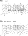
- FIG. 3 shows in an enlarged view the detail X of FIG. 2 ,
- This distraction becomes clear when looking at the magnetic field lines 3 in FIG. 3 with those in the FIG. 4 compares where also the field image is shown in the area of the end faces, in contrast to FIG. 3 but in FIG. 4 no permeable rings are present (prior art).
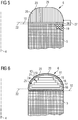
- FIG. 5 In the drawing of the FIG. 5 is a winding cover 6 enlarged in a cross-sectional view drawn. Shown is the front end of a winding 5.
- the winding cover 6 has the shape of a Torusabitess. This curved ring lies with a lying to the winding 5 flat side or annular surface 22 with the interposition of a Insulation layer 26 on the end face 10 of the winding 5. The end face 10 is thereby completely covered.
- the annular surface 23 facing away from the end face 10 is convexly curved in cross-section and provided with a flat 29 in a central region.
- the permeable ring 6 is formed here by a laminated core 25. The individual laminations of the laminated core 25 are aligned in the direction of the leg axis 4 and held together by an adhesive.
- An electrical contact device 27 contacts the laminated core 25 with an edge conductor 19 of the winding 5.
- FIG. 6 shows an embodiment of the invention, in which body 24 of the winding cover 6 consists of an electrical insulator (pressboard), in which a of a plurality of layers 15, 16, 17, 18 existing laminated core 25 is embedded.
- the laminated core 25 forms within the body part 24, the magnetically conductive portion 21.
- the body part 24 has the shape of a Torusabitess also in this embodiment of the invention.
- the lateral surface of the Torusabterrorisms is surrounded by an electric screen 13.
- the screen 13 consists of a Umbandelung with an electrically conductive sheet material, but may also be a wire spun or a coating.
- the screen 13 encloses here the entire surface of the body part 24 and forms an equipotential surface.
- the ring curvature 11 is dimensioned so that the electric field strength is minimized. As a result, the winding 5 is well protected against electrical flashovers on the front side.
- the individual layers, 15, 16, 17, 18 are formed by laminated cores and toroidal cores, which are each made of a ferromagnetic material and are arranged stacked stacked.
- the envelope surface of the electric screen 13 is surrounded by an electrical insulation 20.
- the convex side surface 23 points in the direction of the magnetic yoke, which is not shown here.
- the side surface 22 facing the winding 5 rests on the end face 10 of the winding 5.
- FIG. 7 shows another exemplary arrangement in which the permeable ring 6 is formed from a mold sintered part 28.
- the mold sintered part 28 again has the shape of a ring arched towards the yoke.
- the molding sintered part 28 is surrounded by a screen 13.
- the screen 13 is electrically connected to an electrical contact device 27 with a lying at the winding edge conductor 19 of the winding 5.
- an insulating layer 26 is disposed between the side surface 22 and the end face 10.
- FIG. 8 shows one opposite FIG. 7 slightly modified exemplary arrangement.
- the side surface 22 of the winding cover part 6 lying to the winding 5 is wider.
- the bead-shaped edge of the mold sintered part 28 is pulled down slightly to the left and right on the winding 5.
- the convex side surface 23 merges continuously into the side surface 22. There are therefore no sharp edges.
- the convex side surface 23 is provided in the region of the curvature 11 with an electric screen 13, which is produced by surface coating.
- the electrical potential of the screen 13 is again by means of the contact device 27 on the potential of the edge conductor 19 of the winding 5.
- the convex curvature of the curvature 11 is in each case formed so that the critical field strength for a electric flashover between winding and yoke is not reached during operation.
Landscapes
- Engineering & Computer Science (AREA)
- Power Engineering (AREA)
- Coils Of Transformers For General Uses (AREA)
- Coils Or Transformers For Communication (AREA)
- Insulating Of Coils (AREA)
- Regulation Of General Use Transformers (AREA)
Description
- Die Erfindung betrifft eine Wicklungsanordnung für einen Transformator oder eine Drossel, mit einem ringförmigen Wicklungs-Abdeckteil, der an einer Wicklung stirnseitig angeordnet ist, wobei eine der Wicklung zugewandte Seitenfläche des Wicklungs-Abdeckteils eine Stirnfläche der Wicklung überdeckt.
- Bei Transformatoren oder Drosseln hoher Nennleistung sind die elektrischen Wicklungen meist konzentrisch um einen Schenkel eines weichmagnetischen Kerns angeordnet und werden üblicherweise durch eine Presskonstruktion dauerhaft verspannt. Teil dieser Presskonstruktion sind so genannte Druck- oder Pressringe, mit denen die axiale Presskraft möglichst gleichmäßig auf die einzelnen Wicklungen aufgeteilt wird. Die Pressringe sind üblicherweise zwischen der Stirnseite der Wicklungen und dem zum Schenkel querliegenden Joch angeordnet.
- Ein solcher Pressring für einen Leistungstransformator ist beispielsweise aus der
US 3,750,070 bekannt. Dieser Pressring weist einen Körperteil auf, welcher die Form einer Kreisscheibe hat. Die beiden Stirnflächen der Kreisscheibe sind eben. Die Kreisscheibe liegt jeweils unter Zwischenlage eines Isolationsmaterials mit einer Seitenfläche an den Stirnflächen der Wicklungen an. Im Körperteil ausgebildete radial verlaufende Nuten sind mit Blechlammellen gefüllt, um möglichst verlustarm den magnetischen Streufluss zurück in den Transformatorkern zu leiten. - Auch aus der
US 3,366,907 geht ein ähnlicher Pressring hervor, der aus einem Blechwickel besteht. - Es ist bekannt, dass bei Betrieb eines Transformators oder einer Drossel Geräusche auftreten, die für den Betrieb unerwünscht sind. Man ist bestrebt, den magnetischen Fluss so zu führen, dass die Magnetostriktion und die während des Betriebs auf die Leiter der Wicklung einwirkenden Kräfte möglichst gering sind.
- Das Betriebsverhalten eines Transformators oder einer Drossel kann aber auch durch Spitzenwerte der elektrischen Spannung beeinträchtigt werden. Gefährdet sind insbesondere stirnseitig liegende Leiter der Wicklung. Wenn im Bereich der Stirnseite einer Wicklung die elektrische Feldstärke einen kritischen Wert übersteigt, kann es zu einem Überschlag zwischen Wicklung und Joch kommen. Dies kann die Isolation der Wicklung zerstören.
- Um die Isolation einer Wicklung bei einem Transformator vor kritischen Feldstärken zu schützen, schlägt die
DE 35 34 843 A1 einen Schirmring vor, der stirnseitig an der Wicklung angeordneter ist. Eine besondere Schutzwirkung kann dadurch erreicht werden, wenn der Schirmring mit dem jeweiligen Randleiter der Wicklung galvanisch verbunden ist. Der Schirmring ist an einer von der Wicklung abgewandten Seitenfläche gewölbt, so dass kritische Werte der elektrischen Feldstärke möglichst vermieden werden. Im Gegensatz zu den oben erwähnten Pressringen, die keinerlei elektrostatische Schutzwirkung besitzen, kommt diesem Schirmring ausschließlich eine elektrische Schutzfunktion zu. Ein Schirmring stellt ein gesondertes Bauteil dar und bedeutet damit einen zusätzlichen Aufwand bei der Herstellung. - Die
US 3 983 523 A offenbart eine Wicklungsanordnung nach dem Oberbegriff von Anspruch 1. - Darstellungen der Erfindung Der Erfindung liegt die Aufgabe zu Grunde, eine Wicklungsanordnung für einen Transformator oder für eine Drossel so anzugeben, dass auf möglichst einfache Weise das Betriebsverhalten verbessert wird und die Wicklung elektrostatisch gut geschützt ist.
- Gelöst wird diese Aufgabe durch eine Wicklungsanordnung mit den Merkmalen des Patentanspruchs 1. Vorteilhafte Ausgestaltungen der Erfindung sind in den abhängigen Patentansprüchen definiert.
- Die erfindungsgemäße Wicklungsanordnung weist an jeder Stirnfläche einer Wicklung einen ringförmigen Wicklungs-Abdeckteil auf, der zumindest in einem Teilbereich magnetisch leitfähige ausgebildet ist und eine von der Wicklung abgewandte konvexe Seitenfläche aufweist. Diese beiden Gestaltungsmerkmale, die magnetische Leitfähigkeit und die gewölbte Seitenfläche, wirken für eine Reduktion der Geräusche und eine elektrostatische Schutzwirkung förderlich zusammen:
- Zum einen wird durch die magnetisch leitfähige Ausbildung des Wicklungs-Abdeckteils erreicht, dass das magnetische Feld in Stirnbereich der Wicklung in eine axiale Richtung des Schenkelkerns gelenkt wird. Im Bereich der Stirnseite der Wicklung ist damit die radiale Komponente der magnetischen Feldstärke geringer. Die Rotationssymmetrie der Flussführung ist besser. Bei Betrieb eines Transformators oder einer Drossel kann dadurch die auf die Leiter wirkende Kraft, sowie Wirbelstromverluste in den Wicklungen und im Eisenpaket,
- niedrig gehalten werden. Dadurch treten weniger Geräusche und geringere Verluste auf. Eine geringe Geräuschemission ist insbesondere dann von Vorteil, wenn der
- Leistungstransformator oder die Drossel in der Nähe eines Wohnbereichs installiert ist. Da die Verlustverteilung in der Wicklung homogener wird, ergeben sich Vorteile in der thermischen Auslegung. Von großem Vorteil ist ferner, dass im Falle eines Kurzschlusses auf die elektrischen Wicklungen geringere axiale Kräfte wirken.
- Gleichzeitig wird durch die konvexe Ausbildung der zum Joch hin liegenden Seitenfläche des ringförmigen Wicklungs-Abdeckteils auf einfache Weise eine elektrostatische Abschirmung hergestellt. Im Stirnbereich der elektrischen Wicklung liegen die Äquipotenzialflächen nicht mehr eng beisammen, sondern weiter entfernt. Die Änderung des elektrischen Potenzials und damit der elektrischen Feldstärke ist geringer. Die stirnseitigen Kanten einer Wicklung sind gegenüber kritischen elektrischen Feldstärken besser geschützt, da die sanfte Krümmung der Seitenfläche das Problem der so genannten "Spitzenwirkung" entschärft. Damit ist im Ergebnis die Gefahr eines Überschlags zwischen Wicklung und magnetischen Kern verglichen mit einer ungeschirmten Wicklung geringer.
- Eine besonders einfache Konstruktion kann zum Beispiel dadurch gegeben sein, dass der ringförmige Wicklungs-Abdeckteil vollständig aus einem flach oder radial geschichteten Blechpaket oder einem Wickel eines ferromagnetischen Werkstoffs oder deren Kombination hergestellt ist. Die von der Wicklung entfernt liegende Seitenfläche des Blechpakets beziehungsweise des Winkels ist konvex ausgebildet. Damit fungiert das Wicklungs-Abdeckteil als magnetisches Flussführungsteil und als elektrische Abschirmung. Mit Vorteil können bei der Herstellung Bleche verwendet werden, wie sie bei der Fertigung des Kerns des Transformators beziehungsweise der Drossel ohnedies verwendet werden. Für die Handhabung kann es günstig sein, wenn die einzelnen Lamellen des torusförmigen Blechpakets durch einen Klebstoff zusammen gehalten werden.
- Eine Ausführungsform kann konstruiert sein, indem der Wicklungs-Abdeckteil einen aus einem Isolationswerkstoff gebildeten Körper aufweist in welchem eines oder mehrere Blechpakete eingelegt oder eingebettet sind. Der Körperteil kann die Form eines Torusabschnitts aufweisen, dessen Mantelfläche von einem elektrischen Schirm umhüllt ist. Die kapazitive Kopplung zwischen Schirm und Randleitern der Wicklung bewirkt einen elektrostatischen Abschirmeffekt. Für den Körperteil können mit Vorteil gebräuchliche Isolationswerkstoff, wie Pressspan und Holz verwendet werden. Eine besonders gute Abschirmwirkung lässt sich dadurch erzielen, indem das Blechpaket oder der Schirm, mittels einer an sich bekannten elektrischen Kontaktvorrichtung mit einem Randleiter der Wicklung elektrisch verbunden ist. Dadurch kann eine sehr wirksame elektrostatische Abschirmung und gleichzeitig eine günstige Beeinflussung des magnetischen Flusses erzielt werden.
- Es kann vorteilhaft sein, wenn das im Körperteil des Wicklungs-Abdeckteils eingebettete Blechpaket aus mehreren Lagen zusammengesetzt wird. Diese Lagen können in Stufen übereinander liegend angeordnet sein. Die einzelnen Lagen sind nach Form und Materialbeschaffenheit so ausgebildet, dass die Radialkomponente der magnetischen Flussdichte im Stirnbereich möglichst stark reduziert wird. Dadurch ist die durch Magnetostriktion hervorgerufene Schwingungsanregung und infolge davon die abgestrahlte Schallleistung geringer. Außerdem sind die Wirbelstromverluste im magnetischen Kern geringer. Im Kurzschlussfall wirken auf die Leiter der Wicklungen kleinere Kurzschlusskräfte.
- Der elektrische Schirm lässt sich auf einfache Weise durch eine Umbandelung des Körperteils mit einem elektrisch leitfähigen Bandmaterial oder mit einem Drahtgeflecht bzw. einem Drahtgespinst herstellen.
- Es ist aber auch denkbar, dass der elektrische Schirm dadurch hergestellt wird, indem die Oberfläche des Körperteils elektrisch leitfähig beschichtet wird, beispielsweise durch Auftrag eines leitfähigen Pulvers.
- Um den Wicklungs-Abdeckteil zumindest in einem Teilbereich magnetisch leitfähig auszubilden, können alternativ zum Blechpaket auch weichmagnetische Formsinterteile verwendet werden. Es kann das gesamte Wicklungs-Abdeckteil aus einem einzigen permeablen Massivkörper bestehen oder aus Sinterteilen zusammengesetzt sein. Der weichmagnetische Massivkörper oder die Sinterteile können auch in einem isolierenden Körperteil eingelegt oder eingebettet sein.
- Für die elektrostatische Abschirmwirkung kann es günstig sein, wenn das Formsinterteil die Form eines Torusabschnitts aufweist und an der zur Wicklung liegenden Seite wulstförmig heruntergezogen ist. Dabei kann es günstig sein, die zur Wicklung liegende Seitenfläche mit der konvexen Seitenfläche kontinuierlich ineinander übergehend auszubilden. Da keine scharfen Kanten vorhanden sind, wird die Spitzenwirkung der elektrischen Feldstärke gemindert. Die Gefahr eines elektrischen Überschlags zwischen Wicklung und Joch ist dadurch geringer.
- Für die Herstellung des Körperteils des Wicklungs-Abdeckteils kann neben den bereits erwähnten Isolierstoffen auch ein polymerer Werkstoff verwendet werden. Eine Ausbildung in Kunststoff hat beispielsweise den Vorteil, dass aufgrund der elastischen Eigenschaft des (Spritzt-)Gussmaterials die Schwingungsfortpflanzung gedämpft wird.
- In einer bevorzugten Ausführungsform kann vorgesehen sein, dass zwischen der Stirnfläche der Wicklung und gegenüberliegenden Seitenfläche des Wicklungs-Abdeckteils eine Isolationsschicht angeordnet ist.
- Bevorzugt ist auch eine Ausführung der Erfindung, bei der die Wicklung aus mehreren um eine Schenkelachse konzentrisch angeordneten Teilwicklungen besteht und jede Stirnseite dieser hohlzylindrischen Wicklungsteile jeweils von einem Wicklungs-Abdeckteil separat abgedeckt ist. Damit ist jeder Wicklungsteil zum benachbart liegenden Jochteil elektrostatisch gut abgeschirmt.
- In einer bevorzugten Konstruktion, sind die Wicklungs-Abdeckteile in einen Kraftfluss eingebunden, der von einer Abstütz- und Spannvorrichtung bewirkt wird, wobei die Abstütz- und Spannvorrichtung an einem oberen und/oder an einem unteren Jochteil des Transformators oder der Drossel abgestützt ist.
- Hierbei kann es günstig sein, wenn die konvexe Seitenfläche in einem mittleren Bereich eine Abflachung aufweist. Dadurch wird die Pressekraft auf eine entsprechend großen Kreisring übertragen.
- Zweckmäßig ist es, wenn bei der Herstellung des Blechpaketes oder des Ringbandkerns ein Blechmaterial verwendet wird, wie es auch bei der Herstellung des Jochs oder der Schenkel des Transformators beziehungsweise der Drossel verwendet wird.
- Zur weiteren Erläuterung der Erfindung wird im nachfolgenden Teil der Beschreibung auf die Zeichnungen Bezug genommen, in denen weitere vorteilhafte Ausgestaltungen, Einzelheiten und Weiterbildungen der Erfindung zu entnehmen sind.
Es zeigt: - Figur 1
- einen Leistungstransformator in einer Ansicht von oben in Richtung der Schenkelachse gesehen mit einer erfindungsgemäßen Wicklungsanordnung;
- Figur 2
- eine Schnittzeichnung gemäß der Linie A-A der
Figur 1 ; - Figur 3
- eine vergrößerte Darstellung des Detail X in
Figur 2 , in welcher der Verlauf der magnetischen Feldlinien im Bereich der Stirnflächen der Transformator-Wicklungen dargestellt ist, wobei erfindungsgemäße Wicklungs-Abdeckelemente vorhanden sind; - Figur 4
- eine Darstellung des Feldverlaufs wie in
Figur 3 , jedoch ohne die erfindungsgemäßen Wicklungs-Abdeckteile; - Figur 5
- ein Wicklungs-Abdeckteil, das aus Blechlammellen eines ferromagnetischen Material hergestellt ist, in einer vergrößerten Querschnittsdarstellung;
- Figur 6
- ein Wicklungs-Abdeckteil, wobei der magnetisch leitfähige Teilbereich durch Einbettung von Blechpaketen in dem Körperteil gebildet ist, in einer vergrößerten Querschnittsdarstellung;
- Figur 7
- ein Wicklungs-Abdeckteil, wobei der magnetisch leitfähige Teilbereich ein Formsinterteil ist, in einer vergrößerten Querschnittsdarstellung;
- Figur 8
- ein Wicklungs-Abdeckteil gemäß der
Figur 7 , bei dem ein Randbereich des Körperteils wulstförmig beidseits der Wicklung heruntergezogen ist. - Die
Figur 1 zeigt einen Transformator 1 im Bereich eines Transformatorschenkels 2, der eine aus mehreren Teilen bestehende Wicklung 5 trägt. Die einzelnen Teile der Wicklung 5 sind konzentrisch um eine Schenkelachse 4 angeordnet. Eine aus Isolationsmaterial (Pressspan) gebildete Abstütz- und Spannvorrichtung 8 drückt auf einen Pressring 7. Die Abstütz- und Spannvorrichtung 8 ist an Joch-Pressplatten 9 abgestützt. Der Transformatorschenkel 2 besteht aus hochpermeablem Elektroblech. - Die Zeichnung der
Figur 2 zeigt ein Schnittbild gemäß der Linie A-AFigur 1 . Die Abstütz- und Spannvorrichtung 8 presst die einzelnen Wicklungen 5 in axialer Richtung (Richtung der Schenkelachse 4) zusammen. Im Kraftfluss liegen dabei die Wicklungs-Abdeckteile 6, die jeweils an den Stirnflächen der Wicklungsteile 5 angeordnet sind. Wie unten stehend an Ausführungsbeispielen noch näher erläutert, bewirken die Wicklungs-Abdeckteile 6 einerseits eine Lenkung des magnetischen Flusses im Stirnbereich der Wicklung 5, andererseits stellen sie eine Barriere für einen elektrischen Überschlag zwischen Wicklung und Joch dar. Im Folgenden werden die Wicklungs-Abdeckteile 6 wegen ihrer magnetischen Leitfähigkeit auch kurz als permeable Ringe bezeichnet. Die von der Abstütz- und Spannvorrichtung 8 erzeugte Anpresskraft wird jeweils über einen Pressring 7 und mittels nicht näher dargestellter Kraftübertragungselemente 14 auf die permeablen Ringe 6 übertragen. Jeder dieser permeablen Ringe 6 überdeckt dabei jeweils eine Stirnfläche 10 einer Wicklung 5. - Die
Figur 3 zeigt in einer vergrößerten Darstellung das Detail X derFigur 2 . Wie bereits gesagt, bewirkt die magnetische leitfähige Ausbildung der Wicklungs-Abdeckteile 6, dass die magnetischen Feldlinien 3 in Richtung parallel zur Schenkelachse 4 gelenkt werden. Diese Ablenkung wird deutlich, wenn man die magnetischen Feldlinien 3 inFigur 3 mit denjenigen in derFigur 4 vergleicht, wo ebenfalls das Feldbild im Bereich der Stirnflächen dargestellt ist, im Gegensatz zuFigur 3 aber inFigur 4 keine permeablen Ringe vorhanden sind (Stand der Technik). - Im Ergebnis wird durch diesen Vergleich der
Figur 3 mit derFigur 4 deutlich, dass durch die erfindungsgemäße Wicklungsanordnung, bei der die Stirnflächen der Wicklungen 5 mit magnetisch leitfähigen Ringen 6 abgedeckt sind, sich die Radialkomponente der magnetischen Feldstärke im Bereich der Stirnflächen sich verringern lässt. Eine geringere Radialkomponente verbessert die Rotationssymmetrie des Flusses bezüglich der Schenkelachse 4. Die Streuverluste sind dadurch geringer. Die auf die einzelnen Leiter der Wicklung 5 jeweils wirkende axiale Kraft 12 ist dank der Erfindung geringer (die Größe der axialen Kraft ist inFigur 3 und inFigur 4 jeweils durch einen Pfeil dargestellt). Die geringere Krafteinwirkung auf die Leiter verbessert die Lastgeräuschemission. Im Falle eines elektrischen Kurzschluss ist die auf die Wicklung wirkende mechanische Belastung ebenfalls geringer. - In der Zeichnung der
Figur 5 ist ein Wicklungs-Abdeckelement 6 vergrößert in einer Querschnittsdarstellung gezeichnet. Dargestellt ist das stirnseitige Ende einer Wicklung 5. Das Wicklungs-Abdeckteil 6 hat die Form eines Torusabschnitts. Dieser gewölbte Ring liegt mit einer zur Wicklung 5 liegenden ebenen Seiten- oder Ringfläche 22 unter Zwischenlage einer Isolationsschicht 26 auf der Stirnfläche 10 der Wicklung 5 auf. Die Stirnfläche 10 ist dadurch vollständig abgedeckt. Die von der Stirnfläche 10 abgewandte Ringfläche 23 ist im Querschnitt gesehen konvex gekrümmt und in einem mittleren Bereich mit einer Abflachung 29 versehen. Der permeabel Ring 6 wird hier durch ein Blechpaket 25 gebildet. Die einzelnen Lamellen des Blechpakets 25 sind in Richtung der Schenkelachse 4 ausgerichtet und durch einen Klebstoff zusammengehalten. Eine elektrische Kontaktvorrichtung 27 kontaktiert das Blechpaket 25 mit einem Randleiter 19 der Wicklung 5. - Die
Figur 6 zeigt demgegenüber eine Ausführungsform der Erfindung, bei der Körper 24 des Wicklungs-Abdeckteils 6 aus einem elektrischen Isolator (Pressspan) besteht, in welchem ein aus mehreren Lagen 15, 16, 17, 18 bestehendes Blechpaket 25 eingebettet ist. Das Blechpaket 25 bildet innerhalb des Körperteils 24 den magnetisch leitfähigen Teilbereich 21. Der Körperteil 24 hat auch bei dieser Ausführungsform der Erfindung die Form eines Torusabschnitts. Die Mantelfläche des Torusabschnitts ist mit einem elektrischen Schirm 13 umgeben. Der Schirm 13 besteht aus einer Umbandelung mit einem elektrischen leitfähigen Bahnmaterial, kann aber auch ein Drahtgespinst oder eine Beschichtung sein. Der Schirm 13 umhüllt hier die gesamte Oberfläche des Körperteils 24 und bildet eine Äquipotenzialfläche. Die Ringwölbung 11 ist dabei so bemessen, dass die elektrische Feldstärke möglichst gering ist. Dadurch ist die Wicklung 5 stirnseitig gegenüber elektrischen Überschlägen gut geschützt. Die einzelnen Lagen, 15, 16, 17, 18 werden durch Blechpakete und Ringbandkerne gebildet, die jeweils aus einem ferromagnetischen Material hergestellt sind und abgestuft übereinander gestapelt angeordnet sind. Die Hüllfläche des elektrischen Schirms 13 ist mit einer elektrischen Isolation 20 umgeben. Die konvexe Seitenfläche 23 weist in Richtung des magnetischen Jochs, das hier nicht näher dargestellt ist. Die zur Wicklung 5 zeigende Seitenfläche 22 liegt auf der Stirnfläche 10 der Wicklung 5 auf. - Die
Figur 7 zeigt eine weitere beispielhafte Anordnung, bei der der permeable Ring 6 aus einem Formsinterteil 28 gebildet ist. Das Formsinterteil 28 weist wieder die Form eines zum Joch hin gewölbten Rings auf. Das Formsinterteil 28 ist mit einem Schirm 13 umgeben. Der Schirm 13 ist mit einer elektrischen Kontaktvorrichtung 27 mit einem am Wicklungsrand liegenden Leiter 19 der Wicklung 5 elektrisch verbunden. Auch hier ist zwischen der Seitenfläche 22 und der Stirnfläche 10 eine Isolationsschicht 26 angeordnet. - Die
Figur 8 zeigt eine gegenüberFigur 7 etwas abgewandelte beispielhafte Anordnung. Hier ist die zur Wicklung 5 liegende Seitenfläche 22 des Wicklungs-Abdeckteils 6 breiter ausgebildet. Der wulstförmige Rand des Formsinterteils 28 ist links und rechts an der Wicklung 5 etwas hinunter gezogen. Zwischen dem Formsinterteil 28 und der Stirnseite 10 der Wicklung 5 befindet sich eine Isolationsschicht 26. Die konvexe Seitenfläche 23 geht kontinuierlich in die Seitenfläche 22 über. Es gibt daher keine scharfen Kanten. Die konvexe Seitenfläche 23 ist im Bereich der Wölbung 11 mit einem elektrischen Schirm 13 versehen, der durch Oberflächenbeschichtung hergestellt ist. Das elektrische Potenzial des Schirms 13 liegt mittels der Kontaktvorrichtung 27 wieder auf dem Potenzial des Randleiters 19 der Wicklung 5. Die konvexe Krümmung der Wölbung 11 ist jeweils so ausgebildet, dass die kritische Feldstärke für einen elektrischen Überschlag zwischen Wicklung und Joch bei Betrieb nicht erreicht wird. -
- 1
- Transformator
- 2
- Transformatorschenkel
- 3
- Joch
- 4
- Schenkelachse
- 5
- Wicklung
- 6
- Wicklungs-Abdeckteil
- 7
- Druckring
- 8
- Abstütz- und Spannvorrichtung
- 9
- Joch-Pressplatten
- 10
- Stirnfläche
- 11
- Wölbung
- 12
- Axialkraft
- 13
- Schirm
- 14
- Kraftübertragungselemente
- 15
- Permeable Lage
- 16
- Permeable Lage
- 17
- Permeable Lage
- 18
- Permeable Lage
- 19
- Randleiter
- 20
- Isolation
- 21
- Teilbereich
- 22
- Seitenfläche, Ringfläche
- 23
- konvexe Seitenfläche, Ringfläche
- 24
- Körperteil
- 25
- Blechpaket
- 26
- Isolationsschicht
- 27
- Kontaktvorrichtung
- 28
- Formsinterteil
- 29
- Abflachung
Claims (12)
- Wicklungsanordnung für einen Transformator oder für eine Drossel, mit einem ringförmigen Wicklungs-Abdeckteil (6), der an einer Wicklung (5) stirnseitig angeordnet ist, wobei eine der Wicklung (5) zugewandte Seitenfläche (22) des Wicklungs-Abdeckteils (6) eine Stirnfläche (10) der Wicklung (5) überdeckt, wobei der ringförmige Wicklungs-Abdeckteil (6) einen Körperteil (24) aufweist, in welchem ein magnetisch leitfähiger Teilbereich (21), gebildet aus zumindest einem Blechpaket (25) oder zumindest einem permeablen Formsinterteil (28), angeordnet ist, und wobei der Körperteil (24) eine der Wicklung (5) abgewandte konvexe Seitenfläche (23) aufweist, und von einem elektrischen Schirm (13) umhüllt ist, dadurch gekennzeichnet, dass der magnetisch leitfähige Teilbereich (21) in dem Körperteil (24) eingebettet ist.
- Wicklungsanordnung nach Anspruch 1, dadurch gekennzeichnet, dass das zumindest eine Blechpaket (25) oder der Schirm (13) mittels einer elektrischen Kontaktvorrichtung (27) mit einem Randleiter der elektrischen Wicklung (4) verbunden ist.
- Wicklungsanordnung nach Anspruch 1, dadurch gekennzeichnet, dass das zumindest eine Blechpaket (25) aus gestuft übereinander liegenden Lagen (15, 16, 17, 18) zusammengesetzt ist.
- Wicklungsanordnung nach einem der Ansprüche 1 bis 3, dadurch gekennzeichnet, dass der elektrische Schirm (13) durch Umwickeln des ringförmigen Körperteils (24) mit einem elektrisch leitfähigen Band oder einem Drahtgeflecht hergestellt ist.
- Wicklungsanordnung nach Anspruch 1 bis 3, dadurch gekennzeichnet, dass der elektrische Schirm (13) durch Beschichtung der Oberfläche des Körperteils (24) gebildet ist.
- Wicklungsanordnung nach Anspruch 1, dadurch gekennzeichnet, dass das zumindest eine Formsinterteil (28) die Form eines Torusabschnitts aufweist, dass die der Wicklung (5) zugewandte Seitenfläche (22) des Wicklungs-Abdeckteils (6) die Stirnfläche (10) der Wicklung (5) überragt und mit der konvexen Seitenfläche (23) kontinuierlich ineinander übergehend ausgebildet ist.
- Wicklungsanordnung nach einem der Ansprüche 1 bis 5, dadurch gekennzeichnet, dass der Körperteil (24) aus einem polymeren Werkstoff hergestellt ist.
- Wicklungsanordnung nach einem der Ansprüche 1 bis 7, dadurch gekennzeichnet, dass zwischen der Stirnfläche (10) und der Seitenfläche (22) eine Isolationsschicht (26) angeordnet ist.
- Wicklungsanordnung nach einem der Ansprüche 1 bis 7, dadurch gekennzeichnet, dass die Wicklung (5) aus Wicklungsteilen gebildet ist, die konzentrisch um eine Schenkelachse (4) angeordnet sind und jede Stirnflächen (10) eines Wicklungsteils jeweils von einem zugeordneten Wicklungs-Abdeckteil (6) abgedeckt ist.
- Wicklungsanordnung nach Anspruch 9, dadurch gekennzeichnet, dass jedes Wicklungs-Abdeckteil (6) in einen in Richtung der Schenkelachse (4) wirkenden Kraftfluss eingebunden ist, der von einer Abstütz- und Spannvorrichtung (8) bewirkt wird, welche an einem oberen und/oder an einem unteren Joch (3) des Transformators oder der Drossel abgestützt ist.
- Wicklungsanordnung nach Anspruch 10, dadurch gekennzeichnet, dass jedes Wicklungs-Abdeckteil (6) an der konvexen Seitenfläche (23) mit einer Abflachung (29) versehen ist.
- Transformator oder Drossel mit einer Wicklungsanordnung nach Anspruch 1, dadurch gekennzeichnet, dass für das zumindest eine Blechpaket (25) das gleiche ferromagnetische Material verwendet wird, wie für den Kern des Transformators oder der Drossel.
Priority Applications (1)
| Application Number | Priority Date | Filing Date | Title |
|---|---|---|---|
| HRP20170753TT HRP20170753T1 (hr) | 2009-03-09 | 2009-03-09 | Uređenje zavojnice za transformator ili za reaktor |
Applications Claiming Priority (1)
| Application Number | Priority Date | Filing Date | Title |
|---|---|---|---|
| PCT/EP2009/052712 WO2010102659A1 (de) | 2009-03-09 | 2009-03-09 | Wicklungsanordnung für einen transformator oder für eine drossel |
Publications (2)
| Publication Number | Publication Date |
|---|---|
| EP2406799A1 EP2406799A1 (de) | 2012-01-18 |
| EP2406799B1 true EP2406799B1 (de) | 2017-03-08 |
Family
ID=41278499
Family Applications (1)
| Application Number | Title | Priority Date | Filing Date |
|---|---|---|---|
| EP09779123.0A Not-in-force EP2406799B1 (de) | 2009-03-09 | 2009-03-09 | Wicklungsanordnung für einen transformator oder für eine drossel |
Country Status (8)
| Country | Link |
|---|---|
| US (1) | US20110316662A1 (de) |
| EP (1) | EP2406799B1 (de) |
| KR (1) | KR101254155B1 (de) |
| CN (1) | CN102349122A (de) |
| BR (1) | BRPI0924432A2 (de) |
| HR (1) | HRP20170753T1 (de) |
| PL (1) | PL2406799T3 (de) |
| WO (1) | WO2010102659A1 (de) |
Families Citing this family (12)
| Publication number | Priority date | Publication date | Assignee | Title |
|---|---|---|---|---|
| US9754716B2 (en) * | 2011-08-01 | 2017-09-05 | General Electric Technology Gmbh | Current limiter |
| US20150109081A1 (en) * | 2013-10-21 | 2015-04-23 | Hammond Power Solutions, Inc. | Cast coil assembly with fins for an electrical transformer |
| EP3282457B1 (de) | 2016-08-09 | 2023-06-07 | Hitachi Energy Switzerland AG | Hochspannungskabel für eine wicklung und elektromagnetische induktionsvorrichtung damit |
| JP6463560B2 (ja) * | 2017-01-25 | 2019-02-06 | 三菱電機株式会社 | 筐体及び磁気センサ装置 |
| DE102017220423A1 (de) * | 2017-11-16 | 2019-05-16 | Siemens Aktiengesellschaft | Wicklungsanordnung |
| KR102001940B1 (ko) * | 2018-02-05 | 2019-07-22 | 효성중공업 주식회사 | 변압기용 소음저감장치 |
| EP3544033B1 (de) | 2018-03-20 | 2022-01-26 | Hitachi Energy Switzerland AG | Elektromagnetische induktionsvorrichtung mit verlustarmer wicklung |
| EP4268250A1 (de) * | 2020-12-24 | 2023-11-01 | Abb Schweiz Ag | Spule und transformator mit verbesserter elektromagnetischer abschirmung |
| EP4040455A1 (de) | 2021-02-05 | 2022-08-10 | Hitachi Energy Switzerland AG | Transformator mit wicklung |
| DE102021205654A1 (de) | 2021-06-02 | 2022-12-08 | Siemens Energy Global GmbH & Co. KG | Druckvorrichtung und Aktivteil eines Transformators |
| CN114898992A (zh) * | 2022-04-29 | 2022-08-12 | 武汉大学 | 一种66kV高电压等级、10MVA大容量的海上风电干式变压器 |
| EP4593045B1 (de) * | 2024-01-26 | 2026-05-20 | Hitachi Energy Ltd | Transformator |
Family Cites Families (10)
| Publication number | Priority date | Publication date | Assignee | Title |
|---|---|---|---|---|
| US2937349A (en) * | 1955-10-12 | 1960-05-17 | Gen Electric | Stationary induction electrical apparatus |
| US2907965A (en) * | 1956-08-24 | 1959-10-06 | Allis Chalmers Mfg Co | Reactor with end shielding having disk laminations |
| GB983481A (en) * | 1963-02-27 | 1965-02-17 | Gen Electric | Improvements in electrical reactors |
| US3281745A (en) * | 1963-09-10 | 1966-10-25 | Westinghouse Electric Corp | Corona and magnetic shielding structure for electrical transformers |
| US3774135A (en) * | 1972-12-21 | 1973-11-20 | Hitachi Ltd | Stationary induction apparatus |
| US3983523A (en) * | 1975-11-03 | 1976-09-28 | General Electric Company | Combination static plate and clamping ring |
| US4012706A (en) * | 1975-12-08 | 1977-03-15 | General Electric Company | Sheet-wound transformer coils |
| US4021764A (en) * | 1975-12-08 | 1977-05-03 | General Electric Company | Sheet-wound transformer coils with reduced edge heating |
| SE413716B (sv) * | 1978-05-02 | 1980-06-16 | Asea Ab | Krafttransformator eller reaktor |
| DE3243595C2 (de) * | 1982-11-25 | 1985-10-17 | Smit Transformatoren B.V., Nijmegen | Wicklungsanordnung für einen gasgekühlten Transformator |
-
2009
- 2009-03-09 EP EP09779123.0A patent/EP2406799B1/de not_active Not-in-force
- 2009-03-09 PL PL09779123T patent/PL2406799T3/pl unknown
- 2009-03-09 KR KR1020117023679A patent/KR101254155B1/ko not_active Expired - Fee Related
- 2009-03-09 WO PCT/EP2009/052712 patent/WO2010102659A1/de not_active Ceased
- 2009-03-09 CN CN2009801579678A patent/CN102349122A/zh active Pending
- 2009-03-09 HR HRP20170753TT patent/HRP20170753T1/hr unknown
- 2009-03-09 BR BRPI0924432A patent/BRPI0924432A2/pt not_active IP Right Cessation
- 2009-09-03 US US13/254,185 patent/US20110316662A1/en not_active Abandoned
Non-Patent Citations (1)
| Title |
|---|
| None * |
Also Published As
| Publication number | Publication date |
|---|---|
| HRP20170753T1 (hr) | 2017-07-28 |
| US20110316662A1 (en) | 2011-12-29 |
| WO2010102659A1 (de) | 2010-09-16 |
| EP2406799A1 (de) | 2012-01-18 |
| BRPI0924432A2 (pt) | 2016-01-26 |
| CN102349122A (zh) | 2012-02-08 |
| PL2406799T3 (pl) | 2017-08-31 |
| KR20110137349A (ko) | 2011-12-22 |
| KR101254155B1 (ko) | 2013-04-18 |
Similar Documents
| Publication | Publication Date | Title |
|---|---|---|
| EP2406799A1 (de) | Wicklungsanordnung für einen transformator oder für eine drossel | |
| EP2924697B1 (de) | Magnetkern mit plattenförmigem Streukörper und induktives Bauelement | |
| EP2546842A2 (de) | Spule zur Strombegrenzung | |
| WO2017016735A1 (de) | Verbesserter stator für eine elektrische maschine | |
| WO2016050515A1 (de) | Trockentransformatorkern | |
| WO1999044209A1 (de) | Mehrfachparallelleiter für elektrische maschinen und geräte | |
| DE102018005704B4 (de) | Drossel mit Eisenkernen und Spulen | |
| DE102005008302B4 (de) | Transformatorkern mit magnetischer Abschirmung | |
| EP2956947A1 (de) | Magnetisch vorgespannte drossel | |
| DE3108161C2 (de) | Wicklung für einen Transformator bzw. eine Drossel | |
| DE102018217904A1 (de) | Motorkomponente sowie Elektromotor | |
| DE102006026466B3 (de) | Induktives elektrisches Element, insbesondere Transformator, Übertrager, Drossel, Filter und Wickelgut | |
| EP3018664B1 (de) | Magnetkern für eine elektrische Induktionseinrichtung | |
| WO2014135205A1 (de) | Elektrischer transformator oder drossel sowie wicklungsanordnung mit abstandshalter | |
| EP0959484A2 (de) | Abschirmung für Summenstrom-Wandleranordnung für Fehlerstrom-Schutzschalter | |
| EP4189709B1 (de) | Transformator | |
| DE10062091C1 (de) | Induktives Bauelement | |
| DE202012104824U1 (de) | Vorrichtung zur Erfassung von Fehlerströmen | |
| EP4046173B1 (de) | Formadaptive halterung für eine kernausführung und damit hergestelltes induktives bauelement | |
| DE102012203337B4 (de) | Summenstromwandler und elektrisches Schutzschaltgerät | |
| DE102011082170A1 (de) | Stromwandler | |
| EP3824486A1 (de) | Kernanordnung mit magnetischen eigenschaften für eine elektrische vorrichtung und drossel mit einer derartigen kernanordnung | |
| AT413158B (de) | Elektrische maschine mit einer abschirmeinrichtung gegen magnetischen streufluss | |
| WO2019149469A1 (de) | Elektrisches gerät mit pressplatten zum verspannen eines magnetisierbaren kerns | |
| DE102017223839A1 (de) | Magnetkern mit Rückschlussschenkel |
Legal Events
| Date | Code | Title | Description |
|---|---|---|---|
| PUAI | Public reference made under article 153(3) epc to a published international application that has entered the european phase |
Free format text: ORIGINAL CODE: 0009012 |
|
| 17P | Request for examination filed |
Effective date: 20110707 |
|
| AK | Designated contracting states |
Kind code of ref document: A1 Designated state(s): AT BE BG CH CY CZ DE DK EE ES FI FR GB GR HR HU IE IS IT LI LT LU LV MC MK MT NL NO PL PT RO SE SI SK TR |
|
| DAX | Request for extension of the european patent (deleted) | ||
| RAP1 | Party data changed (applicant data changed or rights of an application transferred) |
Owner name: SIEMENS AG OESTERREICH |
|
| RAP1 | Party data changed (applicant data changed or rights of an application transferred) |
Owner name: SIEMENS AKTIENGESELLSCHAFT |
|
| GRAP | Despatch of communication of intention to grant a patent |
Free format text: ORIGINAL CODE: EPIDOSNIGR1 |
|
| INTG | Intention to grant announced |
Effective date: 20161004 |
|
| STAA | Information on the status of an ep patent application or granted ep patent |
Free format text: STATUS: GRANT OF PATENT IS INTENDED |
|
| GRAS | Grant fee paid |
Free format text: ORIGINAL CODE: EPIDOSNIGR3 |
|
| GRAA | (expected) grant |
Free format text: ORIGINAL CODE: 0009210 |
|
| STAA | Information on the status of an ep patent application or granted ep patent |
Free format text: STATUS: THE PATENT HAS BEEN GRANTED |
|
| AK | Designated contracting states |
Kind code of ref document: B1 Designated state(s): AT BE BG CH CY CZ DE DK EE ES FI FR GB GR HR HU IE IS IT LI LT LU LV MC MK MT NL NO PL PT RO SE SI SK TR |
|
| REG | Reference to a national code |
Ref country code: GB Ref legal event code: FG4D Free format text: NOT ENGLISH |
|
| REG | Reference to a national code |
Ref country code: CH Ref legal event code: EP Ref country code: AT Ref legal event code: REF Ref document number: 874196 Country of ref document: AT Kind code of ref document: T Effective date: 20170315 |
|
| REG | Reference to a national code |
Ref country code: IE Ref legal event code: FG4D Free format text: LANGUAGE OF EP DOCUMENT: GERMAN |
|
| REG | Reference to a national code |
Ref country code: DE Ref legal event code: R096 Ref document number: 502009013728 Country of ref document: DE |
|
| REG | Reference to a national code |
Ref country code: HR Ref legal event code: TUEP Ref document number: P20170753 Country of ref document: HR |
|
| REG | Reference to a national code |
Ref country code: NL Ref legal event code: FP |
|
| REG | Reference to a national code |
Ref country code: SE Ref legal event code: TRGR |
|
| REG | Reference to a national code |
Ref country code: LT Ref legal event code: MG4D |
|
| REG | Reference to a national code |
Ref country code: HR Ref legal event code: T1PR Ref document number: P20170753 Country of ref document: HR |
|
| PG25 | Lapsed in a contracting state [announced via postgrant information from national office to epo] |
Ref country code: NO Free format text: LAPSE BECAUSE OF FAILURE TO SUBMIT A TRANSLATION OF THE DESCRIPTION OR TO PAY THE FEE WITHIN THE PRESCRIBED TIME-LIMIT Effective date: 20170608 Ref country code: FI Free format text: LAPSE BECAUSE OF FAILURE TO SUBMIT A TRANSLATION OF THE DESCRIPTION OR TO PAY THE FEE WITHIN THE PRESCRIBED TIME-LIMIT Effective date: 20170308 Ref country code: GR Free format text: LAPSE BECAUSE OF FAILURE TO SUBMIT A TRANSLATION OF THE DESCRIPTION OR TO PAY THE FEE WITHIN THE PRESCRIBED TIME-LIMIT Effective date: 20170609 Ref country code: LT Free format text: LAPSE BECAUSE OF FAILURE TO SUBMIT A TRANSLATION OF THE DESCRIPTION OR TO PAY THE FEE WITHIN THE PRESCRIBED TIME-LIMIT Effective date: 20170308 |
|
| RAP2 | Party data changed (patent owner data changed or rights of a patent transferred) |
Owner name: SIEMENS AKTIENGESELLSCHAFT |
|
| PG25 | Lapsed in a contracting state [announced via postgrant information from national office to epo] |
Ref country code: LV Free format text: LAPSE BECAUSE OF FAILURE TO SUBMIT A TRANSLATION OF THE DESCRIPTION OR TO PAY THE FEE WITHIN THE PRESCRIBED TIME-LIMIT Effective date: 20170308 Ref country code: ES Free format text: LAPSE BECAUSE OF FAILURE TO SUBMIT A TRANSLATION OF THE DESCRIPTION OR TO PAY THE FEE WITHIN THE PRESCRIBED TIME-LIMIT Effective date: 20170308 Ref country code: BG Free format text: LAPSE BECAUSE OF FAILURE TO SUBMIT A TRANSLATION OF THE DESCRIPTION OR TO PAY THE FEE WITHIN THE PRESCRIBED TIME-LIMIT Effective date: 20170608 |
|
| REG | Reference to a national code |
Ref country code: CH Ref legal event code: NV Representative=s name: SIEMENS SCHWEIZ AG, CH Ref country code: CH Ref legal event code: PCOW Free format text: NEW ADDRESS: WERNER-VON-SIEMENS-STRASSE 1, 80333 MUENCHEN (DE) |
|
| PG25 | Lapsed in a contracting state [announced via postgrant information from national office to epo] |
Ref country code: RO Free format text: LAPSE BECAUSE OF FAILURE TO SUBMIT A TRANSLATION OF THE DESCRIPTION OR TO PAY THE FEE WITHIN THE PRESCRIBED TIME-LIMIT Effective date: 20170308 Ref country code: IT Free format text: LAPSE BECAUSE OF FAILURE TO SUBMIT A TRANSLATION OF THE DESCRIPTION OR TO PAY THE FEE WITHIN THE PRESCRIBED TIME-LIMIT Effective date: 20170308 Ref country code: EE Free format text: LAPSE BECAUSE OF FAILURE TO SUBMIT A TRANSLATION OF THE DESCRIPTION OR TO PAY THE FEE WITHIN THE PRESCRIBED TIME-LIMIT Effective date: 20170308 Ref country code: SK Free format text: LAPSE BECAUSE OF FAILURE TO SUBMIT A TRANSLATION OF THE DESCRIPTION OR TO PAY THE FEE WITHIN THE PRESCRIBED TIME-LIMIT Effective date: 20170308 Ref country code: CZ Free format text: LAPSE BECAUSE OF FAILURE TO SUBMIT A TRANSLATION OF THE DESCRIPTION OR TO PAY THE FEE WITHIN THE PRESCRIBED TIME-LIMIT Effective date: 20170308 |
|
| REG | Reference to a national code |
Ref country code: CH Ref legal event code: PL |
|
| PG25 | Lapsed in a contracting state [announced via postgrant information from national office to epo] |
Ref country code: IS Free format text: LAPSE BECAUSE OF FAILURE TO SUBMIT A TRANSLATION OF THE DESCRIPTION OR TO PAY THE FEE WITHIN THE PRESCRIBED TIME-LIMIT Effective date: 20170708 Ref country code: PT Free format text: LAPSE BECAUSE OF FAILURE TO SUBMIT A TRANSLATION OF THE DESCRIPTION OR TO PAY THE FEE WITHIN THE PRESCRIBED TIME-LIMIT Effective date: 20170710 |
|
| REG | Reference to a national code |
Ref country code: DE Ref legal event code: R097 Ref document number: 502009013728 Country of ref document: DE |
|
| REG | Reference to a national code |
Ref country code: IE Ref legal event code: MM4A |
|
| PLBE | No opposition filed within time limit |
Free format text: ORIGINAL CODE: 0009261 |
|
| STAA | Information on the status of an ep patent application or granted ep patent |
Free format text: STATUS: NO OPPOSITION FILED WITHIN TIME LIMIT |
|
| REG | Reference to a national code |
Ref country code: FR Ref legal event code: ST Effective date: 20171228 |
|
| PG25 | Lapsed in a contracting state [announced via postgrant information from national office to epo] |
Ref country code: MC Free format text: LAPSE BECAUSE OF FAILURE TO SUBMIT A TRANSLATION OF THE DESCRIPTION OR TO PAY THE FEE WITHIN THE PRESCRIBED TIME-LIMIT Effective date: 20170308 Ref country code: FR Free format text: LAPSE BECAUSE OF NON-PAYMENT OF DUE FEES Effective date: 20170509 Ref country code: LU Free format text: LAPSE BECAUSE OF NON-PAYMENT OF DUE FEES Effective date: 20170309 Ref country code: DK Free format text: LAPSE BECAUSE OF FAILURE TO SUBMIT A TRANSLATION OF THE DESCRIPTION OR TO PAY THE FEE WITHIN THE PRESCRIBED TIME-LIMIT Effective date: 20170308 |
|
| 26N | No opposition filed |
Effective date: 20171211 |
|
| PG25 | Lapsed in a contracting state [announced via postgrant information from national office to epo] |
Ref country code: IE Free format text: LAPSE BECAUSE OF NON-PAYMENT OF DUE FEES Effective date: 20170309 Ref country code: CH Free format text: LAPSE BECAUSE OF NON-PAYMENT OF DUE FEES Effective date: 20170331 Ref country code: LI Free format text: LAPSE BECAUSE OF NON-PAYMENT OF DUE FEES Effective date: 20170331 Ref country code: SI Free format text: LAPSE BECAUSE OF FAILURE TO SUBMIT A TRANSLATION OF THE DESCRIPTION OR TO PAY THE FEE WITHIN THE PRESCRIBED TIME-LIMIT Effective date: 20170308 |
|
| REG | Reference to a national code |
Ref country code: HR Ref legal event code: PNAN Ref document number: P20170753 Country of ref document: HR Owner name: SIEMENS AKTIENGESELLSCHAFT, DE |
|
| REG | Reference to a national code |
Ref country code: BE Ref legal event code: MM Effective date: 20170331 |
|
| PGFP | Annual fee paid to national office [announced via postgrant information from national office to epo] |
Ref country code: GB Payment date: 20180312 Year of fee payment: 10 |
|
| PG25 | Lapsed in a contracting state [announced via postgrant information from national office to epo] |
Ref country code: BE Free format text: LAPSE BECAUSE OF NON-PAYMENT OF DUE FEES Effective date: 20170331 |
|
| PG25 | Lapsed in a contracting state [announced via postgrant information from national office to epo] |
Ref country code: MT Free format text: LAPSE BECAUSE OF FAILURE TO SUBMIT A TRANSLATION OF THE DESCRIPTION OR TO PAY THE FEE WITHIN THE PRESCRIBED TIME-LIMIT Effective date: 20170308 |
|
| REG | Reference to a national code |
Ref country code: HR Ref legal event code: ODRP Ref document number: P20170753 Country of ref document: HR Payment date: 20190222 Year of fee payment: 11 |
|
| PG25 | Lapsed in a contracting state [announced via postgrant information from national office to epo] |
Ref country code: HU Free format text: LAPSE BECAUSE OF FAILURE TO SUBMIT A TRANSLATION OF THE DESCRIPTION OR TO PAY THE FEE WITHIN THE PRESCRIBED TIME-LIMIT; INVALID AB INITIO Effective date: 20090309 |
|
| PG25 | Lapsed in a contracting state [announced via postgrant information from national office to epo] |
Ref country code: CY Free format text: LAPSE BECAUSE OF NON-PAYMENT OF DUE FEES Effective date: 20170308 |
|
| GBPC | Gb: european patent ceased through non-payment of renewal fee |
Effective date: 20190309 |
|
| PG25 | Lapsed in a contracting state [announced via postgrant information from national office to epo] |
Ref country code: MK Free format text: LAPSE BECAUSE OF FAILURE TO SUBMIT A TRANSLATION OF THE DESCRIPTION OR TO PAY THE FEE WITHIN THE PRESCRIBED TIME-LIMIT Effective date: 20170308 |
|
| PG25 | Lapsed in a contracting state [announced via postgrant information from national office to epo] |
Ref country code: GB Free format text: LAPSE BECAUSE OF NON-PAYMENT OF DUE FEES Effective date: 20190309 |
|
| REG | Reference to a national code |
Ref country code: HR Ref legal event code: ODRP Ref document number: P20170753 Country of ref document: HR Payment date: 20200228 Year of fee payment: 12 |
|
| PG25 | Lapsed in a contracting state [announced via postgrant information from national office to epo] |
Ref country code: TR Free format text: LAPSE BECAUSE OF FAILURE TO SUBMIT A TRANSLATION OF THE DESCRIPTION OR TO PAY THE FEE WITHIN THE PRESCRIBED TIME-LIMIT Effective date: 20170308 |
|
| PGFP | Annual fee paid to national office [announced via postgrant information from national office to epo] |
Ref country code: AT Payment date: 20200210 Year of fee payment: 12 Ref country code: NL Payment date: 20200311 Year of fee payment: 12 Ref country code: PL Payment date: 20200224 Year of fee payment: 12 Ref country code: SE Payment date: 20200317 Year of fee payment: 12 |
|
| PGFP | Annual fee paid to national office [announced via postgrant information from national office to epo] |
Ref country code: HR Payment date: 20200228 Year of fee payment: 12 |
|
| PGFP | Annual fee paid to national office [announced via postgrant information from national office to epo] |
Ref country code: DE Payment date: 20200519 Year of fee payment: 12 |
|
| REG | Reference to a national code |
Ref country code: DE Ref legal event code: R081 Ref document number: 502009013728 Country of ref document: DE Owner name: SIEMENS ENERGY GLOBAL GMBH & CO. KG, DE Free format text: FORMER OWNER: SIEMENS AKTIENGESELLSCHAFT, 80333 MUENCHEN, DE |
|
| REG | Reference to a national code |
Ref country code: DE Ref legal event code: R119 Ref document number: 502009013728 Country of ref document: DE |
|
| REG | Reference to a national code |
Ref country code: HR Ref legal event code: PBON Ref document number: P20170753 Country of ref document: HR Effective date: 20210309 |
|
| REG | Reference to a national code |
Ref country code: NL Ref legal event code: MM Effective date: 20210401 |
|
| REG | Reference to a national code |
Ref country code: AT Ref legal event code: MM01 Ref document number: 874196 Country of ref document: AT Kind code of ref document: T Effective date: 20210309 |
|
| PG25 | Lapsed in a contracting state [announced via postgrant information from national office to epo] |
Ref country code: NL Free format text: LAPSE BECAUSE OF NON-PAYMENT OF DUE FEES Effective date: 20210401 Ref country code: AT Free format text: LAPSE BECAUSE OF NON-PAYMENT OF DUE FEES Effective date: 20210309 Ref country code: SE Free format text: LAPSE BECAUSE OF NON-PAYMENT OF DUE FEES Effective date: 20210310 Ref country code: DE Free format text: LAPSE BECAUSE OF NON-PAYMENT OF DUE FEES Effective date: 20211001 Ref country code: HR Free format text: LAPSE BECAUSE OF NON-PAYMENT OF DUE FEES Effective date: 20210309 |
|
| PG25 | Lapsed in a contracting state [announced via postgrant information from national office to epo] |
Ref country code: PL Free format text: LAPSE BECAUSE OF NON-PAYMENT OF DUE FEES Effective date: 20210309 |