EP0959484A2 - Abschirmung für Summenstrom-Wandleranordnung für Fehlerstrom-Schutzschalter - Google Patents
Abschirmung für Summenstrom-Wandleranordnung für Fehlerstrom-Schutzschalter Download PDFInfo
- Publication number
- EP0959484A2 EP0959484A2 EP99108970A EP99108970A EP0959484A2 EP 0959484 A2 EP0959484 A2 EP 0959484A2 EP 99108970 A EP99108970 A EP 99108970A EP 99108970 A EP99108970 A EP 99108970A EP 0959484 A2 EP0959484 A2 EP 0959484A2
- Authority
- EP
- European Patent Office
- Prior art keywords
- shield
- shielding
- converter arrangement
- secondary winding
- toroidal core
- Prior art date
- Legal status (The legal status is an assumption and is not a legal conclusion. Google has not performed a legal analysis and makes no representation as to the accuracy of the status listed.)
- Withdrawn
Links
Images


Classifications
-
- H—ELECTRICITY
- H01—ELECTRIC ELEMENTS
- H01H—ELECTRIC SWITCHES; RELAYS; SELECTORS; EMERGENCY PROTECTIVE DEVICES
- H01H83/00—Protective switches, e.g. circuit-breaking switches, or protective relays operated by abnormal electrical conditions otherwise than solely by excess current
- H01H83/14—Protective switches, e.g. circuit-breaking switches, or protective relays operated by abnormal electrical conditions otherwise than solely by excess current operated by imbalance of two or more currents or voltages, e.g. for differential protection
- H01H83/144—Protective switches, e.g. circuit-breaking switches, or protective relays operated by abnormal electrical conditions otherwise than solely by excess current operated by imbalance of two or more currents or voltages, e.g. for differential protection with differential transformer
Definitions
- the present invention relates to a total current converter arrangement, for the detection of residual currents, particularly suitable for residual current switches and in which a shield for the purpose of reducing Malfunction of this arrangement is provided.
- Total current transformer arrangements for in particular residual current circuit breakers work on the induction principle.
- Such Arrangements contain a highly permeable / ferromagnetic Toroid with a (secondary) winding on it.
- the primary power line (forward and return conductors) for which the Total current to be monitored is through the inside of this Toroidal led.
- One in the vicinity of the power line in the Resulting magnetic core area occurring Alternating field can be created using the in the winding of the toroid induced electrical voltage can be detected.
- Such a Magnetic flux occurs when in the outward conductor and in Return conductor of the one led through the inside of the toroid Power line currents of different sizes flow. Something like that occurs when there is a fault current.
- DE-C-42 15 900 is intended to equalize the forward and return conductors of the power line by multiply symmetrical division with regard to a dipole effect on the toroidal core, as described in DE-A 196 53 552.2 (GR 96 P 2668),
- Another solution to this problem is to position existing anisotropy (s) in the toroid (the secondary coil) and / or winding number density inhomogeneity (s) of the secondary winding in an error-correcting manner, that is to say to use an asymmetry effect which is undesirable per se for error correction.
- the object of the present invention is to specify measures with those for the AC case at least one minimization of the effect that is to be achieved as above Defects of such a total current converter arrangement described, especially faulty circuit breaker trips leads. This is intended in particular with the invention for residual current switches for higher nominal currents (approx greater than 63 A.)
- the solution principle of the invention is based on the idea the effectiveness of shielding the toroid, in particular the shielding factor with regard to the dipole field that occurs, for the AC case to increase significantly.
- the unified principle of solution of the invention is in shielding with slit effect, i.e. with at least one Slot, the weakening of the shielding effect by the occurring Switching off or at least minimizing eddy currents, be it by preventing any eddy currents or at least be minimized, or by the fact that only such Eddy currents allowed or favored in the shield be a weakening of the dipole field in the toroid effect and thus increase the effectiveness of the shield.
- Shielding induced eddy currents is for one (of the type after also known) shielding of the toroid and its winding provided to use a material that compared to the usual for shielding magnetic fields materials used greatly reduced electrical conductivity having.
- a material is e.g. a (ferrite) sintered material, as it is for e.g. Pot cores from coils and the like.
- the shield according to the invention as in axial and / or Radial direction sheet metal structure with electrical insulation effect between the sheets lying on top of each other to execute. It is for the thickness of the respective shells choose such a dimension for the wall of the shield, that this material thickness the penetration depth ⁇ of the occurring Eddy currents in the material of the respective wall are not or at least not significantly exceeds. For the sheets is a thickness much smaller than the penetration depth choose.
- the material and frequency dependent penetration depth is to be determined by a specialist according to the known rules.
- an outermost shell may also be provided, the made of electrically highly conductive and low-permeable material, e.g. made of copper.
- the ones described above Solution principles according to the invention can be used together with simpler or double slitting of the shield be. This applies in particular to the latter Proposal with additional electrically highly conductive outermost shell.
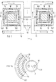
- FIG 1 shows one Section I-I to Figure 1.
- the ring core is made of one permeable material known to be used for such purposes, such as iron, a ferrite or the like.
- With 16 is the wound on a bobbin 15, on the Ring core 14 attached (secondary) winding designated.
- With 140 is a shield designated here with the slot 141 is executed. Through the slot is able to unbalanced current flow in the power line 10 resulting resulting magnetic flux inside the shield 140 in the effective range of the toroidal core 14 with the Winding 16 penetrate. With W are occurring (according to the invention at least largely prevented / minimized) eddy currents shown and labeled in shield 140.
- FIG. 1a shows the sectional view associated with FIG. 1, with which a complete picture, the embodiment of the Figure 1 regarding, can win.
- the shield 140 is corresponding the principle underlying the invention for the shield 140 to be effected outside the slot 141 Effect provided that this shield 140 from a Material with a relatively low specific electrical conductivity consists. This is particularly suitable per se ferromagnetic sintered material due to its sintered structure is relatively specifically high-impedance.
- reference number 141 ' indicates that at the place of this reference numeral 141 'a second Slit, such as how slot 141 may be provided.
- the shielding 140 again from two half shells, which on their two edges at a distance from the respective slot 141, 141 ' face each other.
- FIG. 2 shows a second structure according to the invention several nested shields 140, 240, 340 with slot 141.
- the other reference numerals correspond those of FIG. 1 already described.
- the individual shells of the shields 140, 240, 340 are arranged electrically isolated from each other. As for Figure 1 described, the double slitting shown here 141, 141 'may be provided.
- the slot can be positioned either inside or outside be.
- the height of the slot (s) can also be selected.
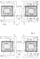
- FIG. 3 shows a third embodiment of the invention with axially laminated magnetic shielding.
- the axially aligned wall portions 140a, 140b consist of thin rings lying one on top of the other, which are made, for example, of sheet metal (which is what the designation says).
- the wall portions 140b and 140c of the shield are also preferably made of sheet metal, ie they consist of sheets of the material of the shield lying on top of one another.
- the surfaces of these sheet metal rings 140a and sheet metal disks 140b, 140c are made electrically insulating. In this way, eddy current effects can be made be significantly reduced in the material of the shield.
- 141a and 141b are two slots here.
- the sheet metal But construction makes a slit, as for the Designs of Figures 1, 2 and 6 are necessary for Versions of Figures 3 to 5 can be dispensed with.
- a variation of the third embodiment of the invention shows Figure 4 with radially laminated magnetic shielding.
- 140e and 140f are two coaxial cylindrical sleeves designated, e.g. wrapped from a sheet of metal are.
- the surface of the sheet metal strip is also electrical here insulated.
- 140g and 140h are the ring-shaped Cover for these nested sleeves 140e and Designated 140f. These are e.g. likewise, here from narrow Sheet metal strip, wrapped.
- Such an embodiment according to Figure 4 fulfills the requirement placed on the invention Solving the problem of high effectiveness of shielding.
- FIG. 5 shows a further variation of the third embodiment of the invention with the lids 140g and 140h of the shield according to FIG. 4 and an embodiment the cylindrical sleeves 140a, 140b in the manner of the figure 3.
- the invention can also be an embodiment, not shown with sleeves 140e and 140f, these preferably in Wrap shape, and with lids 140c and 140d, respectively Formed washers, combined to be formed.
- FIG. 6 shows a further developed embodiment according to of the invention with e.g. a shield 140.
- a shield like the one shown in FIG Figures 2 to 5 described can be provided.
- 440 is in Figure 6 denotes an additional outermost shield, the made of electrically good conductive material, e.g. made of copper.
- Shield 440 has at least one slot 141.
- Slits 141 should be provided in all embodiments louvers of the invention. But you can also use not or only slightly permeable, but definitely electrical non-conductive material, for example as a spacer (more or less).
- the above description and in particular the embodiments show a primary power line with parallel side by side guided outward and return conductors.
- the invention is also suitable for use with a coaxial primary power line, if you just put this coaxial conductor in close to the sum current converter arrangement, i.e. of the residual current circuit breaker having. This is because even in such a case dipole components of the magnetic AC field with a correspondingly adverse effect exact fault closure triggering occur.
Landscapes
- Engineering & Computer Science (AREA)
- Power Engineering (AREA)
- Regulation Of General Use Transformers (AREA)
- Emergency Protection Circuit Devices (AREA)
Abstract
Description
- Figur 1
- zeigt eine Ausführungsform mit einer Abschirmung, die aus einem Material besteht, das Wirbelströme jeglicher Richtung in derselben minimiert. Die Figur 1 zeigt einen Schnitt in einer Ebene mit der Achse A des Aufbaus.
- Figur 1a
- zeigt zur Figur 1 einen Schnitt senkrecht zu dieser Achse A.
- Figur 2
- zeigt (in einem Schnitt wie Figur 1) eine Ausführungsform der Erfindung mit mehrschaligem Aufbau der Abschirmung.
- Figur 3
- zeigt eine Ausführungsform mit einem in Axialrichtung (d.h. senkrecht zur Achse A) geblechtem Aufbau der Abschirmung.
- Figur 4
- zeigt eine Ausführungsform mit radial geblechtem Aufbau der Abschirmung.
- Figur 5
- zeigt eine Ausführungsform mit teilweise radial und mit teilweise axial geblechtem Aufbau der Abschirmung und
- Figur 6
- zeigt eine Ausführungsform mit einer Abschirmung nach Art einer der Ausführungsformen der Figuren 2 bis 5 bezüglich der magnetischen Abschirmung und mit zusätzlich einer diese magnetische Abschirmung umgebenden (weiteren) elektrischen Abschirmung.
Claims (9)
- Summenstrom-Wandleranordnung für eine Primär-Stromleitung (10),
mit einem Ringkern (14) mit Sekundärwicklung (16),
wobei Ringkern und Sekundärwicklung innerhalb einer aus hochpermeablem Material bestehenden Abschirmung (140) mit Schlitzwirkung (141) angeordnet sind,
dadurch gekennzeichnet,
daß für Wechselstrombetrieb der effektiv wirksame Abschirmtaktor durch Wahl eines außerdem auch elektrisch hochohmigen Materials für die Abschirmung vergrößert ist. - Wandleranordnung nach Anspruch 1,
dadurch gekennzeichnet,
daß die Abschirmung (140) aus hochpermeablen Sinterwerkstoff besteht. (Figur 1) - Summenstrom-Wandleranordnung für eine Primär-Stromleitung (10),
mit einem Ringkern (14) mit Sekundärwicklung (16),
wobei Ringkern und Sekundärwicklung innerhalb einer aus hochpermeablem Material bestehenden Abschirmung (140) mit Schlitzwirkung (141) angeordnet sind,
dadurch gekennzeichnet,
daß für Wechselstrombetrieb für vergrößerten effektiv wirksamen Abschirmfaktor die Abschirmung einen mehrschaligen Aufbau mit elektrisch gegeneinander isolierten Einzelschalen (140, 240, 340) hat, wobei die Wanddicke (d) der Einzelschalen die Eindringtiefe δ wenigstens nicht wesentlich übersteigt. (Figur 2) - Summenstrom-Wandleranordnung für eine Primär-Stromleitung (10),
mit einem Ringkern (14) mit Sekundärwicklung (16),
wobei Ringkern und Sekundärwicklung innerhalb einer aus permeablem Material bestehenden Abschirmung (140) mit Schlitzwirkung (141) angeordnet sind,
dadurch gekennzeichnet,
daß für Wechselstrombetrieb für vergrößerten effektiv wirksamen Abschirmfaktor die Abschirmung (140) einen geblechten Aufbau mit elektrischer Isolation der Bleche gegeneinander hat, wobei die Dicke der Bleche uni ein Vielfaches kleiner als die Eindringtiefe δ ist. (Figuren 3 bis 5) - Wandleranordnung nach Anspruch 4, dadurch gekennzeichnet,
daß die Blechung in Radialrichtung der Anordnung ausgeführt ist. (Figur 3) - Wandleranordnung nach Anspruch 4,
dadurch gekennzeichnet,
daß die Blechung in Axialrichtung der Anordnung ausgeführt ist. (Figur 5) - Wandleranordnung nach einem der Ansprüche 4, 5 oder 6, gekennzeichnet durch eine teilweise radial und teilweise axial ausgeführte Blechung.
- Summenstrom-Wandleranordnung nach einem der Ansprüche 1 bis 7,
dadurch gekennzeichnet,
daß eine zusätzliche äußerste Abschirmung (440) mit mindestens einem Schlitz vorgesehen ist, die aus elektrisch gut leitfähigem Material besteht. (Figur 6) - Wandleranordnung nach Anspruch 8, gekennzeichnet durch
eine zusätzliche Abschirmung (440) aus Kupfer.
Applications Claiming Priority (2)
| Application Number | Priority Date | Filing Date | Title |
|---|---|---|---|
| DE19822515 | 1998-05-19 | ||
| DE1998122515 DE19822515C2 (de) | 1998-05-19 | 1998-05-19 | Abschirmung für Summenstrom-Wandleranordnung für Fehlerstrom-Schutzschalter |
Publications (2)
| Publication Number | Publication Date |
|---|---|
| EP0959484A2 true EP0959484A2 (de) | 1999-11-24 |
| EP0959484A3 EP0959484A3 (de) | 2000-08-09 |
Family
ID=7868327
Family Applications (1)
| Application Number | Title | Priority Date | Filing Date |
|---|---|---|---|
| EP99108970A Withdrawn EP0959484A3 (de) | 1998-05-19 | 1999-05-06 | Abschirmung für Summenstrom-Wandleranordnung für Fehlerstrom-Schutzschalter |
Country Status (2)
| Country | Link |
|---|---|
| EP (1) | EP0959484A3 (de) |
| DE (1) | DE19822515C2 (de) |
Cited By (5)
| Publication number | Priority date | Publication date | Assignee | Title |
|---|---|---|---|---|
| WO2005006371A1 (de) * | 2003-07-10 | 2005-01-20 | Siemens Aktiengesellschaft | Elektromagnetisches schaltgerät |
| EP1696444A2 (de) | 2005-02-17 | 2006-08-30 | Siemens Aktiengesellschaft | Summenstromwandler zur allstromsensitiven Erfassung eines elektrischen Differenzstromes |
| EP1736784A1 (de) * | 2005-06-24 | 2006-12-27 | Schneider Electric Industries Sas | Gerät zur Fehlerstrommessung, Auslösemodul und Schaltvorrichtung |
| CN110534909A (zh) * | 2019-09-04 | 2019-12-03 | 哈尔滨理工大学 | 一种基于mems平面结构重构的环偶与电偶可切换的太赫兹超材料转换器及其制备方法 |
| WO2025049086A1 (en) * | 2023-08-30 | 2025-03-06 | Siemens Industry, Inc. | A magnetic shielding system for a differential current transformer in a circuit breaker to provide shielding at multiple locations |
Families Citing this family (3)
| Publication number | Priority date | Publication date | Assignee | Title |
|---|---|---|---|---|
| DE10246543A1 (de) * | 2002-09-30 | 2003-06-18 | Siemens Ag | Wicklungsanordnung |
| DE102017205004B4 (de) | 2017-03-24 | 2022-12-08 | Siemens Aktiengesellschaft | Leistungsschalter |
| DE102020116428A1 (de) | 2020-06-22 | 2021-12-23 | Magnetec Gmbh | Sensor, Schutzschalter, Ladekabel und Ladestation |
Family Cites Families (10)
| Publication number | Priority date | Publication date | Assignee | Title |
|---|---|---|---|---|
| GB1211366A (en) * | 1967-05-01 | 1970-11-04 | Iain Weir Jones | Improvements in and relating to earth leakage current detectors |
| DE1779492A1 (de) * | 1968-08-19 | 1971-11-04 | Manfred Roser | Vorrichtung zum Aufreihen und ueberfuehren von Gardinen tragenden Aufhaengern auf Gardinenschienen |
| CH607057A5 (de) * | 1975-03-03 | 1978-11-30 | Bbc Brown Boveri & Cie | |
| DK169008B1 (da) * | 1990-06-01 | 1994-07-25 | Holec Lk A S | Fremgangsmåde og skærm til afskærmning af en strømtransformer samt strømtransformer med en sådan afskærmning |
| DE4215900C1 (de) * | 1992-05-14 | 1993-12-23 | Siemens Ag | Anordnung zum Erfassen von Differenzströmen |
| US5400006A (en) * | 1993-04-23 | 1995-03-21 | Schlumberger Industries | Current transformer with plural part core |
| FR2701591B1 (fr) * | 1994-01-11 | 1995-11-24 | Schlumberger Ind Inc | Transformateur de courant non blindé à couplage par de l'air. |
| DE4432739B4 (de) * | 1994-09-14 | 2005-03-17 | Epcos Ag | Induktives elektrisches Bauteil |
| DE19653552C2 (de) * | 1996-12-20 | 2000-07-13 | Siemens Ag | Summenstrom-Wandleranordnung |
| DE19710742C2 (de) * | 1997-03-14 | 1999-07-01 | Siemens Ag | Summenstrom-Wandleranordnung |
-
1998
- 1998-05-19 DE DE1998122515 patent/DE19822515C2/de not_active Expired - Fee Related
-
1999
- 1999-05-06 EP EP99108970A patent/EP0959484A3/de not_active Withdrawn
Cited By (10)
| Publication number | Priority date | Publication date | Assignee | Title |
|---|---|---|---|---|
| WO2005006371A1 (de) * | 2003-07-10 | 2005-01-20 | Siemens Aktiengesellschaft | Elektromagnetisches schaltgerät |
| US7696846B2 (en) | 2003-07-10 | 2010-04-13 | Siemens Aktiengesellschaft | Electromagnetic switching device |
| EP1696444A2 (de) | 2005-02-17 | 2006-08-30 | Siemens Aktiengesellschaft | Summenstromwandler zur allstromsensitiven Erfassung eines elektrischen Differenzstromes |
| EP1696444A3 (de) * | 2005-02-17 | 2009-07-01 | Siemens Aktiengesellschaft | Summenstromwandler zur allstromsensitiven Erfassung eines elektrischen Differenzstromes |
| EP1736784A1 (de) * | 2005-06-24 | 2006-12-27 | Schneider Electric Industries Sas | Gerät zur Fehlerstrommessung, Auslösemodul und Schaltvorrichtung |
| FR2887634A1 (fr) * | 2005-06-24 | 2006-12-29 | Schneider Electric Ind Sas | Dispositif de mesure de courant differentiel, module de declenchement comportant un tel dispositif de mesure et dispositif de coupure ayant un tel module |
| US7567074B2 (en) | 2005-06-24 | 2009-07-28 | Schneider Electric Industries Sas | Measuring device for measuring differential current, trip module comprising one such measuring device and switchgear unit having one such module |
| CN110534909A (zh) * | 2019-09-04 | 2019-12-03 | 哈尔滨理工大学 | 一种基于mems平面结构重构的环偶与电偶可切换的太赫兹超材料转换器及其制备方法 |
| CN110534909B (zh) * | 2019-09-04 | 2021-07-30 | 哈尔滨理工大学 | 一种基于mems平面结构重构的环偶与电偶可切换的太赫兹超材料转换器及其制备方法 |
| WO2025049086A1 (en) * | 2023-08-30 | 2025-03-06 | Siemens Industry, Inc. | A magnetic shielding system for a differential current transformer in a circuit breaker to provide shielding at multiple locations |
Also Published As
| Publication number | Publication date |
|---|---|
| DE19822515A1 (de) | 1999-12-09 |
| EP0959484A3 (de) | 2000-08-09 |
| DE19822515C2 (de) | 2000-07-06 |
Similar Documents
| Publication | Publication Date | Title |
|---|---|---|
| DE2915791C2 (de) | Starkstromtransformator oder Drossel | |
| DE10155450A1 (de) | Drehstromtransformator vom Baugruppentyp | |
| DE10260246A1 (de) | Spulenanordnung mit veränderbarer Induktivität | |
| EP0959484A2 (de) | Abschirmung für Summenstrom-Wandleranordnung für Fehlerstrom-Schutzschalter | |
| DE69304680T2 (de) | Elektromagnetischer betätiger mit ferromagnetischen wicklungen | |
| DE2512369C2 (de) | Elektrischer Generator | |
| DE3833916A1 (de) | Wechselstromnetzfilter | |
| EP0011590B1 (de) | Vollisolierte, metallgekapselte Hochspannungsschaltanlage mit Einleiterstromwandlern | |
| DE1297217B (de) | Roehrenwicklung fuer Transformatoren | |
| DE3021768A1 (de) | Fehlerstromschutzschalter mit summenstromwandler | |
| DE2953100C1 (de) | Hochspannungs-Transformations- und Gleichrichtereinrichtung | |
| DE19710742C2 (de) | Summenstrom-Wandleranordnung | |
| DE3108161C2 (de) | Wicklung für einen Transformator bzw. eine Drossel | |
| DE102013204638B4 (de) | Vorrichtung zur Erfassung von Fehlerströmen | |
| DE3033632C2 (de) | Vakuumschalter | |
| DE1638885A1 (de) | Hochspannungswicklung | |
| DE974626C (de) | Anordnung zum Verhindern uebermaessiger Feldkonzentrationen bei benachbarten Wicklungen von Leistungstransformatoren | |
| EP1048932A1 (de) | Magnetischer Positionssensor, seine Verwendung und seine Herstellung | |
| DE102011082170A1 (de) | Stromwandler | |
| EP1772940A2 (de) | Rotierübertrager zur Übertragung von elektrischer Energie oder Information | |
| DE1286725B (de) | Lasthebemagnet | |
| DE3400190A1 (de) | Vakuumschalter-kontaktanordnung | |
| DE711283C (de) | Vorrichtung zum Schutze von in Einzelspulen aufgeteilten Wicklungen fuer Transformatoren und Drosseln gegen Stossspannungen | |
| AT413158B (de) | Elektrische maschine mit einer abschirmeinrichtung gegen magnetischen streufluss | |
| WO2000016350A2 (de) | Htsl-transformator |
Legal Events
| Date | Code | Title | Description |
|---|---|---|---|
| PUAI | Public reference made under article 153(3) epc to a published international application that has entered the european phase |
Free format text: ORIGINAL CODE: 0009012 |
|
| AK | Designated contracting states |
Kind code of ref document: A2 Designated state(s): DE FR IT |
|
| AX | Request for extension of the european patent |
Free format text: AL;LT;LV;MK;RO;SI |
|
| PUAL | Search report despatched |
Free format text: ORIGINAL CODE: 0009013 |
|
| AK | Designated contracting states |
Kind code of ref document: A3 Designated state(s): AT BE CH CY DE DK ES FI FR GB GR IE IT LI LU MC NL PT SE |
|
| AX | Request for extension of the european patent |
Free format text: AL;LT;LV;MK;RO;SI |
|
| 17P | Request for examination filed |
Effective date: 20000904 |
|
| AKX | Designation fees paid |
Free format text: DE FR IT |
|
| STAA | Information on the status of an ep patent application or granted ep patent |
Free format text: STATUS: THE APPLICATION IS DEEMED TO BE WITHDRAWN |
|
| 18D | Application deemed to be withdrawn |
Effective date: 20031201 |