EP2406497B1 - Machine hydraulique à engrenage - Google Patents
Machine hydraulique à engrenage Download PDFInfo
- Publication number
- EP2406497B1 EP2406497B1 EP10708110.1A EP10708110A EP2406497B1 EP 2406497 B1 EP2406497 B1 EP 2406497B1 EP 10708110 A EP10708110 A EP 10708110A EP 2406497 B1 EP2406497 B1 EP 2406497B1
- Authority
- EP
- European Patent Office
- Prior art keywords
- toothed wheel
- pressure
- bearing
- wheel machine
- machine according
- Prior art date
- Legal status (The legal status is an assumption and is not a legal conclusion. Google has not performed a legal analysis and makes no representation as to the accuracy of the status listed.)
- Active
Links
Images
Classifications
-
- F—MECHANICAL ENGINEERING; LIGHTING; HEATING; WEAPONS; BLASTING
- F04—POSITIVE - DISPLACEMENT MACHINES FOR LIQUIDS; PUMPS FOR LIQUIDS OR ELASTIC FLUIDS
- F04C—ROTARY-PISTON, OR OSCILLATING-PISTON, POSITIVE-DISPLACEMENT MACHINES FOR LIQUIDS; ROTARY-PISTON, OR OSCILLATING-PISTON, POSITIVE-DISPLACEMENT PUMPS
- F04C2/00—Rotary-piston machines or pumps
- F04C2/08—Rotary-piston machines or pumps of intermeshing-engagement type, i.e. with engagement of co-operating members similar to that of toothed gearing
- F04C2/12—Rotary-piston machines or pumps of intermeshing-engagement type, i.e. with engagement of co-operating members similar to that of toothed gearing of other than internal-axis type
- F04C2/14—Rotary-piston machines or pumps of intermeshing-engagement type, i.e. with engagement of co-operating members similar to that of toothed gearing of other than internal-axis type with toothed rotary pistons
- F04C2/18—Rotary-piston machines or pumps of intermeshing-engagement type, i.e. with engagement of co-operating members similar to that of toothed gearing of other than internal-axis type with toothed rotary pistons with similar tooth forms
-
- F—MECHANICAL ENGINEERING; LIGHTING; HEATING; WEAPONS; BLASTING
- F04—POSITIVE - DISPLACEMENT MACHINES FOR LIQUIDS; PUMPS FOR LIQUIDS OR ELASTIC FLUIDS
- F04C—ROTARY-PISTON, OR OSCILLATING-PISTON, POSITIVE-DISPLACEMENT MACHINES FOR LIQUIDS; ROTARY-PISTON, OR OSCILLATING-PISTON, POSITIVE-DISPLACEMENT PUMPS
- F04C15/00—Component parts, details or accessories of machines, pumps or pumping installations, not provided for in groups F04C2/00 - F04C14/00
- F04C15/0042—Systems for the equilibration of forces acting on the machines or pump
-
- F—MECHANICAL ENGINEERING; LIGHTING; HEATING; WEAPONS; BLASTING
- F04—POSITIVE - DISPLACEMENT MACHINES FOR LIQUIDS; PUMPS FOR LIQUIDS OR ELASTIC FLUIDS
- F04C—ROTARY-PISTON, OR OSCILLATING-PISTON, POSITIVE-DISPLACEMENT MACHINES FOR LIQUIDS; ROTARY-PISTON, OR OSCILLATING-PISTON, POSITIVE-DISPLACEMENT PUMPS
- F04C2240/00—Components
- F04C2240/50—Bearings
Definitions
- the invention relates to a hydraulic gear machine according to the preamble of patent claim 1.
- EP 1 291 526 A2 is a gear machine shown with a housing in which two intermeshing and mounted in bearing bushes or bearing bodies gears are arranged, wherein the housing is closed at each end face with a first and second housing cover.
- the helical gears are slidably mounted axially with two axial surfaces between the bearing bodies and radially in each case via a bearing shaft received in the bearing bodies.
- hydraulic and mechanical forces act on the gears in the same gear longitudinal axis in each case.
- the IT 1 124 357 is considered to be the closest prior art and discloses the features of the preamble of claim 1.
- the counterforce on the gears is applied via attacking on the bearing shafts piston.
- the pistons are slidably received approximately coaxially to the toothed wheel longitudinal axis in a between the first housing cover and the housing arranged intermediate cover and abut with a first piston end face on a pointing in the direction of the first housing cover shaft end face of the bearing shafts and are acted upon via a second piston end face in each case with pressure.
- the counterforce is applied to the first bearing body via a pressure field formed between the bearing body and the intermediate cover.
- a disadvantage of this solution is that the entire package of bearing bodies and gears is pressed onto the second housing cover of the gear machine, whereby the second housing cover and the housing are loaded very high and uneven. Furthermore, quite high wear occurs due to the compression of the gears and the bearing bodies between the axial surfaces of the gears and the bearing bodies.
- the object of the present invention is to provide a hydraulic gear machine with a low force application of machine elements, in particular housing covers and housing, and with minimal wear.
- a gear machine has a housing for receiving two intermeshing and in particular helical gears, which are mounted so as to slide axially with axial surfaces between bearing bodies received in the housing and radially in each case in a bearing shaft received in the bearing bodies.
- an axial force component of a force resulting from hydraulic and mechanical forces acts in a same axial direction on one gear each.
- the gears and / or bearing shafts are then counteracted against the respective Axialkraftkomponente with a counter force which is equal to or less than / as the amount of the respective Axialkraftkomponente.
- This solution has the advantage that the gears of the gear machine are each pressed with a reduced by the opposing force Axialkraftkomponente lying in the direction of the Axialkraftkomponente bearing body, which reduces sliding friction between the gears and the bearing body and the other not lying in the effective direction of the Axialkraftkomponente bearing body unloaded is.
- the reduced by the opposing forces Axialkraftkomponenten can then be provided as Axialspaltkompensation a sliding gap between lying in the effective direction of the force resulting bearing body and the gears.
- An axial gap compensation of a sliding gap between the not lying in the effective direction of the Axialkraftkomponente Bearing body and the gears can be used independently of the Axialkraftkomponenten.
- a load due to the axial force component on the housing cover and the housing can be reduced.
- the gears of the gear machine are helically toothed.
- the first bearing body lying in the direction of the acting Axialkraftkomponente is pressed mechanically via the gears and / or hydraulically via a pressure force on a housing cover of the housing.
- the reaction force acting on the gears and / or bearing shafts is a hydraulic pressure force and / or a mechanical force.
- the counterforce advantageously acts on at least one toothed wheel by means of a pressure field between at least one toothed wheel and the first bearing body.
- a pressure pocket can simply be introduced into the axial surface of the at least one gear wheel facing the first bearing body.
- the axial surface of a gear consists of tooth surfaces and an annular surface, wherein the pressure pockets is preferably one about a gear longitudinal axis of the corresponding gear approximately concentrically encircling, introduced into the annular surface annular groove.
- the annular groove can be extended by introduced into the tooth surfaces of the gear tooth pocket sections.
- the pockets with a high pressure of the gear machine in pressure medium connection are provided.
- a pressure field can be introduced and thereby be effected that the second bearing body is lightly pressed against the gears.
- a first pressure groove completely concentrically encircling a first bearing eye and a second pressure groove a pitch circle surrounding a second bearing eye introduced.
- the pressure grooves are then connected via a pressure medium connection with the high pressure of the gear machine in pressure medium connection.
- a piston in the housing cover of the housing mounted axially displaceable approximately coaxially with the gear longitudinal axis for applying force to the bearing shafts.
- the respective piston is arranged with a first piston end face to a pointing in the direction of the axial force component shaft end face of the bearing shaft in approximately fitting and acted upon by a second piston end face with pressure. With the piston, the mechanical counterforce on the bearing shafts can be easily applied.
- the second piston end faces are connected for pressurization with the high pressure of the gear machine.
- the pressure acting on the bearing shafts compressive force can be determined via the piston face diameter.
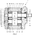
- FIG. 1 is a longitudinal section of a trained as a gear machine 1 hydraulic working machine according to one embodiment shown.
- This has a machine housing 2, which is closed by means of two housing cover 4 and 6.
- the Indian FIG. 1 right housing cover 6 of the gear machine 1 is penetrated by a first bearing shaft 8, on which a first gear 10 is disposed within the machine housing 2.
- the first gear 10 is connected to a second gear 12 via a helical gear 14 into engagement, wherein the gear 12 is rotatably mounted on a second bearing shaft 16.
- the first and second bearing shaft 8 and 16 are each guided in two plain bearings 18, 20 and 22, 24.
- the in the FIG. 1 Right sliding bearing 20, 24 are in a bearing body 26 and in the FIG. 1 left slide bearing 18, 22 received in a bearing body 28.
- the gears 10 and 12 are mounted in the axial direction in each case via a first axial surface 30 and 32 on the second bearing body 26 (right) and in each case via a second axial surface 34 and 36 respectively on the first bearing body 28 (left) slidably. Sliding surfaces between the gears 10, 12 and the bearing bodies 26, 28 may be provided to reduce the friction with a sliding coating, such as MoS 2 , graphite or PTFE.
- the bearing bodies 26 and 28 each have an end face 38 or 40 towards the housing covers 6 and 4, respectively.
- the housing cover 4, 6 are aligned by centering bolts 42 on the machine housing 2. Between the housing covers 4 and 6 and the machine housing 2, a housing seal 44 is arranged. Furthermore, an axial seal 46 is respectively introduced into the end faces 38 and 40 of the bearing bodies 26 and 28 for the separation of a high and a low pressure region of the gear machine 1. A shaft seal 48 seals the passage of the first bearing shaft 8 through in the FIG. 1 right housing cover 6 from.
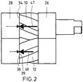
- FIG. 2 shows a simplified side view of a package of gears 10 and 12 and bearing bodies 26 and 28 for explaining the in the gear machine 1 from FIG. 1 operating hydraulic and mechanical forces.
- a force component of a hydraulic force acts in both gears 10, 12 in the same axial direction in the FIG. 2 to the left.
- acting on a driving gear that in the FIG. 2 the upper gear 10 is a mechanical force component of a mechanical force in the direction of action of the hydraulic force component and a driven gear, which in the FIG. 2 the lower gear 12 is a mechanical force component counter to the effective direction of the hydraulic force component.
- the hydraulic and mechanical force components result in both gears 10, 12 each having a resultant Axialkraftkomponente 47, 49 in the same direction (in FIG. 2 to the left), but with a different amount.
- gears 10 and 12 are respectively based on the axial surfaces 34 and 36 at the in the FIG. 2 left bearing body 28 from.
- the right bearing body 26 is not loaded by the force acting on the gears 10, 12 Axialkraftkomponenten.
- the gears are subjected to a counter force, resulting in the FIG. 2 marked with dashed arrows.
- FIG. 1 In the FIG. 1 are in the housing cover 4, two cylindrical pistons 70, 72 guided axially displaceable. These have a different diameter, with the in the FIG. 1 Upper piston has the larger diameter.
- the first piston 70 is approximately coaxial with in the FIG. 1 upper bearing shaft 8 and the second piston 72 is arranged approximately coaxially with the lower bearing shaft 16.
- the respective pistons 70 and 72 respectively extend in the direction of the axial force component 49 FIG. 2 pointing shaft end faces 78 and 80 of the bearing shafts 8 and 16 at.
- the pistons 70 and 72 are each acted upon via a further piston end face 82 and 84 with a hydraulic pressure and transmit this axially as a counter force on the bearing shafts 8 and 16.
- a pressure chamber 86 is provided, which of the housing cover 4 and another housing cover, not shown, is limited.
- the pressure field is connected to the high pressure of the gear machine 1 in fluid communication.
- the mechanical counterforce acting on the bearing shafts 8, 16 is predetermined via the piston diameter of the pistons 70, 72 and the height of the pressure in the pressure chamber 86. Since the in the FIG. 2 shown axial force components 47, 49 have a different size, the respective mechanical counterforce should also be different levels.
- the in FIG. 1 Upper piston 70 has, as already described, a larger diameter than the lower piston 72, whereby this has a larger pressure application surface and thus a higher pressure force on the piston 70 is transmitted as a counter force on the bearing shaft 8, if, as in the embodiment of Case is, an equal pressure on the piston 70, 72 acts. It would also be conceivable that the pistons 70, 72 have the same piston diameter and are also subjected to different pressures at a different pressure or at different piston diameters.
- the opposing forces are smaller than the axial forces 47, 49, so that with a resultant force, the gears 10, 12 are pressed against the bearing body 28 and this to the housing cover 4.
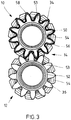
- FIG. 3 shows a plan view of the axial surfaces 34, 36 of the gears 10, 12 of a further embodiment, wherein the application of the gears 10, 12 is explained with an opposing hydraulic force in the following.
- the helical gearing 14 is clearly visible.
- the axial surfaces 34 and 36 of the gears 10 and 12 each have a pressure pocket 50 and 52, respectively.
- the pressure pockets 50, 52 each define with the first bearing body 28 FIG. 1 a pressure field which is in pressure fluid communication with the high pressure of the gear machine 1.
- the pressure pocket 52 of the gear 12 is formed as an annular groove 52 which is circumferentially introduced into the axial surface 36 between tooth end faces 53 of teeth 54 of the gear 12 and an outer circumferential surface of the bearing shaft 16.
- the pressure pocket 50 of the gear 10 has in addition to an annular groove corresponding to the pressure pocket 52 in the toothed end faces 53 inserted tooth pocket sections 56, whereby the pressure pocket 50 is thus introduced over a large area in the axial surface 34 and in its extent greater than the pressure pocket 52.
- the pressure pocket 50 is then bounded radially with a wall 58 running around the circumference of the gearwheel 14.
- the driving gear 10 has a larger axial force component 47, see FIG. 2
- a larger pressure application surface for the high pressure of the gear machine 1 is provided on the gear 10 so that corresponding to the higher Axialkraftkomponente 47 a higher counterforce on the gear 10 acts as on the gear 12th
- the counterforces applied to the gears 10, 12 via the pressure pockets 50, 52 are, as explained above, less than or equal to the respective axial force components 47, 49 FIG. 2 , As a result, the sliding friction between the gears 10, 12 and the bearing body 28 is reduced, whereby wear is minimized.
- the counterforce thus acts as Axialkraftkompensation on the gears 10, 12.
- the force resulting from the Axialkraftkomponenten 47, 49 and the opposing forces then serve for Axialspaltkompensation the sliding gap between the gears 10, 12 and the bearing body 28 (provided that the resultant force is not Zero).
- On the housing cover 4 facing end face of the bearing body 28 are no measures for the compensation of an axial gap between the gears 10, 12 and the bearing bodies 26, 28 necessary, so that here a very simple production is possible without much processing.
- the Indian FIG. 1 Right bearing body 26 is acted upon by no force resulting from the Axialkraftkomponenten and the counter forces.
- the sliding gap between the gears 10, 12 and the bearing body 26 is compensated for independently of the Axialkraftkomponenten and the opposing forces between the gears 10, 12 and the bearing body 28 in a conventional manner.
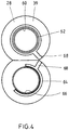
- FIG. 4 shows the gears 10, 12 off FIG. 1 facing end face 39 of an in FIG. 1 left spectacle-shaped bearing body 28 of a third embodiment.
- the bearing body 28 may, as in the FIG. 4 be formed in two parts. All around one in the FIG. 4 Upper bearing eye 60 is introduced into the end face 39 of the bearing body 28, a first annular pressure groove 62.
- a second pressure groove 64 is formed around the lower bearing eye 66 of the bearing body 28 substantially in the high pressure region of the gear machine 1, encompassing a partial circle.
- the pressure grooves 62, 64 are via radial grooves 68 to the high pressure of the gear machine 1 in fluid communication.
- the pressure groove 62 forms a first pressure field and the pressure groove 64 forms a second pressure field that is smaller than the first pressure field.
- the different sized axial forces 47, 49 thus counteract here also different sized counter forces.
- Axialspalt- and Axialkraftkompensation are independent of the type of bearing elements used and is therefore applicable to all, suitable for the axial sealing of gear machines components. The same applies to the type of gearing and its parameters. Such Axialspalt- and Axialkraftkompensation can be used both in external and internal gear machines.
- the gear machine can be used as a gear pump or motor.
- a gear machine with a housing for receiving two intermeshing gears. These are mounted slidably axially with axial surfaces between housed in the housing bearing bodies and radially, each with a bearing shaft accommodated in the bearing bodies.
- an axial force component of a force resulting from the operation of hydraulic and mechanical forces acts in the same axial direction on one gear in each case.
- the gear wheels and / or bearing shafts are each acted upon counter to the respective Axialkraftkomponente with a counter force which is equal to or less than / as the amount of the respective Axialkraftkomponente.
Claims (16)
- Machine à engrenages comprenant un boîtier (2) pour recevoir deux roues dentées (10, 12) s'engrenant l'une avec l'autre et notamment à denture oblique, qui sont supportées de manière à pouvoir coulisser axialement avec des surfaces axiales (30, 32, 34, 36) entre des corps de palier (26, 28) reçus dans le boîtier (2) et radialement avec un arbre de palier (8, 16) reçu dans les corps de palier (26, 28), une composante de force axiale (47, 49) d'une force résultant de forces hydrauliques et mécaniques se produisant pendant le fonctionnement de la machine à engrenages (1), agissant dans une direction axiale identique sur chaque roue dentée (10, 12), caractérisée en ce que les roues dentées (10, 12) et/ou les arbres de palier (8, 16) sont sollicités à l'encontre de la composante de force axiale respective (47, 49) à chaque fois avec une force conjuguée qui est dans chaque cas inférieure à la valeur absolue de la composante de force axiale respective (47, 49).
- Machine à engrenages selon la revendication 1, dans laquelle les roues dentées (10, 12) sont à denture oblique.
- Machine à engrenages selon la revendication 1 ou 2, dans laquelle le ou les premier (s) corps de palier (28) situé(s) dans la direction de la composante de force axiale active (47, 49) est/sont pressé(s) mécaniquement par le biais des roues dentées (10, 12) et/ou hydrauliquement par le biais d'une force de compression contre un couvercle de boîtier (4) du boîtier (2).
- Machine à engrenages selon la revendication 3, dans laquelle le ou les deuxième(s) corps de palier (26) est/sont sollicité(s) par une pression hydraulique au niveau d'une surface frontale (38) du côté du boîtier opposé aux roues dentées (10, 12).
- Machine à engrenages selon l'une quelconque des revendications précédentes, dans laquelle la force conjuguée est une force de compression et/ou une force mécanique.
- Machine à engrenages selon l'une quelconque des revendications précédentes, dans laquelle la force conjuguée agit par le biais d'un champ de compression entre au moins une roue dentée (10, 12) et le/les premier(s) corps de palier (28) sur l'au moins une roue dentée (10, 12).
- Machine à engrenages selon la revendication 6, dans laquelle une cavité de pression (50, 52) est réalisée dans la surface axiale (34, 36) tournée vers le/les premier(s) corps de palier (28) d'au moins une roue dentée (10, 12) pour limiter le champ de compression.
- Machine à engrenages selon la revendication 7, dans laquelle la surface axiale (34, 36) d'une roue dentée (10, 12) se compose de surfaces frontales dentées (53) et d'une surface annulaire et la cavité de pression (50, 52) comprend au moins une rainure annulaire (50, 52) réalisée dans la surface annulaire et s'étendant approximativement concentriquement autour d'un axe longitudinal de roue dentée de la roue dentée correspondante (10, 12).
- Machine à engrenages selon la revendication 8, dans laquelle la cavité de pression (50, 52) est élargie par des portions de cavités de dents (56) réalisées dans les surfaces frontales de dents (53) de la roue dentée (10).
- Machine à engrenages selon la revendication 9, dans laquelle la rainure annulaire (52) est réalisée dans la surface axiale (36) tournée vers le/les premier(s) corps de palier (28) de la roue dentée menée (12) et la cavité de pression (50) conjointement avec les portions de cavités de dents (56) est réalisée dans la surface axiale (34) de la roue dentée menante (10) tournée vers le/les premier(s) corps de palier (28).
- Machine à engrenages selon l'une quelconque des revendications 7 à 10, dans laquelle les cavités (50, 52, 56) sont en liaison fluidique sous pression avec une haute pression de la machine à engrenages (1).
- Machine à engrenages selon la revendication 6, dans laquelle une rainure de pression (62, 64) s'étendant au moins en partie autour d'un oeil de palier (60, 66) est réalisée dans la surface frontale (39) du/des premier(s) corps de palier (28) tournée vers les roues dentées (10, 12).
- Machine à engrenages selon la revendication 12, dans laquelle dans la surface frontale (39) du/des premier(s) corps de palier (28) tournée vers les roues dentées (10, 12), est réalisée une première rainure de pression (62) s'étendant une fois complètement et concentriquement autour d'un premier oeillet de palier (60) et une deuxième rainure de pression (64) venant en prise autour d'un cercle partiel est réalisée autour d'un deuxième oeil de palier (66), et les rainures de pression (62, 64) sont en liaison fluidique sous pression par le biais d'un raccord de fluide sous pression (68) avec la haute pression de la machine à engrenages (1).
- Machine à engrenages selon l'une quelconque des revendications 3 à 13, dans laquelle pour chaque arbre de palier respectif (8, 16), un piston (70, 72) est supporté de manière à glisser dans le couvercle de boîtier (4) du boîtier (2), approximativement coaxialement à l'axe longitudinal de la roue dentée en vue de la sollicitation par force des arbres de palier (8, 16), et dans laquelle le piston respectif (70, 72) s'applique avec une première surface frontale de piston (74, 76) contre une surface frontale d'arbre (78, 80) de l'arbre de palier (8, 16) tournée dans la direction de la composante de force axiale, et dans laquelle une deuxième surface frontale de piston (82, 84) du piston respectif (70, 72) est sollicitée en pression.
- Machine à engrenages selon la revendication 14, dans laquelle les deux pistons (70, 72) présentent, comparés l'un à l'autre, des surfaces sollicitées en pression de différentes tailles.
- Machine à engrenages selon la revendication 15, dans laquelle les deuxièmes surfaces frontales de piston (82, 84) des pistons (70, 72) sont connectées à la haute pression de la machine à engrenages (1).
Applications Claiming Priority (2)
| Application Number | Priority Date | Filing Date | Title |
|---|---|---|---|
| DE102009012853A DE102009012853A1 (de) | 2009-03-12 | 2009-03-12 | Hydraulische Zahnradmaschine |
| PCT/EP2010/001163 WO2010102722A2 (fr) | 2009-03-12 | 2010-02-25 | Machine hydraulique à engrenage |
Publications (2)
| Publication Number | Publication Date |
|---|---|
| EP2406497A2 EP2406497A2 (fr) | 2012-01-18 |
| EP2406497B1 true EP2406497B1 (fr) | 2017-01-11 |
Family
ID=42557916
Family Applications (1)
| Application Number | Title | Priority Date | Filing Date |
|---|---|---|---|
| EP10708110.1A Active EP2406497B1 (fr) | 2009-03-12 | 2010-02-25 | Machine hydraulique à engrenage |
Country Status (7)
| Country | Link |
|---|---|
| US (1) | US8979518B2 (fr) |
| EP (1) | EP2406497B1 (fr) |
| JP (1) | JP5535246B2 (fr) |
| CN (1) | CN102348897B (fr) |
| BR (1) | BRPI1009517B1 (fr) |
| DE (1) | DE102009012853A1 (fr) |
| WO (1) | WO2010102722A2 (fr) |
Families Citing this family (16)
| Publication number | Priority date | Publication date | Assignee | Title |
|---|---|---|---|---|
| DE102010055682A1 (de) | 2010-12-22 | 2012-06-28 | Robert Bosch Gmbh | Gehäuse einer Außenzahnradmaschine und Außenzahnradmaschine |
| ITTO20110912A1 (it) * | 2011-10-13 | 2013-04-14 | Vhit Spa | Pompa per vuoto rotativa |
| DE102012212829A1 (de) | 2012-07-23 | 2014-01-23 | Robert Bosch Gmbh | Zahnradmaschine mit Drehzahlmessung anhand der Druckpulsation |
| DE102012217115A1 (de) | 2012-09-24 | 2014-03-27 | Robert Bosch Gmbh | Zahnradmaschine mit von der Kreisform abweichendem Niederdruckanschluss |
| DE102012217400A1 (de) | 2012-09-26 | 2014-03-27 | Robert Bosch Gmbh | Zahnradmaschine mit einer Nut zur Aufnahme eines Einlaufgrates |
| DE102012219521A1 (de) | 2012-10-25 | 2014-04-30 | Robert Bosch Gmbh | Dichtungsanordnung mit Dichtschnur und Steg |
| DE102012220446A1 (de) | 2012-11-09 | 2014-05-15 | Robert Bosch Gmbh | Zahnradmaschine mit Druckentlastung des Quetschraums |
| DE102013202917A1 (de) | 2013-02-22 | 2014-08-28 | Robert Bosch Gmbh | Zahnradmaschine mit erhöhter Partikelrobustheit |
| WO2014141377A1 (fr) * | 2013-03-12 | 2014-09-18 | 株式会社 島津製作所 | Pompe ou moteur à roue dentée |
| ITAN20130102A1 (it) * | 2013-05-30 | 2014-12-01 | Marzocchi Pompe S P A | Pompa o motore idraulico ad ingranaggi a dentatura elicoidale con sistema idraulico per il bilanciamento di forze assiali. |
| US9366250B1 (en) | 2013-06-27 | 2016-06-14 | Sumitomo Precision Products Co., Ltd. | Hydraulic device |
| JP5761283B2 (ja) * | 2013-09-18 | 2015-08-12 | ダイキン工業株式会社 | ギヤポンプまたはギヤモータ |
| JP6075346B2 (ja) * | 2014-09-30 | 2017-02-08 | ダイキン工業株式会社 | 歯車ポンプ又は歯車モータ |
| US10584747B1 (en) * | 2018-12-03 | 2020-03-10 | Hamilton Sundstrand Corporation | Fuel pump bearing with non-concentric inner diameters |
| CN110594150B (zh) * | 2019-10-24 | 2021-02-23 | 山东大学 | 轴向和径向静压支承的螺旋齿双圆弧齿形液压齿轮泵 |
| CN111271217A (zh) * | 2020-04-04 | 2020-06-12 | 赵学清 | 一种利用液压系统回油压力发电的装置 |
Family Cites Families (11)
| Publication number | Priority date | Publication date | Assignee | Title |
|---|---|---|---|---|
| US3658452A (en) | 1969-11-18 | 1972-04-25 | Shimadzu Corp | Gear pump or motor |
| DE2315630A1 (de) * | 1973-03-29 | 1974-10-17 | Bosch Gmbh Robert | Zahnradmaschine |
| JPS542407Y1 (fr) * | 1973-07-12 | 1979-02-01 | ||
| AT355916B (de) * | 1976-07-13 | 1980-03-25 | Akzo Nv | Zahnradpumpe mit verminderter leistungsaufnahme zum foerdern viskoser fluessigkeiten |
| IT1124357B (it) * | 1979-11-23 | 1986-05-07 | Marzocchi Paolo & Adriano | Perfezionamenti particolarmente adatti per le pompe e per i motori idraulici ad ingranaggi di tipo elicoidale |
| US4781552A (en) | 1985-11-27 | 1988-11-01 | Jean Malfit | High pressure hydraulic generator receiver for power transmission |
| JPH09280181A (ja) * | 1996-04-09 | 1997-10-28 | Shimadzu Corp | ギヤポンプ |
| DE19924057A1 (de) | 1999-05-26 | 2000-11-30 | Bosch Gmbh Robert | Zahnradmaschine (Pumpe oder Motor) |
| ITBO20010540A1 (it) | 2001-09-07 | 2003-03-07 | Mario Antonio Morselli | Perfezionamenti in una pompa volumetrica rotativa |
| AU2003294889A1 (en) * | 2002-12-19 | 2004-07-14 | Haldex Hydraulics Gmbh | Gear-type machine comprising lateral axial plates |
| JP4829957B2 (ja) * | 2006-02-20 | 2011-12-07 | 島津メクテム株式会社 | 歯車ポンプ |
-
2009
- 2009-03-12 DE DE102009012853A patent/DE102009012853A1/de not_active Withdrawn
-
2010
- 2010-02-25 BR BRPI1009517-9A patent/BRPI1009517B1/pt active IP Right Grant
- 2010-02-25 EP EP10708110.1A patent/EP2406497B1/fr active Active
- 2010-02-25 US US13/256,053 patent/US8979518B2/en active Active
- 2010-02-25 WO PCT/EP2010/001163 patent/WO2010102722A2/fr active Application Filing
- 2010-02-25 CN CN201080011318.XA patent/CN102348897B/zh active Active
- 2010-02-25 JP JP2011553314A patent/JP5535246B2/ja active Active
Non-Patent Citations (1)
| Title |
|---|
| None * |
Also Published As
| Publication number | Publication date |
|---|---|
| EP2406497A2 (fr) | 2012-01-18 |
| DE102009012853A1 (de) | 2010-09-16 |
| BRPI1009517A2 (pt) | 2016-07-12 |
| US20120114514A1 (en) | 2012-05-10 |
| JP5535246B2 (ja) | 2014-07-02 |
| JP2012519798A (ja) | 2012-08-30 |
| CN102348897A (zh) | 2012-02-08 |
| CN102348897B (zh) | 2015-01-28 |
| US8979518B2 (en) | 2015-03-17 |
| BRPI1009517B1 (pt) | 2020-07-28 |
| WO2010102722A2 (fr) | 2010-09-16 |
| WO2010102722A3 (fr) | 2011-09-22 |
Similar Documents
| Publication | Publication Date | Title |
|---|---|---|
| EP2406497B1 (fr) | Machine hydraulique à engrenage | |
| DE1958225C3 (de) | Außeneingriffszahnradpumpe | |
| WO2010102723A2 (fr) | Machine hydraulique à engrenage | |
| WO2012034619A1 (fr) | Machine à pistons axiaux | |
| EP2561229A1 (fr) | Piston pour une machine à pistons radiaux | |
| DE2016097A1 (de) | Zahnradpumpe oder motor | |
| DE3342131C2 (fr) | ||
| DE102008064456B4 (de) | Servolenkungsvorrichtung | |
| DE1264958B (de) | Zahnradpumpe oder -motor | |
| WO2019243123A1 (fr) | Bague d'étanchéité à activité hydrodynamique et joint rotatif pourvu d'une telle bague d'étanchéité | |
| DE102008063500B4 (de) | Hydraulische Maschine | |
| EP2153075B1 (fr) | Palier | |
| EP2063126A2 (fr) | Machine hydraulique à roue dentée et procédé d'étanchéification d'une machine hydraulique à roue dentée | |
| EP2286088B1 (fr) | Pompe | |
| DE19810318B4 (de) | Hydraulikmaschine | |
| EP1461534B1 (fr) | Pompe | |
| EP1074740B1 (fr) | Machine hydrostatique à piston rotatif | |
| EP2409037B1 (fr) | Machine hydraulique à engrenage | |
| DE19906690B4 (de) | Dichtring | |
| EP2354551B1 (fr) | Machine hydraulique à roue dentée avec compensation de la force axiale. | |
| DE102009044725B3 (de) | Walze | |
| DE2944123C2 (de) | Spannungswellen-Getriebe | |
| EP4314560A1 (fr) | Machine à fluide à engrenages intérieurs et procédé de fabrication d'une machine à fluide à engrenages intérieurs | |
| DE102021115440A1 (de) | Rotationspumpe mit einer Axialschubbegrenzungseinrichtung | |
| DE102009012856A1 (de) | Hydraulische Zahnradmaschine |
Legal Events
| Date | Code | Title | Description |
|---|---|---|---|
| PUAI | Public reference made under article 153(3) epc to a published international application that has entered the european phase |
Free format text: ORIGINAL CODE: 0009012 |
|
| AK | Designated contracting states |
Kind code of ref document: A2 Designated state(s): AT BE BG CH CY CZ DE DK EE ES FI FR GB GR HR HU IE IS IT LI LT LU LV MC MK MT NL NO PL PT RO SE SI SK SM TR |
|
| AX | Request for extension of the european patent |
Extension state: AL BA RS |
|
| 17P | Request for examination filed |
Effective date: 20120322 |
|
| RBV | Designated contracting states (corrected) |
Designated state(s): AT BE BG CH CY CZ DE DK EE ES FI FR GB GR HR HU IE IS IT LI LT LU LV MC MK MT NL NO PL PT RO SE SI SK SM TR |
|
| DAX | Request for extension of the european patent (deleted) | ||
| GRAP | Despatch of communication of intention to grant a patent |
Free format text: ORIGINAL CODE: EPIDOSNIGR1 |
|
| INTG | Intention to grant announced |
Effective date: 20160922 |
|
| GRAS | Grant fee paid |
Free format text: ORIGINAL CODE: EPIDOSNIGR3 |
|
| GRAA | (expected) grant |
Free format text: ORIGINAL CODE: 0009210 |
|
| AK | Designated contracting states |
Kind code of ref document: B1 Designated state(s): AT BE BG CH CY CZ DE DK EE ES FI FR GB GR HR HU IE IS IT LI LT LU LV MC MK MT NL NO PL PT RO SE SI SK SM TR |
|
| REG | Reference to a national code |
Ref country code: GB Ref legal event code: FG4D Free format text: NOT ENGLISH |
|
| REG | Reference to a national code |
Ref country code: CH Ref legal event code: EP |
|
| REG | Reference to a national code |
Ref country code: AT Ref legal event code: REF Ref document number: 861562 Country of ref document: AT Kind code of ref document: T Effective date: 20170115 |
|
| REG | Reference to a national code |
Ref country code: IE Ref legal event code: FG4D Free format text: LANGUAGE OF EP DOCUMENT: GERMAN |
|
| REG | Reference to a national code |
Ref country code: DE Ref legal event code: R096 Ref document number: 502010013031 Country of ref document: DE |
|
| REG | Reference to a national code |
Ref country code: LT Ref legal event code: MG4D |
|
| REG | Reference to a national code |
Ref country code: NL Ref legal event code: MP Effective date: 20170111 |
|
| PG25 | Lapsed in a contracting state [announced via postgrant information from national office to epo] |
Ref country code: BE Free format text: LAPSE BECAUSE OF NON-PAYMENT OF DUE FEES Effective date: 20170228 |
|
| PG25 | Lapsed in a contracting state [announced via postgrant information from national office to epo] |
Ref country code: NL Free format text: LAPSE BECAUSE OF FAILURE TO SUBMIT A TRANSLATION OF THE DESCRIPTION OR TO PAY THE FEE WITHIN THE PRESCRIBED TIME-LIMIT Effective date: 20170111 |
|
| PG25 | Lapsed in a contracting state [announced via postgrant information from national office to epo] |
Ref country code: HR Free format text: LAPSE BECAUSE OF FAILURE TO SUBMIT A TRANSLATION OF THE DESCRIPTION OR TO PAY THE FEE WITHIN THE PRESCRIBED TIME-LIMIT Effective date: 20170111 Ref country code: GR Free format text: LAPSE BECAUSE OF FAILURE TO SUBMIT A TRANSLATION OF THE DESCRIPTION OR TO PAY THE FEE WITHIN THE PRESCRIBED TIME-LIMIT Effective date: 20170412 Ref country code: IS Free format text: LAPSE BECAUSE OF FAILURE TO SUBMIT A TRANSLATION OF THE DESCRIPTION OR TO PAY THE FEE WITHIN THE PRESCRIBED TIME-LIMIT Effective date: 20170511 Ref country code: LT Free format text: LAPSE BECAUSE OF FAILURE TO SUBMIT A TRANSLATION OF THE DESCRIPTION OR TO PAY THE FEE WITHIN THE PRESCRIBED TIME-LIMIT Effective date: 20170111 Ref country code: NO Free format text: LAPSE BECAUSE OF FAILURE TO SUBMIT A TRANSLATION OF THE DESCRIPTION OR TO PAY THE FEE WITHIN THE PRESCRIBED TIME-LIMIT Effective date: 20170411 Ref country code: FI Free format text: LAPSE BECAUSE OF FAILURE TO SUBMIT A TRANSLATION OF THE DESCRIPTION OR TO PAY THE FEE WITHIN THE PRESCRIBED TIME-LIMIT Effective date: 20170111 |
|
| PG25 | Lapsed in a contracting state [announced via postgrant information from national office to epo] |
Ref country code: LV Free format text: LAPSE BECAUSE OF FAILURE TO SUBMIT A TRANSLATION OF THE DESCRIPTION OR TO PAY THE FEE WITHIN THE PRESCRIBED TIME-LIMIT Effective date: 20170111 Ref country code: BG Free format text: LAPSE BECAUSE OF FAILURE TO SUBMIT A TRANSLATION OF THE DESCRIPTION OR TO PAY THE FEE WITHIN THE PRESCRIBED TIME-LIMIT Effective date: 20170411 Ref country code: ES Free format text: LAPSE BECAUSE OF FAILURE TO SUBMIT A TRANSLATION OF THE DESCRIPTION OR TO PAY THE FEE WITHIN THE PRESCRIBED TIME-LIMIT Effective date: 20170111 Ref country code: PL Free format text: LAPSE BECAUSE OF FAILURE TO SUBMIT A TRANSLATION OF THE DESCRIPTION OR TO PAY THE FEE WITHIN THE PRESCRIBED TIME-LIMIT Effective date: 20170111 Ref country code: PT Free format text: LAPSE BECAUSE OF FAILURE TO SUBMIT A TRANSLATION OF THE DESCRIPTION OR TO PAY THE FEE WITHIN THE PRESCRIBED TIME-LIMIT Effective date: 20170511 Ref country code: SE Free format text: LAPSE BECAUSE OF FAILURE TO SUBMIT A TRANSLATION OF THE DESCRIPTION OR TO PAY THE FEE WITHIN THE PRESCRIBED TIME-LIMIT Effective date: 20170111 |
|
| REG | Reference to a national code |
Ref country code: CH Ref legal event code: PL |
|
| REG | Reference to a national code |
Ref country code: DE Ref legal event code: R097 Ref document number: 502010013031 Country of ref document: DE |
|
| PG25 | Lapsed in a contracting state [announced via postgrant information from national office to epo] |
Ref country code: RO Free format text: LAPSE BECAUSE OF FAILURE TO SUBMIT A TRANSLATION OF THE DESCRIPTION OR TO PAY THE FEE WITHIN THE PRESCRIBED TIME-LIMIT Effective date: 20170111 Ref country code: LI Free format text: LAPSE BECAUSE OF NON-PAYMENT OF DUE FEES Effective date: 20170228 Ref country code: CH Free format text: LAPSE BECAUSE OF NON-PAYMENT OF DUE FEES Effective date: 20170228 Ref country code: EE Free format text: LAPSE BECAUSE OF FAILURE TO SUBMIT A TRANSLATION OF THE DESCRIPTION OR TO PAY THE FEE WITHIN THE PRESCRIBED TIME-LIMIT Effective date: 20170111 Ref country code: CZ Free format text: LAPSE BECAUSE OF FAILURE TO SUBMIT A TRANSLATION OF THE DESCRIPTION OR TO PAY THE FEE WITHIN THE PRESCRIBED TIME-LIMIT Effective date: 20170111 Ref country code: SK Free format text: LAPSE BECAUSE OF FAILURE TO SUBMIT A TRANSLATION OF THE DESCRIPTION OR TO PAY THE FEE WITHIN THE PRESCRIBED TIME-LIMIT Effective date: 20170111 |
|
| PLBE | No opposition filed within time limit |
Free format text: ORIGINAL CODE: 0009261 |
|
| STAA | Information on the status of an ep patent application or granted ep patent |
Free format text: STATUS: NO OPPOSITION FILED WITHIN TIME LIMIT |
|
| REG | Reference to a national code |
Ref country code: IE Ref legal event code: MM4A |
|
| PG25 | Lapsed in a contracting state [announced via postgrant information from national office to epo] |
Ref country code: MC Free format text: LAPSE BECAUSE OF FAILURE TO SUBMIT A TRANSLATION OF THE DESCRIPTION OR TO PAY THE FEE WITHIN THE PRESCRIBED TIME-LIMIT Effective date: 20170111 Ref country code: DK Free format text: LAPSE BECAUSE OF FAILURE TO SUBMIT A TRANSLATION OF THE DESCRIPTION OR TO PAY THE FEE WITHIN THE PRESCRIBED TIME-LIMIT Effective date: 20170111 Ref country code: SM Free format text: LAPSE BECAUSE OF FAILURE TO SUBMIT A TRANSLATION OF THE DESCRIPTION OR TO PAY THE FEE WITHIN THE PRESCRIBED TIME-LIMIT Effective date: 20170111 |
|
| REG | Reference to a national code |
Ref country code: FR Ref legal event code: ST Effective date: 20171031 |
|
| 26N | No opposition filed |
Effective date: 20171012 |
|
| GBPC | Gb: european patent ceased through non-payment of renewal fee |
Effective date: 20170411 |
|
| PG25 | Lapsed in a contracting state [announced via postgrant information from national office to epo] |
Ref country code: LU Free format text: LAPSE BECAUSE OF NON-PAYMENT OF DUE FEES Effective date: 20170225 |
|
| PG25 | Lapsed in a contracting state [announced via postgrant information from national office to epo] |
Ref country code: FR Free format text: LAPSE BECAUSE OF NON-PAYMENT OF DUE FEES Effective date: 20170313 |
|
| REG | Reference to a national code |
Ref country code: BE Ref legal event code: MM Effective date: 20170228 |
|
| PG25 | Lapsed in a contracting state [announced via postgrant information from national office to epo] |
Ref country code: IE Free format text: LAPSE BECAUSE OF NON-PAYMENT OF DUE FEES Effective date: 20170225 Ref country code: GB Free format text: LAPSE BECAUSE OF NON-PAYMENT OF DUE FEES Effective date: 20170411 Ref country code: SI Free format text: LAPSE BECAUSE OF FAILURE TO SUBMIT A TRANSLATION OF THE DESCRIPTION OR TO PAY THE FEE WITHIN THE PRESCRIBED TIME-LIMIT Effective date: 20170111 |
|
| REG | Reference to a national code |
Ref country code: AT Ref legal event code: MM01 Ref document number: 861562 Country of ref document: AT Kind code of ref document: T Effective date: 20170225 |
|
| PG25 | Lapsed in a contracting state [announced via postgrant information from national office to epo] |
Ref country code: AT Free format text: LAPSE BECAUSE OF NON-PAYMENT OF DUE FEES Effective date: 20170225 |
|
| PG25 | Lapsed in a contracting state [announced via postgrant information from national office to epo] |
Ref country code: MT Free format text: LAPSE BECAUSE OF FAILURE TO SUBMIT A TRANSLATION OF THE DESCRIPTION OR TO PAY THE FEE WITHIN THE PRESCRIBED TIME-LIMIT Effective date: 20170111 |
|
| PG25 | Lapsed in a contracting state [announced via postgrant information from national office to epo] |
Ref country code: HU Free format text: LAPSE BECAUSE OF FAILURE TO SUBMIT A TRANSLATION OF THE DESCRIPTION OR TO PAY THE FEE WITHIN THE PRESCRIBED TIME-LIMIT; INVALID AB INITIO Effective date: 20100225 |
|
| PG25 | Lapsed in a contracting state [announced via postgrant information from national office to epo] |
Ref country code: CY Free format text: LAPSE BECAUSE OF NON-PAYMENT OF DUE FEES Effective date: 20170111 |
|
| PG25 | Lapsed in a contracting state [announced via postgrant information from national office to epo] |
Ref country code: MK Free format text: LAPSE BECAUSE OF FAILURE TO SUBMIT A TRANSLATION OF THE DESCRIPTION OR TO PAY THE FEE WITHIN THE PRESCRIBED TIME-LIMIT Effective date: 20170111 |
|
| PG25 | Lapsed in a contracting state [announced via postgrant information from national office to epo] |
Ref country code: TR Free format text: LAPSE BECAUSE OF FAILURE TO SUBMIT A TRANSLATION OF THE DESCRIPTION OR TO PAY THE FEE WITHIN THE PRESCRIBED TIME-LIMIT Effective date: 20170111 |
|
| PGFP | Annual fee paid to national office [announced via postgrant information from national office to epo] |
Ref country code: IT Payment date: 20230228 Year of fee payment: 14 |
|
| PGFP | Annual fee paid to national office [announced via postgrant information from national office to epo] |
Ref country code: DE Payment date: 20230426 Year of fee payment: 14 |