EP2406497B1 - Hydraulic toothed wheel machine - Google Patents
Hydraulic toothed wheel machine Download PDFInfo
- Publication number
- EP2406497B1 EP2406497B1 EP10708110.1A EP10708110A EP2406497B1 EP 2406497 B1 EP2406497 B1 EP 2406497B1 EP 10708110 A EP10708110 A EP 10708110A EP 2406497 B1 EP2406497 B1 EP 2406497B1
- Authority
- EP
- European Patent Office
- Prior art keywords
- toothed wheel
- pressure
- bearing
- wheel machine
- machine according
- Prior art date
- Legal status (The legal status is an assumption and is not a legal conclusion. Google has not performed a legal analysis and makes no representation as to the accuracy of the status listed.)
- Active
Links
Images
Classifications
-
- F—MECHANICAL ENGINEERING; LIGHTING; HEATING; WEAPONS; BLASTING
- F04—POSITIVE - DISPLACEMENT MACHINES FOR LIQUIDS; PUMPS FOR LIQUIDS OR ELASTIC FLUIDS
- F04C—ROTARY-PISTON, OR OSCILLATING-PISTON, POSITIVE-DISPLACEMENT MACHINES FOR LIQUIDS; ROTARY-PISTON, OR OSCILLATING-PISTON, POSITIVE-DISPLACEMENT PUMPS
- F04C2/00—Rotary-piston machines or pumps
- F04C2/08—Rotary-piston machines or pumps of intermeshing-engagement type, i.e. with engagement of co-operating members similar to that of toothed gearing
- F04C2/12—Rotary-piston machines or pumps of intermeshing-engagement type, i.e. with engagement of co-operating members similar to that of toothed gearing of other than internal-axis type
- F04C2/14—Rotary-piston machines or pumps of intermeshing-engagement type, i.e. with engagement of co-operating members similar to that of toothed gearing of other than internal-axis type with toothed rotary pistons
- F04C2/18—Rotary-piston machines or pumps of intermeshing-engagement type, i.e. with engagement of co-operating members similar to that of toothed gearing of other than internal-axis type with toothed rotary pistons with similar tooth forms
-
- F—MECHANICAL ENGINEERING; LIGHTING; HEATING; WEAPONS; BLASTING
- F04—POSITIVE - DISPLACEMENT MACHINES FOR LIQUIDS; PUMPS FOR LIQUIDS OR ELASTIC FLUIDS
- F04C—ROTARY-PISTON, OR OSCILLATING-PISTON, POSITIVE-DISPLACEMENT MACHINES FOR LIQUIDS; ROTARY-PISTON, OR OSCILLATING-PISTON, POSITIVE-DISPLACEMENT PUMPS
- F04C15/00—Component parts, details or accessories of machines, pumps or pumping installations, not provided for in groups F04C2/00 - F04C14/00
- F04C15/0042—Systems for the equilibration of forces acting on the machines or pump
-
- F—MECHANICAL ENGINEERING; LIGHTING; HEATING; WEAPONS; BLASTING
- F04—POSITIVE - DISPLACEMENT MACHINES FOR LIQUIDS; PUMPS FOR LIQUIDS OR ELASTIC FLUIDS
- F04C—ROTARY-PISTON, OR OSCILLATING-PISTON, POSITIVE-DISPLACEMENT MACHINES FOR LIQUIDS; ROTARY-PISTON, OR OSCILLATING-PISTON, POSITIVE-DISPLACEMENT PUMPS
- F04C2240/00—Components
- F04C2240/50—Bearings
Definitions
- the invention relates to a hydraulic gear machine according to the preamble of patent claim 1.
- EP 1 291 526 A2 is a gear machine shown with a housing in which two intermeshing and mounted in bearing bushes or bearing bodies gears are arranged, wherein the housing is closed at each end face with a first and second housing cover.
- the helical gears are slidably mounted axially with two axial surfaces between the bearing bodies and radially in each case via a bearing shaft received in the bearing bodies.
- hydraulic and mechanical forces act on the gears in the same gear longitudinal axis in each case.
- the IT 1 124 357 is considered to be the closest prior art and discloses the features of the preamble of claim 1.
- the counterforce on the gears is applied via attacking on the bearing shafts piston.
- the pistons are slidably received approximately coaxially to the toothed wheel longitudinal axis in a between the first housing cover and the housing arranged intermediate cover and abut with a first piston end face on a pointing in the direction of the first housing cover shaft end face of the bearing shafts and are acted upon via a second piston end face in each case with pressure.
- the counterforce is applied to the first bearing body via a pressure field formed between the bearing body and the intermediate cover.
- a disadvantage of this solution is that the entire package of bearing bodies and gears is pressed onto the second housing cover of the gear machine, whereby the second housing cover and the housing are loaded very high and uneven. Furthermore, quite high wear occurs due to the compression of the gears and the bearing bodies between the axial surfaces of the gears and the bearing bodies.
- the object of the present invention is to provide a hydraulic gear machine with a low force application of machine elements, in particular housing covers and housing, and with minimal wear.
- a gear machine has a housing for receiving two intermeshing and in particular helical gears, which are mounted so as to slide axially with axial surfaces between bearing bodies received in the housing and radially in each case in a bearing shaft received in the bearing bodies.
- an axial force component of a force resulting from hydraulic and mechanical forces acts in a same axial direction on one gear each.
- the gears and / or bearing shafts are then counteracted against the respective Axialkraftkomponente with a counter force which is equal to or less than / as the amount of the respective Axialkraftkomponente.
- This solution has the advantage that the gears of the gear machine are each pressed with a reduced by the opposing force Axialkraftkomponente lying in the direction of the Axialkraftkomponente bearing body, which reduces sliding friction between the gears and the bearing body and the other not lying in the effective direction of the Axialkraftkomponente bearing body unloaded is.
- the reduced by the opposing forces Axialkraftkomponenten can then be provided as Axialspaltkompensation a sliding gap between lying in the effective direction of the force resulting bearing body and the gears.
- An axial gap compensation of a sliding gap between the not lying in the effective direction of the Axialkraftkomponente Bearing body and the gears can be used independently of the Axialkraftkomponenten.
- a load due to the axial force component on the housing cover and the housing can be reduced.
- the gears of the gear machine are helically toothed.
- the first bearing body lying in the direction of the acting Axialkraftkomponente is pressed mechanically via the gears and / or hydraulically via a pressure force on a housing cover of the housing.
- the reaction force acting on the gears and / or bearing shafts is a hydraulic pressure force and / or a mechanical force.
- the counterforce advantageously acts on at least one toothed wheel by means of a pressure field between at least one toothed wheel and the first bearing body.
- a pressure pocket can simply be introduced into the axial surface of the at least one gear wheel facing the first bearing body.
- the axial surface of a gear consists of tooth surfaces and an annular surface, wherein the pressure pockets is preferably one about a gear longitudinal axis of the corresponding gear approximately concentrically encircling, introduced into the annular surface annular groove.
- the annular groove can be extended by introduced into the tooth surfaces of the gear tooth pocket sections.
- the pockets with a high pressure of the gear machine in pressure medium connection are provided.
- a pressure field can be introduced and thereby be effected that the second bearing body is lightly pressed against the gears.
- a first pressure groove completely concentrically encircling a first bearing eye and a second pressure groove a pitch circle surrounding a second bearing eye introduced.
- the pressure grooves are then connected via a pressure medium connection with the high pressure of the gear machine in pressure medium connection.
- a piston in the housing cover of the housing mounted axially displaceable approximately coaxially with the gear longitudinal axis for applying force to the bearing shafts.
- the respective piston is arranged with a first piston end face to a pointing in the direction of the axial force component shaft end face of the bearing shaft in approximately fitting and acted upon by a second piston end face with pressure. With the piston, the mechanical counterforce on the bearing shafts can be easily applied.
- the second piston end faces are connected for pressurization with the high pressure of the gear machine.
- the pressure acting on the bearing shafts compressive force can be determined via the piston face diameter.
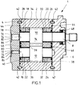
- FIG. 1 is a longitudinal section of a trained as a gear machine 1 hydraulic working machine according to one embodiment shown.
- This has a machine housing 2, which is closed by means of two housing cover 4 and 6.
- the Indian FIG. 1 right housing cover 6 of the gear machine 1 is penetrated by a first bearing shaft 8, on which a first gear 10 is disposed within the machine housing 2.
- the first gear 10 is connected to a second gear 12 via a helical gear 14 into engagement, wherein the gear 12 is rotatably mounted on a second bearing shaft 16.
- the first and second bearing shaft 8 and 16 are each guided in two plain bearings 18, 20 and 22, 24.
- the in the FIG. 1 Right sliding bearing 20, 24 are in a bearing body 26 and in the FIG. 1 left slide bearing 18, 22 received in a bearing body 28.
- the gears 10 and 12 are mounted in the axial direction in each case via a first axial surface 30 and 32 on the second bearing body 26 (right) and in each case via a second axial surface 34 and 36 respectively on the first bearing body 28 (left) slidably. Sliding surfaces between the gears 10, 12 and the bearing bodies 26, 28 may be provided to reduce the friction with a sliding coating, such as MoS 2 , graphite or PTFE.
- the bearing bodies 26 and 28 each have an end face 38 or 40 towards the housing covers 6 and 4, respectively.
- the housing cover 4, 6 are aligned by centering bolts 42 on the machine housing 2. Between the housing covers 4 and 6 and the machine housing 2, a housing seal 44 is arranged. Furthermore, an axial seal 46 is respectively introduced into the end faces 38 and 40 of the bearing bodies 26 and 28 for the separation of a high and a low pressure region of the gear machine 1. A shaft seal 48 seals the passage of the first bearing shaft 8 through in the FIG. 1 right housing cover 6 from.
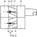
- FIG. 2 shows a simplified side view of a package of gears 10 and 12 and bearing bodies 26 and 28 for explaining the in the gear machine 1 from FIG. 1 operating hydraulic and mechanical forces.
- a force component of a hydraulic force acts in both gears 10, 12 in the same axial direction in the FIG. 2 to the left.
- acting on a driving gear that in the FIG. 2 the upper gear 10 is a mechanical force component of a mechanical force in the direction of action of the hydraulic force component and a driven gear, which in the FIG. 2 the lower gear 12 is a mechanical force component counter to the effective direction of the hydraulic force component.
- the hydraulic and mechanical force components result in both gears 10, 12 each having a resultant Axialkraftkomponente 47, 49 in the same direction (in FIG. 2 to the left), but with a different amount.
- gears 10 and 12 are respectively based on the axial surfaces 34 and 36 at the in the FIG. 2 left bearing body 28 from.
- the right bearing body 26 is not loaded by the force acting on the gears 10, 12 Axialkraftkomponenten.
- the gears are subjected to a counter force, resulting in the FIG. 2 marked with dashed arrows.
- FIG. 1 In the FIG. 1 are in the housing cover 4, two cylindrical pistons 70, 72 guided axially displaceable. These have a different diameter, with the in the FIG. 1 Upper piston has the larger diameter.
- the first piston 70 is approximately coaxial with in the FIG. 1 upper bearing shaft 8 and the second piston 72 is arranged approximately coaxially with the lower bearing shaft 16.
- the respective pistons 70 and 72 respectively extend in the direction of the axial force component 49 FIG. 2 pointing shaft end faces 78 and 80 of the bearing shafts 8 and 16 at.
- the pistons 70 and 72 are each acted upon via a further piston end face 82 and 84 with a hydraulic pressure and transmit this axially as a counter force on the bearing shafts 8 and 16.
- a pressure chamber 86 is provided, which of the housing cover 4 and another housing cover, not shown, is limited.
- the pressure field is connected to the high pressure of the gear machine 1 in fluid communication.
- the mechanical counterforce acting on the bearing shafts 8, 16 is predetermined via the piston diameter of the pistons 70, 72 and the height of the pressure in the pressure chamber 86. Since the in the FIG. 2 shown axial force components 47, 49 have a different size, the respective mechanical counterforce should also be different levels.
- the in FIG. 1 Upper piston 70 has, as already described, a larger diameter than the lower piston 72, whereby this has a larger pressure application surface and thus a higher pressure force on the piston 70 is transmitted as a counter force on the bearing shaft 8, if, as in the embodiment of Case is, an equal pressure on the piston 70, 72 acts. It would also be conceivable that the pistons 70, 72 have the same piston diameter and are also subjected to different pressures at a different pressure or at different piston diameters.
- the opposing forces are smaller than the axial forces 47, 49, so that with a resultant force, the gears 10, 12 are pressed against the bearing body 28 and this to the housing cover 4.
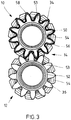
- FIG. 3 shows a plan view of the axial surfaces 34, 36 of the gears 10, 12 of a further embodiment, wherein the application of the gears 10, 12 is explained with an opposing hydraulic force in the following.
- the helical gearing 14 is clearly visible.
- the axial surfaces 34 and 36 of the gears 10 and 12 each have a pressure pocket 50 and 52, respectively.
- the pressure pockets 50, 52 each define with the first bearing body 28 FIG. 1 a pressure field which is in pressure fluid communication with the high pressure of the gear machine 1.
- the pressure pocket 52 of the gear 12 is formed as an annular groove 52 which is circumferentially introduced into the axial surface 36 between tooth end faces 53 of teeth 54 of the gear 12 and an outer circumferential surface of the bearing shaft 16.
- the pressure pocket 50 of the gear 10 has in addition to an annular groove corresponding to the pressure pocket 52 in the toothed end faces 53 inserted tooth pocket sections 56, whereby the pressure pocket 50 is thus introduced over a large area in the axial surface 34 and in its extent greater than the pressure pocket 52.
- the pressure pocket 50 is then bounded radially with a wall 58 running around the circumference of the gearwheel 14.
- the driving gear 10 has a larger axial force component 47, see FIG. 2
- a larger pressure application surface for the high pressure of the gear machine 1 is provided on the gear 10 so that corresponding to the higher Axialkraftkomponente 47 a higher counterforce on the gear 10 acts as on the gear 12th
- the counterforces applied to the gears 10, 12 via the pressure pockets 50, 52 are, as explained above, less than or equal to the respective axial force components 47, 49 FIG. 2 , As a result, the sliding friction between the gears 10, 12 and the bearing body 28 is reduced, whereby wear is minimized.
- the counterforce thus acts as Axialkraftkompensation on the gears 10, 12.
- the force resulting from the Axialkraftkomponenten 47, 49 and the opposing forces then serve for Axialspaltkompensation the sliding gap between the gears 10, 12 and the bearing body 28 (provided that the resultant force is not Zero).
- On the housing cover 4 facing end face of the bearing body 28 are no measures for the compensation of an axial gap between the gears 10, 12 and the bearing bodies 26, 28 necessary, so that here a very simple production is possible without much processing.
- the Indian FIG. 1 Right bearing body 26 is acted upon by no force resulting from the Axialkraftkomponenten and the counter forces.
- the sliding gap between the gears 10, 12 and the bearing body 26 is compensated for independently of the Axialkraftkomponenten and the opposing forces between the gears 10, 12 and the bearing body 28 in a conventional manner.
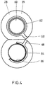
- FIG. 4 shows the gears 10, 12 off FIG. 1 facing end face 39 of an in FIG. 1 left spectacle-shaped bearing body 28 of a third embodiment.
- the bearing body 28 may, as in the FIG. 4 be formed in two parts. All around one in the FIG. 4 Upper bearing eye 60 is introduced into the end face 39 of the bearing body 28, a first annular pressure groove 62.
- a second pressure groove 64 is formed around the lower bearing eye 66 of the bearing body 28 substantially in the high pressure region of the gear machine 1, encompassing a partial circle.
- the pressure grooves 62, 64 are via radial grooves 68 to the high pressure of the gear machine 1 in fluid communication.
- the pressure groove 62 forms a first pressure field and the pressure groove 64 forms a second pressure field that is smaller than the first pressure field.
- the different sized axial forces 47, 49 thus counteract here also different sized counter forces.
- Axialspalt- and Axialkraftkompensation are independent of the type of bearing elements used and is therefore applicable to all, suitable for the axial sealing of gear machines components. The same applies to the type of gearing and its parameters. Such Axialspalt- and Axialkraftkompensation can be used both in external and internal gear machines.
- the gear machine can be used as a gear pump or motor.
- a gear machine with a housing for receiving two intermeshing gears. These are mounted slidably axially with axial surfaces between housed in the housing bearing bodies and radially, each with a bearing shaft accommodated in the bearing bodies.
- an axial force component of a force resulting from the operation of hydraulic and mechanical forces acts in the same axial direction on one gear in each case.
- the gear wheels and / or bearing shafts are each acted upon counter to the respective Axialkraftkomponente with a counter force which is equal to or less than / as the amount of the respective Axialkraftkomponente.
Description
Die Erfindung betrifft eine hydraulische Zahnradmaschine gemäß dem Oberbegriff des Patentanspruchs 1.The invention relates to a hydraulic gear machine according to the preamble of
In der
Die
Die Gegenkraft auf die Zahnräder wird über an den Lagerwellen angreifende Kolben aufgebracht. Die Kolben sind dabei etwa koaxial zur Zahnradlängsachse in einem zwischen dem ersten Gehäusedeckel und dem Gehäuse angeordneten Zwischendeckel gleitend aufgenommen und liegen mit einer ersten Kolbenstirnfläche an einer in Richtung des ersten Gehäusedeckels weisenden Wellenstirnfläche der Lagerwellen an und werden über eine zweite Kolbenstirnfläche jeweils mit Druck beaufschlagt. Auf den ersten Lagerkörper wird die Gegenkraft über ein zwischen dem Lagerkörper und dem Zwischendeckel ausgebildetes Druckfeld aufgebracht.The counterforce on the gears is applied via attacking on the bearing shafts piston. The pistons are slidably received approximately coaxially to the toothed wheel longitudinal axis in a between the first housing cover and the housing arranged intermediate cover and abut with a first piston end face on a pointing in the direction of the first housing cover shaft end face of the bearing shafts and are acted upon via a second piston end face in each case with pressure. The counterforce is applied to the first bearing body via a pressure field formed between the bearing body and the intermediate cover.
Nachteilig bei dieser Lösung ist, dass das gesamte Paket aus Lagerkörpern und Zahnrädern auf den zweiten Gehäusedeckel der Zahnradmaschine gepresst ist, wodurch der zweite Gehäusedeckel und das Gehäuse sehr hoch und ungleichmäßig belastet sind. Des Weiteren tritt ein recht hoher Verschleiß durch das Zusammenpressen der Zahnräder und der Lagerkörper zwischen den Axialflächen der Zahnräder und den Lagerkörpern auf.A disadvantage of this solution is that the entire package of bearing bodies and gears is pressed onto the second housing cover of the gear machine, whereby the second housing cover and the housing are loaded very high and uneven. Furthermore, quite high wear occurs due to the compression of the gears and the bearing bodies between the axial surfaces of the gears and the bearing bodies.
Die Aufgabe der vorliegenden Erfindung ist es, eine hydraulische Zahnradmaschine mit einer geringen Kraftbeaufschlagung von Maschinenelementen, insbesondere Gehäusedeckeln und Gehäuse, und mit minimalen Verschleiß zu schaffen.The object of the present invention is to provide a hydraulic gear machine with a low force application of machine elements, in particular housing covers and housing, and with minimal wear.
Diese Aufgabe wird gelöst durch eine hydraulische Zahnradmaschine gemäß den Merkmalen des Patentanspruchs 1.This object is achieved by a hydraulic gear machine according to the features of
Erfindungsgemäß hat eine Zahnradmaschine ein Gehäuse zum Aufnehmen zweier miteinander kämmender und insbesondere schrägverzahnter Zahnräder, die axial mit Axialflächen zwischen im Gehäuse aufgenommenen Lagerkörpern und radial mit jeweils in einer in den Lagerkörpern aufgenommenen Lagerwelle gleitend gelagert sind. Im Betrieb der Zahnradmaschine wirkt eine Axialkraftkomponente einer aus hydraulischen und mechanischen Kräften resultierenden Kraft in eine gleiche Axialrichtung auf jeweils ein Zahnrad. Die Zahnräder und/oder Lagerwellen sind dann entgegen der jeweiligen Axialkraftkomponente mit einer Gegenkraft beaufschlagt, die gleich oder kleiner wie/ als der Betrag der jeweiligen Axialkraftkomponente ist.According to the invention, a gear machine has a housing for receiving two intermeshing and in particular helical gears, which are mounted so as to slide axially with axial surfaces between bearing bodies received in the housing and radially in each case in a bearing shaft received in the bearing bodies. During operation of the gear machine, an axial force component of a force resulting from hydraulic and mechanical forces acts in a same axial direction on one gear each. The gears and / or bearing shafts are then counteracted against the respective Axialkraftkomponente with a counter force which is equal to or less than / as the amount of the respective Axialkraftkomponente.
Diese Lösung hat den Vorteil, dass die Zahnräder der Zahnradmaschine jeweils mit einer durch die Gegenkraft verminderten Axialkraftkomponente auf den in Wirkrichtung der Axialkraftkomponente liegende Lagerkörper gedrückt sind, wodurch Gleitreibung zwischen den Zahnrädern und dem Lagerkörper verringert und der andere nicht in Wirkrichtung der Axialkraftkomponente liegende Lagerkörper unbelastet ist. Die durch die Gegenkräfte verminderten Axialkraftkomponenten können dann als Axialspaltkompensation eines Gleitspalts zwischen dem in Wirkrichtung der Kraftresultierenden liegenden Lagerkörper und den Zahnrädern vorgesehen sein. Eine Axialspaltkompensation eines Gleitspalts zwischen dem nicht in Wirkrichtung der Axialkraftkomponente liegende Lagerkörper und den Zahnrädern kann unabhängig von den Axialkraftkomponenten eingesetzt werden. Durch die Gegenkraft kann des Weiteren eine Belastung aufgrund der Axialkraftkomponente auf Gehäusedeckel und das Gehäuse gesenkt werden.This solution has the advantage that the gears of the gear machine are each pressed with a reduced by the opposing force Axialkraftkomponente lying in the direction of the Axialkraftkomponente bearing body, which reduces sliding friction between the gears and the bearing body and the other not lying in the effective direction of the Axialkraftkomponente bearing body unloaded is. The reduced by the opposing forces Axialkraftkomponenten can then be provided as Axialspaltkompensation a sliding gap between lying in the effective direction of the force resulting bearing body and the gears. An axial gap compensation of a sliding gap between the not lying in the effective direction of the Axialkraftkomponente Bearing body and the gears can be used independently of the Axialkraftkomponenten. Furthermore, due to the counterforce, a load due to the axial force component on the housing cover and the housing can be reduced.
Vorzugsweise sind die Zahnräder der Zahnradmaschine schräg verzahnt.Preferably, the gears of the gear machine are helically toothed.
Von Vorteil wird der in Richtung der wirkenden Axialkraftkomponente liegende erste Lagerkörper mechanisch über die Zahnräder und/oder hydraulisch über eine Druckkraft auf einen Gehäusedeckel des Gehäuses gedrückt.Advantageously, the first bearing body lying in the direction of the acting Axialkraftkomponente is pressed mechanically via the gears and / or hydraulically via a pressure force on a housing cover of the housing.
Für eine leichte Anlage des zweiten Lagerkörpers an den Zahnrädern wird der Lagerkörper an einer den Zahnrädern abgewandten Stirnfläche mit einem hydraulischen Druck beaufschlagt.For easy installation of the second bearing body on the gears of the bearing body is applied to a remote from the gears end face with a hydraulic pressure.
Bevorzugterweise ist die auf die Zahnräder und/oder Lagerwellen wirkende Gegenkraft eine hydraulische Druckkraft und/oder eine mechanische Kraft.Preferably, the reaction force acting on the gears and / or bearing shafts is a hydraulic pressure force and / or a mechanical force.
Vorteilhaft wirkt die Gegenkraft durch ein Druckfeld zwischen zumindest einem Zahnrad und dem ersten Lagerkörper auf zumindest eine Zahnrad. Zum Abgrenzen des Druckfeldes kann einfach eine Drucktasche in die zum erste Lagerkörper zuweisende Axialfläche des zumindest einen Zahnrads eingebracht sein.The counterforce advantageously acts on at least one toothed wheel by means of a pressure field between at least one toothed wheel and the first bearing body. To delineate the pressure field, a pressure pocket can simply be introduced into the axial surface of the at least one gear wheel facing the first bearing body.
Die Axialfläche eines Zahnrads besteht aus Zahnflächen und einer Ringfläche, wobei die Drucktaschen vorzugsweise eine um eine Zahnradlängsachse des entsprechenden Zahnrads etwa konzentrisch umlaufende, in die Ringfläche eingebrachte Ringnut ist. Zur Vergrößerung des Druckfeldes und somit der Angriffsfläche des hydraulischen Drucks kann die Ringnut um in die Zahnflächen des Zahnrads eingebrachte Zahntaschenabschnitte erweitert sein.The axial surface of a gear consists of tooth surfaces and an annular surface, wherein the pressure pockets is preferably one about a gear longitudinal axis of the corresponding gear approximately concentrically encircling, introduced into the annular surface annular groove. To increase the pressure field and thus the attack surface of the hydraulic pressure, the annular groove can be extended by introduced into the tooth surfaces of the gear tooth pocket sections.
In weiterer Ausgestaltung der Erfindung ist in die zum ersten Lagerkörper zuweisende Axialfläche des antreibenden Zahnrads die Ringnut und die zum ersten Lagerkörper zuweisende Axialfläche des treibenden Zahnrads die Ringnut zusammen mit den Zahntaschenabschnitte eingebracht, da die Axialkraftkomponente beim treibenden Zahnrad größer als beim getriebenen ist.In a further embodiment of the invention is in the first bearing body assigning the axial surface of the driving gear, the annular groove and the first bearing body assigning axial surface of the driving gear, the annular groove together with the Zahntaschenabschnitte introduced because the Axialkraftkomponente is larger in the driving gear than the driven.
Zweckmäßig sind die Taschen mit einem Hochdruck der Zahnradmaschine in Druckmittelverbindung.Suitably, the pockets with a high pressure of the gear machine in pressure medium connection.
In die den Zahnrädern abgewandten Stirnfläche des zweiten Lagerkörpers kann ein Druckfeld eingebracht sein und dadurch bewirkt werden, dass der zweite Lagerkörper leicht gegen die Zahnräder gedrückt wird.In the gear wheels facing away from the end face of the second bearing body, a pressure field can be introduced and thereby be effected that the second bearing body is lightly pressed against the gears.
Mit Vorteil wird in die den Zahnrädern abgewandten Stirnfläche des zweiten Lagerkörpers eine erste Drucknut vollständig konzentrisch umlaufend um ein erstes Lagerauge und eine zweite Drucknut einen Teilkreis umgreifend um ein zweites Lagerauge eingebracht. Die Drucknuten sind dann über einen Druckmittelanschluss mit dem Hochdruck der Zahnradmaschine in Druckmittelverbindung.Advantageously, in the gear wheels facing away from the end face of the second bearing body, a first pressure groove completely concentrically encircling a first bearing eye and a second pressure groove a pitch circle surrounding a second bearing eye introduced. The pressure grooves are then connected via a pressure medium connection with the high pressure of the gear machine in pressure medium connection.
Bei einer bevorzugten Ausgestaltung der Zahnradmaschine ist jeweils zu einer Lagerwelle ein Kolben in dem Gehäusedeckel des Gehäuses, etwa koaxial zur Zahnradlängsachse zur Kraftbeaufschlagung der Lagerwellen axial verschiebbar gelagert. Der jeweilige Kolben ist mit einer ersten Kolbenstirnfläche an eine in Richtung der Axialkraftkomponente weisenden Wellenstirnfläche der Lagerwelle in etwa anliegend angeordnet und über eine zweite Kolbenstirnfläche mit Druck beaufschlagt. Mit den Kolben ist die mechanische Gegenkraft auf die Lagerwellen einfach aufbringbar.In a preferred embodiment of the gear machine is in each case to a bearing shaft, a piston in the housing cover of the housing, mounted axially displaceable approximately coaxially with the gear longitudinal axis for applying force to the bearing shafts. The respective piston is arranged with a first piston end face to a pointing in the direction of the axial force component shaft end face of the bearing shaft in approximately fitting and acted upon by a second piston end face with pressure. With the piston, the mechanical counterforce on the bearing shafts can be easily applied.
Die zweiten Kolbenstirnflächen sind zur Druckbeaufschlagung mit dem Hochdruck der Zahnradmaschine verbunden. Über den Kolbenstirnflächendurchmesser ist die auf die Lagerwellen wirkende Druckkraft bestimmbar.The second piston end faces are connected for pressurization with the high pressure of the gear machine. The pressure acting on the bearing shafts compressive force can be determined via the piston face diameter.
Sonstige vorteilhafte Weiterbildungen der Erfindung sind Gegenstand weiterer Unteransprüche.Other advantageous developments of the invention are the subject of further subclaims.
Im Folgenden werden bevorzugte Ausführungsbeispiele einer Erfindung anhand schematischer Zeichnungen näher erläutert. Es zeigen:
-
Figur 1 -
Figur 2Figur 1 -
Figur 3 eine Draufsicht auf die Zahnräder eines zweiten Ausführungsbeispiels und -
Figur 4
-
FIG. 1 in a longitudinal section a simplified representation of a gear machine according to an embodiment; -
FIG. 2 in a side view of a simplified representation of a package of bearing bodies and gears of the gear machineFIG. 1 ; -
FIG. 3 a plan view of the gears of a second embodiment and -
FIG. 4 a plan view of a bearing body of a third embodiment of the gears.
In
Die Gehäusedeckel 4, 6 sind über Zentrierbolzen 42 an dem Maschinengehäuse 2 ausgerichtet. Zwischen den Gehäusedeckeln 4 und 6 und dem Maschinengehäuse 2 ist eine Gehäusedichtung 44 angeordnet. Des Weiteren ist eine Axialdichtung 46 jeweils in die Stirnflächen 38 und 40 der Lagerkörper 26 bzw. 28 zur Trennung eines Hoch- von einem Niederdruckbereich der Zahnradmaschine 1 eingebracht. Ein Wellendichtring 48 dichtet den Durchgriff der ersten Lagerwelle 8 durch den in der
Im Betrieb der Zahnradmaschine 1 treten hydraulische und mechanische Kräfte auf, was schematisch in der folgenden
Die mit Axialkraftkomponenten 47, 49 beaufschlagten Zahnräder 10 und 12 stützen sich jeweils mit den Axialflächen 34 bzw. 36 an dem in der
In der
Die auf die Lagerwellen 8, 16 wirkende mechanische Gegenkraft ist über den Kolbendurchmesser der Kolben 70, 72 und die Höhe des Drucks im Druckraum 86 vorgegeben. Da die in der
Durch die auf die Zahnräder 10, 12 über die Lagerwellen 8, 16 beaufschlagte mechanische Gegenkraft wird der Rest der Axialkraft unter Umgehung des Lagerkörpers 28 in das Gehäuse 2 eingeleitet.By acting on the
Beim treibenden Zahnrad 10 wirkt eine größere Axialkraftkomponente 47, siehe
Die auf die Zahnräder 10, 12 über die Drucktaschen 50 bzw. 52 aufgebrachten Gegenkräfte sind wie vorstehend erläutert kleiner oder gleich wie die jeweilige Axialkraftkomponenten 47, 49 aus
Der in der
Bei den Ausführungsbeispielen nach den
Die Wirkungsweise der vorstehend erläuterten Axialspalt- und Axialkraftkompensation ist dabei unabhängig von der Bauart der eingesetzten Lagerelemente und ist daher bei allen, für die axiale Abdichtung von Zahnradmaschinen geeigneten Bauelementen anwendbar. Gleiches gilt auch für die Art der Verzahnung und deren Parameter. Eine derartige Axialspalt- und Axialkraftkompensation ist sowohl in Außen- als auch in Innenzahnradmaschinen einsetzbar.The mode of action of the above-described Axialspalt- and Axialkraftkompensation is independent of the type of bearing elements used and is therefore applicable to all, suitable for the axial sealing of gear machines components. The same applies to the type of gearing and its parameters. Such Axialspalt- and Axialkraftkompensation can be used both in external and internal gear machines.
Die Zahnradmaschine ist als Zahnradpumpe oder -motor einsetzbar.The gear machine can be used as a gear pump or motor.
Offenbart ist eine Zahnradmaschine mit einem Gehäuse zum Aufnehmen zweier miteinander kämmender Zahnräder. Diese sind axial mit Axialflächen zwischen im Gehäuse aufgenommenen Lagerkörpern und radial mit jeweils einer in den Lagerkörpern aufgenommenen Lagerwelle gleitend gelagert. Im Betrieb der Zahnradmaschine wirken auf jeweils ein Zahnrad eine Axialkraftkomponente einer aus im Betrieb auftretenden hydraulischen und mechanischen Kräften resultierenden Kraft in gleiche Axialrichtung. Die Zahnräder und/ oder Lagerwellen sind entgegen der jeweiligen Axialkraftkomponente jeweils mit einer Gegenkraft beaufschlagt, die jeweils gleich oder kleiner wie/ als der Betrag der jeweiligen Axialkraftkomponente ist.Disclosed is a gear machine with a housing for receiving two intermeshing gears. These are mounted slidably axially with axial surfaces between housed in the housing bearing bodies and radially, each with a bearing shaft accommodated in the bearing bodies. During operation of the gear machine, an axial force component of a force resulting from the operation of hydraulic and mechanical forces acts in the same axial direction on one gear in each case. The gear wheels and / or bearing shafts are each acted upon counter to the respective Axialkraftkomponente with a counter force which is equal to or less than / as the amount of the respective Axialkraftkomponente.
Claims (16)
- Toothed wheel machine having a housing (2) for accommodating two intermeshing toothed wheels (10, 12), in particular helically toothed wheels, which are supported in a sliding manner axially by axial surfaces (30, 32, 34, 36) between bearing bodies (26, 28) accommodated in the housing (2) and radially by respective bearing shafts (8, 16) accommodated in the bearing bodies (26, 28), in which an axial force component (47, 49) of a force resulting from hydraulic and mechanical forces arising during operation of the toothed wheel machine (1) acts on each toothed wheel (10, 12) in the same axial direction, characterized in that a counter-force against the respective axial force component (47, 49) is applied to the toothed wheels (10, 12) and/or bearing shafts (8, 16), the magnitude of each counter-force being less than that of the respective axial force component (47, 49).
- Toothed wheel machine according to Claim 1, wherein the toothed wheels (10, 12) are helically toothed.
- Toothed wheel machine according to Claim 1 or 2, wherein the first bearing body or bodies (28), which lies or lie in the direction of the effective axial force component (47, 49), is/are pressed against a housing cover (4) of the housing (2) mechanically by way of the toothed wheels (10, 12) and/or hydraulically by way of a pressure force.
- Toothed wheel machine according to Claim 3, wherein a hydraulic pressure is applied to the second bearing body or bodies (26) at an end face (38) on the housing side, said face facing away from the toothed wheels (10, 12).
- Toothed wheel machine according to one of the preceding claims, wherein the counter-force is a pressure force and/or a mechanical force.
- Toothed wheel machine according to one of the preceding claims, wherein the counter-force acts on the at least one toothed wheel (10, 12) by means of a pressure field between at least one toothed wheel (10, 12) and the first bearing body or bodies (28).
- Toothed wheel machine according to Claim 6, wherein a pressure pocket (50, 52) is introduced into that axial surface (34, 36) of at least one toothed wheel (10, 12) which faces the first bearing body (bearing bodies) (28) in order to delimit the pressure field.
- Toothed wheel machine according to Claim 7, wherein the axial surface (34, 36) of one toothed wheel (10, 12) consists of tooth end faces (53) and of an annular surface, and the pressure pocket (50, 52) comprises at least one annular groove (50, 52) introduced into the annular surface and running approximately concentrically around a longitudinal axis of the corresponding toothed wheel (10, 12).
- Toothed wheel machine according to Claim 8, wherein the pressure pocket (50, 52) is enlarged by tooth pocket sections (56) introduced into the tooth end faces (53) of toothed wheel (10).
- Toothed wheel machine according to Claim 9, wherein the annular groove (52) is introduced into that axial surface (36) of the driven toothed wheel (12) which faces the first bearing body (bearing bodies) (28), and the pressure pocket (50) together with the tooth pocket sections (56) is introduced into that axial surface (34) of the driving toothed wheel (10) which faces the first bearing body (bearing bodies) (28).
- Toothed wheel machine according to one of Claims 7 to 10, wherein the pockets (50, 52, 56) are in pressure-medium communication with a high pressure of the toothed wheel machine (1).
- Toothed wheel machine according to Claim 6, wherein a pressure groove (62, 64) running at least partially around a bearing eye (60, 66) is introduced into that end face (39) of the first bearing body (bearing bodies) (28) which faces the toothed wheels (10, 12).
- Toothed wheel machine according to Claim 12, wherein that end face (39) of the first bearing body (bearing bodies) (28) which faces the toothed wheels (10, 12) has introduced into it a first pressure groove (62), running once concentrically all the way round a first bearing eye (60), and a second pressure groove (64), spanning a partial circle around a second bearing eye (66), and wherein the pressure grooves (62, 64) are in pressure-medium communication with the high pressure of the toothed wheel machine (1) via a pressure-medium port (68).
- Toothed wheel machine according to one of Claims 3 to 13, wherein, for each bearing shaft (8, 16), there is a piston (70, 72) supported in a sliding manner in the housing cover (4) of the housing (2), approximately coaxially with respect to the toothed wheel longitudinal axis, for applying force to the bearing shafts (8, 16), and wherein the respective piston (70, 72) rests by means of a first piston end face (74, 76) against a shaft end face (78, 80) of the bearing shaft (8, 16) which faces in the direction of the axial force component, and wherein pressure is applied to a second piston end face (82, 84) of the respective piston (70, 72).
- Toothed wheel machine according to Claim 14, wherein the two pistons (70, 72) have pressure application areas of different sizes in comparison with one another.
- Toothed wheel machine according to Claim 15, wherein the second piston end faces (82, 84) of the pistons (70, 72) are connected to the high pressure of the toothed wheel machine (1).
Applications Claiming Priority (2)
| Application Number | Priority Date | Filing Date | Title |
|---|---|---|---|
| DE102009012853A DE102009012853A1 (en) | 2009-03-12 | 2009-03-12 | Hydraulic gear machine |
| PCT/EP2010/001163 WO2010102722A2 (en) | 2009-03-12 | 2010-02-25 | Hydraulic toothed wheel machine |
Publications (2)
| Publication Number | Publication Date |
|---|---|
| EP2406497A2 EP2406497A2 (en) | 2012-01-18 |
| EP2406497B1 true EP2406497B1 (en) | 2017-01-11 |
Family
ID=42557916
Family Applications (1)
| Application Number | Title | Priority Date | Filing Date |
|---|---|---|---|
| EP10708110.1A Active EP2406497B1 (en) | 2009-03-12 | 2010-02-25 | Hydraulic toothed wheel machine |
Country Status (7)
| Country | Link |
|---|---|
| US (1) | US8979518B2 (en) |
| EP (1) | EP2406497B1 (en) |
| JP (1) | JP5535246B2 (en) |
| CN (1) | CN102348897B (en) |
| BR (1) | BRPI1009517B1 (en) |
| DE (1) | DE102009012853A1 (en) |
| WO (1) | WO2010102722A2 (en) |
Families Citing this family (16)
| Publication number | Priority date | Publication date | Assignee | Title |
|---|---|---|---|---|
| DE102010055682A1 (en) | 2010-12-22 | 2012-06-28 | Robert Bosch Gmbh | Housing of an external gear machine and external gear machine |
| ITTO20110912A1 (en) * | 2011-10-13 | 2013-04-14 | Vhit Spa | ROTARY VACUUM PUMP |
| DE102012212829A1 (en) | 2012-07-23 | 2014-01-23 | Robert Bosch Gmbh | Gear machine for use as e.g. pump in internal combustion engine, has pressure sensor that is connected to evaluation unit to determine rotational speed of gear wheels, based on variation of pressure signal |
| DE102012217115A1 (en) | 2012-09-24 | 2014-03-27 | Robert Bosch Gmbh | Gear machine with deviating from the circular low pressure port |
| DE102012217400A1 (en) | 2012-09-26 | 2014-03-27 | Robert Bosch Gmbh | Gear machine with a groove for receiving an inlet burr |
| DE102012219521A1 (en) | 2012-10-25 | 2014-04-30 | Robert Bosch Gmbh | Seal assembly of hydraulic pump or hydraulic motor, has sealing element that is designed in form of sealing line inclined web integral with first portion and is limited with groove laterally |
| DE102012220446A1 (en) | 2012-11-09 | 2014-05-15 | Robert Bosch Gmbh | Gear machine, particularly pump or motor, has two gear wheels that are meshed with each other in external engagement, where closed channel is provided in housing |
| DE102013202917A1 (en) | 2013-02-22 | 2014-08-28 | Robert Bosch Gmbh | Geared machine, particularly gear pump or gear motor, has pressure chamber, in which pressure fluid having low particle concentration is present, and channel, through which pressure chamber is connected with axial force compensating groove |
| JP5950020B2 (en) * | 2013-03-12 | 2016-07-13 | 株式会社島津製作所 | Gear pump or motor |
| ITAN20130102A1 (en) * | 2013-05-30 | 2014-12-01 | Marzocchi Pompe S P A | HYDRAULIC PUMP OR HYDRAULIC GEAR MOTOR WITH HELICAL TOOTH GEAR WITH HYDRAULIC SYSTEM FOR BALANCING OF AXIAL FORCES. |
| CN104583598B (en) * | 2013-06-27 | 2016-08-17 | 住友精密工业股份有限公司 | Hydraulic means |
| JP5761283B2 (en) * | 2013-09-18 | 2015-08-12 | ダイキン工業株式会社 | Gear pump or gear motor |
| JP6075346B2 (en) | 2014-09-30 | 2017-02-08 | ダイキン工業株式会社 | Gear pump or gear motor |
| US10584747B1 (en) * | 2018-12-03 | 2020-03-10 | Hamilton Sundstrand Corporation | Fuel pump bearing with non-concentric inner diameters |
| CN110594150B (en) * | 2019-10-24 | 2021-02-23 | 山东大学 | Spiral tooth double-arc tooth-shaped hydraulic gear pump with axial and radial static pressure support |
| CN111271217A (en) * | 2020-04-04 | 2020-06-12 | 赵学清 | Device for generating power by using return oil pressure of hydraulic system |
Family Cites Families (11)
| Publication number | Priority date | Publication date | Assignee | Title |
|---|---|---|---|---|
| US3658452A (en) | 1969-11-18 | 1972-04-25 | Shimadzu Corp | Gear pump or motor |
| DE2315630A1 (en) * | 1973-03-29 | 1974-10-17 | Bosch Gmbh Robert | GEAR MACHINE |
| JPS542407Y1 (en) * | 1973-07-12 | 1979-02-01 | ||
| AT355916B (en) * | 1976-07-13 | 1980-03-25 | Akzo Nv | GEAR PUMP WITH REDUCED POWER CONSUMPTION FOR CONVEYING VISCOSE LIQUIDS |
| IT1124357B (en) * | 1979-11-23 | 1986-05-07 | Marzocchi Paolo & Adriano | REFINEMENTS PARTICULARLY SUITABLE FOR PUMPS AND HYDRAULIC GEAR TYPE MOTORS |
| US4781552A (en) * | 1985-11-27 | 1988-11-01 | Jean Malfit | High pressure hydraulic generator receiver for power transmission |
| JPH09280181A (en) * | 1996-04-09 | 1997-10-28 | Shimadzu Corp | Gear pump |
| DE19924057A1 (en) | 1999-05-26 | 2000-11-30 | Bosch Gmbh Robert | Gearwheel machine for hydrostatic drives has two axially displaceable component parts pressing axially onto side faces of gearwheels with different sized forces |
| ITBO20010540A1 (en) | 2001-09-07 | 2003-03-07 | Mario Antonio Morselli | REFINEMENTS IN A ROTARY VOLUMETRIC PUMP |
| AU2003294889A1 (en) * | 2002-12-19 | 2004-07-14 | Haldex Hydraulics Gmbh | Gear-type machine comprising lateral axial plates |
| KR101012465B1 (en) * | 2006-02-20 | 2011-02-08 | 시마즈멕템가부시기가이샤 | Gear pump |
-
2009
- 2009-03-12 DE DE102009012853A patent/DE102009012853A1/en not_active Withdrawn
-
2010
- 2010-02-25 CN CN201080011318.XA patent/CN102348897B/en active Active
- 2010-02-25 WO PCT/EP2010/001163 patent/WO2010102722A2/en active Application Filing
- 2010-02-25 US US13/256,053 patent/US8979518B2/en active Active
- 2010-02-25 EP EP10708110.1A patent/EP2406497B1/en active Active
- 2010-02-25 JP JP2011553314A patent/JP5535246B2/en active Active
- 2010-02-25 BR BRPI1009517-9A patent/BRPI1009517B1/en active IP Right Grant
Non-Patent Citations (1)
| Title |
|---|
| None * |
Also Published As
| Publication number | Publication date |
|---|---|
| WO2010102722A2 (en) | 2010-09-16 |
| BRPI1009517A2 (en) | 2016-07-12 |
| US20120114514A1 (en) | 2012-05-10 |
| CN102348897A (en) | 2012-02-08 |
| CN102348897B (en) | 2015-01-28 |
| JP5535246B2 (en) | 2014-07-02 |
| JP2012519798A (en) | 2012-08-30 |
| DE102009012853A1 (en) | 2010-09-16 |
| EP2406497A2 (en) | 2012-01-18 |
| US8979518B2 (en) | 2015-03-17 |
| BRPI1009517B1 (en) | 2020-07-28 |
| WO2010102722A3 (en) | 2011-09-22 |
Similar Documents
| Publication | Publication Date | Title |
|---|---|---|
| EP2406497B1 (en) | Hydraulic toothed wheel machine | |
| DE1958225C3 (en) | External mesh gear pump | |
| WO2010102723A2 (en) | Hydraulic toothed wheel machine | |
| WO2012034619A1 (en) | Axial piston machine | |
| EP2561229A1 (en) | Piston for a radial piston machine | |
| DE2016097A1 (en) | Gear pump or motor | |
| DE3342131C2 (en) | ||
| DE102008064456B4 (en) | power steering device | |
| DE1264958B (en) | Gear pump or motor | |
| WO2019243123A1 (en) | Hydrodynamically effective sealing ring and rotary feedthrough with such a sealing ring | |
| DE102008063500B4 (en) | Hydraulic machine | |
| EP2153075B1 (en) | Bearing | |
| EP2286088B1 (en) | Pump | |
| DE19810318B4 (en) | hydraulic machine | |
| EP1461534B1 (en) | Pump | |
| EP1074740B1 (en) | Hydrostatic rotary piston machine | |
| EP2409037B1 (en) | Hydraulic toothed wheel machine | |
| DE19906690B4 (en) | seal | |
| EP2354551B1 (en) | Hydraulic gear wheel machine with axial force compensation. | |
| DE102009044725B3 (en) | Roller i.e. deflection-controllable roller, has drive wheel rotatably arranged around counter angle opposite to axis of cross head, where cross head is deflected around bending angle at region of bearing during loading | |
| DE2944123C2 (en) | Stress wave gear | |
| EP4314560A1 (en) | Internal gear fluid machine and method for producing an internal gear fluid machine | |
| DE102021115440A1 (en) | Rotary pump with an axial thrust limiting device | |
| DE102009012856A1 (en) | Toothed wheel machine for use as e.g. toothed wheel pump, has shaft end surfaces formed in direction of action of axial force components and subjected with counter-pressure acting against axial force components by external connections | |
| DE102004033490A1 (en) | Internal geared wheel machine esp. pump has internal geared wheel and eccentric external geared pinion, defining space with two-part filler element supported on contact part, to prevent fluttering |
Legal Events
| Date | Code | Title | Description |
|---|---|---|---|
| PUAI | Public reference made under article 153(3) epc to a published international application that has entered the european phase |
Free format text: ORIGINAL CODE: 0009012 |
|
| AK | Designated contracting states |
Kind code of ref document: A2 Designated state(s): AT BE BG CH CY CZ DE DK EE ES FI FR GB GR HR HU IE IS IT LI LT LU LV MC MK MT NL NO PL PT RO SE SI SK SM TR |
|
| AX | Request for extension of the european patent |
Extension state: AL BA RS |
|
| 17P | Request for examination filed |
Effective date: 20120322 |
|
| RBV | Designated contracting states (corrected) |
Designated state(s): AT BE BG CH CY CZ DE DK EE ES FI FR GB GR HR HU IE IS IT LI LT LU LV MC MK MT NL NO PL PT RO SE SI SK SM TR |
|
| DAX | Request for extension of the european patent (deleted) | ||
| GRAP | Despatch of communication of intention to grant a patent |
Free format text: ORIGINAL CODE: EPIDOSNIGR1 |
|
| INTG | Intention to grant announced |
Effective date: 20160922 |
|
| GRAS | Grant fee paid |
Free format text: ORIGINAL CODE: EPIDOSNIGR3 |
|
| GRAA | (expected) grant |
Free format text: ORIGINAL CODE: 0009210 |
|
| AK | Designated contracting states |
Kind code of ref document: B1 Designated state(s): AT BE BG CH CY CZ DE DK EE ES FI FR GB GR HR HU IE IS IT LI LT LU LV MC MK MT NL NO PL PT RO SE SI SK SM TR |
|
| REG | Reference to a national code |
Ref country code: GB Ref legal event code: FG4D Free format text: NOT ENGLISH |
|
| REG | Reference to a national code |
Ref country code: CH Ref legal event code: EP |
|
| REG | Reference to a national code |
Ref country code: AT Ref legal event code: REF Ref document number: 861562 Country of ref document: AT Kind code of ref document: T Effective date: 20170115 |
|
| REG | Reference to a national code |
Ref country code: IE Ref legal event code: FG4D Free format text: LANGUAGE OF EP DOCUMENT: GERMAN |
|
| REG | Reference to a national code |
Ref country code: DE Ref legal event code: R096 Ref document number: 502010013031 Country of ref document: DE |
|
| REG | Reference to a national code |
Ref country code: LT Ref legal event code: MG4D |
|
| REG | Reference to a national code |
Ref country code: NL Ref legal event code: MP Effective date: 20170111 |
|
| PG25 | Lapsed in a contracting state [announced via postgrant information from national office to epo] |
Ref country code: BE Free format text: LAPSE BECAUSE OF NON-PAYMENT OF DUE FEES Effective date: 20170228 |
|
| PG25 | Lapsed in a contracting state [announced via postgrant information from national office to epo] |
Ref country code: NL Free format text: LAPSE BECAUSE OF FAILURE TO SUBMIT A TRANSLATION OF THE DESCRIPTION OR TO PAY THE FEE WITHIN THE PRESCRIBED TIME-LIMIT Effective date: 20170111 |
|
| PG25 | Lapsed in a contracting state [announced via postgrant information from national office to epo] |
Ref country code: HR Free format text: LAPSE BECAUSE OF FAILURE TO SUBMIT A TRANSLATION OF THE DESCRIPTION OR TO PAY THE FEE WITHIN THE PRESCRIBED TIME-LIMIT Effective date: 20170111 Ref country code: GR Free format text: LAPSE BECAUSE OF FAILURE TO SUBMIT A TRANSLATION OF THE DESCRIPTION OR TO PAY THE FEE WITHIN THE PRESCRIBED TIME-LIMIT Effective date: 20170412 Ref country code: IS Free format text: LAPSE BECAUSE OF FAILURE TO SUBMIT A TRANSLATION OF THE DESCRIPTION OR TO PAY THE FEE WITHIN THE PRESCRIBED TIME-LIMIT Effective date: 20170511 Ref country code: LT Free format text: LAPSE BECAUSE OF FAILURE TO SUBMIT A TRANSLATION OF THE DESCRIPTION OR TO PAY THE FEE WITHIN THE PRESCRIBED TIME-LIMIT Effective date: 20170111 Ref country code: NO Free format text: LAPSE BECAUSE OF FAILURE TO SUBMIT A TRANSLATION OF THE DESCRIPTION OR TO PAY THE FEE WITHIN THE PRESCRIBED TIME-LIMIT Effective date: 20170411 Ref country code: FI Free format text: LAPSE BECAUSE OF FAILURE TO SUBMIT A TRANSLATION OF THE DESCRIPTION OR TO PAY THE FEE WITHIN THE PRESCRIBED TIME-LIMIT Effective date: 20170111 |
|
| PG25 | Lapsed in a contracting state [announced via postgrant information from national office to epo] |
Ref country code: LV Free format text: LAPSE BECAUSE OF FAILURE TO SUBMIT A TRANSLATION OF THE DESCRIPTION OR TO PAY THE FEE WITHIN THE PRESCRIBED TIME-LIMIT Effective date: 20170111 Ref country code: BG Free format text: LAPSE BECAUSE OF FAILURE TO SUBMIT A TRANSLATION OF THE DESCRIPTION OR TO PAY THE FEE WITHIN THE PRESCRIBED TIME-LIMIT Effective date: 20170411 Ref country code: ES Free format text: LAPSE BECAUSE OF FAILURE TO SUBMIT A TRANSLATION OF THE DESCRIPTION OR TO PAY THE FEE WITHIN THE PRESCRIBED TIME-LIMIT Effective date: 20170111 Ref country code: PL Free format text: LAPSE BECAUSE OF FAILURE TO SUBMIT A TRANSLATION OF THE DESCRIPTION OR TO PAY THE FEE WITHIN THE PRESCRIBED TIME-LIMIT Effective date: 20170111 Ref country code: PT Free format text: LAPSE BECAUSE OF FAILURE TO SUBMIT A TRANSLATION OF THE DESCRIPTION OR TO PAY THE FEE WITHIN THE PRESCRIBED TIME-LIMIT Effective date: 20170511 Ref country code: SE Free format text: LAPSE BECAUSE OF FAILURE TO SUBMIT A TRANSLATION OF THE DESCRIPTION OR TO PAY THE FEE WITHIN THE PRESCRIBED TIME-LIMIT Effective date: 20170111 |
|
| REG | Reference to a national code |
Ref country code: CH Ref legal event code: PL |
|
| REG | Reference to a national code |
Ref country code: DE Ref legal event code: R097 Ref document number: 502010013031 Country of ref document: DE |
|
| PG25 | Lapsed in a contracting state [announced via postgrant information from national office to epo] |
Ref country code: RO Free format text: LAPSE BECAUSE OF FAILURE TO SUBMIT A TRANSLATION OF THE DESCRIPTION OR TO PAY THE FEE WITHIN THE PRESCRIBED TIME-LIMIT Effective date: 20170111 Ref country code: LI Free format text: LAPSE BECAUSE OF NON-PAYMENT OF DUE FEES Effective date: 20170228 Ref country code: CH Free format text: LAPSE BECAUSE OF NON-PAYMENT OF DUE FEES Effective date: 20170228 Ref country code: EE Free format text: LAPSE BECAUSE OF FAILURE TO SUBMIT A TRANSLATION OF THE DESCRIPTION OR TO PAY THE FEE WITHIN THE PRESCRIBED TIME-LIMIT Effective date: 20170111 Ref country code: CZ Free format text: LAPSE BECAUSE OF FAILURE TO SUBMIT A TRANSLATION OF THE DESCRIPTION OR TO PAY THE FEE WITHIN THE PRESCRIBED TIME-LIMIT Effective date: 20170111 Ref country code: SK Free format text: LAPSE BECAUSE OF FAILURE TO SUBMIT A TRANSLATION OF THE DESCRIPTION OR TO PAY THE FEE WITHIN THE PRESCRIBED TIME-LIMIT Effective date: 20170111 |
|
| PLBE | No opposition filed within time limit |
Free format text: ORIGINAL CODE: 0009261 |
|
| STAA | Information on the status of an ep patent application or granted ep patent |
Free format text: STATUS: NO OPPOSITION FILED WITHIN TIME LIMIT |
|
| REG | Reference to a national code |
Ref country code: IE Ref legal event code: MM4A |
|
| PG25 | Lapsed in a contracting state [announced via postgrant information from national office to epo] |
Ref country code: MC Free format text: LAPSE BECAUSE OF FAILURE TO SUBMIT A TRANSLATION OF THE DESCRIPTION OR TO PAY THE FEE WITHIN THE PRESCRIBED TIME-LIMIT Effective date: 20170111 Ref country code: DK Free format text: LAPSE BECAUSE OF FAILURE TO SUBMIT A TRANSLATION OF THE DESCRIPTION OR TO PAY THE FEE WITHIN THE PRESCRIBED TIME-LIMIT Effective date: 20170111 Ref country code: SM Free format text: LAPSE BECAUSE OF FAILURE TO SUBMIT A TRANSLATION OF THE DESCRIPTION OR TO PAY THE FEE WITHIN THE PRESCRIBED TIME-LIMIT Effective date: 20170111 |
|
| REG | Reference to a national code |
Ref country code: FR Ref legal event code: ST Effective date: 20171031 |
|
| 26N | No opposition filed |
Effective date: 20171012 |
|
| GBPC | Gb: european patent ceased through non-payment of renewal fee |
Effective date: 20170411 |
|
| PG25 | Lapsed in a contracting state [announced via postgrant information from national office to epo] |
Ref country code: LU Free format text: LAPSE BECAUSE OF NON-PAYMENT OF DUE FEES Effective date: 20170225 |
|
| PG25 | Lapsed in a contracting state [announced via postgrant information from national office to epo] |
Ref country code: FR Free format text: LAPSE BECAUSE OF NON-PAYMENT OF DUE FEES Effective date: 20170313 |
|
| REG | Reference to a national code |
Ref country code: BE Ref legal event code: MM Effective date: 20170228 |
|
| PG25 | Lapsed in a contracting state [announced via postgrant information from national office to epo] |
Ref country code: IE Free format text: LAPSE BECAUSE OF NON-PAYMENT OF DUE FEES Effective date: 20170225 Ref country code: GB Free format text: LAPSE BECAUSE OF NON-PAYMENT OF DUE FEES Effective date: 20170411 Ref country code: SI Free format text: LAPSE BECAUSE OF FAILURE TO SUBMIT A TRANSLATION OF THE DESCRIPTION OR TO PAY THE FEE WITHIN THE PRESCRIBED TIME-LIMIT Effective date: 20170111 |
|
| REG | Reference to a national code |
Ref country code: AT Ref legal event code: MM01 Ref document number: 861562 Country of ref document: AT Kind code of ref document: T Effective date: 20170225 |
|
| PG25 | Lapsed in a contracting state [announced via postgrant information from national office to epo] |
Ref country code: AT Free format text: LAPSE BECAUSE OF NON-PAYMENT OF DUE FEES Effective date: 20170225 |
|
| PG25 | Lapsed in a contracting state [announced via postgrant information from national office to epo] |
Ref country code: MT Free format text: LAPSE BECAUSE OF FAILURE TO SUBMIT A TRANSLATION OF THE DESCRIPTION OR TO PAY THE FEE WITHIN THE PRESCRIBED TIME-LIMIT Effective date: 20170111 |
|
| PG25 | Lapsed in a contracting state [announced via postgrant information from national office to epo] |
Ref country code: HU Free format text: LAPSE BECAUSE OF FAILURE TO SUBMIT A TRANSLATION OF THE DESCRIPTION OR TO PAY THE FEE WITHIN THE PRESCRIBED TIME-LIMIT; INVALID AB INITIO Effective date: 20100225 |
|
| PG25 | Lapsed in a contracting state [announced via postgrant information from national office to epo] |
Ref country code: CY Free format text: LAPSE BECAUSE OF NON-PAYMENT OF DUE FEES Effective date: 20170111 |
|
| PG25 | Lapsed in a contracting state [announced via postgrant information from national office to epo] |
Ref country code: MK Free format text: LAPSE BECAUSE OF FAILURE TO SUBMIT A TRANSLATION OF THE DESCRIPTION OR TO PAY THE FEE WITHIN THE PRESCRIBED TIME-LIMIT Effective date: 20170111 |
|
| PG25 | Lapsed in a contracting state [announced via postgrant information from national office to epo] |
Ref country code: TR Free format text: LAPSE BECAUSE OF FAILURE TO SUBMIT A TRANSLATION OF THE DESCRIPTION OR TO PAY THE FEE WITHIN THE PRESCRIBED TIME-LIMIT Effective date: 20170111 |
|
| PGFP | Annual fee paid to national office [announced via postgrant information from national office to epo] |
Ref country code: IT Payment date: 20230228 Year of fee payment: 14 |
|
| PGFP | Annual fee paid to national office [announced via postgrant information from national office to epo] |
Ref country code: DE Payment date: 20230426 Year of fee payment: 14 |