EP2401220B1 - Method and device for adhering an edge of a laminar object - Google Patents
Method and device for adhering an edge of a laminar object Download PDFInfo
- Publication number
- EP2401220B1 EP2401220B1 EP10705876.0A EP10705876A EP2401220B1 EP 2401220 B1 EP2401220 B1 EP 2401220B1 EP 10705876 A EP10705876 A EP 10705876A EP 2401220 B1 EP2401220 B1 EP 2401220B1
- Authority
- EP
- European Patent Office
- Prior art keywords
- adhesive tape
- liner
- transport
- roller
- tape
- Prior art date
- Legal status (The legal status is an assumption and is not a legal conclusion. Google has not performed a legal analysis and makes no representation as to the accuracy of the status listed.)
- Active
Links
Images

Classifications
-
- B—PERFORMING OPERATIONS; TRANSPORTING
- B65—CONVEYING; PACKING; STORING; HANDLING THIN OR FILAMENTARY MATERIAL
- B65H—HANDLING THIN OR FILAMENTARY MATERIAL, e.g. SHEETS, WEBS, CABLES
- B65H35/00—Delivering articles from cutting or line-perforating machines; Article or web delivery apparatus incorporating cutting or line-perforating devices, e.g. adhesive tape dispensers
- B65H35/0006—Article or web delivery apparatus incorporating cutting or line-perforating devices
- B65H35/0013—Article or web delivery apparatus incorporating cutting or line-perforating devices and applying the article or the web by adhesive to a surface
-
- B—PERFORMING OPERATIONS; TRANSPORTING
- B65—CONVEYING; PACKING; STORING; HANDLING THIN OR FILAMENTARY MATERIAL
- B65H—HANDLING THIN OR FILAMENTARY MATERIAL, e.g. SHEETS, WEBS, CABLES
- B65H37/00—Article or web delivery apparatus incorporating devices for performing specified auxiliary operations
- B65H37/002—Web delivery apparatus, the web serving as support for articles, material or another web
-
- Y—GENERAL TAGGING OF NEW TECHNOLOGICAL DEVELOPMENTS; GENERAL TAGGING OF CROSS-SECTIONAL TECHNOLOGIES SPANNING OVER SEVERAL SECTIONS OF THE IPC; TECHNICAL SUBJECTS COVERED BY FORMER USPC CROSS-REFERENCE ART COLLECTIONS [XRACs] AND DIGESTS
- Y10—TECHNICAL SUBJECTS COVERED BY FORMER USPC
- Y10T—TECHNICAL SUBJECTS COVERED BY FORMER US CLASSIFICATION
- Y10T156/00—Adhesive bonding and miscellaneous chemical manufacture
- Y10T156/10—Methods of surface bonding and/or assembly therefor
- Y10T156/1052—Methods of surface bonding and/or assembly therefor with cutting, punching, tearing or severing
- Y10T156/1056—Perforating lamina
-
- Y—GENERAL TAGGING OF NEW TECHNOLOGICAL DEVELOPMENTS; GENERAL TAGGING OF CROSS-SECTIONAL TECHNOLOGIES SPANNING OVER SEVERAL SECTIONS OF THE IPC; TECHNICAL SUBJECTS COVERED BY FORMER USPC CROSS-REFERENCE ART COLLECTIONS [XRACs] AND DIGESTS
- Y10—TECHNICAL SUBJECTS COVERED BY FORMER USPC
- Y10T—TECHNICAL SUBJECTS COVERED BY FORMER US CLASSIFICATION
- Y10T156/00—Adhesive bonding and miscellaneous chemical manufacture
- Y10T156/10—Methods of surface bonding and/or assembly therefor
- Y10T156/1052—Methods of surface bonding and/or assembly therefor with cutting, punching, tearing or severing
- Y10T156/1062—Prior to assembly
-
- Y—GENERAL TAGGING OF NEW TECHNOLOGICAL DEVELOPMENTS; GENERAL TAGGING OF CROSS-SECTIONAL TECHNOLOGIES SPANNING OVER SEVERAL SECTIONS OF THE IPC; TECHNICAL SUBJECTS COVERED BY FORMER USPC CROSS-REFERENCE ART COLLECTIONS [XRACs] AND DIGESTS
- Y10—TECHNICAL SUBJECTS COVERED BY FORMER USPC
- Y10T—TECHNICAL SUBJECTS COVERED BY FORMER US CLASSIFICATION
- Y10T156/00—Adhesive bonding and miscellaneous chemical manufacture
- Y10T156/12—Surface bonding means and/or assembly means with cutting, punching, piercing, severing or tearing
- Y10T156/1317—Means feeding plural workpieces to be joined
- Y10T156/1322—Severing before bonding or assembling of parts
Definitions
- the invention relates to a method for pasting an object with a preferably having a liner adhesive tape, in particular for loading or pasting an edge of a flat object, wherein the object contacted with the adhesive tape and during transport of the object with the likewise transported adhesive tape is applied to the object, and wherein the speed of the object and the adhesive tape are synchronized during pasting.
- the invention relates to a device for adhering an object, in particular for applying or re-adhering an edge of a flat object, preferably with a liner having adhesive tape, comprising a storage such as coil for the tape, a cutter, the adhesive tape the Object supplying device and a first drive as the device and a second drive such as the object, wherein the drives for transporting the adhesive tape and the object are synchronized.
- the object eg solar module
- the adhesive tape is pulled off by the contact friction / force between the adhesive tape and the edge of the object from the supply roll and adheres to the edge of the object. If necessary, the band is subsequently crimped around the edge.
- the tape is peeled off by the movement of the module, as a result of which the tape is stretched during peeling. Consequently, a pre-tensioned adhesive tape reaches the outer edges of the panes, so that if this should not stick, this is shortened and thus the edge is not completely re-adhered.
- a further disadvantage of the known methods is that, prior to contacting the adhesive tape with the object, the side in contact with the edge has come into contact with components of the adhesive tape of the unwinding device, so that an impairment of the adhesive effect can thereby occur.
- DE-T-695 03 548 EP-B-0 676 352
- the non-liner tape is applied to a web of material via a powered vacuum wheel.
- the speed of the material web is determined, in order then to drive the vacuum wheel after the first required acceleration at the same speed.
- the length of the adhesive tape applied to the vacuum wheel must be smaller than the circumference of the vacuum wheel.
- the DE-B-10 2004 021 622 refers to an apparatus and method for applying an adhesive tape.
- the adhesive tape between rollers is detected and withdrawn from a supply roll under tension to be aligned with an object to be applied, such as edge or paper roll. After aligning the adhesive tape on the article, the adhesive tape is pressed onto it.
- the present invention has the object, a method and an apparatus of the type mentioned in such a way that a gluing of an object, in particular a loading or re-adhering a flat object takes place without any influence of the adhesive tape can be done by the Adhesive effect could be impaired. Also, an adhesive process is to be made possible, which leads to a reproducible quality.
- the object is essentially achieved in that the object is transported by means of a handling device and that both speed and acceleration characteristics of the object are transmitted synchronously to the transport of the adhesive tape via an axis of the handling device, and thus the object and the adhesive tape are quasi by means of a common be moved electronic wave.
- the object is transported by means of a handling device whose control system maps the speed and acceleration profile of the transported object in real time to the transport of the adhesive tape.
- the adhesive tape is not moved by contact friction or force to the object. There is no stretching of the adhesive tape, so that this tension-free is glued to the object like an edge. In this case, provision is made in particular for the adhesive tape to be removed from the supply unit, that is to say in particular the roll on which the adhesive tape is wound, without stretching and transported.
- the adhesive tape is actively transported, whereby the speed and acceleration of the transported object are transferred to the transport of the adhesive tape.
- the object and the adhesive tape are moved, so to speak, by means of a common electronic wave, so that a precise adhesion of the adhesive tape to the object is ensured. The risk of wrinkling or tearing is thus excluded.
- a compressed or stretched application of adhesive tapes may be advantageous in certain applications. This can be done full-page or partial. In the case of strong reorientations in the adhesive application web (eg gluing corners all round), an upset and / or stretched application can be advantageous in order to enable a better application of the product.
- the compressed or stretched application (with suitable adhesive tapes) product properties such as tape height and width can also be selectively influenced, as well as the density of the applied tape.
- deviating product properties can be produced with suitable adhesive tapes, for example, the size of the job, the hardness of the adhesive tape, etc.
- suitable adhesive tapes for example, the size of the job, the hardness of the adhesive tape, etc.
- strong reorientations eg. As corners, which must be glued, upsetting or stretching the product be beneficial.
- the transport device for the adhesive tape is erfingdungsloom on an additional axis of the handling device, eg. B. a robot driven, which moves absolutely synchronously with the movement of the object.
- the control of the axis takes place via the control of the handling device, so that its due to the speed profile of the handling device such as the robot and thus the movement of the object including acceleration and deceleration ramps from the device transporting the tape is mapped in real time.
- the length of the contact region in which the adhesive tape is fixed on the transport device and by means of the adhesive tape then transferred to the object regardless of the length of the adhesive tape to be applied.
- the contact length may be equal to or different from the length of the adhesive tape portion adhered to the object.
- a transport belt such as a transport belt is used as the transport device for the adhesive tape, although other suitable means such as a transport roller or wheel with a suitably large diameter come into consideration.
- the conveyor belt is guided over a roller with a drive axle, which is actuated via the control of the handling device.
- the conveyor belt is guided over at least two, preferably three, in particular four rollers, which are pivotable as a whole as a whole.
- the adhesive tape is then brought into contact with the object.
- the unit is pivoted in the direction of the object, so that the adhesive tape can adhere to the required extent to the edge and can be pressed onto this.
- the rollers guiding the conveyor belt or transport belts comprise two rollers, preferably arranged vertically one above the other, wherein one, preferably lower, of the two rollers is assigned a pressure roller for adhering the adhesive tape to the conveyor belt.
- the other, preferably the upper, of the two rollers should be associated with a liner deflection roller or pullout over which the liner is separated from the adhesive tape and fed to a driven shaft or roller winding the liner.
- the liner or reel winding up the liner may be driven by an adjustable torque motor to ensure the required liner tension.
- the liner winding shaft acts up to the Linerumlenk- or -abzugsrolle or to the transport device. By the transport device, the liner with the tape exhibiting tape is withdrawn from a spool.
- the tape can be wound in one or more rows.
- the spool should be associated with a tensioning roller which bears against the spool itself, the tensioning spool being driven counter to the withdrawal direction of the belt.
- the tension of the belt can be adjusted via the torque of the drive of the tensioning roller.
- the tape is guided over guide rollers.
- guide rollers may be grooved rollers or spaced-apart guide rollers to ensure proper alignment with the conveyor belt or belt and thus with the object.
- the strip drawn off from the bobbin is deflected towards the vertical via a guide roller.
- the guide roller can start from a holder, which is rotatable about a vertically extending axis, so that an alignment takes place on the withdrawn from the coil band.
- a cutting device is arranged between the deflection roller and the conveyor belt, by means of which the adhesive tape is cut or perforated as a function of its length to be adhered to the object without severing the liner.
- the advance of the adhesive tape and thus also the movement of the handling device can be stopped.
- a separating element is moved synchronously with the transport speed of the adhesive tape, so that a severing or perforation is possible without stopping the object and thus the conveyor belt.
- a separator such as knives should be used, the z. B. coated with Teflon and / or is heated to prevent contamination by the adhesive of the adhesive tape, which would otherwise not possible precise cutting or perforation of the adhesive tape would be or would be affected.
- a device of the type mentioned above is characterized in that the object is transportable via a handling device whose control, speed and acceleration curve of the object on a drive axle of the device comprising the adhesive tape transport device during pasting of the object with the adhesive tape in real time , And thus the object and the adhesive tape are virtually movable by means of a common electronic wave.
- the length of the contact region for the adhesive tape on the transport device is independent of the length of the adhesive tape section to be applied to the object.
- the adhesive tape is preferably connected to a liner, so that the adhesive tape is transferred to the transport device stress-free, since the transport force for transporting the adhesive tape is introduced into the liner.
- the transport force is transmitted to the transport device.
- the transport speed of the liner and the transport speed of the transport device are the same.
- the liner is then separated from the adhesive tape and the transport force is transmitted via the transport device. This ensures that no uncontrolled forces act on the adhesive.
- the transport device by means of which the adhesive tape is transferred to the object, should comprise at least two rollers carrying the adhesive tape, one of which has a drive axis which can be actuated by the control of the handling device.
- a transport roller or a transport wheel for receiving and transporting the adhesive tape, which can be actuated via the control of the handling device.
- the at least two rollers should be designed to be pivotable as a unit to the handling device, so as to be able to press the conveyor belt and consequently the adhesive tape against the object with the required pressurization.
- the unit comprises at least three, preferably four rollers leading the conveyor belt.
- preferably two of the at least three rollers should be arranged vertically one above the other.
- upper of the two vertically preferably superimposed rollers is associated with a Linerumlenkrolle over which the separated or deducted from the adhesive liner of a receiving this shaft can be fed.
- the shaft winding up the liner should be drivable via a motor with adjustable torque, so as to ensure the desired liner tension.
- the lower of the two vertically preferably superimposed rollers should be assigned to a pressure belt pressing the adhesive tape on the conveyor belt.
- Offset and above the upper roll then passes a roll of the unit, which is the point of application or area of the adhesive tape to the edge of the object.
- a vertical alignment of the rollers is not mandatory. It can also be twisted the device used. Also, variations in the deflection angles of the tape (tapes) from the spool to the pressure roller are possible.
- the coil having the single or multi-row band is assigned a tensioning roller which bears on it and which is driven counter to the band withdrawal direction with preferably adjustable torque.
- the bias can be adjusted with simple measures.
- the band from approximately horizontal to vertical deflecting pulley arranged. Furthermore, before and / or behind the deflection roller, at least one guide device which laterally guides the belt can be arranged, in particular when the belt is wound in a multi-row manner on the roller.
- the guide means may comprise two guide rollers rotating about vertical axes. Also or in addition, a grooved guide roller is to be considered, wherein the width of the groove corresponds to that of the band.
- a cutting device which preferably comprises a heatable and / or coated separating element such as knives.
- a coating comes z.
- Teflon Teflon in question.
- the separating element can be moved along with the band for severing or perforating the adhesive tape, without the perforator being severed or perforated, and consequently a so-called flying knife can be used. This results in the advantage that for severing or perforating the adhesive tape, the handling device and thus the conveyor belt does not have to be stopped.
- the cutting device has a cutting support, such as a table, on which the liner rests or is supported when the adhesive tape is severed or perforated.
- the teaching according to the invention is explained on the basis of the gluing of an edge of a planar object such as a solar cell module, without this being intended to limit it. Rather, the teaching of the invention is suitable for any application of an adhesive tape to an object, which also does not require a flat surface. For this purpose, it is possible to tune the speed or acceleration of the object to the effective length of the area to be adhered. This is done by means of a handling device such as robots. Since the adhesive tape has an identical speed and acceleration profile as the handling device due to the teaching according to the invention, the adhesive tape can be applied stress-free. Of course, it must be ensured that the pressure element, by means of which the adhesive tape is pressed onto the object, can follow the corresponding surface contour.
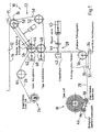
- FIG. 1 is a schematic diagram of a device 10 can be seen by means of which on a flat object 12, on its longitudinal edges 14, 15, an adhesive tape 16 glued and then subsequently crimped so that it adheres with its edge regions on the side edges of the object 12.
- an adhesive tape 16 glued and then subsequently crimped so that it adheres with its edge regions on the side edges of the object 12.
- the flat object 12 may be z. B. to act a solar cell module having disks between which the solar cells are arranged, without thereby limiting the teaching of the invention.
- a portion of the double-sided adhesive tape 16 is shown without such a portion projecting freely in practice, this would rather adhere to the longitudinal edge 16 of the object 12, wherein the longitudinal edge 14 itself is contacted directly with the adhesive tape 16. However, for purposes of illustration, the object 12 is shown spaced from the adhesive tape 16.
- a tape coil 18 to be designated as a tape coil As essential components of the device 10, a tape coil 18 to be designated as a tape coil, a cutting device 20, a device to be designated as a transport station 22 and a liner coil 24, which is also called a liner coil.
- the spool 18 On the spool 18 is preferably a multi-layered from the adhesive tape 16 and this one-sided covering liner 26 existing tape 28 is wound. This is deflected by a deflection roller 30 of approximately the horizontal in the vertical.
- the deflection roller 30 is designed as a guide roller, so it may be grooved to supply the belt 28 guided by the cutting device 20 of the transport station 22.
- the deflection roller 30 is based on a holder 32 which is pivotable about a vertically extending axis 34 so that alignment with the course of the belt 28 can then take place when the belt 28 is wound on the spool 18 in multiple rows.
- a pair of guide rollers 36 extends from the holder 32 with a clearance which corresponds to the width of the belt 28.
- the band 28 is guided over a tensioning roller 38 which pivotally extends from a lever 40.
- the tensioning roller 38 abuts against the spool 18 and is driven, wherein the direction of rotation of the tensioning roller 38 runs counter to the withdrawal direction of the belt 28 with the result that a desired belt tension is adjustable.
- the torque of the drive of the tension roller 38 is changed accordingly.
- the knife 44 which is preferably heated and / or provided with a coating such as Teflon coating, may be stationary with respect to the transport direction of the belt 28 or be mitbewegbar with this, depending on whether the severing or perforating the adhesive tape 16 is to be carried out with the belt 28 stopped or moving.
- the transport station 22 includes in the exemplary embodiment four rollers 46, 48, 50, 52 which are pivotable as a unit, in the exemplary embodiment about the axis 54 of the roller 46, which is also drive axle.
- the pivot axis can also run through another point of the transport station 22. The same applies to the drive axle.
- the rollers 46, 48 are preferably arranged one above the other along a vertical.
- the roller 50 extending above the roller 46 and laterally offset therefrom serves as a contact point or area in which the adhesive tape 16 is pressed against the longitudinal edge 14, 15 to be glued and connected thereto.
- the adhesive tape 16 without the liner 26 is thus transported by the portion of the conveyor belt 58 extending between the rollers 46, 50 and adhering thereto without contacting with other components, so that the adhesive layer is contacted with the longitudinal edge 14 of the object 12 unimpaired.
- rollers 46, 48, 50, 52 extends a conveyor belt or belt 58 on which the adhesive tape 16 adheres, so that a relative movement between the adhesive tape 16 and the conveyor belt 58 does not take place. Rather, the adhesive tape 16 is transported at the speed corresponding to that of the conveyor belt 58.
- the lower of the vertically preferably superposed rollers 46, 48 is associated with a pressure roller 60, via which the adhesive tape 16 is pressed together with the liner to the conveyor belt 58 for adhering thereto.
- a desired pressure force can be set.
- adhesion of the adhesive tape 16 on the surface of the conveyor belt 58 can be adjusted to the desired extent.
- the upper of the vertically preferably superimposed rollers 46, 48 is associated with a so-called liner withdrawal roller 62 through which the liner 26 is deflected and thus separated from the adhesive tape 16 or withdrawn to be fed via a further deflection roller 64 of the coil 24.
- the coil 24 is also driven.
- the motor one with adjustable torque can be used, via which the tension of the liner 26 can be adjusted from the liner take-off roller 62 to the winding on the shaft of the roller 24. This tension is adjusted according to the liner properties.
- the transport force for transporting the adhesive tape 16 is first transferred via the liner 26.
- the adhesive tape 16 is pressed onto the conveyor belt.
- Transport speed of the conveyor belt 58 and the liner 26 are the same.
- the liner 26 is separated from the adhesive tape 16 and thus the transport force for transporting the adhesive tape 16 is completely transferred via the transport belt 58. This measure ensures that the adhesive tape 16 is transported stress-free on the conveyor belt 58 until it is transferred to the object 12.
- the transport station 22 is pivotable, wherein the pressure roller 60 may be an integral part of the transport station 22.
- the upper pivot position reflects that in which the object 12, ie its longitudinal edge 14 should be pasted with the adhesive tape 16.
- the roller 50 performing the function of a pressure roller when pasting the edge 14 remains on the object 12.
- the unit In order to ensure a clear separation between the adhering to the edge 14 tape 16 and the adhesive on the conveyor belt 58 at the end of sticking of the edge 14 with the adhesive tape 16, the unit is in the in the Fig. 2 lower, so pivoted the retracted pivot position.
- the resulting hub ensures a clear Separation and in particular, the perforation of the adhesive tape 16 is broken perfectly in a perforated adhesive tape.
- the liner 26 is supported on the cutting table 42.
- the front cutting position of the knife 44 is set via an adjustable fixed stop. Furthermore, in the exemplary embodiment, the knife 44 is connected to a linear feed unit 45 in order to be able to cut through or sever the adhesive tape 16.
- the conveyor belt 58 or the conveyor belt is driven via the axis 56, which is moved in absolute synchronism with the movement of the object 12.
- the control of the drive shaft 56 via the control of a handling device, not shown, ie a robot, by means of which the flat object 12 is moved during the gluing with the adhesive tape 16 along the roller 50.
- the drive shaft 56 is thus a robot axis through which the velocity profile of the robot including acceleration and deceleration ramps from the conveyor 58 is mapped in real time.
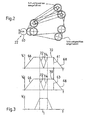
- FIG. 3 the velocity profile 61 of the robot and thus of the object 12 during the gluing of the longitudinal edge 14 with the adhesive tape 16 is shown. It can be seen the acceleration ramps 66, 68 at the beginning or end of sticking of the longitudinal edge 16. Between the ramps 66, 68 is the Object transported at a constant speed, as the plateau 70 illustrates. This speed is maintained if either the distance between the roller 50, in which the object 12 is contacted with the adhesive 16, and the separating element 44 is shorter than the length of the adhered longitudinal edge 14 or 15, or a cutting or Perforating the adhesive tape 16 is done with moving with knife 44.
- the strip 28 must first be stopped by the blade 44 in order to tune the strip length to the length of the corresponding longitudinal edge 14 or 15. For this purpose, a deceleration or acceleration of the robot and thus of the object 12 takes place. This is symbolized by the ramps 72, 74.
- An identical velocity profile 63 has the conveyor belt 58, as the middle representation in Fig. 3 clarified.
- the lower illustration of the Fig. 3 reflects the velocity profile of the knife 44 as it moves with the tape 28.
- window t1 As shown in FIG Fig. 3 the cutting through of the adhesive tape 16.
- either the knife 44 must have the same speed as the object 12 in order to cut through or perforate the adhesive tape 16, or in the window t1 the robot and thus the object 12 and thus also stop the conveyor belt 58, so that the stationary adhesive tape 16 can be cut or perforated when the knife 44 is stationary.
- a handling device 72 having a controller 70 has several axes 1, 2,. One of these axes is the drive axle for the conveyor belt 58.
- the controller 70 ensures that the resulting surface speed of the object 12 and the speed of the adhesive tape match when gluing, so that the adhesive tape 16 is applied to the predetermined contact surface of the object 12 in a tension-free manner unless controlled upsetting or stretching of the adhesive tape 16 is desired.
- the adhesive tape 16 is transferred to the object 12 in a stress-neutral manner, that is to say to the longitudinal edge 14 or 15. This is made possible by the fact that the conveyor belt 58 is moved completely synchronously when pasting the object 12 with the adhesive tape 16. Due to the pivotability of the transport station 22, the required pressurization of the adhesive tape 16 in the direction of the adhered longitudinal edge 14 and 15 is adjustable. It is not absolutely necessary that the pivot axis of the transport station 22 coincides with the drive axle 56, as has been explained in connection with FIG.
- the adhesive tape 16 is severed by means of the separator 20, 20 in the point which coincides with the coating end on the product 12, so that the longitudinal edge is accurately provided with the adhesive tape 16 from beginning to end.
- the feed of the belt 28 via the conveyor belt 58 takes place. From the roller 18 to the conveyor belt 58, the transport force is transmitted via the liner 26. Then, the transfer to the conveyor belt 58. After deduction of the liner, the conveyor belt 58 takes over completely the longitudinal forces of transport. In this case, the adhesive tape 16 rests on the conveyor belt 58 and is not stretched.
- the drive axle for the conveyor belt 58 can be changed via the controller 70 of the handling device 72 such that a compressed or stretched application of the adhesive tape 16 takes place.
- the teaching according to the invention is implemented such that the speed and acceleration profile of the object 12 is imaged in real time on the drive axle of the transport device, wherein the speed or acceleration of the surface speed of the object 12 deviates from the tape feed speed by a predetermined factor, to ensure the desired compressed or stretched order controlled.
- the adhesive tape 16 projects laterally beyond the longitudinal edge 14 or 15. In a subsequent processing station, the laterally projecting edges are crimped to be pressed against the longitudinal side edges of the object 12.
- teaching according to the invention is described with reference to a double adhesive tape with a liner, then the teaching according to the invention is not limited by this. It is also possible to use a double-sided tape with two liners, one of the liners being peeled off before the separator. Also, if desired, an adhesive tape could be used which does not necessarily have an adhesive layer on both sides. However, make sure that the tape from the conveyor belt is detected such that a relative movement between this can not be done after placing the adhesive tape on the conveyor belt.
- the method according to the invention is preferably used for gluing the peripheral edges of a solar cell module. But this also does not limit the teaching of the invention.
Description
Die Erfindung bezieht sich auf ein Verfahren zum Bekleben eines Objekts mit einem vorzugsweise einen Liner aufweisenden Klebeband, insbesondere zum Be- bzw. Umkleben eines Rands eines flächigen Objekts, wobei das Objekt mit dem Klebeband kontaktiert und während des Transports des Objekts mit dem gleichfalls transportierten Klebeband auf das Objekt aufgebracht wird, und wobei die Geschwindigkeit von dem Objekt und die des Klebebands während des Beklebens synchronisiert werden.The invention relates to a method for pasting an object with a preferably having a liner adhesive tape, in particular for loading or pasting an edge of a flat object, wherein the object contacted with the adhesive tape and during transport of the object with the likewise transported adhesive tape is applied to the object, and wherein the speed of the object and the adhesive tape are synchronized during pasting.
Ferner nimmt die Erfindung Bezug auf eine Vorrichtung zum Bekleben eines Objekts, insbesondere zum Be- bzw. Umkleben eines Rands eines flächigen Objekts, mit einem vorzugsweise einen Liner aufweisenden Klebeband, umfassend eine Bevorratung wie Spule für das Klebeband, eine Schneideinrichtung, eine das Klebeband dem Objekt zuführende Einrichtung sowie einen ersten Antrieb wie die Einrichtung und einen zweiten Antrieb wie das Objekt, wobei die Antriebe zum Transportieren des Klebebands und des Objekts synchronisierbar sind.Furthermore, the invention relates to a device for adhering an object, in particular for applying or re-adhering an edge of a flat object, preferably with a liner having adhesive tape, comprising a storage such as coil for the tape, a cutter, the adhesive tape the Object supplying device and a first drive as the device and a second drive such as the object, wherein the drives for transporting the adhesive tape and the object are synchronized.
Bei flächigen Objekten wie Solarzellenmodulen ist es erforderlich, dass die Längsränder der die Solarzellen außenseitig umgebenden Scheiben von einem Klebeband abgedeckt werden, das sodann umgebördelt wird, also sich entlang der Seitenränder der Scheiben erstreckt und an diesen anklebt.In the case of flat objects such as solar cell modules, it is necessary for the longitudinal edges of the panes surrounding the solar cells to be covered by an adhesive tape, which is then flanged over, that extends along the side edges of the panes and adheres to them.
Bei den bekannten Verfahren wird das Objekt (z. B. Solarmodul) auf das Klebeband aufgesetzt. Durch die Vorschubbewegung des Objektes mittels einer Handhabungseinrichtung, wie z. B. eines Roboters wird das Klebeband durch die Kontaktreibung/-kraft zwischen Klebeband und der Kante des Objektes von der Bereitstellungsrolle abgezogen und haftet an der Kante des Objektes. Das Band wird gegebenenfalls anschließend noch um die Kante umgebördelt. Das Abziehen des Klebebands erfolgt durch die Bewegung des Moduls, so dass infolgedessen während des Abziehens ein Dehnen des Bands erfolgt. Folglich gelangt ein vorgespanntes Klebeband auf die Außenränder der Scheiben, so dass dann, wenn dieses nicht haften bleiben sollte, sich dieses verkürzt und somit der Rand nicht vollständig umklebt wird. Ein weiterer Nachteil der bekannten Verfahren besteht darin, dass vor dem Kontaktieren des Klebebands mit dem Objekt die mit dem Rand in Berührung gelangende Seite mit Komponenten des Klebebands der Abspulvorrichtung in Berührung gelangt ist, so dass hierdurch eine Beeinträchtigung der Klebewirkung auftreten kann.In the known methods, the object (eg solar module) is placed on the adhesive tape. By the feed movement of the object by means of a handling device, such. As a robot, the adhesive tape is pulled off by the contact friction / force between the adhesive tape and the edge of the object from the supply roll and adheres to the edge of the object. If necessary, the band is subsequently crimped around the edge. The tape is peeled off by the movement of the module, as a result of which the tape is stretched during peeling. Consequently, a pre-tensioned adhesive tape reaches the outer edges of the panes, so that if this should not stick, this is shortened and thus the edge is not completely re-adhered. A further disadvantage of the known methods is that, prior to contacting the adhesive tape with the object, the side in contact with the edge has come into contact with components of the adhesive tape of the unwinding device, so that an impairment of the adhesive effect can thereby occur.
Der
Die
Gegenstand der
Der vorliegenden Erfindung liegt die Aufgabe zugrunde, ein Verfahren und eine Vorrichtung der eingangs genannten Art so weiterzubilden, dass ein Bekleben eines Objekts, insbesondere ein Be- bzw. Umkleben eines flächigen Objekts erfolgt, ohne dass eine Beeinflussung des Klebebands erfolgen kann, durch die die Klebewirkung beeinträchtigt werden könnte. Auch soll ein Klebeprozess ermöglicht werden, der zu einer reproduzierbaren Qualität führt.The present invention has the object, a method and an apparatus of the type mentioned in such a way that a gluing of an object, in particular a loading or re-adhering a flat object takes place without any influence of the adhesive tape can be done by the Adhesive effect could be impaired. Also, an adhesive process is to be made possible, which leads to a reproducible quality.
Verfahrensmäßig wird die Aufgabe im Wesentlichen dadurch gelöst, dass das Objekt mittels einer Handhabungseinrichtung transportiert wird und dass sowohl Geschwindigkeitsals auch Beschleunigungsverlauf des Objekts synchron über eine Achse des Handhabungsgerätes auf den Transport des Klebebands übertragen wird, und somit das Objekt und das Klebeband quasi mittels einer gemeinsamen elektronischen Welle bewegt werden.In terms of method, the object is essentially achieved in that the object is transported by means of a handling device and that both speed and acceleration characteristics of the object are transmitted synchronously to the transport of the adhesive tape via an axis of the handling device, and thus the object and the adhesive tape are quasi by means of a common be moved electronic wave.
Erfindungsgemäß wird das Objekt mittels einer Handhabungseinrichtung transportiert, deren Steuerung Geschwindigkeits- und Beschleunigungsverlauf des transportierten Objekts in Echtzeit auf den Transport des Klebebands abbildet.According to the invention, the object is transported by means of a handling device whose control system maps the speed and acceleration profile of the transported object in real time to the transport of the adhesive tape.
Das Klebeband wird nicht durch Kontaktreibung bzw. -kraft zu dem Objekt mitbewegt. Es erfolgt keine Dehnung des Klebebands, so dass dieses spannungsfrei auf das Objekt wie einen Rand aufgeklebt wird. Dabei ist insbesondere vorgesehen, dass das Klebeband von der Bereitstellungseinheit, also insbesondere der Rolle, auf der das Klebeband aufgewickelt ist, ohne Dehnung abgezogen und transportiert wird.The adhesive tape is not moved by contact friction or force to the object. There is no stretching of the adhesive tape, so that this tension-free is glued to the object like an edge. In this case, provision is made in particular for the adhesive tape to be removed from the supply unit, that is to say in particular the roll on which the adhesive tape is wound, without stretching and transported.
Das Klebeband wird aktiv transportiert, wobei Geschwindigkeits- und Beschleunigungsverlauf des transportierten Objekts auf den Transport des Klebebands übertragen werden. Objekt und Klebeband werden quasi mittels einer gemeinsamen elektronischen Welle bewegt, so dass ein präzises Aufkleben des Klebebands auf das Objekt sichergestellt ist. Die Gefahr einer Faltenbildung oder eines Reißens ist somit ausgeschlossen.The adhesive tape is actively transported, whereby the speed and acceleration of the transported object are transferred to the transport of the adhesive tape. The object and the adhesive tape are moved, so to speak, by means of a common electronic wave, so that a precise adhesion of the adhesive tape to the object is ensured. The risk of wrinkling or tearing is thus excluded.
Dies schließt jedoch nicht aus, dass die Synchronisierung des Geschwindigkeits- und Beschleunigungsverlaufs derart erfolgt, dass gezielt und damit kontrolliert eine gewünschte Spannung in das Klebeband eingebracht werden kann, sei es stauchend, sei es dehnend. Bevorzugterweise erfolgt jedoch ein spannungsfreies Aufkleben.However, this does not rule out that the synchronization of the speed and acceleration curve takes place in such a way that targeted and thus controlled a desired tension can be introduced into the adhesive tape, be it upsetting, be it expansive. Preferably, however, a tension-free bonding takes place.
Ein gestauchter bzw. gestreckter Auftrag von Klebebändern kann bei bestimmten Applikationen vorteilhaft sein. Dieser kann ganzseitig oder auch partiell erfolgen. Bei starken Umorientierungen in der Kleberauftragsbahn (z. B. Ecken umlaufend bekleben) kann ein gestauchter und/oder gestreckter Auftrag vorteilhaft sein, um ein besseres Anlegen des Produktes zu ermöglichen.A compressed or stretched application of adhesive tapes may be advantageous in certain applications. This can be done full-page or partial. In the case of strong reorientations in the adhesive application web (eg gluing corners all round), an upset and / or stretched application can be advantageous in order to enable a better application of the product.
Des Weiteren können durch den gestauchten bzw. gestreckten Auftrag (bei geeigneten Klebebändern) Produkteigenschaften wie Tape-Höhe und -Breite ebenso gezielt beeinflusst werden, wie auch die Dichte eines des aufgetragenen Tapes.Furthermore, the compressed or stretched application (with suitable adhesive tapes) product properties such as tape height and width can also be selectively influenced, as well as the density of the applied tape.
So können bei geeigneten Klebebändern abweichende Produkteigenschaften erzeugt werden, zum Beispiel Größe des Auftrags, Härte des Klebebands usw.. Des Weiteren kann bei starken Umorientierungen, z. B. Ecken, welche umklebt werden müssen, ein Stauchen oder Strecken des Produktes von Vorteil sein.Thus, deviating product properties can be produced with suitable adhesive tapes, for example, the size of the job, the hardness of the adhesive tape, etc. Furthermore, in the case of strong reorientations, eg. As corners, which must be glued, upsetting or stretching the product be beneficial.
Die Transporteinrichtung für das Klebeband wird erfingdungsgemäß über eine zusätzliche Achse der Handhabungseinrichtung, z. B. eines Roboters angetrieben, welche sich absolut synchron zur Bewegung des Objekts bewegt.The transport device for the adhesive tape is erfingdungsgemäß on an additional axis of the handling device, eg. B. a robot driven, which moves absolutely synchronously with the movement of the object.
Die Ansteuerung der Achse erfolgt über die Steuerung der Handhabungseinrichtung, so dass dessen infolge das Geschwindigkeitsprofil der Handhabungseinrichtung wie des Roboters und damit die Bewegung des Objekts einschließlich Beschleunigungs- und Verzögerungsrampen von der das Klebeband transportierenden Einrichtung in Echtzeit mit abgebildet wird.The control of the axis takes place via the control of the handling device, so that its due to the speed profile of the handling device such as the robot and thus the movement of the object including acceleration and deceleration ramps from the device transporting the tape is mapped in real time.
Aufgrund der erfindungsgemäßen Lehre kann die Länge des Kontaktbereichs, in dem das Klebeband auf der Transporteinrichtung fixiert ist und mittels der das Klebeband sodann auf das Objekt übergeben wird, unabhängig von der Länge des aufzutragenden Klebebands sein. Mit anderen Worten kann die Kontaktlänge gleich oder abweichend von der Länge des Klebebandabschnitts sein, der auf das Objekt geklebt wird.Due to the teaching of the invention, the length of the contact region in which the adhesive tape is fixed on the transport device and by means of the adhesive tape then transferred to the object, regardless of the length of the adhesive tape to be applied. In other words, the contact length may be equal to or different from the length of the adhesive tape portion adhered to the object.
Insbesondere wird als Transporteinrichtung für das Klebeband ein Transportband wie ein Transportriemen verwendet, gleichwenn auch andere geeignete Mittel wie Transportrolle oder -rad mit geeignet großem Durchmesser in Frage kommen.In particular, a transport belt such as a transport belt is used as the transport device for the adhesive tape, although other suitable means such as a transport roller or wheel with a suitably large diameter come into consideration.
Insbesondere ist vorgesehen, dass das Transportband über eine Rolle mit einer Antriebsachse geführt wird, die über die Steuerung der Handhabungseinrichtung betätigt wird.In particular, it is provided that the conveyor belt is guided over a roller with a drive axle, which is actuated via the control of the handling device.
Das Transportband wird zumindest über zwei, vorzugsweise über drei, insbesondere über vier Rollen geführt, die insgesamt als Einheit schwenkbar sind. Im Bereich einer der Rollen wird sodann das Klebeband mit dem Objekt in Kontakt gebracht. Hierzu wird die Einheit in Richtung des Objekts verschwenkt, so dass das Klebeband im erforderlichen Umfang an den Rand anhaften und auf diesen gedrückt werden kann.The conveyor belt is guided over at least two, preferably three, in particular four rollers, which are pivotable as a whole as a whole. In the area of one of the rollers, the adhesive tape is then brought into contact with the object. For this purpose, the unit is pivoted in the direction of the object, so that the adhesive tape can adhere to the required extent to the edge and can be pressed onto this.
In Weiterbildung der Erfindung ist vorgesehen, dass die das Transportband bzw. den Transportriemen führenden Rollen zwei vorzugsweise vertikal übereinander angeordnete Rollen umfassen, wobei einer, vorzugsweise unterer der zwei Rollen eine Andrückrolle zum Anhaften des Klebebands an das Transportband zugeordnet wird.In a further development of the invention, it is provided that the rollers guiding the conveyor belt or transport belts comprise two rollers, preferably arranged vertically one above the other, wherein one, preferably lower, of the two rollers is assigned a pressure roller for adhering the adhesive tape to the conveyor belt.
Der anderen, vorzugsweise der oberen der zwei Rollen sollte eine Linerumlenkrolle oder -abzug zugeordnet sein, über die der Liner von dem Klebeband getrennt bzw. abgezogen wird und einer den Liner aufwickelnden angetriebenen Welle oder Rolle zugeführt wird. Dabei kann die den Liner aufwickelnde Welle oder Rolle über einen Motor mit einstellbarem Drehmoment angetrieben werden, um die erforderliche Linerspannung sicherzustellen. Die den Liner aufwickelnde Welle wirkt bis zur Linerumlenk- oder -abzugsrolle bzw. bis zur Transporteinrichtung. Durch die Transporteinrichtung wird ein den Liner mit dem Klebeband aufweisendes Band von einer Spule abgezogen. Dabei kann das Band ein- oder mehrreihig aufgewickelt sein.The other, preferably the upper, of the two rollers should be associated with a liner deflection roller or pullout over which the liner is separated from the adhesive tape and fed to a driven shaft or roller winding the liner. The liner or reel winding up the liner may be driven by an adjustable torque motor to ensure the required liner tension. The liner winding shaft acts up to the Linerumlenk- or -abzugsrolle or to the transport device. By the transport device, the liner with the tape exhibiting tape is withdrawn from a spool. The tape can be wound in one or more rows.
Der Spule sollte eine Spannrolle zugeordnet sein, die an der Spule selbst anliegt, wobei die Spannrolle entgegen der Abzugsrichtung des Bands angetrieben wird. Insbesondere kann die Spannung des Bands über das Drehmoment des Antriebs der Spannrolle eingestellt werden.The spool should be associated with a tensioning roller which bears against the spool itself, the tensioning spool being driven counter to the withdrawal direction of the belt. In particular, the tension of the belt can be adjusted via the torque of the drive of the tensioning roller.
Für den Fall, dass das Band mehrreihig auf die Spule aufgewickelt ist, wird das Band über Führungsrollen geführt. Hierbei kann es sich um genutete Rollen oder um zueinander beabstandete Führungsrollen handeln, um eine ordnungsgemäße Ausrichtung auf das Transportband bzw. den Transportriemen und somit auf das Objekt sicherzustellen.In the event that the tape is wound on the spool in several rows, the tape is guided over guide rollers. These may be grooved rollers or spaced-apart guide rollers to ensure proper alignment with the conveyor belt or belt and thus with the object.
Unabhängig hiervon wird das von der Spule abgezogene Band über eine Führungsrolle zur Vertikalen hin umgelenkt. Dabei kann die Führungsrolle von einer Halterung ausgehen, die um eine vertikal verlaufende Achse drehbar ist, so dass eine Ausrichtung auf das von der Spule abgezogene Band erfolgt.Independently of this, the strip drawn off from the bobbin is deflected towards the vertical via a guide roller. In this case, the guide roller can start from a holder, which is rotatable about a vertically extending axis, so that an alignment takes place on the withdrawn from the coil band.
Des Weiteren ist vorgesehen, dass zwischen der Umlenkrolle und dem Transportband eine Schneideinrichtung angeordnet wird, mittels der das Klebeband in Abhängigkeit von seiner auf das Objekt aufzuklebenden Länge ohne Durchtrennung des Liners durchschnitten bzw. perforiert wird. Während des Durchschneidens bzw. Perforierens kann der Vorschub des Klebebandes und somit auch die Bewegung des Handhabungsgerätes angehalten werden. Es besteht jedoch auch die Möglichkeit, dass ein Trennelement synchron mit der Transportgeschwindigkeit des Klebebandes mitbewegt wird, so dass ohne Anhalten des Objekts und somit des Transportbands ein Durchtrennen bzw. Perforieren möglich ist.Furthermore, it is provided that a cutting device is arranged between the deflection roller and the conveyor belt, by means of which the adhesive tape is cut or perforated as a function of its length to be adhered to the object without severing the liner. During the cutting or perforation, the advance of the adhesive tape and thus also the movement of the handling device can be stopped. However, there is also the possibility that a separating element is moved synchronously with the transport speed of the adhesive tape, so that a severing or perforation is possible without stopping the object and thus the conveyor belt.
Unabhängig hiervon sollte ein Trennelement wie Messer verwendet werden, das z. B. mit Teflon beschichtet und/oder beheizbar ist, um Kontaminationen durch den Klebstoff des Klebebands zu verhindern, wodurch andernfalls ein präzises Durchtrennen oder Perforieren des Klebebands nicht möglich wäre bzw. beeinträchtigt werden würde.Regardless of this, a separator such as knives should be used, the z. B. coated with Teflon and / or is heated to prevent contamination by the adhesive of the adhesive tape, which would otherwise not possible precise cutting or perforation of the adhesive tape would be or would be affected.
Eine Vorrichtung der eingangs genannten Art zeichnet sich dadurch aus, dass das Objekt über eine Handhabungseinrichtung transportierbar ist, deren Steuerung, Geschwindigkeits- und Beschleunigungsverlauf des Objekts auf eine Antriebsachse einer die Einrichtung umfassenden Klebeband-Transporteinrichtung während des Beklebens des Objekts mit dem Klebeband in Echtzeit abbildet, und somit das Objekt und das Klebeband quasi mittels einer gemeinsamen elektronischen Welle bewegbar sind.A device of the type mentioned above is characterized in that the object is transportable via a handling device whose control, speed and acceleration curve of the object on a drive axle of the device comprising the adhesive tape transport device during pasting of the object with the adhesive tape in real time , And thus the object and the adhesive tape are virtually movable by means of a common electronic wave.
Dabei ist insbesondere vorgesehen, dass die Länge des Kontaktbereichs für das Klebeband auf der Transporteinrichtung unabhängig von der Länge des auf das Objekt aufzutragenden Klebebandabschnitts ist.It is provided in particular that the length of the contact region for the adhesive tape on the transport device is independent of the length of the adhesive tape section to be applied to the object.
Ferner ist das Klebeband bevorzugterweise mit einem Liner verbunden, so dass das Klebeband auf die Transporteinrichtung spannungsfrei übertragen wird, da die Transportkraft zum Transport des Klebebandes in den Liner eingeleitet wird.Furthermore, the adhesive tape is preferably connected to a liner, so that the adhesive tape is transferred to the transport device stress-free, since the transport force for transporting the adhesive tape is introduced into the liner.
Über den Liner wird die Transportkraft bis zur Transporteinrichtung übertragen. Während des Kontakts des Klebebands mit der Transporteinrichtung sind Transportgeschwindigkeit des Liners und Transportgeschwindigkeit der Transporteinrichtung gleich. Nach einer vorgegebenen Transportstrecke auf der Transporteinrichtung wird sodann der Liner von dem Klebeband getrennt und die Transportkraft über die Transporteinrichtung übertragen. Somit ist sichergestellt, dass auf den Kleber keine unkontrollierten Kräfte einwirken.About the liner, the transport force is transmitted to the transport device. During the contact of the adhesive tape with the transport device, the transport speed of the liner and the transport speed of the transport device are the same. After a predetermined transport distance on the transport device, the liner is then separated from the adhesive tape and the transport force is transmitted via the transport device. This ensures that no uncontrolled forces act on the adhesive.
Die Transporteinrichtung, mittels der das Klebeband auf das Objekt übergeben wird, sollte zumindest zwei ein das Klebeband aufnehmendes Transportband führende Rollen umfassen, von denen eine eine Antriebsachse aufweist, die über die Steuerung der Handhabungseinrichtung betätigbar ist.The transport device, by means of which the adhesive tape is transferred to the object, should comprise at least two rollers carrying the adhesive tape, one of which has a drive axis which can be actuated by the control of the handling device.
Alternativ kann als die Einrichtung eine Transportrolle bzw. ein Transportrad zur Aufnahme und Transport des Klebebands eingesetzt werden, die über die Steuerung der Handhabungseinrichtung betätigbar ist.Alternatively it can be used as the device, a transport roller or a transport wheel for receiving and transporting the adhesive tape, which can be actuated via the control of the handling device.
Die zumindest zwei Rollen sollten als Einheit schwenkbar zu der Handhabungseinrichtung ausgebildet sein, um somit mit der erforderlichen Druckbeaufschlagung das Transportband und folglich das Klebeband gegen das Objekt drücken zu können.The at least two rollers should be designed to be pivotable as a unit to the handling device, so as to be able to press the conveyor belt and consequently the adhesive tape against the object with the required pressurization.
Insbesondere ist jedoch vorgesehen, dass die Einheit zumindest drei, vorzugsweise vier das Transportband führende Rollen umfasst. Dabei sollten vorzugsweise zwei der zumindest drei Rollen vertikal übereinander angeordnet sein.In particular, however, it is provided that the unit comprises at least three, preferably four rollers leading the conveyor belt. In this case, preferably two of the at least three rollers should be arranged vertically one above the other.
In einer Ausgestaltung der Erfindung wird vorgeschlagen, dass oberer der zwei vertikal vorzugsweise übereinander angeordneten Rollen eine Linerumlenkrolle zugeordnet ist, über die der von dem Klebeband getrennte bzw. abgezogene Liner einer diesen aufnehmenden Welle zuführbar ist. Dabei sollte die den Liner aufwickelnde Welle über einen Motor mit einstellbarem Drehmoment antreibbar sein, um so die gewünschte Linerspannung sicherzustellen.In one embodiment of the invention it is proposed that upper of the two vertically preferably superimposed rollers is associated with a Linerumlenkrolle over which the separated or deducted from the adhesive liner of a receiving this shaft can be fed. In this case, the shaft winding up the liner should be drivable via a motor with adjustable torque, so as to ensure the desired liner tension.
Der unteren der zwei vertikal vorzugsweise übereinander angeordneten Rollen sollte eine das Klebeband auf das Transportband drückende Andrückrolle zugeordnet sein.The lower of the two vertically preferably superimposed rollers should be assigned to a pressure belt pressing the adhesive tape on the conveyor belt.
Versetzt und oberhalb der oberen Rolle verläuft sodann eine Rolle der Einheit, die Aufgabepunkt bzw. -bereich des Klebebands auf den Rand des Objekts ist.Offset and above the upper roll then passes a roll of the unit, which is the point of application or area of the adhesive tape to the edge of the object.
Selbstverständlich ist eine vertikale Ausrichtung der Rollen nicht zwingend erforderlich. Es kann die Vorrichtung auch verdreht zum Einsatz kommen. Auch Variationen in den Umlenkungswinkeln des Bands (Tapes) von der Spule zur Andrückrolle sind möglich.Of course, a vertical alignment of the rollers is not mandatory. It can also be twisted the device used. Also, variations in the deflection angles of the tape (tapes) from the spool to the pressure roller are possible.
In Weiterbildung ist vorgesehen, dass der das ein- oder mehrreihige Band aufweisenden Spule eine an dieser anliegende Spannrolle zugeordnet ist, die entgegen der Bandabzugsrichtung mit vorzugsweise einstellbarem Drehmoment angetrieben ist. Somit kann mit einfachen Maßnahmen die Vorspannung eingestellt werden.In a further development, it is provided that the coil having the single or multi-row band is assigned a tensioning roller which bears on it and which is driven counter to the band withdrawal direction with preferably adjustable torque. Thus, the bias can be adjusted with simple measures.
Zwischen der Spule und der vorzugsweise vier Rollen aufweisenden verschwenkbaren Einheit ist des Weiteren eine das Band von in etwa der Horizontalen in die Vertikale umlenkende Umlenkrolle angeordnet. Ferner kann vor und/oder hinter der Umlenkrolle zumindest ein das Band seitlich führende Führungseinrichtung angeordnet sein, insbesondere dann, wenn das Band mehrreihig auf der Rolle aufgewickelt ist.Between the coil and the preferably four rollers having pivotable unit is further a the band from approximately horizontal to vertical deflecting pulley arranged. Furthermore, before and / or behind the deflection roller, at least one guide device which laterally guides the belt can be arranged, in particular when the belt is wound in a multi-row manner on the roller.
Die Führungseinrichtung kann zwei sich um vertikal verlaufende Achsen drehende Führungsrollen umfassen. Auch oder ergänzend ist eine genutete Führungsrolle in Betracht zu ziehen, wobei die Breite der Nut der des Bandes entspricht.The guide means may comprise two guide rollers rotating about vertical axes. Also or in addition, a grooved guide roller is to be considered, wherein the width of the groove corresponds to that of the band.
Zwischen der Umlenkrolle und der das Transportband aufweisenden Einheit ist eine Schneideinrichtung angeordnet, die vorzugsweise ein beheizbares und/oder beschichtetes Trennelement wie Messer umfasst. Als Beschichtung kommt z. B. Teflon in Frage.Between the deflection roller and the conveyor belt unit having a cutting device is arranged, which preferably comprises a heatable and / or coated separating element such as knives. As a coating comes z. As Teflon in question.
Das Trennelement kann zum Durchtrennen bzw. Perforieren des Klebebands, ohne dass der Liner mit durchtrennt bzw. perforiert wird, mit dem Band mitbewegt werden, folglich kann ein sogenanntes fliegendes Messer zum Einsatz gelangen. Hierdurch ergibt sich der Vorteil, dass zum Durchtrennen bzw. Perforieren des Klebebands die Handhabungseinrichtung und somit das Transportband nicht angehalten werden muss.The separating element can be moved along with the band for severing or perforating the adhesive tape, without the perforator being severed or perforated, and consequently a so-called flying knife can be used. This results in the advantage that for severing or perforating the adhesive tape, the handling device and thus the conveyor belt does not have to be stopped.
Um ein Ausweichen des Bands auszuschließen, sieht eine Weiterbildung vor, dass die Schneideinrichtung eine Schneidabstützung wie -tisch aufweist, auf der bzw. den bei Durchtrennen bzw. Perforieren des Klebebands der Liner aufliegt bzw. abgestützt ist.To preclude deflection of the band, a further development provides that the cutting device has a cutting support, such as a table, on which the liner rests or is supported when the adhesive tape is severed or perforated.
Weitere Einzelheiten, Vorteile und Merkmale der Erfindung ergeben sich nicht nur aus den Ansprüchen, den diesen zu entnehmenden Merkmalen -für sich und/oder in Kombination-, sondern auch aus der nachfolgenden Beschreibung eines der Zeichnung zu entnehmenden bevorzugten Ausführungsbeispiels.Further details, advantages and features of the invention will become apparent not only from the claims, the features to be taken from them-alone and / or in combination-but also from the following description of a preferred embodiment to be taken from the drawing.
Es zeigen:
- Fig. 1
- eine Vorrichtung zum Bekleben eines Rands eines flächigen Objekts,
- Fig. 2
- ein Detail der
Fig. 1 , - Fig. 3
- Geschwindigkeitsprofile von Elementen der Vorrichtung gemäß
Fig. 1 und - Fig. 4
- ein Blockdiagramm.
- Fig. 1
- a device for bonding an edge of a flat object,
- Fig. 2
- a detail of
Fig. 1 . - Fig. 3
- Velocity profiles of elements of the device according to
Fig. 1 and - Fig. 4
- a block diagram.
Die erfindungsgemäße Lehre wird anhand des Umklebens eines Randes eines flächigen Objektes wie Solarzellenmodul erläutert, ohne dass hierdurch eine Einschränkung erfolgen soll. Vielmehr ist die erfindungsgemäße Lehre für jedwedes Auftragen eines Klebebandes auf ein Objekt geeignet, das zudem einer ebenen Oberfläche nicht bedarf. Hierzu besteht die Möglichkeit, die Geschwindigkeit bzw. Beschleunigung des Objekts auf die wirksame Länge des zu beklebenden Bereichs abzustimmen. Dies erfolgt mittels einer Handhabungseinrichtung wie Roboter. Da das Klebeband aufgrund der erfindungsgemäßen Lehre einen identischen Geschwindigkeits- und Beschleunigungsverlauf wie das Handhabungsgerät aufweist, kann das Klebeband spannungsfrei aufgetragen werden. Dabei ist selbstverständlich sicherzustellen, dass das Andruckelement, mittels dessen das Klebeband auf das Objekt gedrückt wird, der entsprechenden Oberflächenkontur folgen kann.The teaching according to the invention is explained on the basis of the gluing of an edge of a planar object such as a solar cell module, without this being intended to limit it. Rather, the teaching of the invention is suitable for any application of an adhesive tape to an object, which also does not require a flat surface. For this purpose, it is possible to tune the speed or acceleration of the object to the effective length of the area to be adhered. This is done by means of a handling device such as robots. Since the adhesive tape has an identical speed and acceleration profile as the handling device due to the teaching according to the invention, the adhesive tape can be applied stress-free. Of course, it must be ensured that the pressure element, by means of which the adhesive tape is pressed onto the object, can follow the corresponding surface contour.
Der
In der
Als wesentliche Bauteile der Vorrichtung 10 sind eine auch als Tape-Coil zu bezeichnende Bandspule 18, eine Schneideinrichtung 20, eine als Transportstation 22 zu bezeichnende Einrichtung sowie eine Linerspule 24 zu bezeichnen, die auch Liner-Coil genannt wird.As essential components of the
Auf der Spule 18 ist vorzugsweise mehrreihig ein aus dem Klebeband 16 und dieses einseitig abdeckendem Liner 26 bestehendes Band 28 aufgewickelt. Dieses wird über eine Umlenkrolle 30 von in etwa der Horizontalen in die Vertikale umgelenkt. Die Umlenkrolle 30 ist als Führungsrolle ausgebildet, kann also genutet sein, um das Band 28 geführt durch die Schneideinrichtung 20 der Transportstation 22 zuzuführen.On the
Die Umlenkrolle 30 geht von einer Halterung 32 aus, die um eine vertikal verlaufende Achse 34 schwenkbar ist, so dass eine Ausrichtung auf den Verlauf des Bands 28 dann erfolgen kann, wenn auf der Spule 18 mehrreihig das Band 28 aufgewickelt ist.The
Zur Führung des Bands 28 geht von der Halterung 32 ein Führungsrollenpaar 36 mit einem lichten Abstand aus, der der Breite des Bands 28 entspricht.For guiding the
Um das Band 28 im gewünschten Umfang vorzuspannen, wird das Band 28 über eine Spannrolle 38 geführt, die schwenkbar von einem Hebel 40 ausgeht. Die Spannrolle 38 liegt an der Spule 18 an und wird angetrieben, wobei die Drehrichtung der Spannrolle 38 entgegen der Abzugsrichtung des Bands 28 verläuft mit der Folge, dass eine gewünschte Bandspannung einstellbar ist. Hierzu ist auch das Drehmoment des Antriebs der Spannrolle 38 entsprechend veränderbar.To bias the
Das Band 28 durchläuft nach dessen vertikaler Ausrichtung die Trenneinrichtung 20, die eine Schneidabstützung bzw. einen Schneidtisch 42 auf der Seite des Liners 26 und ein Trennelement wie Messer 44 auf der Seite des Klebebands 16 aufweist. Das Messer 44, das vorzugsweise beheizt und/oder mit einer Beschichtung wie Teflonbeschichtung versehen ist, kann im Bezug auf die Transportrichtung des Bands 28 stationär ausgebildet oder mit dieser mitbewegbar sein, je nach dem, ob das Durchtrennen bzw. Perforieren des Klebebands 16 bei angehaltenem oder sich bewegendem Band 28 durchgeführt werden soll.The
Die Transportstation 22 umfasst im Ausführungsbeispiel vier Rollen 46, 48, 50, 52, die als Einheit schwenkbar sind, und zwar im Ausführungsbeispiel um die Achse 54 der Rolle 46, die gleichzeitig Antriebsachse ist. Hierdurch erfolgt jedoch eine Beschränkung der erfindungsgemäßen Lehre nicht. Die Schwenkachse kann auch durch einen anderen Punkt der Transportstation 22 verlaufen. Gleiches gilt für die Antriebsachse.The
Die Rollen 46, 48 sind übereinander vorzugsweise entlang einer Vertikalen angeordnet. Die oberhalb der Rolle 46 und seitlich versetzt zu dieser verlaufende Rolle 50 dient als Kontaktpunkt bzw. -bereich, in dem das Klebeband 16 an den zu beklebenden Längsrand 14, 15 angedrückt und mit diesem verbunden wird. Das Klebeband 16 ohne den Liner 26 wird folglich von dem zwischen den Rollen 46, 50 verlaufenden Abschnitt des Transportbands 58 und an diesem anhaftend ohne Kontaktierung mit anderen Bauelementen transportiert, so dass die Klebeschicht unbeeinträchtigt mit dem Längsrand 14 des Objekts 12 kontaktiert wird.The
Um die Rollen 46, 48, 50, 52 verläuft ein Transportband oder -riemen 58, auf dem das Klebeband 16 haftet, so dass eine Relativbewegung zwischen dem Klebeband 16 und dem Transportband 58 nicht erfolgt. Vielmehr wird das Klebeband 16 mit der Geschwindigkeit transportiert, die der des Transportbands 58 entspricht.To the
Der unteren der vertikal vorzugsweise übereinander angeordneten Rollen 46, 48 ist eine Andrückrolle 60 zugeordnet, über die das Klebeband 16 zusammen mit dem Liner an das Transportband 58 zum Haften an diesem angedrückt wird. Dabei kann eine gewünschte Andruckkraft eingestellt werden. Auch kann durch Festlegen eines Spalts zwischen den Oberflächen der Andrückrolle 60 und der zugeordneten Rolle 48 der Transportstation 22 oder durch Kombination von Andruckkraft und Spalt das Anhaften des Klebebands 16 auf der Oberfläche des Transportbands 58 in gewünschtem Umfang eingestellt werden.The lower of the vertically preferably superposed
Der oberen der vertikal vorzugsweise übereinander angeordneten Rollen 46, 48 ist eine sogenannte Linerabzugsrolle 62 zugeordnet, über die der Liner 26 umgelenkt und somit von dem Klebeband 16 getrennt bzw. abgezogen wird, um über eine weitere Umlenkrolle 64 der Spule 24 zugeführt zu werden. Die Spule 24 ist gleichfalls angetrieben. Als Motor kann ein solcher mit einstellbarem Drehmoment verwendet werden, über das die Spannung des Liners 26 von der Linerabzugsrolle 62 bis zur Aufwicklung auf die Welle der Rolle 24 eingestellt werden kann. Diese Spannung wird entsprechend der Linereigenschaften eingestellt.The upper of the vertically preferably superimposed
Die Transportkraft zum Transportieren des Klebebands 16 wird zunächst über den Liner 26 übertragen. Über die Andrückrolle 60 wird das Klebeband 16 auf das Transportband gedrückt. Transportgeschwindigkeit des Transportbands 58 und des Liners 26 sind gleich. Im Bereich der Linerabzugsrolle 62 wird der Liner 26 von dem Klebeband 16 getrennt und somit die Transportkraft zum Transport des Klebebands 16 vollständig über das Transportband 58 übertragen. Durch diese Maßnahme ist sichergestellt, dass das Klebeband 16 spannungsfrei auf dem Transportband 58 bis zu Übergabe auf das Objekt 12 transportiert wird.The transport force for transporting the
Wie sich aus der
In der
Während des Schneidvorgangs verbleibt die beim Bekleben des Rands 14 die Funktion einer Andrückrolle ausübende Rolle 50 an dem Objekt 12.During the cutting process, the
Um am Ende des Beklebens des Rands 14 mit dem Klebeband 16 eine klare Trennung zwischen dem an dem Rand 14 klebenden Band 16 und dem auf dem Transportband 58 haftenden sicherzustellen, wird die Einheit in die in der
Damit beim Ausweichen während des Durchtrennens bzw. Perforierens des Klebebands das Band nicht ausweichen kann, wird der Liner 26 an dem Schneidtisch 42 abgestützt.So that the band can not escape during deflection during the cutting or perforation of the adhesive tape, the
Um sicherzustellen, dass der Liner 26 nicht durchtrennt wird, wird die vordere Schneidposition des Messers 44 über einen einstellbaren Festanschlag festgelegt. Ferner ist das Messer 44 im Ausführungsbeispiel mit einer linearen Vorschubeinheit 45 verbunden, um das Klebeband 16 durchschneiden bzw. durchtrennen zu können.To ensure that the
Erfindungsgemäß ist vorgesehen, dass das Transportband 58 bzw. der Transportriemen über die Achse 56 angetrieben wird, die absolut synchron zur Bewegung des Objekts 12 bewegt wird. Die Ansteuerung der Antriebsachse 56 erfolgt über die Steuerung einer nicht dargestellten Handhabungseinrichtung, also eines Roboters, mittels dessen das flächige Objekt 12 während des Beklebens mit dem Klebeband 16 entlang der Rolle 50 bewegt wird.According to the invention, it is provided that the
Die Antriebsachse 56 ist folglich eine Roboterachse, über die das Geschwindigkeitsprofil des Roboters einschließlich Beschleunigungs- und Verzögerungsrampen von dem Transportband 58 in Echtzeit mit abgebildet wird.The
Dies soll anhand der
Somit ist in der oberen Darstellung der
Ist demgegenüber der Abstand länger als die Länge des zu beklebenden Rands 14 bzw. 15, so muss zuvor bei sich nicht bewegendem mit Messer 44 das Band 28 angehalten werden, um die Bandlänge auf die Länge des entsprechenden Längsrands 14 bzw. 15 abzustimmen. Hierzu erfolgt ein Abbremsen bzw. Beschleunigen des Roboters und damit des Objekts 12. Dies wird durch die Rampen 72, 74 symbolisiert.If, on the other hand, the distance is longer than the length of the
Mit anderen Worten wird bei stehendem Messer 44 das Objekt 12 immer in der Position gestoppt, in der die Strecke von der Andrückrolle 50 bis zur Schneidstation 22 identisch mit der Strecke Andrückrolle zu Beschichtungsende (Ende Rand 14) ist.In other words, when the knife 44 is stationary, the
Ein identisches Geschwindigkeitsprofil 63 weist das Transportband 58 auf, wie die mittlere Darstellung in
Die untere Darstellung der
In dem Fenster t1 erfolgt entsprechend der Darstellung in
Man kann von einer elektronischen Welle sprechen, über die sowohl die Transporteinrichtung für das Objekt als auch die Transporteinrichtung für das Klebeband angetrieben werden.One can speak of an electronic wave, over which both the transport device for the object and the transport device for the adhesive tape are driven.
Dies soll rein prinzipiell durch die 4 verdeutlicht werden. Dieser ist zu entnehmen, dass eine eine Steuerung 70 aufweisende Handhabungseinrichtung 72 (Roboter) mehrere Achsen 1, 2, ... aufweist. Eine dieser Achsen ist die Antriebsachse für das Transportband 58. Somit wird durch die Steuerung 70 sichergestellt, dass die resultierende Oberfllächengeschwindigkeit des Objekts 12 und die Geschwindigkeit des Klebebands beim Aufkleben übereinstimmen, also ein spannungsfreles Auftragen des Klebebands 16 auf die vorgegebene Kontaktfläche des Objekts 12 erfolgt, sofern nicht kontrolliertes Stauchen oder Dehnen des Klebebands 16 gewünscht wird.This should be clarified in principle by the 4. It can be seen that a handling device 72 (robot) having a
Durch die erfindungsgemäße Lehre wird das Klebeband 16 spannungsneutral an das Objekt 12, also an den Längsrand 14 bzw. 15 übergeben. Dies wird dadurch ermöglicht, dass das Transportband 58 völlig synchron beim Bekleben des Objekts 12 mit dem Klebeband 16 bewegt mit wird. Durch die Verschwenkbarkeit der Transportstation 22 ist die erforderliche Druckbeaufschlagung des Klebebands 16 in Richtung des zu beklebenden Längsrands 14 bzw. 15 einstellbar. Dabei ist es nicht zwingend erforderlich, dass die Schwenkachse der Transportstation 22 mit der Antriebsachse 56 zusammenfällt, wie dies im Zusammenhang mit der 1 erläutert worden ist.As a result of the teaching according to the invention, the
Das Klebeband 16 wird mittels der Trenneinrichtung, 20 in dem Punkt durchtrennt, der mit dem Beschichtungsende am Produkt 12 zusammenfällt, so dass passgenau der Längsrand von Anfang bis Ende mit dem Klebeband 16 versehen wird.The
Ist der Rand beklebt, so wird die Transportstation 22 zurückgeschwenkt, wie dies rein prinzipiell durch die
Anzumerken ist der Vollständigkeit halber, dass bei Verwendung einer neuen Rolle 18 zunächst der Liner 26, also dessen Anfang, mit der Welle 24 verbunden, also in dieser fixiert wird, so dass ein Aufwickeln erfolgen kann.It should be noted for the sake of completeness that when using a
Während des Beschichtens des Objekts 12 findet der Vorschub des Bands 28 über das Transportband 58 statt. Von der Rolle 18 bis zum Transportband 58 wird die Transportkraft über den Liner 26 übertragen. Sodann erfolgt die Übergabe auf das Transportband 58. Nach Abzug des Liners übernimmt das Transportband 58 vollständig die Längskräfte des Transports. Dabei liegt das Klebeband 16 auf dem Transportband 58 auf und wird nicht gedehnt.During the coating of the
Die Antriebsachse für das Transportband 58 kann über die Steuerung 70 der Handhabungseinrichtung 72 derart verändert werden, dass ein gestauchter oder gestreckter Auftrag des Klebebands 16 erfolgt. Ungeachtet dessen wird hierdurch die erfindungsgemäße Lehre realisiert, dass der Geschwindigkeits- und Beschleunigungsverlauf des Objekts 12 auf die Antriebsachse der Transporteinrichtung in Echtzeit abgebildet wird, wobei die Geschwindigkeit bzw. Beschleunigung der Oberflächengeschwindigkeit des Objekts 12 von der Klebeband-Vorschubgeschwindigkeit um einen vorgegebenen Faktor abweicht, um den gewünschten gestauchten bzw. gestreckten Auftrag kontrolliert sicherzustellen.The drive axle for the
Das Klebeband 16 steht seitlich über den Längsrand 14 bzw. 15 vor. In einer anschließenden Bearbeitungsstation werden die seitlich abstehenden Ränder umgebördelt, um an die Längsseitenränder des Objekts 12 angedrückt zu werden.The
Ist die erfindungsgemäße Lehre anhand eines Doppelklebebands mit einem Liner beschrieben, so ist die erfindungsgemäße Lehre hierdurch nicht beschränkt. Es besteht auch die Möglichkeit, ein Doppelklebeband mit zwei Linern zu benutzen, wobei einer der Liner vor der Trenneinrichtung abgezogen wird. Auch könnte gegebenenfalls ein Klebeband benutzt werden, das nicht zwingend auf beiden Seiten eine Klebeschicht aufweist. Allerdings muss sichergestellt sein, dass das Klebeband von dem Transportband derart erfasst wird, dass eine Relativbewegung zwischen diesem nach Auflegen des Klebebands auf dem Transportband nicht erfolgen kann.If the teaching according to the invention is described with reference to a double adhesive tape with a liner, then the teaching according to the invention is not limited by this. It is also possible to use a double-sided tape with two liners, one of the liners being peeled off before the separator. Also, if desired, an adhesive tape could be used which does not necessarily have an adhesive layer on both sides. However, make sure that the tape from the conveyor belt is detected such that a relative movement between this can not be done after placing the adhesive tape on the conveyor belt.
Ferner wird das erfindungsgemäße Verfahren vorzugsweise zum Umkleben der Umfangsränder eines Solarzellenmoduls eingesetzt. Aber auch hierdurch erfolgt eine Beschränkung der erfindungsgemäßen Lehre nicht.Furthermore, the method according to the invention is preferably used for gluing the peripheral edges of a solar cell module. But this also does not limit the teaching of the invention.
Claims (15)
- Method for laminating an object with an adhesive tape that preferably features a liner, in particular for the laminating or covering of the edge of a plane object, wherein the object contacts the adhesive tape and during the transport of the object the adhesive tape, which is likewise transported, is applied to the object, and wherein the velocity of the object and that of the adhesive tape are synchronized during the lamination,
characterized in
that the object is transported by means of a handling device and that the velocity as well as the acceleration progression of the object is transmitted synchronously to the transport of the adhesive tape via an axle of the handling apparatus and hence the object and the adhesive tape are moved virtually by means of a common electronic shaft. - Method according to claim 1,
characterized in
that the adhesive tape is transmitted to the object via a transport installation, wherein the length of the contact area for the adhesive tape on the transport installation is independent of the length of the adhesive tape section that is to be applied to the object. - Method according to at least one of the preceding claims, wherein the adhesive tape features a liner,
characterized in
that the adhesive tape is transferred to the adhesive tape transport installation in a tension-free manner by means of the liner that is joined with the adhesive tape. - Method according to at least one of the preceding claims,
characterized in
that a conveyor belt such as a transport belt or a transport roller or a transport wheel is used as a transport installation for the adhesive tape, whereby
the conveyor belt preferably is guided across a roller with a drive axis that is controlled and, if applicable, adjusted via the controller of the handling device, and whereby especially
transport force required for transporting the adhesive tape until the deposition onto the transport installation is transferred via the liner thereof. - Method according to at least one of the preceding claims,
characterized in
that the liner is pulled off the adhesive tape after the adhesive tape has been received by the transport installation, wherein after the peeling-off of the liner the transport force for the transport of the adhesive tape is assumed by the transport installation. - Method according to claim 4,
characterized in
that the conveyor belt is guided across at least two rollers, especially across three rollers, preferably across four rollers, that can be pivoted as a unit, whereby especially
the unit is pivoted about the driven roller, respectively drive axis and preferably the press-on force of the adhesive tape onto the object is adjusted by means of pivoting the unit. - The method according to claim 6,
characterized in
that the unit comprises two rollers that preferably are arranged essentially vertically above one another, whereby a pressing roller for the adhering of the adhesive tape to the conveyor belt is associated with the lower one of the two rollers, whereby especially
a liner deflection roller is associated with the upper roller of the two rollers, via which the liner is separated from the adhesive tape and guided to an actuated roller that reels the liner up and preferably
the upper roller is used as the roller with the drive axis. - Method according to at least one of the preceding claims,
characterized in
that a tape comprising the adhesive tape and the at least one liner is pulled off a spool and is redirected via a tensioning pulley that abuts against the spool, whereby the tensioning pulley is actuated in the direction opposite to the peel-off direction of the tape, whereby especially
the tension of the tape is adjusted via the torque of the drive of the tensioning pulley. - Method according to at least one of the preceding claims,
characterized in
that the adhesive tape, depending on the length thereof that is to be laminated onto the object, is cut or perforated by means of a cutting device, without the liner being cut through or perforated, whereby either
the conveyor belt is halted during the cutting through or perforating of the adhesive tape, or
the adhesive tape is cut through or perforated by means of a cutting device that moves along with the adhesive tape, and whereby especially
as a cutting device is used a device that comprises a heated and/or a coated separating element, such as a knife. - Method according to at least one of the preceding claims,
characterized in
that the tape that comprises the adhesive tape and the liner is transported over the entire transport path thereof without stretching. - Method according to at least one of the preceding claims,
characterized in
that the adhesive tape is applied to the object without tension, or
that the velocity and acceleration progression of the object is transmitted to the transport of the adhesive tape in such a manner that the adhesive tape is applied to the object with the desired tension. - Device for laminating an object (12), in particular for the laminating or covering of an edge (14, 15) of a plane object, with an adhesive tape that preferably features a liner (26), comprising a provisioning such as a spool (18) for the adhesive tape, a cutting device (20), a device (58) that guides the adhesive tape to the object, as well as a first drive for the device and a second drive for the object, whereby the drives for the transport of the adhesive tape and the object can be synchronized,
characterized in
that the object (12) is transportable via a handling device whose controller maps in real time the velocity and acceleration progression of the object onto a drive axis of a transport installation that comprises the device (22) during the lamination of the object with the adhesive tape and hence the object and the adhesive tape are moved virtually by means of a common electronic shaft. - Device according to claim 12,
characterized in
that the device (22) comprises at least two, preferably at least three, preferably four rollers that guide the conveyor belt (58) that receives the adhesive tape (16), which are implemented as a unit pivotable toward the handling device, and of which one features the drive axis (56) that can be controlled and, if applicable, adjusted via the controller of the handling device, whereby with at least three rollers a liner deflection roller (62) is associated with upper roller (46) of the two rollers (46, 48) arranged preferably vertically above one another, via which the liner (26), which was separated or peeled off from the adhesive tape (16), is guidable toward a shaft that receives said liner, and especially a pressing roller (60) that presses the adhesive tape (16) onto the conveyor belt (58) is associated with the lower roller (48) of the two rollers (46, 48) that are arranged vertically above one another. - Device according to claim 13,
characterized in
that the upper roller (46) features the drive axis (56), whereby especially the unit is pivotable about the drive axis (56). - Device according to one of the claims 13 or 14,
characterized in
that between the spool (18) and the unit that preferably comprises four rollers (46, 48, 50, 52) and that is pivotable a guide roller (30) is disposed that redirects the tape (28) to the vertical, that
at least one guiding device that guides the tape (28) laterally is arranged in front of and/or behind the guide roller (30), whereby especially either
the guiding device comprises two guide rollers (36) that rotate about vertically extending axes with a clearance gap that corresponds to the width or approximately to the width of the tape (28), or
the guiding device comprises at least one grooved guide roller whose groove width is equal to or approximately equal to the width of the tape (28).
Applications Claiming Priority (2)
| Application Number | Priority Date | Filing Date | Title |
|---|---|---|---|
| DE102009003550A DE102009003550A1 (en) | 2009-02-27 | 2009-02-27 | Method and device for bonding an edge of a flat object |
| PCT/EP2010/052467 WO2010097458A1 (en) | 2009-02-27 | 2010-02-26 | Method and device for adhering an edge of a laminar object |
Publications (2)
| Publication Number | Publication Date |
|---|---|
| EP2401220A1 EP2401220A1 (en) | 2012-01-04 |
| EP2401220B1 true EP2401220B1 (en) | 2013-08-21 |
Family
ID=42164002
Family Applications (1)
| Application Number | Title | Priority Date | Filing Date |
|---|---|---|---|
| EP10705876.0A Active EP2401220B1 (en) | 2009-02-27 | 2010-02-26 | Method and device for adhering an edge of a laminar object |
Country Status (4)
| Country | Link |
|---|---|
| US (1) | US9493321B2 (en) |
| EP (1) | EP2401220B1 (en) |
| DE (1) | DE102009003550A1 (en) |
| WO (1) | WO2010097458A1 (en) |
Families Citing this family (8)
| Publication number | Priority date | Publication date | Assignee | Title |
|---|---|---|---|---|
| DE102011111376B3 (en) * | 2011-08-29 | 2013-02-07 | Lohmann Gmbh & Co. Kg | Mobile coil unwinder |
| DE202011104928U1 (en) | 2011-08-29 | 2011-11-16 | Lohmann Gmbh & Co. Kg | Mobile coil unwinder |
| DE202011104929U1 (en) | 2011-08-29 | 2011-11-21 | Lohmann Gmbh & Co. Kg | adhesive tape applicator |
| DE102011111377B3 (en) * | 2011-08-29 | 2013-01-17 | Lohmann Gmbh & Co. Kg | Adhesive tape applicator, useful to plate straight lines, comprises rollers for transporting, enveloping and compressing, a slide or ball element for guiding the tape, and a symmetrical or asymmetric wall surface of thin plate |
| DE102013100397A1 (en) | 2012-10-15 | 2014-04-17 | Reis Group Holding Gmbh & Co. Kg | Method and device for applying a strip-like material to an object |
| DE102013015618A1 (en) * | 2013-09-19 | 2015-03-19 | Gallus Druckmaschinen Gmbh | Device for punching out labels with counter-punching tape |
| CN105216427A (en) * | 2015-10-30 | 2016-01-06 | 江苏比微曼智能科技有限公司 | Adhesive tape tears subsides machine |
| CN115954408B (en) * | 2022-12-19 | 2023-09-08 | 苏州智慧谷激光智能装备有限公司 | Insulating tape laying pretreatment device for battery piece series connection and pretreatment method thereof |
Family Cites Families (6)
| Publication number | Priority date | Publication date | Assignee | Title |
|---|---|---|---|---|
| IT1176999B (en) * | 1984-10-17 | 1987-08-26 | Augusto Marchetti | AUTOMATIC TAPING UNIT WITH PERFECTED RETURN SYSTEM FOR APPLICATION ROLLERS FOR MACHINES FOR SEALING CARDBOARD BOXES |
| US4781782A (en) * | 1987-04-06 | 1988-11-01 | Minnesota Mining And Manufacturing Company | Web applicator |
| US4980011A (en) * | 1988-01-27 | 1990-12-25 | Minnesota Mining And Manufacturing Company | Automated liner removing transfer tape applicator |
| US5482593A (en) * | 1994-04-05 | 1996-01-09 | Minnesota Mining And Manufacturing Company | High speed applicator for adhesive tape |
| US6951596B2 (en) * | 2002-01-18 | 2005-10-04 | Avery Dennison Corporation | RFID label technique |
| DE102004021622B3 (en) * | 2004-05-03 | 2005-09-22 | Koenig & Bauer Ag | Self adhesive tape dispenser for packaging station has roller moving along the tape |
-
2009
- 2009-02-27 DE DE102009003550A patent/DE102009003550A1/en not_active Ceased
-
2010
- 2010-02-26 US US13/203,548 patent/US9493321B2/en active Active
- 2010-02-26 EP EP10705876.0A patent/EP2401220B1/en active Active
- 2010-02-26 WO PCT/EP2010/052467 patent/WO2010097458A1/en active Application Filing
Also Published As
| Publication number | Publication date |
|---|---|
| WO2010097458A1 (en) | 2010-09-02 |
| US9493321B2 (en) | 2016-11-15 |
| US20110308713A1 (en) | 2011-12-22 |
| EP2401220A1 (en) | 2012-01-04 |
| DE102009003550A1 (en) | 2010-09-09 |
Similar Documents
| Publication | Publication Date | Title |
|---|---|---|
| EP2401220B1 (en) | Method and device for adhering an edge of a laminar object | |
| EP2335926A1 (en) | Laminating device and use thereof | |
| DE3811138A1 (en) | METHOD AND DEVICE FOR TREATING THE FINAL SECTION OF ROLLED PAPER | |
| DE102014216191A1 (en) | Method and device for applying a shrink-film sleeve | |
| EP1185398A1 (en) | Intercalated sheet feeding device for a cold cuts slicer | |
| DE102008003337A1 (en) | Hand device for unwinding from an adhesive tape with a double-sided adhesive carrier, wherein at least one of the two adhesive sides of the carrier is covered with a release material | |
| DE102018130674B4 (en) | Method and device for splicing a first and a second composite film | |
| EP2763921B1 (en) | Apparatus and method for providing film sheets, application apparatus for populating articles with film sheets | |
| EP0623458B1 (en) | Method and apparatus for applying adhesive on paper and/or plastic products | |
| EP2340815B1 (en) | Method and device for producing an overlapping protective film for a transdermal therapeutic system | |
| DE2414525C3 (en) | Method and apparatus for applying a window covering to an envelope | |
| DE2256364C2 (en) | Gluing device | |
| EP0509419B1 (en) | Method and apparatus for separating an element from a laminated sheet | |
| EP3022058B1 (en) | Method and device for applying adhesive tape to cylindrical bodies | |
| DE102011080760A1 (en) | Method for producing an adhesive tape with a protruding liner | |
| EP0673306B1 (en) | Sheets or continuous strips of paper with detachable self-adhesive labels | |
| DE4033834A1 (en) | METHOD FOR PRODUCING AN INTERRUPTED STICKER SHEET | |
| EP2048102A2 (en) | Handheld device for unwinding an adhesive strip with a double-sided adhesive holder, whereby at least one of the two adhesive sides of the holder is covered with a partition material | |
| EP3272548A1 (en) | Machine for the automated production of book covers | |
| EP3539763A1 (en) | Method for processing of foams by means of conveyor belts | |
| DE102009042019A1 (en) | Method for separating film pieces from film web during production of photovoltaic modules, involves separating film web into film pieces, and generating controlled slack of film web before supply roller pair | |
| DE102020006911A1 (en) | Process and device for temporarily storing flexible flat parts | |
| DE19712524A1 (en) | Application device and application method for linerless labels | |
| EP3616897A1 (en) | Method for inserting a sheet of material into a corrugation device | |
| EP1480885A1 (en) | Application device for labels that vary in length |
Legal Events
| Date | Code | Title | Description |
|---|---|---|---|
| PUAI | Public reference made under article 153(3) epc to a published international application that has entered the european phase |
Free format text: ORIGINAL CODE: 0009012 |
|
| 17P | Request for examination filed |
Effective date: 20110923 |
|
| AK | Designated contracting states |
Kind code of ref document: A1 Designated state(s): AT BE BG CH CY CZ DE DK EE ES FI FR GB GR HR HU IE IS IT LI LT LU LV MC MK MT NL NO PL PT RO SE SI SK SM TR |
|
| DAX | Request for extension of the european patent (deleted) | ||
| RIN1 | Information on inventor provided before grant (corrected) |
Inventor name: DANZ, HARALD Inventor name: KROTH, EBERHARD Inventor name: BISCHOF, THOMAS Inventor name: HIBERT, ANDREAS |
|
| GRAP | Despatch of communication of intention to grant a patent |
Free format text: ORIGINAL CODE: EPIDOSNIGR1 |
|
| RIN1 | Information on inventor provided before grant (corrected) |
Inventor name: DANZ, HARALD Inventor name: BISCHOF, THOMAS Inventor name: KROTH, EBERHARD Inventor name: HIBERT, ANDREAS |
|
| GRAS | Grant fee paid |
Free format text: ORIGINAL CODE: EPIDOSNIGR3 |
|
| GRAP | Despatch of communication of intention to grant a patent |
Free format text: ORIGINAL CODE: EPIDOSNIGR1 |
|
| GRAA | (expected) grant |
Free format text: ORIGINAL CODE: 0009210 |
|
| INTG | Intention to grant announced |
Effective date: 20130702 |
|
| AK | Designated contracting states |
Kind code of ref document: B1 Designated state(s): AT BE BG CH CY CZ DE DK EE ES FI FR GB GR HR HU IE IS IT LI LT LU LV MC MK MT NL NO PL PT RO SE SI SK SM TR |
|
| REG | Reference to a national code |
Ref country code: GB Ref legal event code: FG4D Free format text: NOT ENGLISH |
|
| REG | Reference to a national code |
Ref country code: CH Ref legal event code: EP |
|
| REG | Reference to a national code |
Ref country code: AT Ref legal event code: REF Ref document number: 627941 Country of ref document: AT Kind code of ref document: T Effective date: 20130915 |
|
| REG | Reference to a national code |
Ref country code: IE Ref legal event code: FG4D Free format text: LANGUAGE OF EP DOCUMENT: GERMAN |
|
| REG | Reference to a national code |
Ref country code: DE Ref legal event code: R096 Ref document number: 502010004443 Country of ref document: DE Effective date: 20131017 |
|
| REG | Reference to a national code |
Ref country code: NL Ref legal event code: VDEP Effective date: 20130821 |
|
| REG | Reference to a national code |
Ref country code: LT Ref legal event code: MG4D |
|
| PG25 | Lapsed in a contracting state [announced via postgrant information from national office to epo] |
Ref country code: HR Free format text: LAPSE BECAUSE OF FAILURE TO SUBMIT A TRANSLATION OF THE DESCRIPTION OR TO PAY THE FEE WITHIN THE PRESCRIBED TIME-LIMIT Effective date: 20130821 Ref country code: SE Free format text: LAPSE BECAUSE OF FAILURE TO SUBMIT A TRANSLATION OF THE DESCRIPTION OR TO PAY THE FEE WITHIN THE PRESCRIBED TIME-LIMIT Effective date: 20130821 Ref country code: CY Free format text: LAPSE BECAUSE OF FAILURE TO SUBMIT A TRANSLATION OF THE DESCRIPTION OR TO PAY THE FEE WITHIN THE PRESCRIBED TIME-LIMIT Effective date: 20130731 Ref country code: IS Free format text: LAPSE BECAUSE OF FAILURE TO SUBMIT A TRANSLATION OF THE DESCRIPTION OR TO PAY THE FEE WITHIN THE PRESCRIBED TIME-LIMIT Effective date: 20131221 Ref country code: LT Free format text: LAPSE BECAUSE OF FAILURE TO SUBMIT A TRANSLATION OF THE DESCRIPTION OR TO PAY THE FEE WITHIN THE PRESCRIBED TIME-LIMIT Effective date: 20130821 Ref country code: NO Free format text: LAPSE BECAUSE OF FAILURE TO SUBMIT A TRANSLATION OF THE DESCRIPTION OR TO PAY THE FEE WITHIN THE PRESCRIBED TIME-LIMIT Effective date: 20131121 Ref country code: PT Free format text: LAPSE BECAUSE OF FAILURE TO SUBMIT A TRANSLATION OF THE DESCRIPTION OR TO PAY THE FEE WITHIN THE PRESCRIBED TIME-LIMIT Effective date: 20131223 |
|
| PG25 | Lapsed in a contracting state [announced via postgrant information from national office to epo] |
Ref country code: FI Free format text: LAPSE BECAUSE OF FAILURE TO SUBMIT A TRANSLATION OF THE DESCRIPTION OR TO PAY THE FEE WITHIN THE PRESCRIBED TIME-LIMIT Effective date: 20130821 Ref country code: PL Free format text: LAPSE BECAUSE OF FAILURE TO SUBMIT A TRANSLATION OF THE DESCRIPTION OR TO PAY THE FEE WITHIN THE PRESCRIBED TIME-LIMIT Effective date: 20130821 Ref country code: GR Free format text: LAPSE BECAUSE OF FAILURE TO SUBMIT A TRANSLATION OF THE DESCRIPTION OR TO PAY THE FEE WITHIN THE PRESCRIBED TIME-LIMIT Effective date: 20131122 Ref country code: SI Free format text: LAPSE BECAUSE OF FAILURE TO SUBMIT A TRANSLATION OF THE DESCRIPTION OR TO PAY THE FEE WITHIN THE PRESCRIBED TIME-LIMIT Effective date: 20130821 Ref country code: LV Free format text: LAPSE BECAUSE OF FAILURE TO SUBMIT A TRANSLATION OF THE DESCRIPTION OR TO PAY THE FEE WITHIN THE PRESCRIBED TIME-LIMIT Effective date: 20130821 |
|
| PG25 | Lapsed in a contracting state [announced via postgrant information from national office to epo] |
Ref country code: CY Free format text: LAPSE BECAUSE OF FAILURE TO SUBMIT A TRANSLATION OF THE DESCRIPTION OR TO PAY THE FEE WITHIN THE PRESCRIBED TIME-LIMIT Effective date: 20130821 |
|
| PG25 | Lapsed in a contracting state [announced via postgrant information from national office to epo] |
Ref country code: EE Free format text: LAPSE BECAUSE OF FAILURE TO SUBMIT A TRANSLATION OF THE DESCRIPTION OR TO PAY THE FEE WITHIN THE PRESCRIBED TIME-LIMIT Effective date: 20130821 Ref country code: DK Free format text: LAPSE BECAUSE OF FAILURE TO SUBMIT A TRANSLATION OF THE DESCRIPTION OR TO PAY THE FEE WITHIN THE PRESCRIBED TIME-LIMIT Effective date: 20130821 Ref country code: NL Free format text: LAPSE BECAUSE OF FAILURE TO SUBMIT A TRANSLATION OF THE DESCRIPTION OR TO PAY THE FEE WITHIN THE PRESCRIBED TIME-LIMIT Effective date: 20130821 Ref country code: RO Free format text: LAPSE BECAUSE OF FAILURE TO SUBMIT A TRANSLATION OF THE DESCRIPTION OR TO PAY THE FEE WITHIN THE PRESCRIBED TIME-LIMIT Effective date: 20130821 Ref country code: CZ Free format text: LAPSE BECAUSE OF FAILURE TO SUBMIT A TRANSLATION OF THE DESCRIPTION OR TO PAY THE FEE WITHIN THE PRESCRIBED TIME-LIMIT Effective date: 20130821 Ref country code: SK Free format text: LAPSE BECAUSE OF FAILURE TO SUBMIT A TRANSLATION OF THE DESCRIPTION OR TO PAY THE FEE WITHIN THE PRESCRIBED TIME-LIMIT Effective date: 20130821 |
|
| PG25 | Lapsed in a contracting state [announced via postgrant information from national office to epo] |
Ref country code: ES Free format text: LAPSE BECAUSE OF FAILURE TO SUBMIT A TRANSLATION OF THE DESCRIPTION OR TO PAY THE FEE WITHIN THE PRESCRIBED TIME-LIMIT Effective date: 20130821 |
|
| PLBE | No opposition filed within time limit |
Free format text: ORIGINAL CODE: 0009261 |
|
| STAA | Information on the status of an ep patent application or granted ep patent |
Free format text: STATUS: NO OPPOSITION FILED WITHIN TIME LIMIT |
|
| 26N | No opposition filed |
Effective date: 20140522 |
|
| BERE | Be: lapsed |
Owner name: REIS GROUP HOLDING G.M.B.H. & CO. KG Effective date: 20140228 |
|
| REG | Reference to a national code |
Ref country code: DE Ref legal event code: R097 Ref document number: 502010004443 Country of ref document: DE Effective date: 20140522 |
|
| PG25 | Lapsed in a contracting state [announced via postgrant information from national office to epo] |
Ref country code: MC Free format text: LAPSE BECAUSE OF FAILURE TO SUBMIT A TRANSLATION OF THE DESCRIPTION OR TO PAY THE FEE WITHIN THE PRESCRIBED TIME-LIMIT Effective date: 20130821 Ref country code: LU Free format text: LAPSE BECAUSE OF FAILURE TO SUBMIT A TRANSLATION OF THE DESCRIPTION OR TO PAY THE FEE WITHIN THE PRESCRIBED TIME-LIMIT Effective date: 20140226 |
|
| REG | Reference to a national code |
Ref country code: CH Ref legal event code: PL |
|
| GBPC | Gb: european patent ceased through non-payment of renewal fee |
Effective date: 20140226 |
|
| PG25 | Lapsed in a contracting state [announced via postgrant information from national office to epo] |
Ref country code: LI Free format text: LAPSE BECAUSE OF NON-PAYMENT OF DUE FEES Effective date: 20140228 Ref country code: CH Free format text: LAPSE BECAUSE OF NON-PAYMENT OF DUE FEES Effective date: 20140228 |
|
| REG | Reference to a national code |
Ref country code: IE Ref legal event code: MM4A |
|
| PG25 | Lapsed in a contracting state [announced via postgrant information from national office to epo] |
Ref country code: BE Free format text: LAPSE BECAUSE OF NON-PAYMENT OF DUE FEES Effective date: 20140228 Ref country code: GB Free format text: LAPSE BECAUSE OF NON-PAYMENT OF DUE FEES Effective date: 20140226 Ref country code: IE Free format text: LAPSE BECAUSE OF NON-PAYMENT OF DUE FEES Effective date: 20140226 |
|
| REG | Reference to a national code |
Ref country code: FR Ref legal event code: PLFP Year of fee payment: 7 |
|
| PG25 | Lapsed in a contracting state [announced via postgrant information from national office to epo] |
Ref country code: MT Free format text: LAPSE BECAUSE OF FAILURE TO SUBMIT A TRANSLATION OF THE DESCRIPTION OR TO PAY THE FEE WITHIN THE PRESCRIBED TIME-LIMIT Effective date: 20130821 |
|
| REG | Reference to a national code |
Ref country code: AT Ref legal event code: MM01 Ref document number: 627941 Country of ref document: AT Kind code of ref document: T Effective date: 20150226 |
|
| PG25 | Lapsed in a contracting state [announced via postgrant information from national office to epo] |
Ref country code: SM Free format text: LAPSE BECAUSE OF FAILURE TO SUBMIT A TRANSLATION OF THE DESCRIPTION OR TO PAY THE FEE WITHIN THE PRESCRIBED TIME-LIMIT Effective date: 20130821 |
|
| PG25 | Lapsed in a contracting state [announced via postgrant information from national office to epo] |
Ref country code: AT Free format text: LAPSE BECAUSE OF NON-PAYMENT OF DUE FEES Effective date: 20150226 |
|
| PG25 | Lapsed in a contracting state [announced via postgrant information from national office to epo] |
Ref country code: BG Free format text: LAPSE BECAUSE OF FAILURE TO SUBMIT A TRANSLATION OF THE DESCRIPTION OR TO PAY THE FEE WITHIN THE PRESCRIBED TIME-LIMIT Effective date: 20130821 |
|
| PG25 | Lapsed in a contracting state [announced via postgrant information from national office to epo] |
Ref country code: HU Free format text: LAPSE BECAUSE OF FAILURE TO SUBMIT A TRANSLATION OF THE DESCRIPTION OR TO PAY THE FEE WITHIN THE PRESCRIBED TIME-LIMIT; INVALID AB INITIO Effective date: 20100226 Ref country code: TR Free format text: LAPSE BECAUSE OF FAILURE TO SUBMIT A TRANSLATION OF THE DESCRIPTION OR TO PAY THE FEE WITHIN THE PRESCRIBED TIME-LIMIT Effective date: 20130821 |
|
| REG | Reference to a national code |
Ref country code: FR Ref legal event code: PLFP Year of fee payment: 8 |
|
| REG | Reference to a national code |
Ref country code: FR Ref legal event code: PLFP Year of fee payment: 9 |
|
| PG25 | Lapsed in a contracting state [announced via postgrant information from national office to epo] |
Ref country code: MK Free format text: LAPSE BECAUSE OF FAILURE TO SUBMIT A TRANSLATION OF THE DESCRIPTION OR TO PAY THE FEE WITHIN THE PRESCRIBED TIME-LIMIT Effective date: 20130821 |
|
| PGFP | Annual fee paid to national office [announced via postgrant information from national office to epo] |
Ref country code: FR Payment date: 20230110 Year of fee payment: 14 |
|
| PGFP | Annual fee paid to national office [announced via postgrant information from national office to epo] |
Ref country code: IT Payment date: 20230110 Year of fee payment: 14 Ref country code: DE Payment date: 20221230 Year of fee payment: 14 |
|
| P01 | Opt-out of the competence of the unified patent court (upc) registered |
Effective date: 20230528 |