EP2400891B1 - Procédé d'imagerie par contraste de phase aux rayons x, fondé sur des réseaux de diffraction, en une seule étape et n'exigeant que de faibles doses - Google Patents
Procédé d'imagerie par contraste de phase aux rayons x, fondé sur des réseaux de diffraction, en une seule étape et n'exigeant que de faibles doses Download PDFInfo
- Publication number
- EP2400891B1 EP2400891B1 EP10703260.9A EP10703260A EP2400891B1 EP 2400891 B1 EP2400891 B1 EP 2400891B1 EP 10703260 A EP10703260 A EP 10703260A EP 2400891 B1 EP2400891 B1 EP 2400891B1
- Authority
- EP
- European Patent Office
- Prior art keywords
- grating
- ray
- beam splitter
- phase
- sample
- Prior art date
- Legal status (The legal status is an assumption and is not a legal conclusion. Google has not performed a legal analysis and makes no representation as to the accuracy of the status listed.)
- Active
Links
- 238000003384 imaging method Methods 0.000 title claims description 21
- 239000000523 sample Substances 0.000 claims description 45
- 238000000034 method Methods 0.000 claims description 37
- 238000010521 absorption reaction Methods 0.000 claims description 36
- 230000002441 reversible effect Effects 0.000 claims description 14
- 230000010363 phase shift Effects 0.000 claims description 11
- LFEUVBZXUFMACD-UHFFFAOYSA-H lead(2+);trioxido(oxo)-$l^{5}-arsane Chemical compound [Pb+2].[Pb+2].[Pb+2].[O-][As]([O-])([O-])=O.[O-][As]([O-])([O-])=O LFEUVBZXUFMACD-UHFFFAOYSA-H 0.000 claims description 9
- 239000000284 extract Substances 0.000 claims description 5
- 239000000463 material Substances 0.000 claims description 4
- 230000035945 sensitivity Effects 0.000 claims description 4
- 238000006073 displacement reaction Methods 0.000 claims description 3
- 238000005530 etching Methods 0.000 claims description 3
- 229920000642 polymer Polymers 0.000 claims description 3
- 229910052710 silicon Inorganic materials 0.000 claims description 3
- 239000010703 silicon Substances 0.000 claims description 3
- 238000001514 detection method Methods 0.000 claims 2
- 238000013459 approach Methods 0.000 description 17
- 210000004556 brain Anatomy 0.000 description 9
- 229930040373 Paraformaldehyde Natural products 0.000 description 5
- 238000002591 computed tomography Methods 0.000 description 5
- 238000005305 interferometry Methods 0.000 description 5
- 229920002866 paraformaldehyde Polymers 0.000 description 5
- 239000013078 crystal Substances 0.000 description 4
- 238000002474 experimental method Methods 0.000 description 4
- 238000000605 extraction Methods 0.000 description 4
- 239000008055 phosphate buffer solution Substances 0.000 description 4
- 230000000694 effects Effects 0.000 description 3
- 210000001519 tissue Anatomy 0.000 description 3
- 238000004458 analytical method Methods 0.000 description 2
- 239000012472 biological sample Substances 0.000 description 2
- 210000000988 bone and bone Anatomy 0.000 description 2
- 230000007423 decrease Effects 0.000 description 2
- PCHJSUWPFVWCPO-UHFFFAOYSA-N gold Chemical compound [Au] PCHJSUWPFVWCPO-UHFFFAOYSA-N 0.000 description 2
- 239000010931 gold Substances 0.000 description 2
- 229910052737 gold Inorganic materials 0.000 description 2
- 210000001320 hippocampus Anatomy 0.000 description 2
- 238000001727 in vivo Methods 0.000 description 2
- 210000003205 muscle Anatomy 0.000 description 2
- 230000003287 optical effect Effects 0.000 description 2
- 230000010355 oscillation Effects 0.000 description 2
- 239000012188 paraffin wax Substances 0.000 description 2
- 238000002601 radiography Methods 0.000 description 2
- 238000003325 tomography Methods 0.000 description 2
- 238000012935 Averaging Methods 0.000 description 1
- 241001465754 Metazoa Species 0.000 description 1
- 230000005540 biological transmission Effects 0.000 description 1
- 230000015556 catabolic process Effects 0.000 description 1
- 230000000295 complement effect Effects 0.000 description 1
- 238000009548 contrast radiography Methods 0.000 description 1
- 230000007547 defect Effects 0.000 description 1
- 238000006731 degradation reaction Methods 0.000 description 1
- 230000008021 deposition Effects 0.000 description 1
- 238000011161 development Methods 0.000 description 1
- 230000018109 developmental process Effects 0.000 description 1
- 238000001152 differential interference contrast microscopy Methods 0.000 description 1
- 239000003814 drug Substances 0.000 description 1
- 239000011521 glass Substances 0.000 description 1
- 229910001385 heavy metal Inorganic materials 0.000 description 1
- 238000009434 installation Methods 0.000 description 1
- 229940057995 liquid paraffin Drugs 0.000 description 1
- 238000002595 magnetic resonance imaging Methods 0.000 description 1
- 238000004519 manufacturing process Methods 0.000 description 1
- 239000011159 matrix material Substances 0.000 description 1
- 238000005259 measurement Methods 0.000 description 1
- 238000000386 microscopy Methods 0.000 description 1
- 238000009659 non-destructive testing Methods 0.000 description 1
- 230000000737 periodic effect Effects 0.000 description 1
- 230000005855 radiation Effects 0.000 description 1
- 229920006395 saturated elastomer Polymers 0.000 description 1
- 210000004872 soft tissue Anatomy 0.000 description 1
- 239000000126 substance Substances 0.000 description 1
- 230000005469 synchrotron radiation Effects 0.000 description 1
- 230000002123 temporal effect Effects 0.000 description 1
- 238000012360 testing method Methods 0.000 description 1
Images


Classifications
-
- A—HUMAN NECESSITIES
- A61—MEDICAL OR VETERINARY SCIENCE; HYGIENE
- A61B—DIAGNOSIS; SURGERY; IDENTIFICATION
- A61B6/00—Apparatus or devices for radiation diagnosis; Apparatus or devices for radiation diagnosis combined with radiation therapy equipment
-
- A—HUMAN NECESSITIES
- A61—MEDICAL OR VETERINARY SCIENCE; HYGIENE
- A61B—DIAGNOSIS; SURGERY; IDENTIFICATION
- A61B6/00—Apparatus or devices for radiation diagnosis; Apparatus or devices for radiation diagnosis combined with radiation therapy equipment
- A61B6/48—Diagnostic techniques
- A61B6/484—Diagnostic techniques involving phase contrast X-ray imaging
-
- G—PHYSICS
- G01—MEASURING; TESTING
- G01N—INVESTIGATING OR ANALYSING MATERIALS BY DETERMINING THEIR CHEMICAL OR PHYSICAL PROPERTIES
- G01N23/00—Investigating or analysing materials by the use of wave or particle radiation, e.g. X-rays or neutrons, not covered by groups G01N3/00 – G01N17/00, G01N21/00 or G01N22/00
- G01N23/02—Investigating or analysing materials by the use of wave or particle radiation, e.g. X-rays or neutrons, not covered by groups G01N3/00 – G01N17/00, G01N21/00 or G01N22/00 by transmitting the radiation through the material
- G01N23/04—Investigating or analysing materials by the use of wave or particle radiation, e.g. X-rays or neutrons, not covered by groups G01N3/00 – G01N17/00, G01N21/00 or G01N22/00 by transmitting the radiation through the material and forming images of the material
- G01N23/041—Phase-contrast imaging, e.g. using grating interferometers
-
- A—HUMAN NECESSITIES
- A61—MEDICAL OR VETERINARY SCIENCE; HYGIENE
- A61B—DIAGNOSIS; SURGERY; IDENTIFICATION
- A61B6/00—Apparatus or devices for radiation diagnosis; Apparatus or devices for radiation diagnosis combined with radiation therapy equipment
- A61B6/42—Arrangements for detecting radiation specially adapted for radiation diagnosis
- A61B6/4291—Arrangements for detecting radiation specially adapted for radiation diagnosis the detector being combined with a grid or grating
Definitions
- the present invention relates of a method and a system for low dose single step grating based X-ray phase contrast imaging.
- the refractive index in X-ray optics is very close to and smaller than unity since the X-ray photon energy is often much larger than the atomic resonance energies.
- the X-ray phase shift information is usually not directly utilized for image reconstruction.
- phase shift term plays a more prominent role than the attenuation term because ⁇ is typically three orders of magnitude larger than ⁇ .
- phase-contrast modalities can generate significantly greater image contrast compared to conventional, absorption-based imaging.
- ⁇ is inversely proportional to the square of the X-ray energy whilst ⁇ decreases as the fourth power of energy.
- phase propagation methods with crystals
- techniques based on an analyzer crystal or on grating interferometry.
- a grating interferometer setup is mechanically robust, is easy to align, has low sensitivity to mechanical drift and its requirements on temporal coherence ( ⁇ E/E ⁇ 0.1-0.2) and spatial coherence (few microns) are moderate: as a consequence the instrument can be easily scaled up to large fields of view, an important asset when used in combination with a conventional X-ray tube.
- phase contrast X-ray radiography and tomography These characteristics make grating interferometry superior to other phase contrast approaches and set the pre-requisites for a broad use of phase contrast X-ray radiography and tomography.
- phase-stepping approach is normally adopted.
- One of the gratings is displaced transversely to the incident beam whilst acquiring multiple projections.
- the intensity signal at each pixel in the detector plane oscillates as a function of the displacement and the phase of this intensity oscillation can be directly linked to the wavefront phase profile and to the decrement of the real part ⁇ of the object's refractive index.
- An apparatus for performing the phase stepping approach is known from EP-A-1731099 . Obviously, this approach is loaded with the limitation of both (long) data acquisition time and severe dose released to specimen.
- the invented system and method therefore present an innovative, highly sensitive X-ray tomographic phase contrast imaging approach based on grating interferometry, which extracts the phase contrast signal without the need of phase stepping (PS).
- PS phase stepping
- the main advantage of this invention dubbed "reverse projection (RP)" is the significantly reduced delivered dose, without degradation of the image quality.
- RP reverse projection
- a further preferred embodiment of the present invention may provide the phase grating that acts as the beam splitter is made by deep etching into silicon, a polymer or similar material.
- a further preferred embodiment of the present invention may provide the analyzer grating with one-dimensional grating structure being integrated into the detector, the pixel of the detector is in range of 2 to 10 times the size of the period of the grating, half lines with sensor in a pixel are sensitive to X-ray and half lines without sensor let X-ray go through.
- the analyzer grating with 100% absorption can be achieved without needing to make heavy metal absorption gratings with high aspect ratio, in particular it is possible to avoid gold gratings.
- a further preferred embodiment of the present invention may provide an analyzer grating having a one-dimensional grating structure with high X-ray absorption contrast, its period is the same as that of the self image of the phase grating, placed closely in front of the detector, with its lines parallel to those of the phase grating; preferably this analyzer grating serves as an anti-scatter grid, or an anti-scatter grid is used as a modulation mask.
- the position of half slope on the shifting curve may be achieved by positioning at least one of the beam splitter grating and the analyzer grating relative to the probe in a direction substantially perpendicular to the orientation of the lines in at least one of the two gratings.
- a mechanism can be comprised to place the sample to be investigated between the source and the beam splitter grating or between the beam splitter grating and the analyzer grating being rotated from 0 to ⁇ or to 2 ⁇ .
- a further preferred embodiment of the present invention may provide a collimator placed between the source and the beam splitter grating limiting the spatial extent of the illuminating X-rays to a fan beam; a line-array detector is used, and a mechanism is comprised that allows to rotate (either stepwise or continuously) the sample relative to the rest of the apparatus, the rotational axis being perpendicular to the opening angle of the fan, and preferably at same time allows to translate (either stepwise or continuously) the sample relative to the rest of the apparatus along the direction parallel to the rotational axis.
- a collimator placed between the source and the beam splitter grating may limit the spatial extent of the illuminating X-rays to a cone beam
- a pixel-array detector is used
- a mechanism is comprised that allows to rotate the sample relative to the rest of the apparatus, perpendicular to the opening angle of the fan.
- Table 1 summarizes the experimental parameters for the tomographic scans of the three investigated samples: a rat brain (4% PFA, paraffin embedded), a (demineralized) mouse joint in PBS and a rat paw (4% PFA). All experiments have been performed at 25 keV and at the 3rd Talbot distance. Visibility of the interferometer was ⁇ 30%.
- This novel approach relies on the physical similarities between a crystal analyzer based system and a grating interferometer. Both techniques record refraction angle signals and, analogously to the rocking curve of a crystal analyzer, the properties of the shifting curve (see Figure 1 ) can be exploited to fully describe the performance of a grating interferometer.
- the refraction angle i.e., the phase information of the sample, can be extracted by setting the grating interferometer in the central position where the intensity curve follows a linear behavior.
- ( x r ,y r ,z ) are the coordinates of the reference frame associated to the X-ray beam and ( x,y,z ) those associated with the sample.
- I x r z I 0 exp ⁇ ⁇ ⁇ ⁇ ⁇ ⁇ x y z d y r S x g D 1 ⁇ C ⁇ ⁇ ⁇ ⁇ ⁇ ⁇ x y z ⁇ x r d y r ⁇ is a scalar and therefore rotational-invariant, while ⁇ ⁇ ⁇ x r strongly depends on the direction along which it is measured.
- ⁇ is the spatial frequency
- F -1 denotes the inverse Fourier transform.
- Phase Stepping (PS) acquisition protocol can be described in four steps:
- the total number of acquired projections images is k * m /2 .
- the total number of projections required by the RP protocol is reduced by a factor of k /2 compared to the PS.
- the method was validated by performing both phase stepping (PS) and reverse projection (RP) experiments using the grating interferometer installed at the TOMCAT beamline of the Swiss Light Source at the Paul Scherrer Institute, Villigen, Switzerland.
- PS phase stepping
- RP reverse projection
- the energy was tuned at 25 keV and the interferometer was operated in the 3 rd Talbot distance. In this configuration, the visibility has been measured to be 30%. Additional details on the grating interferometer installed at TOMCAT can be found in public documentation related to this installation with the Paul Scherrer Institute.
- Fig. 2 shows axial, sagittal and coronal views of a mouse joint obtained with both PS and RP protocols (Table 1).
- the joint was immersed and fixed in an Eppendorf vial containing PBS to avoid any movements during the acquisition.
- a qualitative comparison of the images clearly shows that RP-reconstructions are comparable to those obtained with the PS approach.
- the RP-slice appears to be sharper than the PS-reconstructions. This can be explained by the fact that the shifting curve is directly proportional to the refraction angle and that this - in the RP protocol - is obtained by simple subtraction of a reference image (with no sample) from the paired images described in Eq. 9.
- the system is less sensitive to mechanical instabilities.
- the largest investigated sample a rat brain
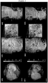
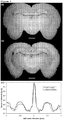
- the vertical sample arrangement also enabled a direct reconstruction of coronal slices through the sample, an approach very useful when trying to identify anatomical brain regions ( Fig. 3 ).
- the height of the sample was larger than the vertical height of the beam and therefore four scans have been collected along the vertical direction to image the whole brain.
- a qualitative comparison of the images clearly shows that the RP-reconstruction is as good as the one obtained with the PS-approach.
- a line profile taken at the level of the hippocampus see Fig. 3c , shows a quantitative good agreement between RP and PS approaches.
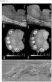
- the novel method has been validated using a more realistic sample, namely a specimen containing both soft and hard tissue.
- a more realistic sample namely a specimen containing both soft and hard tissue.
- the rat paw was also mounted vertically in order to best match the horizontal field of view of the detector. Seven stacked scans were necessary to image the full sample volume.
- the measurement of the rat paw was the most challenging experiment since the sample has been measured in air. This usually causes large phase jumps at the air-specimen interface and explains the "star" artifacts visible in Fig. 4b-1 and, less serious, in 4c-1.
- Our invention introduces a novel approach for fast and low dose extraction of both the absorption coefficient and the refractive index of a sample using a grating interferometer is introduced. It is demonstrated that this new approach yields comparable information to the established phase stepping technique but with a reduction factor of k /2 in the total dose delivered to the sample. Moreover, the reverse projection approach makes high-sensitivity phase contrast computed tomography (CT) as straightforward as conventional, absorption based CT. It is first shown that this new method works well with parallel beam geometries but it is not difficult to generalize it to either cone or fan beam setups, making it accessible also to X-ray tube-based applications.
- CT phase contrast computed tomography
- the significant decrease of the dose and the straight forward acquisition protocol does no affect image quality, while representing a major advancement in hard X-ray phase contrast tomography for synchrotron radiation and laboratory X-ray sources, enabling experiments impossible so far.
- Ring artifacts are clearly visible in Figure 5 , for both coronal (b1) and sagittal (b2) cuts. Due to the averaging effect associated to the phase stepping extraction, the PS-protocol is significantly less sensitive to grating defects and therefore the rings artifact are less pronounced, see Figure 5 a1-2.
Landscapes
- Health & Medical Sciences (AREA)
- Life Sciences & Earth Sciences (AREA)
- Engineering & Computer Science (AREA)
- Medical Informatics (AREA)
- Pathology (AREA)
- General Health & Medical Sciences (AREA)
- Physics & Mathematics (AREA)
- Nuclear Medicine, Radiotherapy & Molecular Imaging (AREA)
- Radiology & Medical Imaging (AREA)
- Heart & Thoracic Surgery (AREA)
- Veterinary Medicine (AREA)
- Biomedical Technology (AREA)
- High Energy & Nuclear Physics (AREA)
- Molecular Biology (AREA)
- Surgery (AREA)
- Animal Behavior & Ethology (AREA)
- Biophysics (AREA)
- Public Health (AREA)
- Optics & Photonics (AREA)
- Chemical & Material Sciences (AREA)
- Analytical Chemistry (AREA)
- Biochemistry (AREA)
- General Physics & Mathematics (AREA)
- Immunology (AREA)
- Analysing Materials By The Use Of Radiation (AREA)
- Apparatus For Radiation Diagnosis (AREA)
Claims (17)
- Installation d'imagerie pour la projection inverse dans le but d'obtenir des images radiologiques quantitatives avec des rayons X (durs) à partir d'un échantillon et pour extraire de manière quantitative à la fois des informations d'absorption et de phase à partir de l'échantillon, comprenant :a. un faisceau de rayons X généré par une source de rayons X ;b. un réseau de diviseurs de faisceaux (G1) et un réseau d'analyse espacés l'un de l'autre sur une distance D et dont les lignes respectives sont parallèles les unes aux autres ; dans lequel le réseau de diviseurs de faisceaux (G1) est un réseau linéaire et le réseau d'analyse est un réseau d'absorption linéaire avec une absorption élevée des rayons X, au moins un des réseaux (G1, G2) étant positionné par rapport à la sonde dans une direction (xg) essentiellement perpendiculaire à la fois au faisceau entrant et à l'orientation des lignes du réseau pour réaliser l'installation d'imagerie au centre de la zone linéaire de la courbe de translation
 c. un détecteur sensible à la position (PSD) comprenant une sensibilité de détection soumise à une modulation spatiale possédant un certain nombre de pixels individuels ;d. un moyen pour enregistrer les images du détecteur, dans lequel une série de M images sont récoltées, par la mise en rotation en continu ou en pas à pas de 0 à pi ou 2 pi, soit de l'échantillon, soit des réseaux (G1, G2), et de la source de rayons X par rapport à l'échantillon, dans lequel chaque image prise à un angle 0 ≤ Φ ≤ pi comprend une image de projection inverse correspondante prise à un angle pi ≤ Φ+pi ≤ 2 pi, pour obtenir au total un nombre de M/2 paires d'images spéculaires ;e. un moyen pour calculer en forme de pixels une image d'absorption M et une image de l'angle de réfraction θr à partir des paires d'images spéculaires - sans devoir procéder à un décalage de phase - conformément à :

- Installation d'imagerie selon la revendication 1, dans laquelle l'intensité I enregistrée par le PSD est exprimée sous la forme :


- Installation d'imagerie selon la revendication 1 ou 2, dans laquelle un réseau d'analyse possédant une structure de réseau unidimensionnelle (G2) avec un contraste élevé d'absorption des rayons X est placé devant le détecteur sensible à la position (PSD) et à proximité de ce dernier, avec ses lignes parallèles à celles du réseau de séparateurs de faisceaux (G1).
- Installation d'imagerie selon l'une quelconque des revendications précédentes, dans laquelle un réseau d'analyse possédant une structure de réseau unidimensionnelle avec un contraste élevé d'absorption des rayons X, sa période étant la même que celle de la propre image du réseau de séparateurs de faisceaux (G1), est placé devant le détecteur sensible à la position (PSD) et à proximité de ce dernier, avec ses lignes parallèles à celles du réseau de séparateurs de faisceaux (G1).
- Installation d'imagerie selon l'une quelconque des revendications précédentes, dans laquelle la distance (D) entre le réseau de séparateurs de faisceaux (G1) et le réseau d'analyse (G2) est choisie pour représenter une distance fractionnaire impaire de Talbot, fournie par l'équation


- Installation d'imagerie selon l'une quelconque des revendications précédentes, dans laquelle le réseau de séparateurs de faisceaux (G1) est un réseau de phase linéaire avec une faible absorption des rayons X, mais avec un décalage de phase considérable des rayons X (Φ), ce dernier étant de préférence égal à


- Installation d'imagerie selon l'une quelconque des revendications précédentes, dans laquelle lorsque le réseau de séparateurs de faisceaux (G1) est un réseau de phase linéaire avec une faible absorption des rayons X, on l'obtient par gravure profonde dans du silicium, dans un polymère ou dans des matières similaires.
- Installation d'imagerie selon l'une quelconque des revendications précédentes, dans laquelle le réseau d'analyse (G2) est, soit placé devant le détecteur sensible à la position (PSD) et à proximité de ce dernier, soit intégré avec sa structure de réseau unidimensionnelle dans le détecteur, la dimension des pixels du détecteur étant de 2 à 10 fois supérieure à la dimension de la période du réseau, des demi lignes avec détecteur dans un pixel étant sensibles aux rayons X et des demi lignes sans détecteur laissant passer les rayons X.
- Installation d'imagerie selon l'une quelconque des revendications précédentes, dans laquelle un collimateur placé entre la source de rayons X et le réseau de séparateurs de faisceaux (G1) limite l'étendue spatiale des rayons X d'éclairage à un faisceau en éventail, un détecteur de réseau linéaire est utilisé, et un mécanisme est inclus qui permet la rotation (que ce soit en pas à pas ou en continu) de l'échantillon par rapport au reste de l'appareil, l'axe de rotation étant perpendiculaire à l'angle d'ouverture de l'éventail, et de préférence qui permet en même temps la translation (que ce soit en pas à pas ou en continu) de l'échantillon par rapport au reste de l'appareil dans la direction parallèle à l'axe de rotation.
- Procédé pour la projection inverse dans le but d'obtenir des images radiologiques quantitatives avec des rayons X (durs) à partir d'un échantillon et pour extraire de manière quantitative à la fois des informations d'absorption et de phase à partir de l'échantillon, comprenant les étapes dans lesquelles :a. on procure une source de rayons X (rayons X) ;b. on procure un réseau de diviseurs de faisceaux (G1) et un réseau d'analyse (G2) espacés l'un de l'autre sur une distance D et dont les lignes respectives sont parallèles les unes aux autres ; dans lequel le réseau de diviseurs de faisceaux (G1) est un réseau linéaire, soit un réseau d'absorption avec une absorption élevée des rayons X, soit un réseau de phase avec une faible absorption des rayons X, et le réseau d'analyse (G2) est un réseau d'absorption linéaire avec une absorption élevée des rayons X ;c. on procure un détecteur sensible à la position (PSD) comprenant une sensibilité de détection soumise à une modulation spatiale possédant un certain nombre de pixels individuels ;d. on positionne au moins un des réseaux, tels que G1 et G2, par rapport à la sonde dans une direction (xg) essentiellement perpendiculaire à la fois au faisceau entrant et à l'orientation des lignes des réseaux pour réaliser l'installation d'imagerie au centre de la zone linéaire de la courbe de translation
 e. on place l'échantillon faisant l'objet de la recherche, soit entre la source des rayons X et le réseau de diviseurs de faisceaux (G1), soit entre le réseau de diviseurs de faisceaux (G1) et le réseau d'analyse (G2) ; on applique des clichés de la source des rayons X sur l'échantillon et on enregistre les images du détecteur (PSD) ;f. on enregistre les images du détecteur, en récoltant une série de M images, par la mise en rotation en continu ou en pas à pas de 0 à pi ou 2 pi, soit de l'échantillon, soit des réseaux (G0, G1, G2), et de la source de rayons X par rapport à l'échantillon, dans lequel chaque image prise à un angle 0 ≤ Φ ≤ pi comprend une image de projection inverse correspondante prise à un angle pi ≤ Φ+pi ≤ 2 pi, pour obtenir au total un nombre de M/2 paires d'images spéculaires ;g. on utilise un moyen pour calculer en forme de pixels une image d'absorption M et une image de l'angle de réfraction θr à partir des paires d'images - sans devoir procéder à un décalage de phase - conformément à :

- Procédé selon la revendication 10, dans lequel, lorsque le réseau de séparateurs de faisceaux (G1) est un réseau de phase linéaire avec une faible absorption des rayons X, l'épaisseur des lignes du réseau manifesteront un décalage de phase considérable des rayons X (Φ), ce dernier étant de préférence égal à


- Procédé selon la revendication 10 ou 11, dans lequel, lorsque le réseau de séparateurs de faisceaux (G1) est un réseau de phase linéaire avec une faible absorption des rayons X, on l'obtient par gravure profonde dans du silicium, dans un polymère ou dans une matière similaire.
- Procédé selon l'une quelconque des revendications 10 à 12, dans lequel un réseau d'analyse (G2) possédant une structure de réseau unidimensionnelle avec un contraste élevé d'absorption des rayons X, sa période étant la même que celle de l'image du réseau de séparateurs de faisceaux, est placé devant le détecteur sensible à la position (PSD) et à proximité de ce dernier, avec ses lignes parallèles à celles du réseau de phase ; de préférence, cette structure de réseau fait office de grille antidiffusion ou bien on utilise une grille antidiffusion pour faire office de masque de modulation.
- Procédé selon l'une quelconque des revendications 10 à 13, dans lequel la distance entre le séparateur de faisceaux et l'analyseur est choisie pour représenter une distance fractionnaire impaire de Talbot, fournie par l'équation


- Procédé selon l'une quelconque des revendications 10 à 14, dans lequel un collimateur placé entre la source et le réseau de séparateurs de faisceaux (G1) limite l'étendue spatiale des rayons X d'éclairage à un faisceau en éventail, un détecteur de réseau linéaire est utilisé, et un mécanisme est compris qui permet la rotation (que ce soit en pas à pas ou en continu) de l'échantillon par rapport au reste de l'appareil, l'axe de rotation étant perpendiculaire à l'angle d'ouverture de l'éventail, et de préférence qui permet en même temps la translation (que ce soit en pas à pas ou en continu) de l'échantillon par rapport au reste de l'appareil dans la direction parallèle à l'axe de rotation.
- Procédé selon l'une quelconque des revendications 10 à 15, dans lequel un collimateur placé entre la source et le réseau de séparateurs de faisceaux (G1) limite l'étendue spatiale des rayons X d'éclairage à un faisceau de forme conique, un détecteur de réseau de pixels est utilisé, et un mécanisme est compris qui permet la rotation de l'échantillon par rapport au reste de l'appareil, perpendiculairement à l'angle d'ouverture de l'éventail.
- Procédé selon l'une quelconque des revendications 10 à 16, dans lequel le réseau d'analyse (G2) est, soit placé devant le détecteur sensible à la position (PSD) et à proximité de ce dernier, soit intégré avec sa structure de réseau unidimensionnelle dans le détecteur, la dimension des pixels du détecteur étant de 2 à 10 fois supérieure à la dimension de la période du réseau, des demi lignes avec détecteur dans un pixel étant sensibles aux rayons X et des demi lignes sans détecteur laissant passer les rayons X.
Priority Applications (1)
| Application Number | Priority Date | Filing Date | Title |
|---|---|---|---|
| EP10703260.9A EP2400891B1 (fr) | 2009-02-05 | 2010-02-03 | Procédé d'imagerie par contraste de phase aux rayons x, fondé sur des réseaux de diffraction, en une seule étape et n'exigeant que de faibles doses |
Applications Claiming Priority (3)
| Application Number | Priority Date | Filing Date | Title |
|---|---|---|---|
| EP09100099 | 2009-02-05 | ||
| PCT/EP2010/051291 WO2010089319A1 (fr) | 2009-02-05 | 2010-02-03 | Procédé d'imagerie par contraste de phase aux rayons x, fondé sur des réseaux de diffraction, en une seule étape et n'exigeant que de faibles doses |
| EP10703260.9A EP2400891B1 (fr) | 2009-02-05 | 2010-02-03 | Procédé d'imagerie par contraste de phase aux rayons x, fondé sur des réseaux de diffraction, en une seule étape et n'exigeant que de faibles doses |
Publications (2)
| Publication Number | Publication Date |
|---|---|
| EP2400891A1 EP2400891A1 (fr) | 2012-01-04 |
| EP2400891B1 true EP2400891B1 (fr) | 2017-07-19 |
Family
ID=42078937
Family Applications (1)
| Application Number | Title | Priority Date | Filing Date |
|---|---|---|---|
| EP10703260.9A Active EP2400891B1 (fr) | 2009-02-05 | 2010-02-03 | Procédé d'imagerie par contraste de phase aux rayons x, fondé sur des réseaux de diffraction, en une seule étape et n'exigeant que de faibles doses |
Country Status (7)
| Country | Link |
|---|---|
| US (1) | US8972191B2 (fr) |
| EP (1) | EP2400891B1 (fr) |
| JP (1) | JP5606455B2 (fr) |
| CN (1) | CN102325498B (fr) |
| AU (1) | AU2010210169B2 (fr) |
| CA (1) | CA2751442C (fr) |
| WO (1) | WO2010089319A1 (fr) |
Families Citing this family (61)
| Publication number | Priority date | Publication date | Assignee | Title |
|---|---|---|---|---|
| EP2652708B1 (fr) | 2010-12-13 | 2015-01-28 | Paul Scherrer Institut | Procédé et système permettant une intégration d'image à l'aide d'une optimisation sous contraintes pour une imagerie par contraste de phase avec un agencement de réseaux |
| JP2012130586A (ja) * | 2010-12-22 | 2012-07-12 | Fujifilm Corp | 放射線画像検出装置、放射線撮影装置、及び放射線撮影システム |
| JP2012157690A (ja) * | 2011-01-14 | 2012-08-23 | Fujifilm Corp | 放射線画像撮影装置および放射線画像検出器 |
| EP2713884B1 (fr) * | 2011-06-01 | 2019-07-31 | Total SA | Dispositif de tomographie à rayons x |
| BR112013030647A2 (pt) | 2011-06-01 | 2016-11-29 | Total Sa | dispositivo de tomografia de raios x |
| AU2012288992B2 (en) * | 2011-07-28 | 2015-03-12 | Paul Scherrer Institut | Method for image fusion based on principal component analysis |
| US20150117599A1 (en) * | 2013-10-31 | 2015-04-30 | Sigray, Inc. | X-ray interferometric imaging system |
| BR112014017853A8 (pt) * | 2012-01-24 | 2017-07-11 | Koninklijke Philips Nv | Sistema de geração de imagens por raios x para a geração de imagens de contraste de fase de um objeto, método para a geração de imagens por de contraste de fase de raios x de um objeto, elemento de programa de computador para o controle de um aparelho, e meio legível por computador |
| WO2013124164A1 (fr) * | 2012-02-24 | 2013-08-29 | Paul Scherrer Institut | Système non-invasif de classification de différents types de micro - calcifications dans des tissus humains |
| US9357975B2 (en) | 2013-12-30 | 2016-06-07 | Carestream Health, Inc. | Large FOV phase contrast imaging based on detuned configuration including acquisition and reconstruction techniques |
| US10578563B2 (en) | 2012-12-21 | 2020-03-03 | Carestream Health, Inc. | Phase contrast imaging computed tomography scanner |
| US10096098B2 (en) | 2013-12-30 | 2018-10-09 | Carestream Health, Inc. | Phase retrieval from differential phase contrast imaging |
| KR102060659B1 (ko) * | 2013-03-20 | 2019-12-30 | 삼성전자주식회사 | 영상 처리를 위한 투사 및 역투사 방법 및 그 영상 처리 장치 |
| EP2978377B1 (fr) * | 2013-03-26 | 2021-05-05 | Institute of Experimental and Applied Physics | Méthode de radiographie à gradient de phase et agencement de système d'imagerie pour l'application de la méthode |
| CN103164863B (zh) * | 2013-04-02 | 2016-03-02 | 中国科学院高能物理研究所 | 用于重建正电子发射计算机断层成像图像的方法 |
| WO2014180901A1 (fr) | 2013-05-10 | 2014-11-13 | Siemens Aktiengesellschaft | Dispositif d'imagerie radiographique à contraste de phase et réseau de réfraction pour un tel dispositif |
| US9763634B2 (en) | 2013-05-22 | 2017-09-19 | Siemens Aktiengesellschaft | Phase-contrast X-ray imaging device |
| US10295485B2 (en) | 2013-12-05 | 2019-05-21 | Sigray, Inc. | X-ray transmission spectrometer system |
| US10297359B2 (en) | 2013-09-19 | 2019-05-21 | Sigray, Inc. | X-ray illumination system with multiple target microstructures |
| US10269528B2 (en) | 2013-09-19 | 2019-04-23 | Sigray, Inc. | Diverging X-ray sources using linear accumulation |
| US10304580B2 (en) | 2013-10-31 | 2019-05-28 | Sigray, Inc. | Talbot X-ray microscope |
| USRE48612E1 (en) | 2013-10-31 | 2021-06-29 | Sigray, Inc. | X-ray interferometric imaging system |
| US9719947B2 (en) * | 2013-10-31 | 2017-08-01 | Sigray, Inc. | X-ray interferometric imaging system |
| JP2015118081A (ja) * | 2013-11-12 | 2015-06-25 | キヤノン株式会社 | 放射線検出システムおよび放射線撮像装置 |
| WO2015122542A1 (fr) * | 2014-02-14 | 2015-08-20 | Canon Kabushiki Kaisha | Interféromètre de talbot à rayons x et système d'interféromètre de talbot à rayons x |
| CN106104318B (zh) * | 2014-04-09 | 2019-05-03 | 拉姆伯斯公司 | 低功率图像改变检测器 |
| CN103900502B (zh) * | 2014-04-16 | 2017-01-04 | 中国科学技术大学 | 基于x射线几何投影莫尔条纹的精密位移测量装置及方法 |
| US10401309B2 (en) | 2014-05-15 | 2019-09-03 | Sigray, Inc. | X-ray techniques using structured illumination |
| EP3143384B1 (fr) * | 2014-05-15 | 2020-03-04 | Sigray Inc. | Système et procédé au rayons x pour la mesure, la caractérisation et l'analyse de structures periodiques |
| JP2016106721A (ja) * | 2014-12-03 | 2016-06-20 | キヤノン株式会社 | 画像処理装置および画像処理方法 |
| US10352880B2 (en) | 2015-04-29 | 2019-07-16 | Sigray, Inc. | Method and apparatus for x-ray microscopy |
| WO2016207423A1 (fr) * | 2015-06-26 | 2016-12-29 | Koninklijke Philips N.V. | Reconstruction robuste pour tomographie par ordinateur en champ sombre et à contraste de phase |
| US10295486B2 (en) | 2015-08-18 | 2019-05-21 | Sigray, Inc. | Detector for X-rays with high spatial and high spectral resolution |
| CN105675631A (zh) * | 2016-01-05 | 2016-06-15 | 合肥泰禾光电科技股份有限公司 | 一种快速扇束几何相位衬度ct成像装置和方法 |
| CN107807139B (zh) * | 2016-09-05 | 2020-04-24 | 天津工业大学 | 一种无步进装置的双能x射线相衬成像系统及其实现方法 |
| US10247683B2 (en) | 2016-12-03 | 2019-04-02 | Sigray, Inc. | Material measurement techniques using multiple X-ray micro-beams |
| CN106618623B (zh) * | 2017-01-11 | 2019-08-30 | 合肥工业大学 | 一次曝光的硬x射线光栅干涉仪的成像方法 |
| WO2018144705A1 (fr) | 2017-02-01 | 2018-08-09 | Washington University | Procédé à un coup pour tomographie à contraste de phases à rayons x à éclairage par les bords |
| JP6937380B2 (ja) | 2017-03-22 | 2021-09-22 | シグレイ、インコーポレイテッド | X線分光を実施するための方法およびx線吸収分光システム |
| JP6943090B2 (ja) * | 2017-09-05 | 2021-09-29 | 株式会社島津製作所 | X線イメージング装置 |
| EP3494885A1 (fr) * | 2017-12-07 | 2019-06-12 | Koninklijke Philips N.V. | Appareil de présentation d'informations d'image à rayons x de champ sombre |
| US10578566B2 (en) | 2018-04-03 | 2020-03-03 | Sigray, Inc. | X-ray emission spectrometer system |
| US10989822B2 (en) | 2018-06-04 | 2021-04-27 | Sigray, Inc. | Wavelength dispersive x-ray spectrometer |
| GB2591630B (en) | 2018-07-26 | 2023-05-24 | Sigray Inc | High brightness x-ray reflection source |
| US10656105B2 (en) | 2018-08-06 | 2020-05-19 | Sigray, Inc. | Talbot-lau x-ray source and interferometric system |
| US10962491B2 (en) | 2018-09-04 | 2021-03-30 | Sigray, Inc. | System and method for x-ray fluorescence with filtering |
| DE112019004478T5 (de) | 2018-09-07 | 2021-07-08 | Sigray, Inc. | System und verfahren zur röntgenanalyse mit wählbarer tiefe |
| CN110095481B (zh) * | 2019-05-24 | 2021-03-05 | 清华大学 | X射线光栅成像系统与成像方法 |
| WO2021046059A1 (fr) | 2019-09-03 | 2021-03-11 | Sigray, Inc. | Système et procédé pour imagerie de laminographie calculée par fluorescence de rayons x |
| CN110916712B (zh) * | 2019-11-29 | 2022-04-29 | 清华大学 | 光栅成像系统及其扫描方法 |
| CN110916713B (zh) * | 2019-11-29 | 2022-04-29 | 清华大学 | 光栅成像系统及其扫描方法 |
| NL2024368B1 (en) * | 2019-12-03 | 2021-08-31 | Xeikon Prepress Nv | Method and system for processing a raster image file |
| US11175243B1 (en) | 2020-02-06 | 2021-11-16 | Sigray, Inc. | X-ray dark-field in-line inspection for semiconductor samples |
| US11215572B2 (en) | 2020-05-18 | 2022-01-04 | Sigray, Inc. | System and method for x-ray absorption spectroscopy using a crystal analyzer and a plurality of detector elements |
| US11549895B2 (en) | 2020-09-17 | 2023-01-10 | Sigray, Inc. | System and method using x-rays for depth-resolving metrology and analysis |
| US11686692B2 (en) | 2020-12-07 | 2023-06-27 | Sigray, Inc. | High throughput 3D x-ray imaging system using a transmission x-ray source |
| CN112568923B (zh) * | 2020-12-10 | 2022-08-19 | 中国科学院深圳先进技术研究院 | X射线相位衬度图像提取方法、装置、终端及存储介质 |
| CN113237901A (zh) * | 2021-05-07 | 2021-08-10 | 中国科学院上海应用物理研究所 | 一种生物特征识别系统及生物特征识别方法 |
| CN114137002B (zh) * | 2021-11-18 | 2023-07-14 | 北京航空航天大学 | 一种基于衬度间增强的低剂量x射线差分相位衬度成像方法 |
| US11885755B2 (en) | 2022-05-02 | 2024-01-30 | Sigray, Inc. | X-ray sequential array wavelength dispersive spectrometer |
| CN115684222B (zh) * | 2022-12-21 | 2023-04-11 | 济南汉江光电科技有限公司 | 一种快速低剂量的x射线多模态ct系统及成像方法 |
Family Cites Families (14)
| Publication number | Priority date | Publication date | Assignee | Title |
|---|---|---|---|---|
| JP2000098449A (ja) | 1998-09-21 | 2000-04-07 | Canon Inc | 露出制御装置及び露出制御方法及び電子カメラ |
| JP2003135438A (ja) * | 2001-11-02 | 2003-05-13 | Fuji Photo Film Co Ltd | 画像生成方法および装置並びにプログラム |
| JP2004203066A (ja) | 2002-12-24 | 2004-07-22 | Kobe Steel Ltd | 自動車のバンパー装置 |
| ATE502325T1 (de) | 2004-10-22 | 2011-04-15 | Eulitha Ag | System und verfahren zum erzeugen eines periodischen und/oder fastperiodischen musters auf einer probe |
| EP1731099A1 (fr) | 2005-06-06 | 2006-12-13 | Paul Scherrer Institut | Interféromètre pour l'imagerie et la tomographie à contraste de phase avec une source de rayons X incohérente et polychromatique |
| CN101013613B (zh) * | 2006-02-01 | 2011-10-19 | 西门子公司 | X射线设备的焦点-检测器装置的x射线光学透射光栅 |
| DE102006017290B4 (de) | 2006-02-01 | 2017-06-22 | Siemens Healthcare Gmbh | Fokus/Detektor-System einer Röntgenapparatur, Röntgen-System und Verfahren zur Erzeugung von Phasenkontrastaufnahmen |
| DE102006037281A1 (de) | 2006-02-01 | 2007-08-09 | Siemens Ag | Röntgenoptisches Durchstrahlungsgitter einer Fokus-Detektor-Anordnung einer Röntgenapparatur zur Erzeugung projektiver oder tomographischer Phasenkontrastaufnahmen von einem Untersuchungsobjekt |
| DE102006063048B3 (de) | 2006-02-01 | 2018-03-29 | Siemens Healthcare Gmbh | Fokus/Detektor-System einer Röntgenapparatur zur Erzeugung von Phasenkontrastaufnahmen |
| EP1879020A1 (fr) | 2006-07-12 | 2008-01-16 | Paul Scherrer Institut | Interféromètre par rayons X pour l'imagerie à contraste de phase |
| JP5273955B2 (ja) * | 2007-06-26 | 2013-08-28 | 株式会社日立製作所 | X線撮像装置及びx線撮像方法 |
| WO2009076700A1 (fr) * | 2007-12-14 | 2009-06-25 | Commonwealth Scientific And Industrial Research Organisation | Procédé et appareil d'imagerie à contraste de phase |
| US7949095B2 (en) * | 2009-03-02 | 2011-05-24 | University Of Rochester | Methods and apparatus for differential phase-contrast fan beam CT, cone-beam CT and hybrid cone-beam CT |
| US8760817B2 (en) * | 2009-05-22 | 2014-06-24 | HGST Netherlands B.V. | Three-terminal design for spin accumulation magnetic sensor |
-
2010
- 2010-02-03 AU AU2010210169A patent/AU2010210169B2/en not_active Ceased
- 2010-02-03 EP EP10703260.9A patent/EP2400891B1/fr active Active
- 2010-02-03 JP JP2011548673A patent/JP5606455B2/ja not_active Expired - Fee Related
- 2010-02-03 CN CN2010800066507A patent/CN102325498B/zh not_active Expired - Fee Related
- 2010-02-03 US US13/148,198 patent/US8972191B2/en active Active
- 2010-02-03 CA CA2751442A patent/CA2751442C/fr not_active Expired - Fee Related
- 2010-02-03 WO PCT/EP2010/051291 patent/WO2010089319A1/fr active Application Filing
Non-Patent Citations (1)
| Title |
|---|
| None * |
Also Published As
| Publication number | Publication date |
|---|---|
| JP2012516739A (ja) | 2012-07-26 |
| CA2751442C (fr) | 2018-06-12 |
| US20120041679A1 (en) | 2012-02-16 |
| JP5606455B2 (ja) | 2014-10-15 |
| CN102325498A (zh) | 2012-01-18 |
| AU2010210169B2 (en) | 2015-04-09 |
| CN102325498B (zh) | 2013-07-10 |
| WO2010089319A1 (fr) | 2010-08-12 |
| CA2751442A1 (fr) | 2010-08-12 |
| US8972191B2 (en) | 2015-03-03 |
| AU2010210169A1 (en) | 2011-08-25 |
| EP2400891A1 (fr) | 2012-01-04 |
Similar Documents
| Publication | Publication Date | Title |
|---|---|---|
| EP2400891B1 (fr) | Procédé d'imagerie par contraste de phase aux rayons x, fondé sur des réseaux de diffraction, en une seule étape et n'exigeant que de faibles doses | |
| EP2652708B1 (fr) | Procédé et système permettant une intégration d'image à l'aide d'une optimisation sous contraintes pour une imagerie par contraste de phase avec un agencement de réseaux | |
| US10058300B2 (en) | Large FOV phase contrast imaging based on detuned configuration including acquisition and reconstruction techniques | |
| EP2586373B1 (fr) | Interféromètre à rayons X | |
| US9494534B2 (en) | Material differentiation with phase contrast imaging | |
| US8855265B2 (en) | Correction method for differential phase contrast imaging | |
| Vila-Comamala et al. | High sensitivity X-ray phase contrast imaging by laboratory grating-based interferometry at high Talbot order geometry | |
| Wen et al. | Subnanoradian X-ray phase-contrast imaging using a far-field interferometer of nanometric phase gratings | |
| Stampanoni et al. | Tomographic hard X‐ray phase contrast micro‐and nano‐imaging at TOMCAT | |
| JP5665834B2 (ja) | X線撮像装置 | |
| David et al. | Hard X-ray phase imaging and tomography using a grating interferometer | |
| Thüring et al. | Compact hard x-ray grating interferometry for table top phase contrast micro CT | |
| Vittoria et al. | Retrieving the ultrasmall-angle X-ray scattering signal with polychromatic radiation in speckle-tracking and beam-tracking phase-contrast imaging | |
| Savatović et al. | Multi-resolution X-ray phase-contrast and dark-field tomography of human cerebellum with near-field speckles | |
| JP6788521B2 (ja) | X線撮像装置 | |
| Balles et al. | Quantitative phase contrast and X-ray scattering micro-tomography with the 9.2 keV liquid metal jet anode: Applications on materials and life science | |
| Robisch et al. | Nanoscale x-ray holo-tomography of human brain tissue with phase retrieval based on multiphoton energy recordings | |
| Pyakurel | Phase and dark field radiography and CT with mesh-based structured illumination and polycapillary optics | |
| Zdora et al. | Principles and State of the Art of X-ray Speckle-Based Imaging | |
| Liu et al. | A comparative study of X-ray phase micro-tomography: Grating based technique vs. high-energy propagation based technique | |
| Bopp et al. | X-ray Phase Contrast: Research on a Future Imaging Modality | |
| Vittoria et al. | Retrieving the signal from ultra-small-angle x-ray scattering with polychromatic radiation in speckle-tracking and beam-tracking phase-contrast imaging | |
| Pyakurel et al. | Optimization of Signal and Noise in X-Ray Phase and Dark Field Imaging with a Wire Mesh | |
| Han et al. | Developments of x-ray grating imaging and trying of multiple information fusion | |
| Li et al. | Developments of X-Ray Grating Imaging Technology |
Legal Events
| Date | Code | Title | Description |
|---|---|---|---|
| PUAI | Public reference made under article 153(3) epc to a published international application that has entered the european phase |
Free format text: ORIGINAL CODE: 0009012 |
|
| 17P | Request for examination filed |
Effective date: 20110720 |
|
| AK | Designated contracting states |
Kind code of ref document: A1 Designated state(s): AT BE BG CH CY CZ DE DK EE ES FI FR GB GR HR HU IE IS IT LI LT LU LV MC MK MT NL NO PL PT RO SE SI SK SM TR |
|
| DAX | Request for extension of the european patent (deleted) | ||
| GRAP | Despatch of communication of intention to grant a patent |
Free format text: ORIGINAL CODE: EPIDOSNIGR1 |
|
| INTG | Intention to grant announced |
Effective date: 20170209 |
|
| GRAS | Grant fee paid |
Free format text: ORIGINAL CODE: EPIDOSNIGR3 |
|
| GRAA | (expected) grant |
Free format text: ORIGINAL CODE: 0009210 |
|
| AK | Designated contracting states |
Kind code of ref document: B1 Designated state(s): AT BE BG CH CY CZ DE DK EE ES FI FR GB GR HR HU IE IS IT LI LT LU LV MC MK MT NL NO PL PT RO SE SI SK SM TR |
|
| REG | Reference to a national code |
Ref country code: GB Ref legal event code: FG4D |
|
| REG | Reference to a national code |
Ref country code: CH Ref legal event code: EP |
|
| REG | Reference to a national code |
Ref country code: IE Ref legal event code: FG4D |
|
| REG | Reference to a national code |
Ref country code: AT Ref legal event code: REF Ref document number: 909566 Country of ref document: AT Kind code of ref document: T Effective date: 20170815 |
|
| REG | Reference to a national code |
Ref country code: DE Ref legal event code: R096 Ref document number: 602010043704 Country of ref document: DE |
|
| REG | Reference to a national code |
Ref country code: CH Ref legal event code: NV Representative=s name: SIEMENS SCHWEIZ AG, CH |
|
| REG | Reference to a national code |
Ref country code: NL Ref legal event code: FP |
|
| REG | Reference to a national code |
Ref country code: LT Ref legal event code: MG4D |
|
| PG25 | Lapsed in a contracting state [announced via postgrant information from national office to epo] |
Ref country code: NO Free format text: LAPSE BECAUSE OF FAILURE TO SUBMIT A TRANSLATION OF THE DESCRIPTION OR TO PAY THE FEE WITHIN THE PRESCRIBED TIME-LIMIT Effective date: 20171019 Ref country code: SE Free format text: LAPSE BECAUSE OF FAILURE TO SUBMIT A TRANSLATION OF THE DESCRIPTION OR TO PAY THE FEE WITHIN THE PRESCRIBED TIME-LIMIT Effective date: 20170719 Ref country code: HR Free format text: LAPSE BECAUSE OF FAILURE TO SUBMIT A TRANSLATION OF THE DESCRIPTION OR TO PAY THE FEE WITHIN THE PRESCRIBED TIME-LIMIT Effective date: 20170719 Ref country code: LT Free format text: LAPSE BECAUSE OF FAILURE TO SUBMIT A TRANSLATION OF THE DESCRIPTION OR TO PAY THE FEE WITHIN THE PRESCRIBED TIME-LIMIT Effective date: 20170719 Ref country code: FI Free format text: LAPSE BECAUSE OF FAILURE TO SUBMIT A TRANSLATION OF THE DESCRIPTION OR TO PAY THE FEE WITHIN THE PRESCRIBED TIME-LIMIT Effective date: 20170719 |
|
| REG | Reference to a national code |
Ref country code: FR Ref legal event code: PLFP Year of fee payment: 9 |
|
| PG25 | Lapsed in a contracting state [announced via postgrant information from national office to epo] |
Ref country code: GR Free format text: LAPSE BECAUSE OF FAILURE TO SUBMIT A TRANSLATION OF THE DESCRIPTION OR TO PAY THE FEE WITHIN THE PRESCRIBED TIME-LIMIT Effective date: 20171020 Ref country code: PL Free format text: LAPSE BECAUSE OF FAILURE TO SUBMIT A TRANSLATION OF THE DESCRIPTION OR TO PAY THE FEE WITHIN THE PRESCRIBED TIME-LIMIT Effective date: 20170719 Ref country code: ES Free format text: LAPSE BECAUSE OF FAILURE TO SUBMIT A TRANSLATION OF THE DESCRIPTION OR TO PAY THE FEE WITHIN THE PRESCRIBED TIME-LIMIT Effective date: 20170719 Ref country code: BG Free format text: LAPSE BECAUSE OF FAILURE TO SUBMIT A TRANSLATION OF THE DESCRIPTION OR TO PAY THE FEE WITHIN THE PRESCRIBED TIME-LIMIT Effective date: 20171019 Ref country code: IS Free format text: LAPSE BECAUSE OF FAILURE TO SUBMIT A TRANSLATION OF THE DESCRIPTION OR TO PAY THE FEE WITHIN THE PRESCRIBED TIME-LIMIT Effective date: 20171119 Ref country code: LV Free format text: LAPSE BECAUSE OF FAILURE TO SUBMIT A TRANSLATION OF THE DESCRIPTION OR TO PAY THE FEE WITHIN THE PRESCRIBED TIME-LIMIT Effective date: 20170719 |
|
| REG | Reference to a national code |
Ref country code: DE Ref legal event code: R097 Ref document number: 602010043704 Country of ref document: DE |
|
| PG25 | Lapsed in a contracting state [announced via postgrant information from national office to epo] |
Ref country code: DK Free format text: LAPSE BECAUSE OF FAILURE TO SUBMIT A TRANSLATION OF THE DESCRIPTION OR TO PAY THE FEE WITHIN THE PRESCRIBED TIME-LIMIT Effective date: 20170719 Ref country code: CZ Free format text: LAPSE BECAUSE OF FAILURE TO SUBMIT A TRANSLATION OF THE DESCRIPTION OR TO PAY THE FEE WITHIN THE PRESCRIBED TIME-LIMIT Effective date: 20170719 Ref country code: RO Free format text: LAPSE BECAUSE OF FAILURE TO SUBMIT A TRANSLATION OF THE DESCRIPTION OR TO PAY THE FEE WITHIN THE PRESCRIBED TIME-LIMIT Effective date: 20170719 |
|
| PLBE | No opposition filed within time limit |
Free format text: ORIGINAL CODE: 0009261 |
|
| STAA | Information on the status of an ep patent application or granted ep patent |
Free format text: STATUS: NO OPPOSITION FILED WITHIN TIME LIMIT |
|
| PG25 | Lapsed in a contracting state [announced via postgrant information from national office to epo] |
Ref country code: SM Free format text: LAPSE BECAUSE OF FAILURE TO SUBMIT A TRANSLATION OF THE DESCRIPTION OR TO PAY THE FEE WITHIN THE PRESCRIBED TIME-LIMIT Effective date: 20170719 Ref country code: SK Free format text: LAPSE BECAUSE OF FAILURE TO SUBMIT A TRANSLATION OF THE DESCRIPTION OR TO PAY THE FEE WITHIN THE PRESCRIBED TIME-LIMIT Effective date: 20170719 Ref country code: EE Free format text: LAPSE BECAUSE OF FAILURE TO SUBMIT A TRANSLATION OF THE DESCRIPTION OR TO PAY THE FEE WITHIN THE PRESCRIBED TIME-LIMIT Effective date: 20170719 |
|
| 26N | No opposition filed |
Effective date: 20180420 |
|
| PG25 | Lapsed in a contracting state [announced via postgrant information from national office to epo] |
Ref country code: SI Free format text: LAPSE BECAUSE OF FAILURE TO SUBMIT A TRANSLATION OF THE DESCRIPTION OR TO PAY THE FEE WITHIN THE PRESCRIBED TIME-LIMIT Effective date: 20170719 |
|
| PG25 | Lapsed in a contracting state [announced via postgrant information from national office to epo] |
Ref country code: MC Free format text: LAPSE BECAUSE OF FAILURE TO SUBMIT A TRANSLATION OF THE DESCRIPTION OR TO PAY THE FEE WITHIN THE PRESCRIBED TIME-LIMIT Effective date: 20170719 |
|
| REG | Reference to a national code |
Ref country code: IE Ref legal event code: MM4A |
|
| PG25 | Lapsed in a contracting state [announced via postgrant information from national office to epo] |
Ref country code: LU Free format text: LAPSE BECAUSE OF NON-PAYMENT OF DUE FEES Effective date: 20180203 |
|
| PG25 | Lapsed in a contracting state [announced via postgrant information from national office to epo] |
Ref country code: IE Free format text: LAPSE BECAUSE OF NON-PAYMENT OF DUE FEES Effective date: 20180203 |
|
| REG | Reference to a national code |
Ref country code: AT Ref legal event code: UEP Ref document number: 909566 Country of ref document: AT Kind code of ref document: T Effective date: 20170719 |
|
| REG | Reference to a national code |
Ref country code: CH Ref legal event code: PUEA Owner name: PAUL SCHERRER INSTITUT, CH Free format text: FORMER OWNER: PAUL SCHERRER INSTITUT, CN |
|
| REG | Reference to a national code |
Ref country code: DE Ref legal event code: R082 Ref document number: 602010043704 Country of ref document: DE Representative=s name: FISCHER, MICHAEL, DR., DE Ref country code: DE Ref legal event code: R081 Ref document number: 602010043704 Country of ref document: DE Owner name: PAUL SCHERRER INSTITUT, CH Free format text: FORMER OWNERS: INSTITUTE OF HIGH ENERGY PHYSICS, BEIJING, CN; PAUL SCHERRER INSTITUT, VILLIGEN, CH |
|
| REG | Reference to a national code |
Ref country code: GB Ref legal event code: 732E Free format text: REGISTERED BETWEEN 20190912 AND 20190918 |
|
| REG | Reference to a national code |
Ref country code: BE Ref legal event code: PD Owner name: PAUL SCHERRER INSTITUT; CH Free format text: DETAILS ASSIGNMENT: CHANGE OF OWNER(S), CESSION Effective date: 20190917 |
|
| REG | Reference to a national code |
Ref country code: AT Ref legal event code: PC Ref document number: 909566 Country of ref document: AT Kind code of ref document: T Owner name: PAUL SCHERRER INSTITUT, CH Effective date: 20191017 |
|
| PG25 | Lapsed in a contracting state [announced via postgrant information from national office to epo] |
Ref country code: MT Free format text: LAPSE BECAUSE OF NON-PAYMENT OF DUE FEES Effective date: 20180203 |
|
| PG25 | Lapsed in a contracting state [announced via postgrant information from national office to epo] |
Ref country code: TR Free format text: LAPSE BECAUSE OF FAILURE TO SUBMIT A TRANSLATION OF THE DESCRIPTION OR TO PAY THE FEE WITHIN THE PRESCRIBED TIME-LIMIT Effective date: 20170719 |
|
| PG25 | Lapsed in a contracting state [announced via postgrant information from national office to epo] |
Ref country code: PT Free format text: LAPSE BECAUSE OF FAILURE TO SUBMIT A TRANSLATION OF THE DESCRIPTION OR TO PAY THE FEE WITHIN THE PRESCRIBED TIME-LIMIT Effective date: 20170719 Ref country code: HU Free format text: LAPSE BECAUSE OF FAILURE TO SUBMIT A TRANSLATION OF THE DESCRIPTION OR TO PAY THE FEE WITHIN THE PRESCRIBED TIME-LIMIT; INVALID AB INITIO Effective date: 20100203 |
|
| PG25 | Lapsed in a contracting state [announced via postgrant information from national office to epo] |
Ref country code: CY Free format text: LAPSE BECAUSE OF FAILURE TO SUBMIT A TRANSLATION OF THE DESCRIPTION OR TO PAY THE FEE WITHIN THE PRESCRIBED TIME-LIMIT Effective date: 20170719 Ref country code: MK Free format text: LAPSE BECAUSE OF NON-PAYMENT OF DUE FEES Effective date: 20170719 |
|
| PGFP | Annual fee paid to national office [announced via postgrant information from national office to epo] |
Ref country code: IT Payment date: 20210219 Year of fee payment: 12 Ref country code: NL Payment date: 20210202 Year of fee payment: 12 |
|
| PGFP | Annual fee paid to national office [announced via postgrant information from national office to epo] |
Ref country code: BE Payment date: 20210217 Year of fee payment: 12 Ref country code: AT Payment date: 20210107 Year of fee payment: 12 |
|
| REG | Reference to a national code |
Ref country code: NL Ref legal event code: MM Effective date: 20220301 |
|
| REG | Reference to a national code |
Ref country code: AT Ref legal event code: MM01 Ref document number: 909566 Country of ref document: AT Kind code of ref document: T Effective date: 20220203 |
|
| REG | Reference to a national code |
Ref country code: BE Ref legal event code: MM Effective date: 20220228 |
|
| PG25 | Lapsed in a contracting state [announced via postgrant information from national office to epo] |
Ref country code: AT Free format text: LAPSE BECAUSE OF NON-PAYMENT OF DUE FEES Effective date: 20220203 |
|
| PG25 | Lapsed in a contracting state [announced via postgrant information from national office to epo] |
Ref country code: NL Free format text: LAPSE BECAUSE OF NON-PAYMENT OF DUE FEES Effective date: 20220301 |
|
| PG25 | Lapsed in a contracting state [announced via postgrant information from national office to epo] |
Ref country code: BE Free format text: LAPSE BECAUSE OF NON-PAYMENT OF DUE FEES Effective date: 20220228 |
|
| PGFP | Annual fee paid to national office [announced via postgrant information from national office to epo] |
Ref country code: FR Payment date: 20230221 Year of fee payment: 14 |
|
| PG25 | Lapsed in a contracting state [announced via postgrant information from national office to epo] |
Ref country code: IT Free format text: LAPSE BECAUSE OF NON-PAYMENT OF DUE FEES Effective date: 20220203 |
|
| PGFP | Annual fee paid to national office [announced via postgrant information from national office to epo] |
Ref country code: DE Payment date: 20220620 Year of fee payment: 14 |
|
| PGFP | Annual fee paid to national office [announced via postgrant information from national office to epo] |
Ref country code: CH Payment date: 20230504 Year of fee payment: 14 |
|
| PGFP | Annual fee paid to national office [announced via postgrant information from national office to epo] |
Ref country code: GB Payment date: 20240304 Year of fee payment: 15 |