EP2400478A2 - Display device - Google Patents
Display device Download PDFInfo
- Publication number
- EP2400478A2 EP2400478A2 EP11004949A EP11004949A EP2400478A2 EP 2400478 A2 EP2400478 A2 EP 2400478A2 EP 11004949 A EP11004949 A EP 11004949A EP 11004949 A EP11004949 A EP 11004949A EP 2400478 A2 EP2400478 A2 EP 2400478A2
- Authority
- EP
- European Patent Office
- Prior art keywords
- display device
- coupling element
- reflector body
- light
- light guide
- Prior art date
- Legal status (The legal status is an assumption and is not a legal conclusion. Google has not performed a legal analysis and makes no representation as to the accuracy of the status listed.)
- Granted
Links
Images

Classifications
-
- G—PHYSICS
- G09—EDUCATION; CRYPTOGRAPHY; DISPLAY; ADVERTISING; SEALS
- G09F—DISPLAYING; ADVERTISING; SIGNS; LABELS OR NAME-PLATES; SEALS
- G09F9/00—Indicating arrangements for variable information in which the information is built-up on a support by selection or combination of individual elements
- G09F9/30—Indicating arrangements for variable information in which the information is built-up on a support by selection or combination of individual elements in which the desired character or characters are formed by combining individual elements
- G09F9/33—Indicating arrangements for variable information in which the information is built-up on a support by selection or combination of individual elements in which the desired character or characters are formed by combining individual elements being semiconductor devices, e.g. diodes
-
- G—PHYSICS
- G09—EDUCATION; CRYPTOGRAPHY; DISPLAY; ADVERTISING; SEALS
- G09F—DISPLAYING; ADVERTISING; SIGNS; LABELS OR NAME-PLATES; SEALS
- G09F9/00—Indicating arrangements for variable information in which the information is built-up on a support by selection or combination of individual elements
- G09F9/30—Indicating arrangements for variable information in which the information is built-up on a support by selection or combination of individual elements in which the desired character or characters are formed by combining individual elements
- G09F9/302—Indicating arrangements for variable information in which the information is built-up on a support by selection or combination of individual elements in which the desired character or characters are formed by combining individual elements characterised by the form or geometrical disposition of the individual elements
- G09F9/3023—Segmented electronic displays
Definitions
- the invention relates to a display device according to the preamble of claim 1.
- a display device which comprises a display segment, a reflector body and a printed circuit board with a luminous means, wherein a channel for guiding light in the reflector body runs between the display segment and the luminous means. Further, between the printed circuit board and the light source on the one hand and the side facing the printed circuit board side of the reflector body on the other hand, a coupling element for coupling the light emitted by the light source in the channel arranged.
- a disadvantage of the known display device is that due to tolerances and unevenness of the circuit board and the required joining play for fastening the components of the display device, the fit of the components is not backlash. As a result, there is a gap between the printed circuit board and the coupling element on the one hand and between the coupling element and the reflector body on the other hand.
- the present invention is therefore based on the problem to provide a display device which does not have the disadvantages mentioned.
- the object is achieved by a display device with at least one display segment, a reflector body, a coupling element and a printed circuit board with at least one light source, wherein a channel for guiding light in the reflector body runs between the display segment and the light source , And the coupling element between the display segment and the circuit board is arranged, wherein the coupling element is elastic.
- a display device in addition to a display segment, a reflector body and a printed circuit board with at least one light source, a channel for guiding light in the reflector body and a coupling element.
- the channel for guiding light passes between the illuminant and the display segment.
- the coupling element for coupling the light emitted by the light source into the channel of the reflector body is elastic. The elasticity of the coupling element causes component-related distance variations between the printed circuit board and the coupling element or between the coupling element and the reflector body of the mounted display device are compensated and a gap between these components is closed.
- the display device is firmly positioned and, for example, when skidding a washing machine without a rattling noise.
- the elastic coupling element shields adjacent optical fibers, prevents the occurrence of scattered light and allows the clear reading of the displayed information, as a disturbing secondary illumination is prevented. A high-quality appearance of the display device is available.
- the coupling element is designed with a lip or as a full-surface element.
- the coupling element is made as a full-surface element of a resiliently flexible material. It is particularly advantageous on such a coupling element that due to its elasticity, the risk of damage to the lighting means is reduced during assembly of the display device.
- Suitable elastic materials are foams and rubber-like materials, such as thermoplastic elastomers, ethylene-propylene-diene rubbers or silicones.
- the coupling element and the reflector body are light-tight.
- the advantage of a light-tight configuration is that it is impossible to overshoot in an adjacent channel for guiding light or in an adjacent display segment, since these are shielded against unwanted light incidence.
- a light guide is arranged in the channel for guiding light.
- a particularly advantageous material for the light guide is polycarbonate (PC) or polymethyl methacrylate (PMMA).
- the coupling element and the reflector body are components of a two-component part. Since the coupling element and the reflector body are combined in a two-component part (2K part), an assembly of the display device is easier because instead of two one-component components (1K parts) to install only a two-component 2K-part is.
- the two-component part can be produced particularly cost-effectively by means of injection molding. By injection molding, different materials for coupling element and reflector body can be combined in one component. If necessary, a light guide can be used in the channel located in the 2K part for guiding light.
- the coupling element, the reflector body and the light guide components of a three-component part are summarized, an assembly of the display device is easier, since instead of three one-component components (1K parts) is to install only a three-component 3K-part having.
- the three-component part can be produced particularly cost-effectively by means of injection molding. By injection molding, different materials for coupling element, reflector body and light guide can be combined in one component.
- the coupling element and the reflector body are made of the same material. It is particularly advantageous if the coupling element and the reflector body is made of the same, preferably an elastic material, since this further simplifies the production cost. Are coupling element and reflector body made of the same elastic material, the display device can be produced in flat design.
- the display device has a cover.
- a cover offers the possibility of protecting the components of a display device and can be used as a support for variations of the design.
- the cover and the light guide are integrally formed. Due to the one-piece design of the cover and light guide, this goes into the cover, the display device is more compact and the production of this one-piece component and their assembly is simplified.
- the optical fiber is optically diffuse. This ensures a uniform illumination of the display segment of the display device.
- the cover is an optical scattering film.
- the scattering optical film causes uniform illumination.
- the cover is a mask.
- the mask improves the contrast of a display segment and displays different outlines or symbols.
- the mask is made of the same material as the coupling element and the reflector body.
- the mask can assume the function of a seal and act as a tolerance compensation. If a display device is arranged under a display window, for example a display window, the mask can seal the space between the display device and the display window and compensate for variations in the distance, analogously to a coupling element between a printed circuit board and a reflector body.
- the coupling element, the reflector body and the mask are integrally formed. Due to the one-piece design of coupling element, reflector body and mask, the assembly can be simplified. If the mask is connected, for example, to the reflector body via a flexible web or a film hinge with the mask, it can be positioned on the side of a light guide facing away from the reflector body.
- the components of the display device are locked or glued together.
- the installation by locking provides an easy way to fix the display device and this can be dismantled if necessary.
- a permanent fixation can be achieved by gluing the components of the display device, with a reduced space requirement.
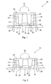
- FIG. 1 shows the longitudinal section through a display device 10.
- two bulbs 20, preferably LEDs are supported.
- a coupling element 16 has, for each luminous means 20, a recess 32 for coupling the light emitted by the luminous means 20 into a channel 22 for guiding light in a reflector body 14.
- the reflector body 14 is optically more dense than the content of the channel 22 for guiding light so that light is reflected at the interface between channel 22 and reflector body 14.
- FIG. 1 In the channel 22, a light guide 24 is positioned from a visually less dense material than the reflector body 14.
- a cover 26 is arranged on the side facing away from the printed circuit board 18 of the reflector body 14 and the light guide 24, wherein light guide 24 and cover 26 are integrally formed of identical material.
- the transition between light guide 24 and cover 26 is indicated by a dashed line.
- a display segment 12th At the transition of the light guide 24 in the cover 26 is a display segment 12th
- the coupling element 16 is elastic and extends in the installed state of the circuit board 18 to the reflector body 14.
- elastic lips 34 are formed, the possible spacing variations between the printed circuit board 18 and reflector body 14 in compensate for built-in condition and keeps the display device 10 under tension so that rattling of the various components of the display device 10 is avoided.
- the Coupling element 16, including the resilient lip 34, as well as the reflector body 14 is light-tight, so that overshoot of a light source in an adjacent channel 22 is omitted.
- locking hooks 36 are also formed, which are latched to fix the display device 10 to the circuit board 18.
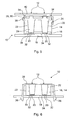
- FIG. 2 illustrated embodiment differs from the in FIG. 1 illustrated in that the coupling element 16 is not formed with a molded resilient lip 34, but the coupling element 16 is formed as a full-surface element. With the exception of the saving 32 for coupling in the light emitted by the luminous means 20, the coupling element 16 is in contact with the printed circuit board 18 and / or with the reflector body 14 essentially over the whole area.
- the lip 34 may be integrally formed on the side of the coupling element 16 facing the reflector body 14.
- FIG. 3 illustrated embodiment shows a coupling element 16 and a reflector body 14, which are designed as a two-component part.
- Coupling element 16 and reflector body 14 are made of the same material.
- the coupling element 16 has a lip 34.
- the thickness compensation effected by the lip 34 can take place by means of an elastically configured reflector body 14.
- FIG. 4 illustrated embodiment shows a display device 10 in flat design.
- Coupling element 16 and reflector body 14 are made in one piece of an elastic material and designed as a full-surface element.
- a cover 26, are integrally formed on the light guide 24, with the coupling element 16, the reflector body 14 and the printed circuit board 18 glued.
- FIG. 5 shows an embodiment with a cover 26 in the form of a mask 30.
- the mask 30 is connected via a flexible connection 38, for example a film hinge, with a coupling element 16.
- the mask 30 is provided with a circumferential, resilient nose 34, which compensates for possible variations in distance between the mounted display device 10 and a display glass 40.
- the nose 34 of the mask 30 acts as a seal.
- the mask 40 may be a separate component or be printed on the cover 26, light guide 24 or scattering film 28.
- Printed circuit board 18, coupling element 16, reflector body 14, optical fiber 24 and mask 30 are glued together. If necessary, the entire display device 10 may also be glued to the display glass 40.
- FIG. 6 a further embodiment of the display device 10 is shown.
- the coupling element 16 and the reflector body 14 are integrally made of the same material, wherein on the reflector body 14 latching hooks 36 are integrally formed for latching with the circuit board 18.
- a channel 22 for guiding light in the reflector body 14 is designed without light guides.
- the cover 26 is a diffused optical film 28.
- coupling element 16, reflector body 14 and light guide 24 can each be present as a separate component (1K part) with different materials.
- coupling element 16 and reflector body 14 can be made as a 2K part with two different or only a single material.
- the combination of coupling element 16, reflector body 14 and light guide 24 may be designed as a 3K part, in which case at least two different materials are required.
Landscapes
- Physics & Mathematics (AREA)
- General Physics & Mathematics (AREA)
- Engineering & Computer Science (AREA)
- Theoretical Computer Science (AREA)
- Illuminated Signs And Luminous Advertising (AREA)
- Devices For Indicating Variable Information By Combining Individual Elements (AREA)
Abstract
Description
Die Erfindung betrifft eine Anzeigeeinrichtung gemäß dem Oberbegriff des Anspruchs 1.The invention relates to a display device according to the preamble of claim 1.
Aus der
Aufgrund des Spalts ist es möglich, dass Streulicht in benachbarte Lichtleiterelemente überkoppelt. Außerdem sitzen die Komponenten der Anzeigeeinrichtung nicht fest, weshalb es während des Betriebs eines Gerätes zu Klappern kommen kann, was den Anschein geringer Qualität hervorruft.Due to the gap, it is possible that stray light coupled into adjacent light guide elements. In addition, the components of the display device are not fixed, which is why it may cause rattling during operation of a device, which gives the appearance of low quality.
In Erkenntnis dieser Gegebenheiten liegt vorliegender Erfindung deshalb die Problemstellung zugrunde, eine Anzeigeeinrichtung bereitzustellen, welche die genannten Nachteile nicht aufweist.In recognition of these circumstances, the present invention is therefore based on the problem to provide a display device which does not have the disadvantages mentioned.
Die Aufgabe wird erfindungsgemäß gelöst durch eine Anzeigeeinrichtung mit wenigstens einem Anzeige-Segment, einem Reflektor-Körper, einem Koppelelement und einer Leiterplatte mit wenigstens einem Leuchtmittel, wobei zwischen dem Anzeige-Segment und dem Leuchtmittel ein Kanal zum Führen von Licht im Reflektor-Körper verläuft, und das Koppelelement zwischen dem Anzeige-Segment und der Leiterplatte angeordnet ist, wobei das Koppelelement elastisch ist.The object is achieved by a display device with at least one display segment, a reflector body, a coupling element and a printed circuit board with at least one light source, wherein a channel for guiding light in the reflector body runs between the display segment and the light source , And the coupling element between the display segment and the circuit board is arranged, wherein the coupling element is elastic.
Mit anderen Worten weist eine Anzeigeeinrichtung neben einem Anzeige-Segment, einen Reflektor-Körper und einer Leiterplatte mit wenigstens einem Leuchtmittel, einen Kanal zum Führen von Licht in dem Reflektor-Körper sowie ein Koppelelement auf. Der Kanal zum Führen von Licht verläuft zwischen dem Leuchtmittel und dem Anzeige-Segment. Das Koppelelement zum Einkoppeln des vom Leuchtmittel ausgestrahlten Lichts in den Kanal des Reflektor-Körpers ist elastisch. Die Elastizität des Koppelelements bewirkt, dass bauteilbedingte Abstandsvariationen zwischen Leiterplatte und Koppelelement bzw. zwischen Koppelelement und Reflektor-Körper der montierten Anzeigeeinrichtung kompensiert werden und ein Spalt zwischen diesen Komponenten verschlossen wird. Somit ist die Passgenauigkeit der Komponenten spielfrei, die Anzeigeeinrichtung ist fest positioniert und beispielsweise beim Schleudern einer Waschmaschine ohne unterbleibt ein Klappergeräusch. Darüber hinaus schirmt das elastische Koppelelement benachbarte Lichtleiter ab, verhindert das Auftreten von Streulicht und ermöglicht das eindeutige Ablesen der angezeigten Information, da ein störendes Nebenleuchten unterbunden ist. Ein hochwertiges Erscheinungsbild der Anzeigeeinrichtung liegt vor.In other words, a display device in addition to a display segment, a reflector body and a printed circuit board with at least one light source, a channel for guiding light in the reflector body and a coupling element. The channel for guiding light passes between the illuminant and the display segment. The coupling element for coupling the light emitted by the light source into the channel of the reflector body is elastic. The elasticity of the coupling element causes component-related distance variations between the printed circuit board and the coupling element or between the coupling element and the reflector body of the mounted display device are compensated and a gap between these components is closed. Thus, the accuracy of fit of the components is free of play, the display device is firmly positioned and, for example, when skidding a washing machine without a rattling noise. In addition, the elastic coupling element shields adjacent optical fibers, prevents the occurrence of scattered light and allows the clear reading of the displayed information, as a disturbing secondary illumination is prevented. A high-quality appearance of the display device is available.
In einer vorteilhaften Weiterbildung ist das Koppelelement mit einer Lippe oder als vollflächiges Element ausgeführt.In an advantageous development, the coupling element is designed with a lip or as a full-surface element.
An das Koppelelement ist eine nachgiebige Lippe angeformt. Zusätzlich oder alternativ dazu ist das Koppelelement als vollflächiges Element aus einem nachgiebig flexiblen Werkstoff gefertigt. Besonders vorteilhaft an einem solchen Koppelelement ist, dass aufgrund dessen Elastizität die Gefahr einer Beschädigung des Leuchtmittels während der Montage der Anzeigeeinrichtung reduziert ist. Als elastischer Werkstoff kommen Schäume und gummiartige Werkstoffe, wie thermoplastische Elastomere, Ethylen-Propylen-Dien-Kautschuke oder Silikone in Frage.At the coupling element a resilient lip is formed. Additionally or alternatively, the coupling element is made as a full-surface element of a resiliently flexible material. It is particularly advantageous on such a coupling element that due to its elasticity, the risk of damage to the lighting means is reduced during assembly of the display device. Suitable elastic materials are foams and rubber-like materials, such as thermoplastic elastomers, ethylene-propylene-diene rubbers or silicones.
In einer bevorzugten Alternative sind das Koppelelement und der Reflektor-Körper lichtdicht. Der Vorteil einer lichtdichten Ausgestaltung ist, dass ein Überleuchten in einen benachbarten Kanal zum Führen von Licht oder in ein benachbartes Anzeigesegment unmöglich ist, da diese gegen unerwünschten Lichteinfall abgeschottet sind.In a preferred alternative, the coupling element and the reflector body are light-tight. The advantage of a light-tight configuration is that it is impossible to overshoot in an adjacent channel for guiding light or in an adjacent display segment, since these are shielded against unwanted light incidence.
In einer weiteren Ausführungsform ist in dem Kanal zum Führen von Licht ein Lichtleiter angeordnet. Ein besonders vorteilhaftes Material für den Lichtleiter ist Polycarbonat (PC) oder Polymethylmethacrylat (PMMA).In a further embodiment, a light guide is arranged in the channel for guiding light. A particularly advantageous material for the light guide is polycarbonate (PC) or polymethyl methacrylate (PMMA).
Vorteilhafterweise sind das Koppelelement und der Reflektor-Körper Komponenten eines Zwei-Komponenten-Teils. Da das Koppelelement und der Reflektor-Körper in einem Zwei-Komponenten-Teil (2K-Teil) zusammengefasst sind, wird ein Zusammenbau der Anzeigeeinrichtung einfacher, da anstelle zweier einkomponentiger Bauteile (1K-Teile) nur ein beide Komponenten aufweisendes 2K-Teil zu verbauen ist. Das Zwei-Komponenten-Teil lässt sich besonders kostengünstig mittels Spritzgießen herstellen. Durch Spritzgießen lassen sich verschiedene Werkstoffe für Koppelelement und Reflektor-Körper in einem Bauteil verbinden. Im Bedarfsfall ist in den im 2K-Teil befindlichen Kanal zum Führen von Licht ein Lichtleiter einsetzbar.Advantageously, the coupling element and the reflector body are components of a two-component part. Since the coupling element and the reflector body are combined in a two-component part (2K part), an assembly of the display device is easier because instead of two one-component components (1K parts) to install only a two-component 2K-part is. The two-component part can be produced particularly cost-effectively by means of injection molding. By injection molding, different materials for coupling element and reflector body can be combined in one component. If necessary, a light guide can be used in the channel located in the 2K part for guiding light.
Zweckmäßigerweise sind das Koppelelement, der Reflektor-Körper und der Lichtleiter Komponenten eines Drei-Komponenten-Teils. Da das Koppelelement, der Reflektor-Körper und der Lichtleiter in einem Drei-Komponenten-Teil (3K-Teil) zusammengefasst sind, wird ein Zusammenbau der Anzeigeeinrichtung einfacher, da anstelle dreier einkomponentiger Bauteile (1K-Teile) nur ein drei Komponenten aufweisendes 3K-Teil zu verbauen ist. Das Drei-Komponenten-Teil lässt sich besonders kostengünstig mittels Spritzgießen herstellen. Durch Spritzgießen lassen sich verschiedene Werkstoffe für Koppelelement, Reflektor-Körper und Lichtleiter in einem Bauteil verbinden.Conveniently, the coupling element, the reflector body and the light guide components of a three-component part. Since the coupling element, the reflector body and the light guide in a three-component part (3K part) are summarized, an assembly of the display device is easier, since instead of three one-component components (1K parts) is to install only a three-component 3K-part having. The three-component part can be produced particularly cost-effectively by means of injection molding. By injection molding, different materials for coupling element, reflector body and light guide can be combined in one component.
In einer weiteren Ausgestaltung sind das Koppelelement und der Reflektor-Körper aus dem gleichen Werkstoff gefertigt. Besonders vorteilhaft ist, wenn das Koppelelement und der Reflektor-Körper aus dem gleichen, bevorzugt einem elastischem Werkstoff gefertigt ist, da sich hierdurch der Herstellungsaufwand weiter vereinfacht. Sind Koppelelement und Reflektor-Körper aus dem gleichen elastischen Material, ist die Anzeigeeinrichtung in Flachbauweise herstellbar.In a further embodiment, the coupling element and the reflector body are made of the same material. It is particularly advantageous if the coupling element and the reflector body is made of the same, preferably an elastic material, since this further simplifies the production cost. Are coupling element and reflector body made of the same elastic material, the display device can be produced in flat design.
In einer besonders vorteilhaften Weiterbildung weist die Anzeigeeinrichtung eine Abdeckung auf. Eine Abdeckung bietet die Möglichkeit die Komponenten einer Anzeigeeinrichtung zu schützen und ist als Träger für Variationen des Designs zu nutzbar.In a particularly advantageous development, the display device has a cover. A cover offers the possibility of protecting the components of a display device and can be used as a support for variations of the design.
Vorteilhafterweise sind die Abdeckung und der Lichtleiter einteilig ausgebildet. Durch die einteilige Ausgestaltung von Abdeckung und Lichtleiter, dieser geht in die Abdeckung über, ist die Anzeigeeinrichtung kompakter und die Herstellung dieser einteiligen Komponente sowie deren Montage ist vereinfacht.Advantageously, the cover and the light guide are integrally formed. Due to the one-piece design of the cover and light guide, this goes into the cover, the display device is more compact and the production of this one-piece component and their assembly is simplified.
Zweckmäßigerweise ist der Lichtleiter optisch diffus. Hierdurch ist eine gleichmäßige Beleuchtung des Anzeige-Segments der Anzeigeeinrichtung gewährleistet.Conveniently, the optical fiber is optically diffuse. This ensures a uniform illumination of the display segment of the display device.
In einer weiteren Ausgestaltung ist die Abdeckung eine optische Streufolie. Im Fall einer Anzeigeeinrichtung ohne Lichtleiter bewirkt die optische Streufolie eine gleichmäßige Ausleuchtung.In a further embodiment, the cover is an optical scattering film. In the case of a display device without a light guide, the scattering optical film causes uniform illumination.
Vorteilhafterweise ist die Abdeckung eine Maske. Durch die Maske lässt sich der Kontrast eines Anzeige-Segments verbessern und verschiedene Umrisse oder Symbole darstellen.Advantageously, the cover is a mask. The mask improves the contrast of a display segment and displays different outlines or symbols.
In einer weiteren Ausführungsform ist die Maske aus dem gleichen Werkstoff gefertigt, wie das Koppelelement und der Reflektor-Körper.In a further embodiment, the mask is made of the same material as the coupling element and the reflector body.
Ist die Maske aus dem gleichen Werkstoff wie das Koppelelement gefertigt, kann die Maske die Funktion einer Dichtung übernehmen sowie als Toleranzausgleich wirken. Ist eine Anzeigeeinrichtung unter einem Anzeigefenster, beispielsweise einem Display-Fenster angeordnet, kann die Maske den Raum zwischen der Anzeigeeinrichtung und dem Anzeigefenster abdichten und Abstandsschwankungen ausgleichen, analog einem Koppelelement zwischen einer Leiterplatte und einem Reflektor-Körper.If the mask is made of the same material as the coupling element, the mask can assume the function of a seal and act as a tolerance compensation. If a display device is arranged under a display window, for example a display window, the mask can seal the space between the display device and the display window and compensate for variations in the distance, analogously to a coupling element between a printed circuit board and a reflector body.
In einer bevorzugten Alternative sind das Koppelelement, der Reflektor-Körper und die Maske einteilig ausgebildet. Durch die einteilige Ausbildung von Koppelelement, Reflektor-Körper und Maske lässt sich die Montage vereinfachen. Ist die Maske beispielsweise am Reflektor-Körper über einen flexiblen Steg oder ein Filmscharnier mit der Maske verbunden, lässt sich diese auf der dem Reflektor-Körper abgewandten Seite eines Lichtleiters positionieren.In a preferred alternative, the coupling element, the reflector body and the mask are integrally formed. Due to the one-piece design of coupling element, reflector body and mask, the assembly can be simplified. If the mask is connected, for example, to the reflector body via a flexible web or a film hinge with the mask, it can be positioned on the side of a light guide facing away from the reflector body.
In einer vorteilhaften Weiterbildung sind die Komponenten der Anzeigeeinrichtung miteinander verrastet oder verklebt. Die Montage durch Verrastung bietet eine einfache Möglichkeit die Anzeigeeinrichtung zu fixieren und diese im Bedarfsfall wieder demontieren zu können. Eine dauerhafte Fixierung lässt sich durch Verkleben der Komponenten der Anzeigeeinrichtung erzielen, wobei ein reduzierter Platzbedarf besteht.In an advantageous development, the components of the display device are locked or glued together. The installation by locking provides an easy way to fix the display device and this can be dismantled if necessary. A permanent fixation can be achieved by gluing the components of the display device, with a reduced space requirement.
Mehrere Ausführungsbeispiele werden anhand der Zeichnung und der nachstehenden Beschreibung näher erläutert. Es zeigt
- Fig. 1
- einen Längsschnitt durch ein erstes Ausführungsbeispiel,
- Fig. 2
- einen Längsschnitt durch ein zweites Ausführungsbeispiel,
- Fig. 3
- einen Längsschnitt durch ein drittes Ausführungsbeispiel,
- Fig. 4
- einen Längsschnitt durch ein viertes Ausführungsbeispiel,
- Fig. 5
- einen Längsschnitt durch ein fünftes Ausführungsbeispiel und
- Fig. 6
- einen Längsschnitt durch ein sechstes Ausführungsbeispiel.
- Fig. 1
- a longitudinal section through a first embodiment,
- Fig. 2
- a longitudinal section through a second embodiment,
- Fig. 3
- a longitudinal section through a third embodiment,
- Fig. 4
- a longitudinal section through a fourth embodiment,
- Fig. 5
- a longitudinal section through a fifth embodiment and
- Fig. 6
- a longitudinal section through a sixth embodiment.
Das Koppelelement 16 ist elastisch und erstreckt sich im eingebauten Zustand von der Leiterplatte 18 bis zum Reflektor-Körper 14. Auf der der Leiterplatte 18 zugewandten Seite des Koppelelements 16 sind elastische Lippen 34 ausgeformt, die mögliche Abstandsschwankungen zwischen Leiterplatte 18 und Reflektor-Körper 14 im eingebauten Zustand ausgleichen und die Anzeigeneinrichtung 10 so unter Spannung hält, dass ein Klappern der verschiedenen Komponenten der Anzeigeeinrichtung 10 vermieden wird. Das Koppelelement 16, einschließlich der nachgiebigen Lippe 34, ist ebenso wie der Reflektor-Körper 14 lichtdicht, so dass ein Überstrahlen eines Leuchtmittels in einen benachbarten Kanal 22 unterbleibt.The
An der Abdeckung 26 sind außerdem Rasthaken 36 angeformt, die zur Fixierung der Anzeigeneinrichtung 10 mit der Leiterplatte 18 verrastet sind.On the
Das in
In einer alternativen Ausführung kann die Lippe 34 an der dem Reflektor-Körper 14 zugewandten Seite des Koppelelements 16 angeformt sein.In an alternative embodiment, the
Das in
Das in
Die Maske 40 kann ein separates Bauteil sein oder auf die Abdeckung 26, Lichtleiter 24 oder Streufolie 28 aufgedruckt sein.The
Leiterplatte 18, Koppelelement 16, Reflektor-Körper 14, Lichtleiter 24 und Maske 30 sind miteinander verklebt. Im Bedarfsfall kann die gesamte Anzeigeeinrichtung 10 ebenfalls mit dem Display-Glas 40 verklebt sein.Printed
In
Alle Ausführungsbeispiele können auf verschiedene Art und Weise realisiert sein. So können Koppelelement 16, Reflektor-Körper 14 und Lichtleiter 24 jeweils als separates Bauteil (1K-Teil) mit unterschiedlichen Werkstoffen vorliegen. Alternativ dazu können Koppelelement 16 und Reflektor-Körper 14 als 2K-Teil mit zwei verschiedenen oder nur einem einzigen Werkstoff hergestellt sein. Die Kombination aus Koppelelement 16, Reflektor-Körper 14 und Lichtleiter 24 kann als 3K-Teil ausgeführt sein, wobei hier wenigstens zwei unterschiedliche Werkstoffe erforderlich sind.All embodiments can be realized in various ways. Thus,
Claims (15)
mit wenigstens einem Anzeige-Segment (12), einem Reflektor-Körper (14), einem Koppelelement (16) und einer Leiterplatte (18) mit wenigstens einem Leuchtmittel (20), wobei zwischen dem Anzeige-Segment (12) und dem Leuchtmittel (20) ein Kanal (22) zum Führen von Licht in dem Reflektor-Körper (14) verläuft, und das Koppelelement (16) zwischen dem Anzeige-Segment (12) und der Leiterplatte (18) angeordnet ist,
dadurch gekennzeichnet,
dass das Koppelelement (16) elastisch ist.Display device (10)
with at least one display segment (12), a reflector body (14), a coupling element (16) and a printed circuit board (18) with at least one light source (20), wherein between the display segment (12) and the light source ( 20) a channel (22) for guiding light in the reflector body (14) extends, and the coupling element (16) between the display segment (12) and the circuit board (18) is arranged,
characterized,
that the coupling element (16) is elastic.
dadurch gekennzeichnet,
dass das Koppelelement (16) mit einer Lippe (34) oder als vollflächiges Element ausgeführt ist.Display device (10) according to claim 1,
characterized,
that the coupling element (16) is designed with a lip (34) or as a full-surface element.
dadurch gekennzeichnet,
dass das Koppelelement (16) und der Reflektor-Körper (14) lichtdicht sind.Display device (10) according to claim 1 or 2,
characterized,
that the coupling element (16) and the reflector body (14) are light-tight.
dadurch gekennzeichnet,
dass in dem Kanal (22) zum Führen von Licht ein Lichtleiter (24) angeordnet ist.Display device (10) according to one of the preceding claims,
characterized,
in that a light guide (24) is arranged in the channel (22) for guiding light.
dadurch gekennzeichnet,
dass das Koppelelement (16) und der Reflektor-Körper (14) Komponenten eines Zwei-Komponenten-Teils sind.Display device (10) according to one of the preceding claims,
characterized,
in that the coupling element (16) and the reflector body (14) are components of a two-component part.
dadurch gekennzeichnet,
dass das Koppelelement (16), der Reflektor-Körper (14) und der Lichtleiter (24) Komponenten eines Drei-Komponenten-Teils sind.Display device (10) according to one of claims 1 to 4,
characterized,
in that the coupling element (16), the reflector body (14) and the light guide (24) are components of a three-component part.
dadurch gekennzeichnet,
dass das Koppelelement (16) und der Reflektor-Körper (14) aus dem gleichen Werkstoff gefertigt sind.Display device (10) according to claim 5 or 6,
characterized,
that the coupling element (16) and the reflector body (14) are made of the same material.
dadurch gekennzeichnet,
dass die Anzeigeeinrichtung (10) eine Abdeckung (26) aufweist.Display device (10) according to one of the preceding claims,
characterized,
that the display device (10) comprises a cover (26).
dadurch gekennzeichnet,
dass die Abdeckung (26) und der Lichtleiter (24) einteilig ausgebildet sind.Display device (10) according to claim 8,
characterized,
that the cover (26) and the light guide (24) are integrally formed.
dadurch gekennzeichnet,
dass der Lichtleiter (24) optisch diffus ist.Display device (10) according to one of claims 4 to 9,
characterized,
that the light guide (24) is optically diffuse.
dadurch gekennzeichnet,
dass die Abdeckung (26) eine optische Streufolie (28) ist.Display device (10) according to claim 8,
characterized,
that the cover (26) is an optical scattering film (28).
dadurch gekennzeichnet,
dass die Abdeckung (26) eine Maske (30) ist.Display device (10) according to claim 8,
characterized,
that the cover (26) is a mask (30).
dadurch gekennzeichnet,
dass die Maske (30) aus dem gleichen Werkstoff gefertigt ist, wie das Koppelelement (16) und der Reflektor-Körper (14).Display device (10) according to claim 12,
characterized,
that the mask (30) is made of the same material as the coupling element (16) and the reflector body (14).
dadurch gekennzeichnet,
dass das Koppelelement (16), der Reflektor-Körper (14) und die Maske (30) einteilig ausgebildet sind.Display device (10) according to claim 13,
characterized,
that the coupling element (16), the reflector body (14) and the mask (30) are integrally formed.
dadurch gekennzeichnet,
dass die Komponenten der Anzeigeeinrichtung (10) miteinander verrastet oder verklebt sind.Display device (10) according to one of the preceding claims,
characterized,
that the components of the display device (10) are locked or glued together.
Priority Applications (1)
| Application Number | Priority Date | Filing Date | Title |
|---|---|---|---|
| PL11004949T PL2400478T3 (en) | 2010-06-26 | 2011-06-17 | Display device |
Applications Claiming Priority (1)
| Application Number | Priority Date | Filing Date | Title |
|---|---|---|---|
| DE201010025247 DE102010025247A1 (en) | 2010-06-26 | 2010-06-26 | display |
Publications (3)
| Publication Number | Publication Date |
|---|---|
| EP2400478A2 true EP2400478A2 (en) | 2011-12-28 |
| EP2400478A3 EP2400478A3 (en) | 2012-05-09 |
| EP2400478B1 EP2400478B1 (en) | 2016-11-02 |
Family
ID=44675912
Family Applications (1)
| Application Number | Title | Priority Date | Filing Date |
|---|---|---|---|
| EP11004949.1A Not-in-force EP2400478B1 (en) | 2010-06-26 | 2011-06-17 | Display device |
Country Status (3)
| Country | Link |
|---|---|
| EP (1) | EP2400478B1 (en) |
| DE (1) | DE102010025247A1 (en) |
| PL (1) | PL2400478T3 (en) |
Cited By (3)
| Publication number | Priority date | Publication date | Assignee | Title |
|---|---|---|---|---|
| WO2014086408A1 (en) * | 2012-12-05 | 2014-06-12 | Thomas Verkehrstechnik Gmbh | Display unit for modular message board |
| WO2015011179A1 (en) * | 2013-07-23 | 2015-01-29 | Zumtobel Lighting Gmbh | Led illumination module |
| FR3071904A1 (en) * | 2017-10-02 | 2019-04-05 | Psa Automobiles Sa | LIGHTING DEVICE PROTECTED AGAINST LIGHT LEAKS |
Families Citing this family (1)
| Publication number | Priority date | Publication date | Assignee | Title |
|---|---|---|---|---|
| DE202012011860U1 (en) | 2012-12-12 | 2014-03-13 | Oechsler Ag | Equipment article |
Citations (1)
| Publication number | Priority date | Publication date | Assignee | Title |
|---|---|---|---|---|
| WO2002074041A2 (en) | 2001-03-16 | 2002-09-26 | Diehl Ako Stiftung & Co. Kg | Display device |
Family Cites Families (4)
| Publication number | Priority date | Publication date | Assignee | Title |
|---|---|---|---|---|
| JP4082768B2 (en) * | 1997-12-04 | 2008-04-30 | 株式会社キーエンス | display |
| DE10230023C5 (en) * | 2002-07-04 | 2010-12-23 | Diehl Ako Stiftung & Co. Kg | Optical signal transmitter, in particular for the control panel of a large household appliance |
| DE10333316A1 (en) * | 2003-07-22 | 2005-02-10 | BSH Bosch und Siemens Hausgeräte GmbH | Optical fiber component for optical multi-segment displays |
| DE102008055865A1 (en) * | 2008-11-05 | 2010-05-12 | Lisa Dräxlmaier GmbH | Sensing device for operating electrical load in vehicle, particularly for integration in body trim, has fixed elastically deformed actuating surface, and flat elastically deformed light guide for illuminating symbolism |
-
2010
- 2010-06-26 DE DE201010025247 patent/DE102010025247A1/en not_active Ceased
-
2011
- 2011-06-17 EP EP11004949.1A patent/EP2400478B1/en not_active Not-in-force
- 2011-06-17 PL PL11004949T patent/PL2400478T3/en unknown
Patent Citations (1)
| Publication number | Priority date | Publication date | Assignee | Title |
|---|---|---|---|---|
| WO2002074041A2 (en) | 2001-03-16 | 2002-09-26 | Diehl Ako Stiftung & Co. Kg | Display device |
Cited By (3)
| Publication number | Priority date | Publication date | Assignee | Title |
|---|---|---|---|---|
| WO2014086408A1 (en) * | 2012-12-05 | 2014-06-12 | Thomas Verkehrstechnik Gmbh | Display unit for modular message board |
| WO2015011179A1 (en) * | 2013-07-23 | 2015-01-29 | Zumtobel Lighting Gmbh | Led illumination module |
| FR3071904A1 (en) * | 2017-10-02 | 2019-04-05 | Psa Automobiles Sa | LIGHTING DEVICE PROTECTED AGAINST LIGHT LEAKS |
Also Published As
| Publication number | Publication date |
|---|---|
| EP2400478A3 (en) | 2012-05-09 |
| PL2400478T3 (en) | 2017-04-28 |
| EP2400478B1 (en) | 2016-11-02 |
| DE102010025247A1 (en) | 2011-12-29 |
Similar Documents
| Publication | Publication Date | Title |
|---|---|---|
| EP3194210B1 (en) | Lighting device with lightguide assembly which can be locked therein | |
| DE102006002322B4 (en) | Lighting unit for vehicles with a holding module for the latching connection of light-conducting elements, a carrier module and a side wall | |
| EP2400478B1 (en) | Display device | |
| EP2407852A1 (en) | Support for an operating device | |
| EP2565081A2 (en) | Circular lighting device for a vehicle component | |
| DE102010027685B4 (en) | Positioning structure of an indicator lamp assembly in an outside mirror with an indicator lamp | |
| DE102006007134A1 (en) | Lighting device for use in motor vehicles, comprises housing, housing locking, translucent cover plate, and light sources, light-guiding element is partially connected with light diffuser | |
| WO2018149741A1 (en) | Lighting device for an interior trim part | |
| DE102013012227A1 (en) | Lamp i.e. headlight, for mounting on body part i.e. bumper, of motor vehicle, has housing, and guide that is arranged on body part of counterpart for alignment of lamp on body part that is predefined, where guide is arranged at end lens | |
| DE102014104756A1 (en) | Lighting device for vehicles | |
| DE102012007366A1 (en) | Light arrangement for vehicle light, has light guide element and light sources, where translucent casing is arranged between light source and light guide element, where light is injected into light guide element | |
| DE112019003389T5 (en) | HEAD-UP DISPLAY | |
| DE102013011605B4 (en) | Roller blind arrangement with integrated lighting | |
| EP1762427B1 (en) | Lighting unit for receptacles of electric cigarette lighters | |
| DE102012101574B4 (en) | Mounting arrangement of a display device and method of mounting the display device | |
| WO2017102401A1 (en) | Lighting device for a vehicle | |
| DE202018100278U1 (en) | Control / display module for a dishwasher | |
| DE102019212088A1 (en) | Glass roof arrangement for a motor vehicle and lighting device for such a glass roof arrangement | |
| DE102020100103A1 (en) | Outside mirror for a vehicle, holding system for use with a functional component of a vehicle | |
| DE3326972C2 (en) | ||
| EP1767402B1 (en) | Indicator device | |
| DE102022108689A1 (en) | Vehicle window with a lighting device | |
| DE102014105992A1 (en) | Cover for a motor vehicle roof | |
| DE19740424A1 (en) | Dashboard display device for automobile using liquid crystal cell | |
| DE102014201523B4 (en) | Operating unit, in particular for a vehicle component |
Legal Events
| Date | Code | Title | Description |
|---|---|---|---|
| AK | Designated contracting states |
Kind code of ref document: A2 Designated state(s): AL AT BE BG CH CY CZ DE DK EE ES FI FR GB GR HR HU IE IS IT LI LT LU LV MC MK MT NL NO PL PT RO RS SE SI SK SM TR |
|
| AX | Request for extension of the european patent |
Extension state: BA ME |
|
| PUAI | Public reference made under article 153(3) epc to a published international application that has entered the european phase |
Free format text: ORIGINAL CODE: 0009012 |
|
| PUAL | Search report despatched |
Free format text: ORIGINAL CODE: 0009013 |
|
| AK | Designated contracting states |
Kind code of ref document: A3 Designated state(s): AL AT BE BG CH CY CZ DE DK EE ES FI FR GB GR HR HU IE IS IT LI LT LU LV MC MK MT NL NO PL PT RO RS SE SI SK SM TR |
|
| AX | Request for extension of the european patent |
Extension state: BA ME |
|
| RIC1 | Information provided on ipc code assigned before grant |
Ipc: G09F 9/33 20060101AFI20120330BHEP Ipc: G09F 9/302 20060101ALI20120330BHEP |
|
| 17P | Request for examination filed |
Effective date: 20120803 |
|
| GRAP | Despatch of communication of intention to grant a patent |
Free format text: ORIGINAL CODE: EPIDOSNIGR1 |
|
| INTG | Intention to grant announced |
Effective date: 20160519 |
|
| GRAS | Grant fee paid |
Free format text: ORIGINAL CODE: EPIDOSNIGR3 |
|
| GRAA | (expected) grant |
Free format text: ORIGINAL CODE: 0009210 |
|
| AK | Designated contracting states |
Kind code of ref document: B1 Designated state(s): AL AT BE BG CH CY CZ DE DK EE ES FI FR GB GR HR HU IE IS IT LI LT LU LV MC MK MT NL NO PL PT RO RS SE SI SK SM TR |
|
| REG | Reference to a national code |
Ref country code: GB Ref legal event code: FG4D Free format text: NOT ENGLISH |
|
| REG | Reference to a national code |
Ref country code: AT Ref legal event code: REF Ref document number: 842536 Country of ref document: AT Kind code of ref document: T Effective date: 20161115 Ref country code: CH Ref legal event code: EP |
|
| REG | Reference to a national code |
Ref country code: IE Ref legal event code: FG4D Free format text: LANGUAGE OF EP DOCUMENT: GERMAN |
|
| REG | Reference to a national code |
Ref country code: DE Ref legal event code: R096 Ref document number: 502011011018 Country of ref document: DE |
|
| PG25 | Lapsed in a contracting state [announced via postgrant information from national office to epo] |
Ref country code: LV Free format text: LAPSE BECAUSE OF FAILURE TO SUBMIT A TRANSLATION OF THE DESCRIPTION OR TO PAY THE FEE WITHIN THE PRESCRIBED TIME-LIMIT Effective date: 20161102 |
|
| REG | Reference to a national code |
Ref country code: NL Ref legal event code: MP Effective date: 20161102 |
|
| REG | Reference to a national code |
Ref country code: LT Ref legal event code: MG4D |
|
| PG25 | Lapsed in a contracting state [announced via postgrant information from national office to epo] |
Ref country code: SE Free format text: LAPSE BECAUSE OF FAILURE TO SUBMIT A TRANSLATION OF THE DESCRIPTION OR TO PAY THE FEE WITHIN THE PRESCRIBED TIME-LIMIT Effective date: 20161102 Ref country code: NL Free format text: LAPSE BECAUSE OF FAILURE TO SUBMIT A TRANSLATION OF THE DESCRIPTION OR TO PAY THE FEE WITHIN THE PRESCRIBED TIME-LIMIT Effective date: 20161102 Ref country code: LT Free format text: LAPSE BECAUSE OF FAILURE TO SUBMIT A TRANSLATION OF THE DESCRIPTION OR TO PAY THE FEE WITHIN THE PRESCRIBED TIME-LIMIT Effective date: 20161102 Ref country code: GR Free format text: LAPSE BECAUSE OF FAILURE TO SUBMIT A TRANSLATION OF THE DESCRIPTION OR TO PAY THE FEE WITHIN THE PRESCRIBED TIME-LIMIT Effective date: 20170203 Ref country code: NO Free format text: LAPSE BECAUSE OF FAILURE TO SUBMIT A TRANSLATION OF THE DESCRIPTION OR TO PAY THE FEE WITHIN THE PRESCRIBED TIME-LIMIT Effective date: 20170202 |
|
| PG25 | Lapsed in a contracting state [announced via postgrant information from national office to epo] |
Ref country code: HR Free format text: LAPSE BECAUSE OF FAILURE TO SUBMIT A TRANSLATION OF THE DESCRIPTION OR TO PAY THE FEE WITHIN THE PRESCRIBED TIME-LIMIT Effective date: 20161102 Ref country code: IS Free format text: LAPSE BECAUSE OF FAILURE TO SUBMIT A TRANSLATION OF THE DESCRIPTION OR TO PAY THE FEE WITHIN THE PRESCRIBED TIME-LIMIT Effective date: 20170302 Ref country code: FI Free format text: LAPSE BECAUSE OF FAILURE TO SUBMIT A TRANSLATION OF THE DESCRIPTION OR TO PAY THE FEE WITHIN THE PRESCRIBED TIME-LIMIT Effective date: 20161102 Ref country code: RS Free format text: LAPSE BECAUSE OF FAILURE TO SUBMIT A TRANSLATION OF THE DESCRIPTION OR TO PAY THE FEE WITHIN THE PRESCRIBED TIME-LIMIT Effective date: 20161102 Ref country code: PT Free format text: LAPSE BECAUSE OF FAILURE TO SUBMIT A TRANSLATION OF THE DESCRIPTION OR TO PAY THE FEE WITHIN THE PRESCRIBED TIME-LIMIT Effective date: 20170302 Ref country code: ES Free format text: LAPSE BECAUSE OF FAILURE TO SUBMIT A TRANSLATION OF THE DESCRIPTION OR TO PAY THE FEE WITHIN THE PRESCRIBED TIME-LIMIT Effective date: 20161102 |
|
| PG25 | Lapsed in a contracting state [announced via postgrant information from national office to epo] |
Ref country code: SK Free format text: LAPSE BECAUSE OF FAILURE TO SUBMIT A TRANSLATION OF THE DESCRIPTION OR TO PAY THE FEE WITHIN THE PRESCRIBED TIME-LIMIT Effective date: 20161102 Ref country code: EE Free format text: LAPSE BECAUSE OF FAILURE TO SUBMIT A TRANSLATION OF THE DESCRIPTION OR TO PAY THE FEE WITHIN THE PRESCRIBED TIME-LIMIT Effective date: 20161102 Ref country code: RO Free format text: LAPSE BECAUSE OF FAILURE TO SUBMIT A TRANSLATION OF THE DESCRIPTION OR TO PAY THE FEE WITHIN THE PRESCRIBED TIME-LIMIT Effective date: 20161102 Ref country code: CZ Free format text: LAPSE BECAUSE OF FAILURE TO SUBMIT A TRANSLATION OF THE DESCRIPTION OR TO PAY THE FEE WITHIN THE PRESCRIBED TIME-LIMIT Effective date: 20161102 Ref country code: DK Free format text: LAPSE BECAUSE OF FAILURE TO SUBMIT A TRANSLATION OF THE DESCRIPTION OR TO PAY THE FEE WITHIN THE PRESCRIBED TIME-LIMIT Effective date: 20161102 |
|
| REG | Reference to a national code |
Ref country code: DE Ref legal event code: R097 Ref document number: 502011011018 Country of ref document: DE |
|
| PG25 | Lapsed in a contracting state [announced via postgrant information from national office to epo] |
Ref country code: IT Free format text: LAPSE BECAUSE OF FAILURE TO SUBMIT A TRANSLATION OF THE DESCRIPTION OR TO PAY THE FEE WITHIN THE PRESCRIBED TIME-LIMIT Effective date: 20161102 Ref country code: BG Free format text: LAPSE BECAUSE OF FAILURE TO SUBMIT A TRANSLATION OF THE DESCRIPTION OR TO PAY THE FEE WITHIN THE PRESCRIBED TIME-LIMIT Effective date: 20170202 Ref country code: SM Free format text: LAPSE BECAUSE OF FAILURE TO SUBMIT A TRANSLATION OF THE DESCRIPTION OR TO PAY THE FEE WITHIN THE PRESCRIBED TIME-LIMIT Effective date: 20161102 |
|
| PGFP | Annual fee paid to national office [announced via postgrant information from national office to epo] |
Ref country code: PL Payment date: 20170613 Year of fee payment: 7 |
|
| PLBE | No opposition filed within time limit |
Free format text: ORIGINAL CODE: 0009261 |
|
| STAA | Information on the status of an ep patent application or granted ep patent |
Free format text: STATUS: NO OPPOSITION FILED WITHIN TIME LIMIT |
|
| PGFP | Annual fee paid to national office [announced via postgrant information from national office to epo] |
Ref country code: TR Payment date: 20170531 Year of fee payment: 7 |
|
| 26N | No opposition filed |
Effective date: 20170803 |
|
| PG25 | Lapsed in a contracting state [announced via postgrant information from national office to epo] |
Ref country code: SI Free format text: LAPSE BECAUSE OF FAILURE TO SUBMIT A TRANSLATION OF THE DESCRIPTION OR TO PAY THE FEE WITHIN THE PRESCRIBED TIME-LIMIT Effective date: 20161102 |
|
| PG25 | Lapsed in a contracting state [announced via postgrant information from national office to epo] |
Ref country code: MC Free format text: LAPSE BECAUSE OF FAILURE TO SUBMIT A TRANSLATION OF THE DESCRIPTION OR TO PAY THE FEE WITHIN THE PRESCRIBED TIME-LIMIT Effective date: 20161102 |
|
| REG | Reference to a national code |
Ref country code: CH Ref legal event code: PL |
|
| GBPC | Gb: european patent ceased through non-payment of renewal fee |
Effective date: 20170617 |
|
| REG | Reference to a national code |
Ref country code: IE Ref legal event code: MM4A |
|
| REG | Reference to a national code |
Ref country code: FR Ref legal event code: ST Effective date: 20180228 |
|
| PG25 | Lapsed in a contracting state [announced via postgrant information from national office to epo] |
Ref country code: CH Free format text: LAPSE BECAUSE OF NON-PAYMENT OF DUE FEES Effective date: 20170630 Ref country code: LI Free format text: LAPSE BECAUSE OF NON-PAYMENT OF DUE FEES Effective date: 20170630 Ref country code: LU Free format text: LAPSE BECAUSE OF NON-PAYMENT OF DUE FEES Effective date: 20170617 Ref country code: IE Free format text: LAPSE BECAUSE OF NON-PAYMENT OF DUE FEES Effective date: 20170617 Ref country code: GB Free format text: LAPSE BECAUSE OF NON-PAYMENT OF DUE FEES Effective date: 20170617 |
|
| PG25 | Lapsed in a contracting state [announced via postgrant information from national office to epo] |
Ref country code: FR Free format text: LAPSE BECAUSE OF NON-PAYMENT OF DUE FEES Effective date: 20170630 |
|
| REG | Reference to a national code |
Ref country code: BE Ref legal event code: MM Effective date: 20170630 |
|
| REG | Reference to a national code |
Ref country code: AT Ref legal event code: MM01 Ref document number: 842536 Country of ref document: AT Kind code of ref document: T Effective date: 20170617 |
|
| PG25 | Lapsed in a contracting state [announced via postgrant information from national office to epo] |
Ref country code: BE Free format text: LAPSE BECAUSE OF NON-PAYMENT OF DUE FEES Effective date: 20170630 |
|
| PG25 | Lapsed in a contracting state [announced via postgrant information from national office to epo] |
Ref country code: MT Free format text: LAPSE BECAUSE OF FAILURE TO SUBMIT A TRANSLATION OF THE DESCRIPTION OR TO PAY THE FEE WITHIN THE PRESCRIBED TIME-LIMIT Effective date: 20161102 |
|
| PGFP | Annual fee paid to national office [announced via postgrant information from national office to epo] |
Ref country code: DE Payment date: 20180821 Year of fee payment: 8 |
|
| PG25 | Lapsed in a contracting state [announced via postgrant information from national office to epo] |
Ref country code: AT Free format text: LAPSE BECAUSE OF NON-PAYMENT OF DUE FEES Effective date: 20170617 |
|
| PG25 | Lapsed in a contracting state [announced via postgrant information from national office to epo] |
Ref country code: HU Free format text: LAPSE BECAUSE OF FAILURE TO SUBMIT A TRANSLATION OF THE DESCRIPTION OR TO PAY THE FEE WITHIN THE PRESCRIBED TIME-LIMIT; INVALID AB INITIO Effective date: 20110617 |
|
| PG25 | Lapsed in a contracting state [announced via postgrant information from national office to epo] |
Ref country code: CY Free format text: LAPSE BECAUSE OF NON-PAYMENT OF DUE FEES Effective date: 20161102 |
|
| PG25 | Lapsed in a contracting state [announced via postgrant information from national office to epo] |
Ref country code: MK Free format text: LAPSE BECAUSE OF FAILURE TO SUBMIT A TRANSLATION OF THE DESCRIPTION OR TO PAY THE FEE WITHIN THE PRESCRIBED TIME-LIMIT Effective date: 20161102 Ref country code: PL Free format text: LAPSE BECAUSE OF NON-PAYMENT OF DUE FEES Effective date: 20180617 |
|
| REG | Reference to a national code |
Ref country code: DE Ref legal event code: R119 Ref document number: 502011011018 Country of ref document: DE |
|
| PG25 | Lapsed in a contracting state [announced via postgrant information from national office to epo] |
Ref country code: DE Free format text: LAPSE BECAUSE OF NON-PAYMENT OF DUE FEES Effective date: 20200101 |
|
| PG25 | Lapsed in a contracting state [announced via postgrant information from national office to epo] |
Ref country code: AL Free format text: LAPSE BECAUSE OF FAILURE TO SUBMIT A TRANSLATION OF THE DESCRIPTION OR TO PAY THE FEE WITHIN THE PRESCRIBED TIME-LIMIT Effective date: 20161102 |
|
| PG25 | Lapsed in a contracting state [announced via postgrant information from national office to epo] |
Ref country code: TR Free format text: LAPSE BECAUSE OF NON-PAYMENT OF DUE FEES Effective date: 20180617 |