EP2400275B1 - Berührungslose füllstandsmessung von flüssigkeiten - Google Patents
Berührungslose füllstandsmessung von flüssigkeiten Download PDFInfo
- Publication number
- EP2400275B1 EP2400275B1 EP11169037.6A EP11169037A EP2400275B1 EP 2400275 B1 EP2400275 B1 EP 2400275B1 EP 11169037 A EP11169037 A EP 11169037A EP 2400275 B1 EP2400275 B1 EP 2400275B1
- Authority
- EP
- European Patent Office
- Prior art keywords
- measurement
- electrodes
- container
- electrode
- measuring
- Prior art date
- Legal status (The legal status is an assumption and is not a legal conclusion. Google has not performed a legal analysis and makes no representation as to the accuracy of the status listed.)
- Active
Links
Images

Classifications
-
- G—PHYSICS
- G01—MEASURING; TESTING
- G01F—MEASURING VOLUME, VOLUME FLOW, MASS FLOW OR LIQUID LEVEL; METERING BY VOLUME
- G01F23/00—Indicating or measuring liquid level or level of fluent solid material, e.g. indicating in terms of volume or indicating by means of an alarm
- G01F23/22—Indicating or measuring liquid level or level of fluent solid material, e.g. indicating in terms of volume or indicating by means of an alarm by measuring physical variables, other than linear dimensions, pressure or weight, dependent on the level to be measured, e.g. by difference of heat transfer of steam or water
- G01F23/26—Indicating or measuring liquid level or level of fluent solid material, e.g. indicating in terms of volume or indicating by means of an alarm by measuring physical variables, other than linear dimensions, pressure or weight, dependent on the level to be measured, e.g. by difference of heat transfer of steam or water by measuring variations of capacity or inductance of capacitors or inductors arising from the presence of liquid or fluent solid material in the electric or electromagnetic fields
- G01F23/263—Indicating or measuring liquid level or level of fluent solid material, e.g. indicating in terms of volume or indicating by means of an alarm by measuring physical variables, other than linear dimensions, pressure or weight, dependent on the level to be measured, e.g. by difference of heat transfer of steam or water by measuring variations of capacity or inductance of capacitors or inductors arising from the presence of liquid or fluent solid material in the electric or electromagnetic fields by measuring variations in capacitance of capacitors
- G01F23/268—Indicating or measuring liquid level or level of fluent solid material, e.g. indicating in terms of volume or indicating by means of an alarm by measuring physical variables, other than linear dimensions, pressure or weight, dependent on the level to be measured, e.g. by difference of heat transfer of steam or water by measuring variations of capacity or inductance of capacitors or inductors arising from the presence of liquid or fluent solid material in the electric or electromagnetic fields by measuring variations in capacitance of capacitors mounting arrangements of probes
Definitions
- the present invention relates to a method for non-invasive, non-contact capacitive fill level measurement.
- level measurements With level measurements, the level (the level) of liquids and bulk solids in a container is recorded using level measuring devices.
- a float with a float is placed in a vessel with a liquid.
- This float contains, for example, a magnet whose field is actuated through the vessel wall by magnetic relays which are arranged as an array. This means that the level in the vessel can be measured.
- the problem here is that, depending on the density of the liquid, the float is immersed differently, which falsifies the measurement result. In these devices, too, the swimmer inevitably comes into contact with the liquid, which can result in the latter becoming contaminated or the swimmer - depending on the properties of the liquid - being affected by it.
- level measurement examples include conductivity measurement, pressure measurement, measurement with ultrasound (in which the level is determined by the signal propagation time), weight measurement of the container, differential pressure measurement, optical measurement or capacity measurement.
- the dielectric conductivity ⁇ of the product which is different from that of gases or air, is used.
- a probe located inside the container and, for example, the electrically conductive container wall form an electrical capacitor. If the probe is in air, a certain low initial capacitance is measured. If the container is filled, the capacity of the capacitor increases as the probe is covered.
- Probe electronics convert the capacitance into an electrical pulse train and amplify it. Evaluation electronics calculate the measured value from the pulse rate. The change in capacity of the medium is converted into a signal proportional to the level and enables the level to be displayed.
- This method has the disadvantage that the probe, just like the above-mentioned swimmer, can be affected by the liquid, depending on the properties of the liquid. Furthermore, if the container is part of a system, there is a risk that the probe will be mechanically or electrically damaged every time the container is changed.
- capacitive sensors can also be used in methods for non-invasive capacitive level measurement. These methods are characterized by the fact that no part of the fill level sensor comes into contact with the fill medium whose fill level is to be determined.
- the active surface of a capacitive sensor contains electrodes, with the help of which the dielectric conditions in the environment can be perceived.
- the sensor comprises two electrodes which are arranged, as it were, on an unfolded plate capacitor. A high-frequency alternating electric field is generated between these electrodes. This field penetrates the material to be measured non-destructively.
- the capacitance of the capacitor depends on the permittivity of the filler material.
- the term "permittivity" also: dielectric conductivity, symbol: ⁇ gives the Permeability of a material to electric fields.
- a permittivity is also assigned to the vacuum, since electric fields can also develop in the vacuum or electromagnetic fields can propagate.
- the dimensionless quantity ⁇ r characterizes the field-weakening effects of the dielectric polarization within electrically insulating materials and is closely related to the electrical susceptibility ⁇ .
- the term "dielectric constant" for permittivity is considered obsolete and should no longer be used.
- capacitive sensors are able to react without contact - i.e. without direct contact - to the approach of an object with an electrical switching signal. Since capacitive sensors can also detect through non-metallic partition walls in this way, they are particularly suitable for level monitoring of liquids, pastes or bulk goods.
- the ohmic discharge current between individual electrodes of the capacitor is usually measured.
- the capacitor is connected in series with an alternating current milliammeter to an alternating voltage source.
- the current I then flowing and displayed by the instrument depends on the capacitive resistance of the capacitor. A measurement frequency is so low for this to choose that the ohmic resistance is dominant compared to the capacitive current in both media.
- a counter that produces a counting event can be activated, or the elapsed time is output as a measured value.
- the procedure for non-invasive, capacitive level measurement is as follows: If one of the electrodes is, for example, adjacent to a medium with low permittivity, such as air, a low initial capacitance is measured first. If the container is filled with a medium of higher permittivity, such as water, the capacitance of the capacitor increases as the area around the capacitor electrode increases. As described above, a measured value can then be tapped which is proportional to the area adjacent to the capacitor electrode.
- CLC Capacitive Level Sensor
- sensors of this type are also susceptible to other external influences. For example, an air gap between the measuring field and the measuring container reduces the measuring signal.
- the level sensor is part of a system, e.g. an automatic analyzer for examining clinical patient samples, this incorrect measurement can lead to considerable complications in the course of further work steps.
- a device that is less susceptible to interference from external influences would therefore be of great advantage.
- the device for contactless capacitive fill level measurement has a special arrangement of at least two measuring electrodes and at least one reference electrode.
- the invention therefore relates to a method according to claim 1 using a device for non-invasive capacitive fill level measurement.
- the electrical fields formed between the measuring electrodes and the reference electrode can, provided the device is attached to a container, penetrate the container wall non-destructively and can be measurably influenced by the fill level of the filling medium.
- electric field is intended to denote an invisible force field that is formed by mutually attractive and repulsive electrical charges.
- the unit of electric field strength is volts per meter (V / m), and the strength of an electric field decreases with increasing distance from the source.
- the capacitance of the capacitor depends on the permittivity of the substance between the plates. Therefore, when an object is approached or removed, which has a different permittivity than the substance originally located between the plates, the capacitance of the capacitor changes. As a result, when the container is filled or emptied, the electrodes are influenced by the filling medium in such a way that the capacitance of the capacitor that they form changes.
- the term "filling medium" is intended to designate the substance whose fill level is to be determined.
- the filling medium is preferably a liquid, a paste or a bulk material.
- the term "container” is intended to denote a vessel in which the filling medium to be measured is located.
- the container is preferably a canister, tub or bottle.
- measuring electrode is intended to denote an electrode which, together with the reference electrode, forms a capacitor.
- the total area of all measuring electrodes of a device defines the measuring area of the device.
- reference electrode is intended to denote an electrode which, together with one or with several or with all measuring electrodes, forms a capacitor in each case.
- the reference electrode also serves as a reference point for continuous measurement.
- the two-dimensional extension of the reference electrode or the total area of all reference electrodes of a device defines the reference surface of the device.
- the device has at least two reference electrodes which define the reference surface.
- the reference electrodes are then arranged in different horizontal planes, so that a reference electrode on a horizontal plane and a measuring electrode on the same horizontal plane each form a capacitor.
- the device can have at least 3, preferably at least 5, very particularly preferably at least 10 measuring electrodes.
- the device can have 3, 4, 5, 6, 7, 8, 9 or 10 measuring electrodes, but in principle any number of measuring electrodes ⁇ 2 is conceivable.
- the reference and measuring electrodes consist of an electrically conductive material, preferably a metallic material, for example a copper foil.
- the measuring electrodes can have the same or different sizes and / or configurations. In principle, the design and dimensions of the measuring electrodes are irrelevant. For example, they can be oval, circular, square or rectangular. The dimensions appropriately depend on the size of the container in which the Filling medium is located, the level of which is to be determined, together.
- the measuring electrodes are preferably each designed rectangular with a size of 50 ⁇ 18 mm or 35 ⁇ 12 mm.
- the at least two measuring electrodes preferably have areas of different sizes. This has the advantage that the filling level can be measured at different points on the container with different degrees of accuracy. If, for example, the residual content of a filling medium in a container is to be determined with the non-contact capacitive level measurement, the size of the measuring electrodes could decrease towards the bottom of the container in order to ensure an ever more accurate measurement result.
- the dimension of the reference area which is formed by one or more reference electrodes, is selected so that its vertical extent corresponds to at least the vertical extent of the measurement area, which is defined by the vertical arrangement of the measurement electrodes, or goes beyond it.
- the device is designed in such a way that, in order to determine the fill level, it measures the capacitances of at least two capacitors and relates them to one another.
- the device preferably also comprises an evaluation device.
- This sets the measured values in relation to one another in such a way that external influences affect all Electrodes have the same effect, so that the measurement result is only minimally affected. This is done, for example, by a ratio determination and / or a plausibility check.
- evaluation device is intended to denote a device that measures the change in the capacitance of the electric fields and calculates the level. The measurement can be made in Farads. Alternatively, however, the measured value can also be other variables that serve as a measure for a change in capacitance.
- the measured value obtained by measuring the at least two capacities and then calculating them is preferably displayed as a unit-free measured value (e.g. in percent).
- the evaluation device also enables the measured values to be validated by comparing them with stored calibration values and by comparing the measured values with one another.
- the evaluation device can be present as a separate device, but it can also be part of a higher-level control system.
- the evaluation device preferably has a main processor (CPU) and / or a programmable logic controller (PLC).
- CPU main processor
- PLC programmable logic controller
- the device is preferably in contact with a higher-level control system.
- the device preferably has a serial interface (serial peripheral interface, for example RS-232 or RS-485) as a further component.
- the device can have a voltage source. The presence of these additional components has the advantage that the device can be used as desired as an independent component.
- the device is preferably part of an analysis system, for example an automatic analysis device for examining clinical patient samples, in which other operations depend on the result of the level measurement.
- the higher-level control system monitors the individual processes in the analyzer and coordinates them with one another.
- the evaluation device of the device is part of the superordinate control system.
- the device is preferably not arranged directly on the container, but on a holding device which enables the device for level measurement to be positioned at a fixed distance from the container. This enables the container to be exchanged without any problems without the risk of damaging the evaluation device.
- the device is suitable for the contactless measurement of the fill level of a wide variety of filling media, such as water, organic solvents or bulk materials such as powder or granular solids.
- filling media such as water, organic solvents or bulk materials such as powder or granular solids.
- all possible filling media can be used that have a permittivity that differs so clearly from the permittivity of the material that is in the container before filling or after removing the filling medium that the change in capacity when filling the The container or when emptying the container fails so clearly that the evaluation device can determine the fill level.
- the device is suitable for the non-contact measurement of the fill level of filling media in a wide variety of containers.
- a container can at least partially consist of a material from the group of glass, plastic and wood.
- the container can have any volume between about 500 mL and about 20 L.
- the container is preferably part of the device and the reference electrode is formed by part of the container wall.
- the container wall must be at least partially electrically conductive, at least in the area that is provided as a reference surface.
- the measuring electrodes Depending on the height of the container, the measuring electrodes have a different surface area or it becomes a larger one or a smaller number of measuring electrodes are used to provide a measuring surface that covers the level-relevant height of the container.
- At least two calibration values which are determined by measuring an empty and a full container, are required.
- a measured value that is falsified by a local air gap between the container and the device on the affected measuring electrode can be compensated for.
- the robustness of the fill level measurement according to the invention against external influences is preferably thereby achieved reinforces the fact that when more than two measuring electrodes are used, a plausibility check can be carried out in which the data from those measuring electrodes which obviously generate an incorrect measured value are ignored during the evaluation.
- the interconnection of the electrodes enables a meaningful self-test to be carried out on the device, which greatly reduces incorrect measurements.
- the capacitances of the at least two capacitors are measured continuously.
- the validation of the measured values includes a ratio measurement.
- the measured values of the at least two measuring electrodes are compared with one another and related to one another.
- the individual absolute raw values are not decisive for the measurement, but the relative values that result from the comparison with other measured values.
- the so-called ratio measurement is in Fig. 4 shown.
- a device with 10 measuring electrodes is attached to a container.
- the fill level of the medium in the container is such that the three lowest measuring electrodes are completely covered, i.e. 100%, and the fourth measuring electrode from below is covered by 70%. This covers 37% of the measuring area, resulting in a level of 37% or 0.37. If, for example, there is a larger air gap between the measuring electrodes and the container, the measuring electrodes measure lower absolute raw values.
- a correction factor is determined using a measuring electrode that is completely covered, and all measured values from the other measuring electrodes are multiplied by this correction factor. In this way the influence of the air gap is eliminated. This way can too The influence of filling media with non-constant dielectric values can be minimized if, for example, the properties of the filling medium to be measured are not known (unknown liquid mixtures).
- the required calibration values are preferably determined by measuring a container once when it is empty and once when it is filled with the corresponding filling medium.
- the method according to the invention preferably also includes a plausibility check, the individual absolute measured values of the measuring electrodes being checked by means of a logical evaluation.
- a device with 10 measuring electrodes attached to a container the comparison of the measured value of the fourth measuring electrode from below with the third measuring electrode from below shows that the measured value of the fourth electrode is lower than the measured value of the third electrode. If the comparison of the fifth measuring electrode from below with the fourth measuring electrode from below shows that the measured value of the fifth electrode would be higher than the measured value of the fourth electrode, this would be implausible, since a higher-lying measuring electrode cannot be covered more by the filling medium than another measuring electrode located below.
- the evaluation device thus recognizes that one of the two measured values must be implausible and therefore faulty.
- an incorrect measurement e.g. due to a short-term or local interference (air gap, Approach of an object) can be recognized and displayed.
- the incorrect measured value can be ignored during the fill level measurement.
- Fig. 1 shows a schematic representation of a top view of a device 100.
- the device comprises a serial interface (serial peripheral interface) 101, a voltage regulator 102, 10 measuring electrodes (103 to 112), a reference electrode 113 and an evaluation device 114, here a CPU.
- the measuring electrodes are each connected to the reference electrode 113, so that each measuring electrode 103-112 together with the reference electrode 113 each forms a capacitor. Consequently, the electric fields whose capacitances are measured are in each case between a measuring electrode and the reference electrode 113. In the present case there are a total of 10 electric fields, the capacities of which can change depending on the fill level of a filling medium.
- the evaluation device 114 preferably carries out a plausibility check during the fill level measurement.
- the changes in capacitance are determined, for example, by initially calculating the measurement data from the individual measurement electrodes 103-112. Here it could emerge, for example, that the measuring electrodes 112 to 109 are below the fill level, whereas measuring electrodes 107 to 103 are above the fill level. The measuring electrode 108 is exactly at the level of the fill level.
- the evaluation device determines whether one of the measuring electrodes is outputting an implausible measurement result. This could happen, for example, if an object is located in the electric field of the measuring electrode 104 and causes a capacitance that cannot be reconciled with the measurement result of the neighboring measuring electrodes 103 and 105.
- the measurement result of the neighboring measurement electrodes 103 and 105 makes it clear that all three measurement electrodes 103, 104 and 105 are above the fill level and the capacitance of the electrodes should be similar. By taking this information into account, the evaluation device can differentiate between correct and incorrect measurement results and correctly calculate the fill level.
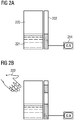
- Fig. 2 shows the falsifying influence of an external disturbance, for example due to the proximity of a laboratory person, on the measurement with a device from the prior art.
- a measuring device which consists of a sensor 202, consisting of a single measuring electrode, and a reference electrode, which is arranged in the vicinity of a container 220 partially filled with a liquid 221. Since the container 220 was previously filled with air, filling the liquid 221 changes the dielectric properties of the immediate vicinity of the sensor, which is expressed in a changed capacitance and thus, for example, in a changed discharge time. A measured value is determined and displayed in the evaluation device 214.
- Figure 2B shows the disturbing influence of the proximity of the hand 222 of a laboratory person. This also changes the dielectric properties of the medium in an area of the container 220 that is not filled with liquid, and the measured value in the evaluation device 214 is falsified. Such a disruptive influence can also be caused by a short circuit or contamination on an electrode.
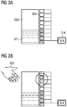
- Fig. 3 shows how the method according to the invention can prevent said error.
- a measuring device which consists of a plurality of measuring electrodes 303 and a reference electrode (not shown) and which is arranged in the vicinity of a container 320 partially filled with a liquid 321. Since the device has more than one measuring electrode 303 and thus more than one electric field, the measured values of the individual measuring electrodes can be subjected to a plausibility check.
- the measuring electrodes from the upper measuring electrodes (circle in Figure 3B ) generated measured values are incorrect because they cannot represent a fill value.
- the evaluation device 314 is able to recognize this and to ignore the relevant measured values.
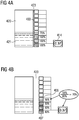
- Fig. 4 shows a measuring device, which consists of ten measuring electrodes 403 and a reference electrode (not shown), and which is arranged in the vicinity of a container 420 partially filled with a liquid 421.
- Figure 4A shows the intended positioning of the device relative to the container 420. The device is only intended to be separated from the container 420 by a slight air gap 423. In this ideal structure, the evaluation device 414 measures a fill level of 37% or 0.37.
- Figure 4B shows a positioning of the device according to the invention relative to the container 420, which results in the device being separated from the container by a wider air gap 423 than intended. This leads to a general reduction in all absolute measured values, so that the lowest measuring electrode 407, which is located below the current liquid level and which should therefore actually generate a full deflection (100%), generates a smaller signal (for example 80%).
- the second and third measuring electrodes from below are also 100% covered by liquid, but only show a measured value of 80%.
- the fourth measuring electrode 406 from below is 70% covered, but only shows a measured value of 56%.
- the evaluation of the absolute measured values would lead to an incorrectly too low level determination.
- a correction factor can be determined, here 80%. All measured values can now be multiplied with this correction factor. In this way, the influence of the air gap is eliminated and the level is correctly determined. In this way, interfering influences can be eliminated, which affect all measuring electrodes equally.
Landscapes
- Physics & Mathematics (AREA)
- Engineering & Computer Science (AREA)
- Power Engineering (AREA)
- Electromagnetism (AREA)
- Thermal Sciences (AREA)
- Fluid Mechanics (AREA)
- General Physics & Mathematics (AREA)
- Measurement Of Levels Of Liquids Or Fluent Solid Materials (AREA)
- Investigating Or Analyzing Materials By The Use Of Electric Means (AREA)
Applications Claiming Priority (1)
| Application Number | Priority Date | Filing Date | Title |
|---|---|---|---|
| DE102010025118A DE102010025118A1 (de) | 2010-06-25 | 2010-06-25 | Berührungslose Füllstandsmessung von Flüssigkeiten |
Publications (2)
| Publication Number | Publication Date |
|---|---|
| EP2400275A1 EP2400275A1 (de) | 2011-12-28 |
| EP2400275B1 true EP2400275B1 (de) | 2021-12-08 |
Family
ID=44513262
Family Applications (1)
| Application Number | Title | Priority Date | Filing Date |
|---|---|---|---|
| EP11169037.6A Active EP2400275B1 (de) | 2010-06-25 | 2011-06-08 | Berührungslose füllstandsmessung von flüssigkeiten |
Country Status (5)
| Country | Link |
|---|---|
| US (1) | US8931340B2 (cg-RX-API-DMAC7.html) |
| EP (1) | EP2400275B1 (cg-RX-API-DMAC7.html) |
| JP (1) | JP5757798B2 (cg-RX-API-DMAC7.html) |
| DE (1) | DE102010025118A1 (cg-RX-API-DMAC7.html) |
| ES (1) | ES2907954T3 (cg-RX-API-DMAC7.html) |
Families Citing this family (52)
| Publication number | Priority date | Publication date | Assignee | Title |
|---|---|---|---|---|
| IT1392525B1 (it) * | 2009-01-08 | 2012-03-09 | Electrolux Home Prod Corp | Procedimento per erogare un liquido in un contenitore e relativo erogatore |
| JP5332989B2 (ja) * | 2009-07-10 | 2013-11-06 | ソニー株式会社 | 液体タンクおよび燃料電池 |
| WO2011073667A1 (en) * | 2009-12-17 | 2011-06-23 | Bae Systems Plc | Sensors |
| SE537311C2 (sv) * | 2011-11-16 | 2015-04-07 | Observe Medical Aps | Anording och metod för detektering av en mätkammares ytdegenerering under mätning av urinproduktion |
| JP5923350B2 (ja) * | 2012-03-15 | 2016-05-24 | 矢崎総業株式会社 | 液面レベル検出装置 |
| DE102014006695A1 (de) * | 2013-05-13 | 2014-11-13 | Hella Kgaa Hueck & Co. | Füllstandssensor zur Messung des Füllstands und Verfahren zur Bestimmung des Füllstands einer Flüssigkeit |
| DE102013112025A1 (de) * | 2013-10-31 | 2015-04-30 | Endress + Hauser Gmbh + Co. Kg | Vorrichtung zur Bestimmung oder Überwachung des Füllstands eines Mediums in einem Behälter |
| US20150129039A1 (en) * | 2013-11-12 | 2015-05-14 | Hamilton Beach Brands, Inc. | Beverage Maker with Capacitance Fluid Level Sensor |
| DE102014210670A1 (de) | 2014-06-05 | 2015-12-17 | BSH Hausgeräte GmbH | Verdampfer |
| US9476752B2 (en) * | 2014-10-01 | 2016-10-25 | Sealed Air Corporation | Fluid level sensor |
| KR20170065535A (ko) * | 2014-10-08 | 2017-06-13 | 세미컨덕터 콤포넨츠 인더스트리즈 엘엘씨 | 레벨 센서 및 방법 |
| US10736357B2 (en) * | 2014-12-25 | 2020-08-11 | Fontem Holdings 1 B.V. | Electronic cigarette liquid detection and measurement systems |
| JP5965012B1 (ja) * | 2015-03-17 | 2016-08-03 | Dmg森精機株式会社 | 液位検出方法及び液位検出装置、並びにこの液位検出装置を備えた工作機械 |
| EP3280469B1 (en) * | 2015-04-08 | 2020-04-29 | ExploraMed NC7, Inc. | Fluid measuring reservoir for breast pumps |
| US9153119B2 (en) * | 2015-04-23 | 2015-10-06 | Scott Stapleford | Scenting nebulizer with remote management and capacitive liquid level sensing |
| ES2675166T3 (es) | 2015-05-27 | 2018-07-09 | Siemens Healthcare Diagnostics Products Gmbh | Recipiente de líquido con un dispositivo anti-salpicaduras |
| EP3121567A1 (de) | 2015-07-22 | 2017-01-25 | Siemens Healthcare Diagnostics Products GmbH | Vorrichtung zur füllstandbestimmung |
| DE102016200762A1 (de) * | 2016-01-20 | 2017-07-20 | BSH Hausgeräte GmbH | Verfahren zur Ermittlung des Füllstands eines entnehmbaren Behälter |
| KR101831964B1 (ko) | 2016-03-08 | 2018-02-23 | 세종공업 주식회사 | 복수 개의 pcb 패드를 이용한 탱크 내부 유체의 수위감지방법 |
| KR101831963B1 (ko) * | 2016-03-08 | 2018-04-04 | 세종공업 주식회사 | 복수 개의 pcb 패드를 이용한 탱크 내부 유체의 수위감지장치 |
| EP3220151A1 (de) | 2016-03-15 | 2017-09-20 | Siemens Healthcare Diagnostics Products GmbH | System zur schaumzerstörung in einem abfallbehälter eines automatischen analysegeräts |
| DE102016123489A1 (de) | 2016-12-05 | 2018-06-07 | Prominent Gmbh | Füllstandssensor |
| KR102286844B1 (ko) * | 2017-02-22 | 2021-08-05 | 현대자동차주식회사 | 정전용량형 수위센서의 수위 출력 방법 |
| EP3367075B1 (en) * | 2017-02-22 | 2019-12-11 | Zodiac Aerotechnics | Capacitor fuel probe |
| WO2018204720A1 (en) * | 2017-05-03 | 2018-11-08 | Nypro Inc. | Apparatus, system, and method of providing a liquid level monitor |
| JP6922412B2 (ja) * | 2017-05-24 | 2021-08-18 | 株式会社リコー | 粉体量検知装置及び画像形成装置 |
| US10254148B2 (en) * | 2017-06-16 | 2019-04-09 | GM Global Technology Operations LLC | Liquid level sensor and method |
| DE102018127458A1 (de) | 2017-11-14 | 2019-05-16 | Miele & Cie. Kg | Verfahren und Steuergerät zum Steuern eines wasserführenden Reinigungsgerätes und Reinigungsgerät |
| DE102017127145B4 (de) * | 2017-11-17 | 2021-03-04 | BEDIA Motorentechnik GmbH & Co. KG | Vorrichtung und Verfahren zur kapazitiven Messung eines Füllstands eines Füllmediums |
| WO2020022982A2 (en) * | 2018-02-08 | 2020-01-30 | Arzum Elektri̇kli̇ Ev Aletleri̇ San. Ve Ti̇c. A.Ş. | An apparatus for sensing liquid level, a device using the said apparatus, and a calibration method |
| US11298297B2 (en) | 2018-03-27 | 2022-04-12 | Zak Wood | Baby bottle sensor with content volume sensing and content deduction logic |
| US10561582B2 (en) | 2018-03-27 | 2020-02-18 | Zak Wood | Baby bottle sensor with content volume sensing and content deduction logic |
| CN112243490A (zh) | 2018-05-03 | 2021-01-19 | 耐普罗公司 | 用于提供固体水平监测器的装置、系统和方法 |
| CN112236654A (zh) | 2018-05-03 | 2021-01-15 | 耐普罗公司 | 用于提供内容物量监视器的装置、系统和方法 |
| DE102018111058A1 (de) | 2018-05-08 | 2019-11-14 | Vega Grieshaber Kg | Impedanzgrenzstandsensor |
| WO2019246476A1 (en) | 2018-06-22 | 2019-12-26 | Bissell Inc. | Apparatus for cleaning a surface |
| EP3594639B1 (de) * | 2018-07-13 | 2022-09-28 | Tecan Trading Ag | Vorrichtung und verfahren zur kapazitiven füllstandsmessung in flüssigkeitsbehältern |
| US11366004B2 (en) * | 2018-07-18 | 2022-06-21 | Mg 2—S.R.L. | Electronic device for detecting the weight of capsules for pharmaceutical products |
| DE102018128723A1 (de) * | 2018-11-15 | 2020-05-20 | Endress+Hauser Conducta Gmbh+Co. Kg | Küvette, vorzugsweise Durchflussküvette für ein optisches Messgerät und Verfahren zu dessen Betrieb |
| JP2020169885A (ja) * | 2019-04-03 | 2020-10-15 | 東芝ライフスタイル株式会社 | 洗濯処理剤収容タンク及び洗濯機 |
| JP7323771B2 (ja) * | 2019-05-31 | 2023-08-09 | 岩崎通信機株式会社 | 対象物検出装置 |
| DE102019129793A1 (de) | 2019-11-05 | 2021-05-06 | Fette Compacting Gmbh | Vorrichtung zum kapazitiven Messen des Pulverfüllstands in einer Fülleinrichtung einer Rundläuferpresse |
| CN111006343A (zh) * | 2019-12-18 | 2020-04-14 | 深圳市晨北科技有限公司 | 一种双水位监测加湿器以及数据处理的方法 |
| WO2022203800A1 (en) * | 2021-03-25 | 2022-09-29 | Cook Medical Technologies Llc | Fill level detection |
| JP2022162489A (ja) * | 2021-04-12 | 2022-10-24 | 株式会社ヨコモリ電池屋コーポレーション | 残量測定値校正機構、噴霧装置 |
| DE102021109944B4 (de) | 2021-04-20 | 2023-02-23 | Fette Compacting Gmbh | System zum kontinuierlichen Verarbeiten von pulverförmigen Produkten |
| CN113237526B (zh) * | 2021-04-22 | 2023-02-24 | 南京信息工程大学 | 一种非接触式液体体积和质量自动测量装置及测量方法 |
| EP4134637B1 (de) * | 2021-08-09 | 2023-08-09 | Rechner Industrie-Elektronik GmbH | Kapazitive füllstandsonde ohne totbereich |
| DE112023003757A5 (de) * | 2022-12-22 | 2025-07-03 | Siemens Aktiengesellschaft | Vorrichtung und Verfahren zur kapazitiven Füllstandmessung |
| DE102023203635A1 (de) | 2023-04-20 | 2024-10-24 | BSH Hausgeräte GmbH | Dampfgargerät, System und Verfahren zum Betreiben des Dampfgargeräts |
| US20250003784A1 (en) * | 2023-06-29 | 2025-01-02 | Microchip Technology Incorporated | Reference measurement technique for capacitive sensing |
| DE102023123925A1 (de) | 2023-09-06 | 2025-03-06 | Miele & Cie. Kg | Haushaltgerät, Verfahren und Steuereinheit zum Betreiben eines Haushaltgeräts |
Citations (4)
| Publication number | Priority date | Publication date | Assignee | Title |
|---|---|---|---|---|
| US4295370A (en) * | 1979-03-12 | 1981-10-20 | Emhart Industries, Inc. | Capacitive scheme for measuring the level of a liquid |
| JPH07128114A (ja) * | 1993-10-29 | 1995-05-19 | Nooken:Kk | レベル測定方法及びレベル測定器 |
| US20030000303A1 (en) * | 2001-06-25 | 2003-01-02 | Livingston Richard A. | Auto-compensating capacitive level sensor |
| DE102007001175A1 (de) * | 2007-01-05 | 2008-07-10 | Siemens Ag | Verfahren und Vorrichtung zur Füllstandsmessung |
Family Cites Families (14)
| Publication number | Priority date | Publication date | Assignee | Title |
|---|---|---|---|---|
| NL8304121A (nl) * | 1983-12-01 | 1985-07-01 | Richard Mulder | Niveaumeter van het capacitieve type. |
| US4749988A (en) * | 1986-11-20 | 1988-06-07 | Imtec Products, Inc. | Non-invasive liquid level sensor |
| US5017909A (en) | 1989-01-06 | 1991-05-21 | Standex International Corporation | Capacitive liquid level sensor |
| US6101873A (en) * | 1996-05-17 | 2000-08-15 | Nohken Inc. | Level sensor |
| US6490920B1 (en) * | 1997-08-25 | 2002-12-10 | Millennium Sensors Ltd. | Compensated capacitive liquid level sensor |
| JPH11311562A (ja) * | 1998-04-27 | 1999-11-09 | Wako:Kk | 水位センサ |
| DE10008093B4 (de) * | 2000-02-22 | 2007-07-05 | Ifm Electronic Gmbh | Kapazitives Füllstandsmessgerät |
| ITPD20010269A1 (it) | 2001-11-20 | 2003-05-20 | Askoll Holding Srl | Dispositivo perfezionato per il rilevamento di livello di liquido particolarmente per pompe sommerse. |
| DE10251716B3 (de) | 2002-11-06 | 2004-08-26 | Siemens Ag | Modellierverfahren für ein Metall |
| DE10261767A1 (de) * | 2002-12-19 | 2004-07-15 | Hydac Electronic Gmbh | Vorrichtung und Verfahren zur Kapazitätsmessung sowie Einrichtung zum Ermitteln des Füllstandes einer Flüssigkeit mit einer solchen Vorrichtung |
| JP2008014617A (ja) * | 2006-07-10 | 2008-01-24 | Miura Co Ltd | 貫流ボイラの水位検出方法及び水位検出装置 |
| EP1961575B1 (en) * | 2007-02-23 | 2011-06-08 | SII Printek Inc | Remaining amount detection sensor and ink-jet printer using the same |
| JP5133667B2 (ja) * | 2007-02-23 | 2013-01-30 | エスアイアイ・プリンテック株式会社 | 残量検知センサおよびそれを用いたインクジェットプリンタ |
| GB0706382D0 (en) * | 2007-04-02 | 2007-05-09 | Huntleigh Technology Plc | Fluid level sensor |
-
2010
- 2010-06-25 DE DE102010025118A patent/DE102010025118A1/de not_active Withdrawn
-
2011
- 2011-06-08 ES ES11169037T patent/ES2907954T3/es active Active
- 2011-06-08 EP EP11169037.6A patent/EP2400275B1/de active Active
- 2011-06-23 US US13/167,219 patent/US8931340B2/en active Active
- 2011-06-23 JP JP2011139503A patent/JP5757798B2/ja active Active
Patent Citations (4)
| Publication number | Priority date | Publication date | Assignee | Title |
|---|---|---|---|---|
| US4295370A (en) * | 1979-03-12 | 1981-10-20 | Emhart Industries, Inc. | Capacitive scheme for measuring the level of a liquid |
| JPH07128114A (ja) * | 1993-10-29 | 1995-05-19 | Nooken:Kk | レベル測定方法及びレベル測定器 |
| US20030000303A1 (en) * | 2001-06-25 | 2003-01-02 | Livingston Richard A. | Auto-compensating capacitive level sensor |
| DE102007001175A1 (de) * | 2007-01-05 | 2008-07-10 | Siemens Ag | Verfahren und Vorrichtung zur Füllstandsmessung |
Also Published As
| Publication number | Publication date |
|---|---|
| ES2907954T3 (es) | 2022-04-27 |
| US8931340B2 (en) | 2015-01-13 |
| EP2400275A1 (de) | 2011-12-28 |
| US20110314907A1 (en) | 2011-12-29 |
| DE102010025118A1 (de) | 2011-12-29 |
| JP5757798B2 (ja) | 2015-07-29 |
| JP2012008129A (ja) | 2012-01-12 |
Similar Documents
| Publication | Publication Date | Title |
|---|---|---|
| EP2400275B1 (de) | Berührungslose füllstandsmessung von flüssigkeiten | |
| EP2994725B1 (de) | Verfahren und vorrichtung zur überwachung zumindest einer medienspezifischen eigenschaft eines mediums für eine füllstandsmessung | |
| EP2962074B1 (de) | Verfahren und vorrichtung zur überwachung eines vorgegebenen füllstands eines mediums in einem behälter | |
| EP3821211B1 (de) | Vorrichtungen und verfahren zur kapazitiven schaumdetektion in flüssigkeitsbehältern | |
| EP2371454B1 (de) | Kapazitives Messverfahren und Vorrichtung zur Füllstandsdetektion und entsprechend ausgestattetes Laborgerät | |
| EP3312571B1 (de) | Impedanzgrenzschalter mit zusätzlicher schirmelektrode | |
| DE102010060465A1 (de) | Verfahren zur Kalibrierung einer Leitfähigkeitsmesszelle | |
| DE102006033112A1 (de) | Verfahren und Einrichtung zum Betrieb eines Durchflussmessgerätes | |
| CH709489B1 (de) | Verfahren zur Durchführung einer kapazitiven Flüssigniveaumessung. | |
| EP4134637B1 (de) | Kapazitive füllstandsonde ohne totbereich | |
| DE10256064A1 (de) | Verfahren und Vorrichtung zur Bestimmung des Wassergehalts und der Leitfähigkeit in Böden und Schüttgütern | |
| DE102005032131A1 (de) | Vorrichtung zur kapazitiven Bestimmung und/oder Überwachung des Füllstandes | |
| EP3652508A1 (de) | Kapazitives messverfahren und füllstandsmessgerät | |
| DE112020002075T5 (de) | Gegenkapazitätsflüssigkeitsmessung mit dualer polarität | |
| EP3594639B1 (de) | Vorrichtung und verfahren zur kapazitiven füllstandsmessung in flüssigkeitsbehältern | |
| EP3153829B1 (de) | Verfahren und vorrichtung zur grenzstandbestimmung | |
| DE10309769B4 (de) | Anordnung zur Bestimmung von Zustandsgrößen für Flüssigkeiten in einem geschlossenen nichtmetallischen Behälter | |
| DE10063557B4 (de) | Verfahren und Vorrichtung zum Messen von Pegelständen | |
| EP1881307A2 (de) | Füllstandssensor für Fluide und/oder Schüttgüter | |
| EP1067368A1 (de) | Pegelstandsmessvorrichtung | |
| EP2735851B1 (de) | Verfahren und Vorrichtung zur kapazitiven Füllstandsmessung mit Kabelsonde oder Stabsonde | |
| DE102016120231A1 (de) | Füllstandsmessgerät für Kleingefäße | |
| CH705731A2 (de) | Vorrichtung und Verfahren zur kapazitiven Bestimmung eines Füllstandes eines Fluids in einem Behälter. | |
| DE2924556A1 (de) | Fuellstandsanzeigeeinrichtung | |
| EP2459974B1 (de) | Vorrichtung und verfahren zur bestimmung einer physikalischen grösse eines kapazitiven näherungsschalters |
Legal Events
| Date | Code | Title | Description |
|---|---|---|---|
| AK | Designated contracting states |
Kind code of ref document: A1 Designated state(s): AL AT BE BG CH CY CZ DE DK EE ES FI FR GB GR HR HU IE IS IT LI LT LU LV MC MK MT NL NO PL PT RO RS SE SI SK SM TR |
|
| AX | Request for extension of the european patent |
Extension state: BA ME |
|
| PUAI | Public reference made under article 153(3) epc to a published international application that has entered the european phase |
Free format text: ORIGINAL CODE: 0009012 |
|
| 17P | Request for examination filed |
Effective date: 20120423 |
|
| STAA | Information on the status of an ep patent application or granted ep patent |
Free format text: STATUS: EXAMINATION IS IN PROGRESS |
|
| 17Q | First examination report despatched |
Effective date: 20180716 |
|
| GRAP | Despatch of communication of intention to grant a patent |
Free format text: ORIGINAL CODE: EPIDOSNIGR1 |
|
| STAA | Information on the status of an ep patent application or granted ep patent |
Free format text: STATUS: GRANT OF PATENT IS INTENDED |
|
| INTG | Intention to grant announced |
Effective date: 20210928 |
|
| GRAS | Grant fee paid |
Free format text: ORIGINAL CODE: EPIDOSNIGR3 |
|
| GRAA | (expected) grant |
Free format text: ORIGINAL CODE: 0009210 |
|
| STAA | Information on the status of an ep patent application or granted ep patent |
Free format text: STATUS: THE PATENT HAS BEEN GRANTED |
|
| AK | Designated contracting states |
Kind code of ref document: B1 Designated state(s): AL AT BE BG CH CY CZ DE DK EE ES FI FR GB GR HR HU IE IS IT LI LT LU LV MC MK MT NL NO PL PT RO RS SE SI SK SM TR |
|
| REG | Reference to a national code |
Ref country code: GB Ref legal event code: FG4D Free format text: NOT ENGLISH |
|
| REG | Reference to a national code |
Ref country code: AT Ref legal event code: REF Ref document number: 1454110 Country of ref document: AT Kind code of ref document: T Effective date: 20211215 Ref country code: CH Ref legal event code: EP |
|
| REG | Reference to a national code |
Ref country code: DE Ref legal event code: R096 Ref document number: 502011017274 Country of ref document: DE |
|
| REG | Reference to a national code |
Ref country code: IE Ref legal event code: FG4D Free format text: LANGUAGE OF EP DOCUMENT: GERMAN |
|
| REG | Reference to a national code |
Ref country code: LT Ref legal event code: MG9D |
|
| REG | Reference to a national code |
Ref country code: NL Ref legal event code: MP Effective date: 20211208 |
|
| REG | Reference to a national code |
Ref country code: ES Ref legal event code: FG2A Ref document number: 2907954 Country of ref document: ES Kind code of ref document: T3 Effective date: 20220427 |
|
| PG25 | Lapsed in a contracting state [announced via postgrant information from national office to epo] |
Ref country code: RS Free format text: LAPSE BECAUSE OF FAILURE TO SUBMIT A TRANSLATION OF THE DESCRIPTION OR TO PAY THE FEE WITHIN THE PRESCRIBED TIME-LIMIT Effective date: 20211208 Ref country code: LT Free format text: LAPSE BECAUSE OF FAILURE TO SUBMIT A TRANSLATION OF THE DESCRIPTION OR TO PAY THE FEE WITHIN THE PRESCRIBED TIME-LIMIT Effective date: 20211208 Ref country code: FI Free format text: LAPSE BECAUSE OF FAILURE TO SUBMIT A TRANSLATION OF THE DESCRIPTION OR TO PAY THE FEE WITHIN THE PRESCRIBED TIME-LIMIT Effective date: 20211208 Ref country code: BG Free format text: LAPSE BECAUSE OF FAILURE TO SUBMIT A TRANSLATION OF THE DESCRIPTION OR TO PAY THE FEE WITHIN THE PRESCRIBED TIME-LIMIT Effective date: 20220308 |
|
| PG25 | Lapsed in a contracting state [announced via postgrant information from national office to epo] |
Ref country code: SE Free format text: LAPSE BECAUSE OF FAILURE TO SUBMIT A TRANSLATION OF THE DESCRIPTION OR TO PAY THE FEE WITHIN THE PRESCRIBED TIME-LIMIT Effective date: 20211208 Ref country code: NO Free format text: LAPSE BECAUSE OF FAILURE TO SUBMIT A TRANSLATION OF THE DESCRIPTION OR TO PAY THE FEE WITHIN THE PRESCRIBED TIME-LIMIT Effective date: 20220308 Ref country code: LV Free format text: LAPSE BECAUSE OF FAILURE TO SUBMIT A TRANSLATION OF THE DESCRIPTION OR TO PAY THE FEE WITHIN THE PRESCRIBED TIME-LIMIT Effective date: 20211208 Ref country code: HR Free format text: LAPSE BECAUSE OF FAILURE TO SUBMIT A TRANSLATION OF THE DESCRIPTION OR TO PAY THE FEE WITHIN THE PRESCRIBED TIME-LIMIT Effective date: 20211208 Ref country code: GR Free format text: LAPSE BECAUSE OF FAILURE TO SUBMIT A TRANSLATION OF THE DESCRIPTION OR TO PAY THE FEE WITHIN THE PRESCRIBED TIME-LIMIT Effective date: 20220309 |
|
| PG25 | Lapsed in a contracting state [announced via postgrant information from national office to epo] |
Ref country code: NL Free format text: LAPSE BECAUSE OF FAILURE TO SUBMIT A TRANSLATION OF THE DESCRIPTION OR TO PAY THE FEE WITHIN THE PRESCRIBED TIME-LIMIT Effective date: 20211208 |
|
| PG25 | Lapsed in a contracting state [announced via postgrant information from national office to epo] |
Ref country code: SM Free format text: LAPSE BECAUSE OF FAILURE TO SUBMIT A TRANSLATION OF THE DESCRIPTION OR TO PAY THE FEE WITHIN THE PRESCRIBED TIME-LIMIT Effective date: 20211208 Ref country code: SK Free format text: LAPSE BECAUSE OF FAILURE TO SUBMIT A TRANSLATION OF THE DESCRIPTION OR TO PAY THE FEE WITHIN THE PRESCRIBED TIME-LIMIT Effective date: 20211208 Ref country code: RO Free format text: LAPSE BECAUSE OF FAILURE TO SUBMIT A TRANSLATION OF THE DESCRIPTION OR TO PAY THE FEE WITHIN THE PRESCRIBED TIME-LIMIT Effective date: 20211208 Ref country code: PT Free format text: LAPSE BECAUSE OF FAILURE TO SUBMIT A TRANSLATION OF THE DESCRIPTION OR TO PAY THE FEE WITHIN THE PRESCRIBED TIME-LIMIT Effective date: 20220408 Ref country code: EE Free format text: LAPSE BECAUSE OF FAILURE TO SUBMIT A TRANSLATION OF THE DESCRIPTION OR TO PAY THE FEE WITHIN THE PRESCRIBED TIME-LIMIT Effective date: 20211208 Ref country code: CZ Free format text: LAPSE BECAUSE OF FAILURE TO SUBMIT A TRANSLATION OF THE DESCRIPTION OR TO PAY THE FEE WITHIN THE PRESCRIBED TIME-LIMIT Effective date: 20211208 |
|
| PG25 | Lapsed in a contracting state [announced via postgrant information from national office to epo] |
Ref country code: PL Free format text: LAPSE BECAUSE OF FAILURE TO SUBMIT A TRANSLATION OF THE DESCRIPTION OR TO PAY THE FEE WITHIN THE PRESCRIBED TIME-LIMIT Effective date: 20211208 |
|
| REG | Reference to a national code |
Ref country code: DE Ref legal event code: R097 Ref document number: 502011017274 Country of ref document: DE |
|
| PG25 | Lapsed in a contracting state [announced via postgrant information from national office to epo] |
Ref country code: IS Free format text: LAPSE BECAUSE OF FAILURE TO SUBMIT A TRANSLATION OF THE DESCRIPTION OR TO PAY THE FEE WITHIN THE PRESCRIBED TIME-LIMIT Effective date: 20220408 |
|
| PLBE | No opposition filed within time limit |
Free format text: ORIGINAL CODE: 0009261 |
|
| STAA | Information on the status of an ep patent application or granted ep patent |
Free format text: STATUS: NO OPPOSITION FILED WITHIN TIME LIMIT |
|
| PG25 | Lapsed in a contracting state [announced via postgrant information from national office to epo] |
Ref country code: DK Free format text: LAPSE BECAUSE OF FAILURE TO SUBMIT A TRANSLATION OF THE DESCRIPTION OR TO PAY THE FEE WITHIN THE PRESCRIBED TIME-LIMIT Effective date: 20211208 Ref country code: AL Free format text: LAPSE BECAUSE OF FAILURE TO SUBMIT A TRANSLATION OF THE DESCRIPTION OR TO PAY THE FEE WITHIN THE PRESCRIBED TIME-LIMIT Effective date: 20211208 |
|
| 26N | No opposition filed |
Effective date: 20220909 |
|
| PG25 | Lapsed in a contracting state [announced via postgrant information from national office to epo] |
Ref country code: SI Free format text: LAPSE BECAUSE OF FAILURE TO SUBMIT A TRANSLATION OF THE DESCRIPTION OR TO PAY THE FEE WITHIN THE PRESCRIBED TIME-LIMIT Effective date: 20211208 |
|
| PG25 | Lapsed in a contracting state [announced via postgrant information from national office to epo] |
Ref country code: MC Free format text: LAPSE BECAUSE OF FAILURE TO SUBMIT A TRANSLATION OF THE DESCRIPTION OR TO PAY THE FEE WITHIN THE PRESCRIBED TIME-LIMIT Effective date: 20211208 |
|
| REG | Reference to a national code |
Ref country code: BE Ref legal event code: MM Effective date: 20220630 |
|
| PG25 | Lapsed in a contracting state [announced via postgrant information from national office to epo] |
Ref country code: LU Free format text: LAPSE BECAUSE OF NON-PAYMENT OF DUE FEES Effective date: 20220608 Ref country code: IE Free format text: LAPSE BECAUSE OF NON-PAYMENT OF DUE FEES Effective date: 20220608 |
|
| PG25 | Lapsed in a contracting state [announced via postgrant information from national office to epo] |
Ref country code: BE Free format text: LAPSE BECAUSE OF NON-PAYMENT OF DUE FEES Effective date: 20220630 |
|
| REG | Reference to a national code |
Ref country code: AT Ref legal event code: MM01 Ref document number: 1454110 Country of ref document: AT Kind code of ref document: T Effective date: 20220608 |
|
| PG25 | Lapsed in a contracting state [announced via postgrant information from national office to epo] |
Ref country code: AT Free format text: LAPSE BECAUSE OF NON-PAYMENT OF DUE FEES Effective date: 20220608 |
|
| PGFP | Annual fee paid to national office [announced via postgrant information from national office to epo] |
Ref country code: IT Payment date: 20230627 Year of fee payment: 13 Ref country code: ES Payment date: 20230918 Year of fee payment: 13 |
|
| PG25 | Lapsed in a contracting state [announced via postgrant information from national office to epo] |
Ref country code: HU Free format text: LAPSE BECAUSE OF FAILURE TO SUBMIT A TRANSLATION OF THE DESCRIPTION OR TO PAY THE FEE WITHIN THE PRESCRIBED TIME-LIMIT; INVALID AB INITIO Effective date: 20110608 |
|
| PG25 | Lapsed in a contracting state [announced via postgrant information from national office to epo] |
Ref country code: MK Free format text: LAPSE BECAUSE OF FAILURE TO SUBMIT A TRANSLATION OF THE DESCRIPTION OR TO PAY THE FEE WITHIN THE PRESCRIBED TIME-LIMIT Effective date: 20211208 Ref country code: CY Free format text: LAPSE BECAUSE OF FAILURE TO SUBMIT A TRANSLATION OF THE DESCRIPTION OR TO PAY THE FEE WITHIN THE PRESCRIBED TIME-LIMIT Effective date: 20211208 |
|
| PG25 | Lapsed in a contracting state [announced via postgrant information from national office to epo] |
Ref country code: TR Free format text: LAPSE BECAUSE OF FAILURE TO SUBMIT A TRANSLATION OF THE DESCRIPTION OR TO PAY THE FEE WITHIN THE PRESCRIBED TIME-LIMIT Effective date: 20211208 |
|
| PG25 | Lapsed in a contracting state [announced via postgrant information from national office to epo] |
Ref country code: MT Free format text: LAPSE BECAUSE OF FAILURE TO SUBMIT A TRANSLATION OF THE DESCRIPTION OR TO PAY THE FEE WITHIN THE PRESCRIBED TIME-LIMIT Effective date: 20211208 |
|
| PG25 | Lapsed in a contracting state [announced via postgrant information from national office to epo] |
Ref country code: IT Free format text: LAPSE BECAUSE OF NON-PAYMENT OF DUE FEES Effective date: 20240608 |
|
| PGFP | Annual fee paid to national office [announced via postgrant information from national office to epo] |
Ref country code: FR Payment date: 20250613 Year of fee payment: 15 |
|
| REG | Reference to a national code |
Ref country code: ES Ref legal event code: FD2A Effective date: 20250729 |
|
| PG25 | Lapsed in a contracting state [announced via postgrant information from national office to epo] |
Ref country code: ES Free format text: LAPSE BECAUSE OF NON-PAYMENT OF DUE FEES Effective date: 20240609 |
|
| PGFP | Annual fee paid to national office [announced via postgrant information from national office to epo] |
Ref country code: DE Payment date: 20250820 Year of fee payment: 15 |
|
| PGFP | Annual fee paid to national office [announced via postgrant information from national office to epo] |
Ref country code: GB Payment date: 20250710 Year of fee payment: 15 |
|
| PGFP | Annual fee paid to national office [announced via postgrant information from national office to epo] |
Ref country code: CH Payment date: 20250903 Year of fee payment: 15 |