EP2400275B1 - Contactless fill level measurement of liquids - Google Patents
Contactless fill level measurement of liquids Download PDFInfo
- Publication number
- EP2400275B1 EP2400275B1 EP11169037.6A EP11169037A EP2400275B1 EP 2400275 B1 EP2400275 B1 EP 2400275B1 EP 11169037 A EP11169037 A EP 11169037A EP 2400275 B1 EP2400275 B1 EP 2400275B1
- Authority
- EP
- European Patent Office
- Prior art keywords
- measurement
- electrodes
- container
- electrode
- measuring
- Prior art date
- Legal status (The legal status is an assumption and is not a legal conclusion. Google has not performed a legal analysis and makes no representation as to the accuracy of the status listed.)
- Active
Links
- 238000005259 measurement Methods 0.000 title claims description 76
- 239000007788 liquid Substances 0.000 title description 20
- 238000000034 method Methods 0.000 claims description 27
- 239000003990 capacitor Substances 0.000 claims description 26
- 238000011156 evaluation Methods 0.000 claims description 24
- 230000005684 electric field Effects 0.000 claims description 14
- 238000012937 correction Methods 0.000 claims description 6
- 230000002596 correlated effect Effects 0.000 claims 2
- 239000000463 material Substances 0.000 description 7
- 239000000523 sample Substances 0.000 description 6
- 230000008859 change Effects 0.000 description 5
- 239000000126 substance Substances 0.000 description 5
- 230000008901 benefit Effects 0.000 description 4
- UHOVQNZJYSORNB-UHFFFAOYSA-N Benzene Chemical compound C1=CC=CC=C1 UHOVQNZJYSORNB-UHFFFAOYSA-N 0.000 description 3
- OKKJLVBELUTLKV-UHFFFAOYSA-N Methanol Chemical compound OC OKKJLVBELUTLKV-UHFFFAOYSA-N 0.000 description 3
- 238000013459 approach Methods 0.000 description 3
- 230000000694 effects Effects 0.000 description 3
- XLYOFNOQVPJJNP-UHFFFAOYSA-N water Substances O XLYOFNOQVPJJNP-UHFFFAOYSA-N 0.000 description 3
- QGZKDVFQNNGYKY-UHFFFAOYSA-N Ammonia Chemical compound N QGZKDVFQNNGYKY-UHFFFAOYSA-N 0.000 description 2
- LFQSCWFLJHTTHZ-UHFFFAOYSA-N Ethanol Chemical compound CCO LFQSCWFLJHTTHZ-UHFFFAOYSA-N 0.000 description 2
- PEDCQBHIVMGVHV-UHFFFAOYSA-N Glycerine Chemical compound OCC(O)CO PEDCQBHIVMGVHV-UHFFFAOYSA-N 0.000 description 2
- -1 Polypropylene Polymers 0.000 description 2
- WCUXLLCKKVVCTQ-UHFFFAOYSA-M Potassium chloride Chemical compound [Cl-].[K+] WCUXLLCKKVVCTQ-UHFFFAOYSA-M 0.000 description 2
- 238000009530 blood pressure measurement Methods 0.000 description 2
- 230000007423 decrease Effects 0.000 description 2
- 239000011521 glass Substances 0.000 description 2
- 229910052751 metal Inorganic materials 0.000 description 2
- 239000002184 metal Substances 0.000 description 2
- 239000013610 patient sample Substances 0.000 description 2
- 230000002093 peripheral effect Effects 0.000 description 2
- 239000007787 solid Substances 0.000 description 2
- 239000002023 wood Substances 0.000 description 2
- RYGMFSIKBFXOCR-UHFFFAOYSA-N Copper Chemical compound [Cu] RYGMFSIKBFXOCR-UHFFFAOYSA-N 0.000 description 1
- 239000004698 Polyethylene Substances 0.000 description 1
- 239000004743 Polypropylene Substances 0.000 description 1
- 229910021529 ammonia Inorganic materials 0.000 description 1
- 239000013590 bulk material Substances 0.000 description 1
- 238000004891 communication Methods 0.000 description 1
- 239000004020 conductor Substances 0.000 description 1
- 238000011109 contamination Methods 0.000 description 1
- 239000011889 copper foil Substances 0.000 description 1
- 230000001419 dependent effect Effects 0.000 description 1
- 238000013461 design Methods 0.000 description 1
- 239000012777 electrically insulating material Substances 0.000 description 1
- 230000005672 electromagnetic field Effects 0.000 description 1
- 239000000945 filler Substances 0.000 description 1
- 239000007789 gas Substances 0.000 description 1
- 235000011187 glycerol Nutrition 0.000 description 1
- 230000002452 interceptive effect Effects 0.000 description 1
- 238000000691 measurement method Methods 0.000 description 1
- 239000007769 metal material Substances 0.000 description 1
- 239000000203 mixture Substances 0.000 description 1
- 238000012544 monitoring process Methods 0.000 description 1
- 230000003287 optical effect Effects 0.000 description 1
- 239000003960 organic solvent Substances 0.000 description 1
- 239000012188 paraffin wax Substances 0.000 description 1
- 238000005192 partition Methods 0.000 description 1
- 230000035699 permeability Effects 0.000 description 1
- 239000004033 plastic Substances 0.000 description 1
- 229920003023 plastic Polymers 0.000 description 1
- 230000010287 polarization Effects 0.000 description 1
- 229920000573 polyethylene Polymers 0.000 description 1
- 229920001155 polypropylene Polymers 0.000 description 1
- 235000011164 potassium chloride Nutrition 0.000 description 1
- 239000001103 potassium chloride Substances 0.000 description 1
- 239000000843 powder Substances 0.000 description 1
- 230000008569 process Effects 0.000 description 1
- BDERNNFJNOPAEC-UHFFFAOYSA-N propan-1-ol Chemical compound CCCO BDERNNFJNOPAEC-UHFFFAOYSA-N 0.000 description 1
- 230000009467 reduction Effects 0.000 description 1
- 238000005070 sampling Methods 0.000 description 1
- 230000035945 sensitivity Effects 0.000 description 1
- 238000012360 testing method Methods 0.000 description 1
- 238000002604 ultrasonography Methods 0.000 description 1
- 238000010200 validation analysis Methods 0.000 description 1
Images

Classifications
-
- G—PHYSICS
- G01—MEASURING; TESTING
- G01F—MEASURING VOLUME, VOLUME FLOW, MASS FLOW OR LIQUID LEVEL; METERING BY VOLUME
- G01F23/00—Indicating or measuring liquid level or level of fluent solid material, e.g. indicating in terms of volume or indicating by means of an alarm
- G01F23/22—Indicating or measuring liquid level or level of fluent solid material, e.g. indicating in terms of volume or indicating by means of an alarm by measuring physical variables, other than linear dimensions, pressure or weight, dependent on the level to be measured, e.g. by difference of heat transfer of steam or water
- G01F23/26—Indicating or measuring liquid level or level of fluent solid material, e.g. indicating in terms of volume or indicating by means of an alarm by measuring physical variables, other than linear dimensions, pressure or weight, dependent on the level to be measured, e.g. by difference of heat transfer of steam or water by measuring variations of capacity or inductance of capacitors or inductors arising from the presence of liquid or fluent solid material in the electric or electromagnetic fields
- G01F23/263—Indicating or measuring liquid level or level of fluent solid material, e.g. indicating in terms of volume or indicating by means of an alarm by measuring physical variables, other than linear dimensions, pressure or weight, dependent on the level to be measured, e.g. by difference of heat transfer of steam or water by measuring variations of capacity or inductance of capacitors or inductors arising from the presence of liquid or fluent solid material in the electric or electromagnetic fields by measuring variations in capacitance of capacitors
- G01F23/268—Indicating or measuring liquid level or level of fluent solid material, e.g. indicating in terms of volume or indicating by means of an alarm by measuring physical variables, other than linear dimensions, pressure or weight, dependent on the level to be measured, e.g. by difference of heat transfer of steam or water by measuring variations of capacity or inductance of capacitors or inductors arising from the presence of liquid or fluent solid material in the electric or electromagnetic fields by measuring variations in capacitance of capacitors mounting arrangements of probes
Definitions
- the present invention relates to a method for non-invasive, non-contact capacitive fill level measurement.
- level measurements With level measurements, the level (the level) of liquids and bulk solids in a container is recorded using level measuring devices.
- a float with a float is placed in a vessel with a liquid.
- This float contains, for example, a magnet whose field is actuated through the vessel wall by magnetic relays which are arranged as an array. This means that the level in the vessel can be measured.
- the problem here is that, depending on the density of the liquid, the float is immersed differently, which falsifies the measurement result. In these devices, too, the swimmer inevitably comes into contact with the liquid, which can result in the latter becoming contaminated or the swimmer - depending on the properties of the liquid - being affected by it.
- level measurement examples include conductivity measurement, pressure measurement, measurement with ultrasound (in which the level is determined by the signal propagation time), weight measurement of the container, differential pressure measurement, optical measurement or capacity measurement.
- the dielectric conductivity ⁇ of the product which is different from that of gases or air, is used.
- a probe located inside the container and, for example, the electrically conductive container wall form an electrical capacitor. If the probe is in air, a certain low initial capacitance is measured. If the container is filled, the capacity of the capacitor increases as the probe is covered.
- Probe electronics convert the capacitance into an electrical pulse train and amplify it. Evaluation electronics calculate the measured value from the pulse rate. The change in capacity of the medium is converted into a signal proportional to the level and enables the level to be displayed.
- This method has the disadvantage that the probe, just like the above-mentioned swimmer, can be affected by the liquid, depending on the properties of the liquid. Furthermore, if the container is part of a system, there is a risk that the probe will be mechanically or electrically damaged every time the container is changed.
- capacitive sensors can also be used in methods for non-invasive capacitive level measurement. These methods are characterized by the fact that no part of the fill level sensor comes into contact with the fill medium whose fill level is to be determined.
- the active surface of a capacitive sensor contains electrodes, with the help of which the dielectric conditions in the environment can be perceived.
- the sensor comprises two electrodes which are arranged, as it were, on an unfolded plate capacitor. A high-frequency alternating electric field is generated between these electrodes. This field penetrates the material to be measured non-destructively.
- the capacitance of the capacitor depends on the permittivity of the filler material.
- the term "permittivity" also: dielectric conductivity, symbol: ⁇ gives the Permeability of a material to electric fields.
- a permittivity is also assigned to the vacuum, since electric fields can also develop in the vacuum or electromagnetic fields can propagate.
- the dimensionless quantity ⁇ r characterizes the field-weakening effects of the dielectric polarization within electrically insulating materials and is closely related to the electrical susceptibility ⁇ .
- the term "dielectric constant" for permittivity is considered obsolete and should no longer be used.
- capacitive sensors are able to react without contact - i.e. without direct contact - to the approach of an object with an electrical switching signal. Since capacitive sensors can also detect through non-metallic partition walls in this way, they are particularly suitable for level monitoring of liquids, pastes or bulk goods.
- the ohmic discharge current between individual electrodes of the capacitor is usually measured.
- the capacitor is connected in series with an alternating current milliammeter to an alternating voltage source.
- the current I then flowing and displayed by the instrument depends on the capacitive resistance of the capacitor. A measurement frequency is so low for this to choose that the ohmic resistance is dominant compared to the capacitive current in both media.
- a counter that produces a counting event can be activated, or the elapsed time is output as a measured value.
- the procedure for non-invasive, capacitive level measurement is as follows: If one of the electrodes is, for example, adjacent to a medium with low permittivity, such as air, a low initial capacitance is measured first. If the container is filled with a medium of higher permittivity, such as water, the capacitance of the capacitor increases as the area around the capacitor electrode increases. As described above, a measured value can then be tapped which is proportional to the area adjacent to the capacitor electrode.
- CLC Capacitive Level Sensor
- sensors of this type are also susceptible to other external influences. For example, an air gap between the measuring field and the measuring container reduces the measuring signal.
- the level sensor is part of a system, e.g. an automatic analyzer for examining clinical patient samples, this incorrect measurement can lead to considerable complications in the course of further work steps.
- a device that is less susceptible to interference from external influences would therefore be of great advantage.
- the device for contactless capacitive fill level measurement has a special arrangement of at least two measuring electrodes and at least one reference electrode.
- the invention therefore relates to a method according to claim 1 using a device for non-invasive capacitive fill level measurement.
- the electrical fields formed between the measuring electrodes and the reference electrode can, provided the device is attached to a container, penetrate the container wall non-destructively and can be measurably influenced by the fill level of the filling medium.
- electric field is intended to denote an invisible force field that is formed by mutually attractive and repulsive electrical charges.
- the unit of electric field strength is volts per meter (V / m), and the strength of an electric field decreases with increasing distance from the source.
- the capacitance of the capacitor depends on the permittivity of the substance between the plates. Therefore, when an object is approached or removed, which has a different permittivity than the substance originally located between the plates, the capacitance of the capacitor changes. As a result, when the container is filled or emptied, the electrodes are influenced by the filling medium in such a way that the capacitance of the capacitor that they form changes.
- the term "filling medium" is intended to designate the substance whose fill level is to be determined.
- the filling medium is preferably a liquid, a paste or a bulk material.
- the term "container” is intended to denote a vessel in which the filling medium to be measured is located.
- the container is preferably a canister, tub or bottle.
- measuring electrode is intended to denote an electrode which, together with the reference electrode, forms a capacitor.
- the total area of all measuring electrodes of a device defines the measuring area of the device.
- reference electrode is intended to denote an electrode which, together with one or with several or with all measuring electrodes, forms a capacitor in each case.
- the reference electrode also serves as a reference point for continuous measurement.
- the two-dimensional extension of the reference electrode or the total area of all reference electrodes of a device defines the reference surface of the device.
- the device has at least two reference electrodes which define the reference surface.
- the reference electrodes are then arranged in different horizontal planes, so that a reference electrode on a horizontal plane and a measuring electrode on the same horizontal plane each form a capacitor.
- the device can have at least 3, preferably at least 5, very particularly preferably at least 10 measuring electrodes.
- the device can have 3, 4, 5, 6, 7, 8, 9 or 10 measuring electrodes, but in principle any number of measuring electrodes ⁇ 2 is conceivable.
- the reference and measuring electrodes consist of an electrically conductive material, preferably a metallic material, for example a copper foil.
- the measuring electrodes can have the same or different sizes and / or configurations. In principle, the design and dimensions of the measuring electrodes are irrelevant. For example, they can be oval, circular, square or rectangular. The dimensions appropriately depend on the size of the container in which the Filling medium is located, the level of which is to be determined, together.
- the measuring electrodes are preferably each designed rectangular with a size of 50 ⁇ 18 mm or 35 ⁇ 12 mm.
- the at least two measuring electrodes preferably have areas of different sizes. This has the advantage that the filling level can be measured at different points on the container with different degrees of accuracy. If, for example, the residual content of a filling medium in a container is to be determined with the non-contact capacitive level measurement, the size of the measuring electrodes could decrease towards the bottom of the container in order to ensure an ever more accurate measurement result.
- the dimension of the reference area which is formed by one or more reference electrodes, is selected so that its vertical extent corresponds to at least the vertical extent of the measurement area, which is defined by the vertical arrangement of the measurement electrodes, or goes beyond it.
- the device is designed in such a way that, in order to determine the fill level, it measures the capacitances of at least two capacitors and relates them to one another.
- the device preferably also comprises an evaluation device.
- This sets the measured values in relation to one another in such a way that external influences affect all Electrodes have the same effect, so that the measurement result is only minimally affected. This is done, for example, by a ratio determination and / or a plausibility check.
- evaluation device is intended to denote a device that measures the change in the capacitance of the electric fields and calculates the level. The measurement can be made in Farads. Alternatively, however, the measured value can also be other variables that serve as a measure for a change in capacitance.
- the measured value obtained by measuring the at least two capacities and then calculating them is preferably displayed as a unit-free measured value (e.g. in percent).
- the evaluation device also enables the measured values to be validated by comparing them with stored calibration values and by comparing the measured values with one another.
- the evaluation device can be present as a separate device, but it can also be part of a higher-level control system.
- the evaluation device preferably has a main processor (CPU) and / or a programmable logic controller (PLC).
- CPU main processor
- PLC programmable logic controller
- the device is preferably in contact with a higher-level control system.
- the device preferably has a serial interface (serial peripheral interface, for example RS-232 or RS-485) as a further component.
- the device can have a voltage source. The presence of these additional components has the advantage that the device can be used as desired as an independent component.
- the device is preferably part of an analysis system, for example an automatic analysis device for examining clinical patient samples, in which other operations depend on the result of the level measurement.
- the higher-level control system monitors the individual processes in the analyzer and coordinates them with one another.
- the evaluation device of the device is part of the superordinate control system.
- the device is preferably not arranged directly on the container, but on a holding device which enables the device for level measurement to be positioned at a fixed distance from the container. This enables the container to be exchanged without any problems without the risk of damaging the evaluation device.
- the device is suitable for the contactless measurement of the fill level of a wide variety of filling media, such as water, organic solvents or bulk materials such as powder or granular solids.
- filling media such as water, organic solvents or bulk materials such as powder or granular solids.
- all possible filling media can be used that have a permittivity that differs so clearly from the permittivity of the material that is in the container before filling or after removing the filling medium that the change in capacity when filling the The container or when emptying the container fails so clearly that the evaluation device can determine the fill level.
- the device is suitable for the non-contact measurement of the fill level of filling media in a wide variety of containers.
- a container can at least partially consist of a material from the group of glass, plastic and wood.
- the container can have any volume between about 500 mL and about 20 L.
- the container is preferably part of the device and the reference electrode is formed by part of the container wall.
- the container wall must be at least partially electrically conductive, at least in the area that is provided as a reference surface.
- the measuring electrodes Depending on the height of the container, the measuring electrodes have a different surface area or it becomes a larger one or a smaller number of measuring electrodes are used to provide a measuring surface that covers the level-relevant height of the container.
- At least two calibration values which are determined by measuring an empty and a full container, are required.
- a measured value that is falsified by a local air gap between the container and the device on the affected measuring electrode can be compensated for.
- the robustness of the fill level measurement according to the invention against external influences is preferably thereby achieved reinforces the fact that when more than two measuring electrodes are used, a plausibility check can be carried out in which the data from those measuring electrodes which obviously generate an incorrect measured value are ignored during the evaluation.
- the interconnection of the electrodes enables a meaningful self-test to be carried out on the device, which greatly reduces incorrect measurements.
- the capacitances of the at least two capacitors are measured continuously.
- the validation of the measured values includes a ratio measurement.
- the measured values of the at least two measuring electrodes are compared with one another and related to one another.
- the individual absolute raw values are not decisive for the measurement, but the relative values that result from the comparison with other measured values.
- the so-called ratio measurement is in Fig. 4 shown.
- a device with 10 measuring electrodes is attached to a container.
- the fill level of the medium in the container is such that the three lowest measuring electrodes are completely covered, i.e. 100%, and the fourth measuring electrode from below is covered by 70%. This covers 37% of the measuring area, resulting in a level of 37% or 0.37. If, for example, there is a larger air gap between the measuring electrodes and the container, the measuring electrodes measure lower absolute raw values.
- a correction factor is determined using a measuring electrode that is completely covered, and all measured values from the other measuring electrodes are multiplied by this correction factor. In this way the influence of the air gap is eliminated. This way can too The influence of filling media with non-constant dielectric values can be minimized if, for example, the properties of the filling medium to be measured are not known (unknown liquid mixtures).
- the required calibration values are preferably determined by measuring a container once when it is empty and once when it is filled with the corresponding filling medium.
- the method according to the invention preferably also includes a plausibility check, the individual absolute measured values of the measuring electrodes being checked by means of a logical evaluation.
- a device with 10 measuring electrodes attached to a container the comparison of the measured value of the fourth measuring electrode from below with the third measuring electrode from below shows that the measured value of the fourth electrode is lower than the measured value of the third electrode. If the comparison of the fifth measuring electrode from below with the fourth measuring electrode from below shows that the measured value of the fifth electrode would be higher than the measured value of the fourth electrode, this would be implausible, since a higher-lying measuring electrode cannot be covered more by the filling medium than another measuring electrode located below.
- the evaluation device thus recognizes that one of the two measured values must be implausible and therefore faulty.
- an incorrect measurement e.g. due to a short-term or local interference (air gap, Approach of an object) can be recognized and displayed.
- the incorrect measured value can be ignored during the fill level measurement.
- Fig. 1 shows a schematic representation of a top view of a device 100.
- the device comprises a serial interface (serial peripheral interface) 101, a voltage regulator 102, 10 measuring electrodes (103 to 112), a reference electrode 113 and an evaluation device 114, here a CPU.
- the measuring electrodes are each connected to the reference electrode 113, so that each measuring electrode 103-112 together with the reference electrode 113 each forms a capacitor. Consequently, the electric fields whose capacitances are measured are in each case between a measuring electrode and the reference electrode 113. In the present case there are a total of 10 electric fields, the capacities of which can change depending on the fill level of a filling medium.
- the evaluation device 114 preferably carries out a plausibility check during the fill level measurement.
- the changes in capacitance are determined, for example, by initially calculating the measurement data from the individual measurement electrodes 103-112. Here it could emerge, for example, that the measuring electrodes 112 to 109 are below the fill level, whereas measuring electrodes 107 to 103 are above the fill level. The measuring electrode 108 is exactly at the level of the fill level.
- the evaluation device determines whether one of the measuring electrodes is outputting an implausible measurement result. This could happen, for example, if an object is located in the electric field of the measuring electrode 104 and causes a capacitance that cannot be reconciled with the measurement result of the neighboring measuring electrodes 103 and 105.
- the measurement result of the neighboring measurement electrodes 103 and 105 makes it clear that all three measurement electrodes 103, 104 and 105 are above the fill level and the capacitance of the electrodes should be similar. By taking this information into account, the evaluation device can differentiate between correct and incorrect measurement results and correctly calculate the fill level.
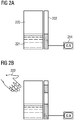
- Fig. 2 shows the falsifying influence of an external disturbance, for example due to the proximity of a laboratory person, on the measurement with a device from the prior art.
- a measuring device which consists of a sensor 202, consisting of a single measuring electrode, and a reference electrode, which is arranged in the vicinity of a container 220 partially filled with a liquid 221. Since the container 220 was previously filled with air, filling the liquid 221 changes the dielectric properties of the immediate vicinity of the sensor, which is expressed in a changed capacitance and thus, for example, in a changed discharge time. A measured value is determined and displayed in the evaluation device 214.
- Figure 2B shows the disturbing influence of the proximity of the hand 222 of a laboratory person. This also changes the dielectric properties of the medium in an area of the container 220 that is not filled with liquid, and the measured value in the evaluation device 214 is falsified. Such a disruptive influence can also be caused by a short circuit or contamination on an electrode.
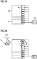
- Fig. 3 shows how the method according to the invention can prevent said error.
- a measuring device which consists of a plurality of measuring electrodes 303 and a reference electrode (not shown) and which is arranged in the vicinity of a container 320 partially filled with a liquid 321. Since the device has more than one measuring electrode 303 and thus more than one electric field, the measured values of the individual measuring electrodes can be subjected to a plausibility check.
- the measuring electrodes from the upper measuring electrodes (circle in Figure 3B ) generated measured values are incorrect because they cannot represent a fill value.
- the evaluation device 314 is able to recognize this and to ignore the relevant measured values.
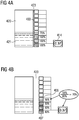
- Fig. 4 shows a measuring device, which consists of ten measuring electrodes 403 and a reference electrode (not shown), and which is arranged in the vicinity of a container 420 partially filled with a liquid 421.
- Figure 4A shows the intended positioning of the device relative to the container 420. The device is only intended to be separated from the container 420 by a slight air gap 423. In this ideal structure, the evaluation device 414 measures a fill level of 37% or 0.37.
- Figure 4B shows a positioning of the device according to the invention relative to the container 420, which results in the device being separated from the container by a wider air gap 423 than intended. This leads to a general reduction in all absolute measured values, so that the lowest measuring electrode 407, which is located below the current liquid level and which should therefore actually generate a full deflection (100%), generates a smaller signal (for example 80%).
- the second and third measuring electrodes from below are also 100% covered by liquid, but only show a measured value of 80%.
- the fourth measuring electrode 406 from below is 70% covered, but only shows a measured value of 56%.
- the evaluation of the absolute measured values would lead to an incorrectly too low level determination.
- a correction factor can be determined, here 80%. All measured values can now be multiplied with this correction factor. In this way, the influence of the air gap is eliminated and the level is correctly determined. In this way, interfering influences can be eliminated, which affect all measuring electrodes equally.
Description
Die vorliegende Erfindung bezieht sich auf ein Verfahren zur nicht-invasiven, berührungslosen kapazitiven Füllstandsmessung.The present invention relates to a method for non-invasive, non-contact capacitive fill level measurement.
Bei Füllstandsmessungen wird der Füllstand (die Standhöhe) von Flüssigkeiten und Schüttgütern in einem Behälter mittels Füllstandsmessgeräten erfasst.With level measurements, the level (the level) of liquids and bulk solids in a container is recorded using level measuring devices.
Bei einer klassischen Füllstandsmessmethode wird ein Schwimmer mit einem Schwimmkörper in ein Gefäß mit einer Flüssigkeit eingebracht. Dieser Schwimmer enthält beispielsweise einen Magneten, dessen Feld durch die Gefäßwand Magnetrelais betätigt, welche als Array angeordnet sind. Dadurch ist der Füllstand im Gefäß messbar. Problematisch ist hierbei, dass je nach Dichte der Flüssigkeit der Schwimmkörper verschieden weit eintaucht, was das Messergebnis verfälscht. Auch kommt bei diesen Vorrichtungen der Schwimmer zwangsläufig mit der Flüssigkeit in Kontakt, was zur Folge haben kann, dass diese verunreinigt wird oder dass der Schwimmer -je nach Eigenschaft der Flüssigkeit- von dieser in Mitleidenschaft gezogen wird.In a classic level measurement method, a float with a float is placed in a vessel with a liquid. This float contains, for example, a magnet whose field is actuated through the vessel wall by magnetic relays which are arranged as an array. This means that the level in the vessel can be measured. The problem here is that, depending on the density of the liquid, the float is immersed differently, which falsifies the measurement result. In these devices, too, the swimmer inevitably comes into contact with the liquid, which can result in the latter becoming contaminated or the swimmer - depending on the properties of the liquid - being affected by it.
Weitere bekannte Methoden zur Füllstandsmessung umfassen die Leitfähigkeitsmessung, Druckmessung, Messung mit Ultraschall (bei welcher die Füllhöhe durch die Signallaufzeit ermittelt wird), Gewichtsmessung des Behälters, Differenzdruckmessung, optische Messung oder Kapazitätsmessung.Further known methods for level measurement include conductivity measurement, pressure measurement, measurement with ultrasound (in which the level is determined by the signal propagation time), weight measurement of the container, differential pressure measurement, optical measurement or capacity measurement.
Bei der kapazitiven Füllstandsmessung wird die gegenüber Gasen oder Luft unterschiedliche dielektrische Leitfähigkeit ε des Füllguts ausgenutzt.With capacitive level measurement, the dielectric conductivity ε of the product, which is different from that of gases or air, is used.
Bei invasiven Methoden der kapazitiven Füllstandsmessung bilden eine im Inneren des Behälters befindliche Sonde und z.B. die elektrisch leitende Behälterwand einen elektrischen Kondensator. Befindet sich die Sonde in Luft, wird eine bestimmte niedrige Anfangskapazität gemessen. Wird der Behälter befüllt, so steigt mit zunehmender Bedeckung der Sonde die Kapazität des Kondensators. Eine Sondenelektronik wandelt die Kapazität in eine elektrische Impulsfolge um und verstärkt sie. Eine Auswerteelektronik berechnet aus der Impulsrate den Messwert. Die Kapazitätsänderung des Mediums wird zu einem dem Füllstand proportionalen Signal umgewandelt und ermöglicht die Anzeige des Füllstandes.In the case of invasive methods of capacitive level measurement, a probe located inside the container and, for example, the electrically conductive container wall form an electrical capacitor. If the probe is in air, a certain low initial capacitance is measured. If the container is filled, the capacity of the capacitor increases as the probe is covered. Probe electronics convert the capacitance into an electrical pulse train and amplify it. Evaluation electronics calculate the measured value from the pulse rate. The change in capacity of the medium is converted into a signal proportional to the level and enables the level to be displayed.
Diese Methode weist den Nachteil auf, dass die Sonde, genau wie der oben erwähnte Schwimmer, je nach Eigenschaft der Flüssigkeit von dieser in Mitleidenschaft gezogen werden kann. Ferner besteht, falls der Behälter Teil eines Systems ist, bei jedem Wechsel des Behälters die Gefahr, dass die Sonde mechanisch oder elektrisch beschädigt wird.This method has the disadvantage that the probe, just like the above-mentioned swimmer, can be affected by the liquid, depending on the properties of the liquid. Furthermore, if the container is part of a system, there is a risk that the probe will be mechanically or electrically damaged every time the container is changed.
Weiterhin können kapazitive Sensoren auch bei Methoden zur nicht-invasiven kapazitiven Füllstandsmessung eingesetzt werden. Diese Methoden zeichnen sich dadurch aus, dass kein Teil des Füllstandssensors mit dem Füllmedium, dessen Füllhöhe ermittelt werden soll, in Berührung kommt.Furthermore, capacitive sensors can also be used in methods for non-invasive capacitive level measurement. These methods are characterized by the fact that no part of the fill level sensor comes into contact with the fill medium whose fill level is to be determined.
Die aktive Fläche eines kapazitiven Sensors enthält Elektroden, mit deren Hilfe die dielektrischen Verhältnisse in der Umgebung wahrgenommen werden. Beispielsweise umfasst der Sensor zwei Elektroden, die gleichsam einem aufgeklapptem Plattenkondensator angeordnet sind. Zwischen diesen Elektroden wird ein hochfrequentes elektrisches Wechselfeld erzeugt. Dieses Feld durchdringt das zu messende Material zerstörungsfrei.The active surface of a capacitive sensor contains electrodes, with the help of which the dielectric conditions in the environment can be perceived. For example, the sensor comprises two electrodes which are arranged, as it were, on an unfolded plate capacitor. A high-frequency alternating electric field is generated between these electrodes. This field penetrates the material to be measured non-destructively.
Die Kapazität des Kondensators hängt von der Permittivität des Füllmaterials ab. Der Begriff "Permittivität" (auch: dielektrische Leitfähigkeit, Formelzeichen: ε) gibt die Durchlässigkeit eines Materials für elektrische Felder an. Auch dem Vakuum ist eine Permittivität zugewiesen, da sich auch im Vakuum elektrische Felder einstellen oder elektromagnetische Felder ausbreiten können.The capacitance of the capacitor depends on the permittivity of the filler material. The term "permittivity" (also: dielectric conductivity, symbol: ε) gives the Permeability of a material to electric fields. A permittivity is also assigned to the vacuum, since electric fields can also develop in the vacuum or electromagnetic fields can propagate.
Die Permittivitätszahl (relative Permittivität) εr = ε/ε0 ist das Verhältnis von ε zur elektrischen Feldkonstante ε0 (Permittivität des Vakuums). Die dimensionslose Größe εr kennzeichnet die feldschwächenden Effekte der dielektrischen Polarisation innerhalb elektrisch isolierender Materialien und hängt eng mit der elektrischen Suszeptibilität χ zusammen. Die Bezeichnung "Dielektrizitätskonstante" für Permittivität gilt als veraltet und sollte nicht mehr verwendet werden.The permittivity number (relative permittivity) ε r = ε / ε0 is the ratio of ε to the electric field constant ε0 (permittivity of the vacuum). The dimensionless quantity ε r characterizes the field-weakening effects of the dielectric polarization within electrically insulating materials and is closely related to the electrical susceptibility χ. The term "dielectric constant" for permittivity is considered obsolete and should no longer be used.
Da die meisten Medien eine von Luft oder Vakuum verschiedene Permittivität besitzen, führt das Befüllen eines Gefäßes, an dem sich ein kapazitiver Füllstandssensor befindet, zu einem Anstieg der Kapazität zwischen den Elektroden.Since most media have a different permittivity than air or vacuum, filling a vessel with a capacitive level sensor leads to an increase in the capacitance between the electrodes.
Es wird also ausgenutzt, dass, sobald sich ein leitendes oder nicht-leitendes Objekt annähert, sich je nach Abstand und Material des Messobjekts die elektrische Kapazität der Messelektrode zur Umgebung oder zu einer Referenzelektrode ändert. Somit sind kapazitive Sensoren in der Lage, berührungsfrei - d.h. ohne direkten Kontakt - auf Annäherung eines Objekts mit einem elektrischen Schaltsignal zu reagieren. Da kapazitive Sensoren auf diese Weise auch durch nicht-metallische Trennwände hindurch detektieren können, eignen sie sich besonders zur Füllstandsüberwachung von Flüssigkeiten, Pasten oder Schüttgütern.This makes use of the fact that as soon as a conductive or non-conductive object approaches, the electrical capacitance of the measuring electrode to the environment or to a reference electrode changes depending on the distance and material of the measuring object. This means that capacitive sensors are able to react without contact - i.e. without direct contact - to the approach of an object with an electrical switching signal. Since capacitive sensors can also detect through non-metallic partition walls in this way, they are particularly suitable for level monitoring of liquids, pastes or bulk goods.
Zur Bestimmung der Kapazität eines Kondensators wird in der Regel der ohmsche Entladestrom zwischen einzelnen Elektroden des Kondensators gemessen. Dabei wird der Kondensator in Reihe mit einem Wechselstrom-Milliamperemeter an eine Wechselspannungsquelle geschaltet. Der dann fließende und vom Instrument angezeigte Strom I hängt vom kapazitiven Widerstand des Kondensators ab. Hierfür ist eine Messfrequenz so niedrig zu wählen, dass in beiden Medien der ohmsche Widerstand gegenüber dem kapazitiven Strom dominant ist.To determine the capacitance of a capacitor, the ohmic discharge current between individual electrodes of the capacitor is usually measured. The capacitor is connected in series with an alternating current milliammeter to an alternating voltage source. The current I then flowing and displayed by the instrument depends on the capacitive resistance of the capacitor. A measurement frequency is so low for this to choose that the ohmic resistance is dominant compared to the capacitive current in both media.
Alternativ ist es möglich, die Zeit zu messen, in welcher die Spannung am Kondensator auf einen bestimmten Wert (beispielsweise 33 %) gefallen ist. Nach Ablauf dieser Zeit kann beispielsweise ein Zähler angesteuert werden, der ein Zählereignis produziert, oder es wird die abgelaufene Zeit als Messwert ausgegeben.Alternatively, it is possible to measure the time in which the voltage across the capacitor has dropped to a certain value (for example 33%). After this time has elapsed, for example, a counter that produces a counting event can be activated, or the elapsed time is output as a measured value.
Zur nicht-invasiven, kapazitiven Füllstandsmessung wird dabei wie folgt vorgegangen: Befindet sich eine der Elektroden beispielsweise benachbart zu einem Medium mit geringer Permittivität, wie z.B. Luft, wird zunächst eine niedrige Anfangskapazität gemessen. Wird der Behälter mit einem Medium höherer Permittivität, wie z.B. Wasser, befüllt, so steigt mit zunehmendem Benachbarungsbereich der Kondensatorelektrode die Kapazität des Kondensators. Es kann dann wie oben beschrieben ein Messwert abgegriffen werden, der proportional zum Benachbarungsbereich der Kondensatorelektrode ist.The procedure for non-invasive, capacitive level measurement is as follows: If one of the electrodes is, for example, adjacent to a medium with low permittivity, such as air, a low initial capacitance is measured first. If the container is filled with a medium of higher permittivity, such as water, the capacitance of the capacitor increases as the area around the capacitor electrode increases. As described above, a measured value can then be tapped which is proportional to the area adjacent to the capacitor electrode.
Ein Beispiel für einen kapazitiven Sensor, der für die Füllstandsmessung eingesetzt wird, ist der Sensor "CLC" (Capacitive Level Sensor) der Firma Sensortechnics (http://www.sensortechnics.com/download/DS_Standard-CLC_E_11663.pdf). Dieser Sensor verfügt über eine einzige Messelektrode und eine einzige Referenzelektrode und wird an der Außenseite einer Behälterwand befestigt.An example of a capacitive sensor that is used for level measurement is the "CLC" (Capacitive Level Sensor) sensor from Sensortechnics (http://www.sensortechnics.com/download/DS_Standard-CLC_E_11663.pdf). This sensor has a single measuring electrode and a single reference electrode and is attached to the outside of a container wall.
Nachteilig bei diesem Sensor und anderen bekannten Verfahren und den dazu gehörigen Vorrichtungen ist jedoch die Empfindlichkeit für äußere Störeinflüsse, die das Messergebnis verfälschen können. Störende Einflüsse können z.B. von hochfrequenten Spannungsquellen, vom Bedienungspersonal oder anderen, räumlich eng benachbarten Flüssigkeitsbehältern mit variablem Füllstand ausgehen. Insbesondere in Laboren mit mehreren, räumlich eng benachbart angeordneten Apparaturen und automatischen Analysegeräten, bei denen hochfrequente Spannungsquellen eingesetzt werden, treten derartige äußere Störungen mit großer Wahrscheinlichkeit, relativ häufig und massiv auf. Ein solcher Sensor, der an einem (fast) leeren Behälter befestigt ist, zeigt z.B. fälschlicherweise an, dass der Behälter voll oder teilweise gefüllt ist, wenn ein Objekt, z.B. eine Hand oder ein Maschinenteil, in die Nähe der Messelektrode gerät.However, a disadvantage of this sensor and other known methods and the associated devices is the sensitivity to external interference which can falsify the measurement result. Disturbing influences can come from high-frequency voltage sources, from the operating personnel or from other, spatially closely spaced liquid containers with a variable fill level. Particularly in laboratories with several apparatus and automatic analysis devices that are spatially closely spaced and in which high-frequency If voltage sources are used, such external disturbances occur with great probability, relatively frequently and massively. Such a sensor, which is attached to an (almost) empty container, falsely indicates, for example, that the container is full or partially full if an object, for example a hand or a machine part, comes near the measuring electrode.
Zudem sind Sensoren dieser Art auch für andere Einflüsse von außen anfällig. So bewirkt zum Beispiel ein Luftspalt zwischen Messfeld und Messbehälter eine Verringerung des Messsignals.In addition, sensors of this type are also susceptible to other external influences. For example, an air gap between the measuring field and the measuring container reduces the measuring signal.
Wenn der Füllstandssensor Teil eines Systems ist, z.B. eines automatischen Analysegerätes für die Untersuchung von klinischen Patientenproben, kann diese Fehlmessung zu erheblichen Komplikationen im Ablauf von weiteren Arbeitsschritten führen.If the level sensor is part of a system, e.g. an automatic analyzer for examining clinical patient samples, this incorrect measurement can lead to considerable complications in the course of further work steps.
Zudem hängt bei derartigen Sensoren die Messgenauigkeit sehr stark von einer korrekten Kalibrierung ab, wodurch es zu erheblichen Messfehlern kommen kann und die Benutzerfreundlichkeit stark eingeschränkt ist.In addition, the measurement accuracy of such sensors depends very much on a correct calibration, which can lead to considerable measurement errors and the user-friendliness is severely restricted.
Daher wäre eine Vorrichtung, die weniger störanfällig für äußere Einflüsse ist, von großem Vorteil.A device that is less susceptible to interference from external influences would therefore be of great advantage.
Zudem wäre eine Vorrichtung, deren Messqualität weniger von der Qualität der Kalibrierung abhängt, von großem Vorteil.In addition, a device whose measurement quality is less dependent on the quality of the calibration would be of great advantage.
In
Die
Es ist eine Aufgabe der vorliegenden Erfindung, ein Verfahren zur berührungslosen kapazitiven Füllstandsmessung eines Füllmediums in einem Behälter bereitzustellen, welches die oben genannten Nachteile vermeidet und die insbesondere weniger störungsanfällig für Einflüsse von außen ist.It is an object of the present invention to provide a method for contactless capacitive fill level measurement of a fill medium in a container, which the avoids the disadvantages mentioned above and which in particular is less susceptible to interference from outside influences.
Die Aufgabe wird unter anderem dadurch gelöst, dass die Vorrichtung zur berührungslosen kapazitiven Füllstandsmessung eine besondere Anordnung von mindestens zwei Messlektroden und mindestens einer Referenzelektrode aufweist.The object is achieved, inter alia, in that the device for contactless capacitive fill level measurement has a special arrangement of at least two measuring electrodes and at least one reference electrode.
Die Erfindung betrifft daher ein Verfahren gemäß Patentanspruch 1 unter Verwendung einer Vorrichtung zur nicht-invasiven kapazitiven Füllstandsmessung.The invention therefore relates to a method according to claim 1 using a device for non-invasive capacitive fill level measurement.
Die zwischen den Messelektroden und der Referenzelektrode ausgebildeten elektrischen Felder können, sofern die Vorrichtung an einem Behälter angebracht ist, die Behälterwand zerstörungsfrei durchdringen und durch den Füllstand des Füllmediums messbar beeinflusst werden.The electrical fields formed between the measuring electrodes and the reference electrode can, provided the device is attached to a container, penetrate the container wall non-destructively and can be measurably influenced by the fill level of the filling medium.
-
Fig. 1 zeigt eine schematische Darstellung einer bevorzugten Ausführungsform einer das erfindungsgemäße Verfahren durchführenden Vorrichtung.Fig. 1 shows a schematic representation of a preferred embodiment of a device carrying out the method according to the invention. -
Fig. 2 ,3 und4 veranschaulichen, wie das erfindungsgemäße Verfahren Messfehler unterdrücken kann.Fig. 2 ,3 and4th illustrate how the method according to the invention can suppress measurement errors.
Der Begriff "elektrisches Feld" soll ein unsichtbares Kraftfeld, das durch sich gegenseitig anziehende und abstoßende elektrische Ladungen gebildet wird, bezeichnen. Die Einheit der elektrischen Feldstärke ist Volt pro Meter (V/m), und die Stärke eines elektrischen Feldes nimmt mit zunehmender Entfernung von der Quelle ab.The term "electric field" is intended to denote an invisible force field that is formed by mutually attractive and repulsive electrical charges. The unit of electric field strength is volts per meter (V / m), and the strength of an electric field decreases with increasing distance from the source.
Die Kapazität des Kondensators hängt von der Permittivität des Stoffes zwischen den Platten ab. Daher ändert sich bei Annäherung bzw. Entfernung eines Objektes, welches eine andere Permittivität als der ursprünglich zwischen den Platten befindlichen Stoff besitzt, die Kapazität des Kondensators. Folglich werden die Elektroden beim Befüllen oder Leeren des Behälters durch das Füllmedium so beeinflusst, dass sich die Kapazität des Kondensators, den sie bilden, ändert.The capacitance of the capacitor depends on the permittivity of the substance between the plates. Therefore, when an object is approached or removed, which has a different permittivity than the substance originally located between the plates, the capacitance of the capacitor changes. As a result, when the container is filled or emptied, the electrodes are influenced by the filling medium in such a way that the capacitance of the capacitor that they form changes.
Der Begriff "Füllmedium" soll den Stoff, dessen Füllstand ermittelt werden soll, bezeichnen. Vorzugsweise ist das Füllmedium eine Flüssigkeit, eine Paste oder ein Schüttgut.The term "filling medium" is intended to designate the substance whose fill level is to be determined. The filling medium is preferably a liquid, a paste or a bulk material.
Der Begriff "Behälter" soll ein Gefäß bezeichnen, in dem sich das zu vermessende Füllmedium befindet. Vorzugsweise handelt es sich bei dem Behälter um einen Kanister, eine Wanne oder Flasche.The term "container" is intended to denote a vessel in which the filling medium to be measured is located. The container is preferably a canister, tub or bottle.
Der Begriff "Messelektrode" soll eine Elektrode bezeichnen, die zusammen mit der Referenzelektrode jeweils einen Kondensator ausbildet. Die Gesamtfläche aller Messelektroden einer Vorrichtung definiert die Messfläche der Vorrichtung.The term “measuring electrode” is intended to denote an electrode which, together with the reference electrode, forms a capacitor. The total area of all measuring electrodes of a device defines the measuring area of the device.
Der Begriff "Referenzelektrode" soll im Folgenden eine Elektrode bezeichnen, die zusammen mit einer oder mit mehreren oder mit allen Messelektroden jeweils einen Kondensator ausbildet. Zudem dient die Referenzelektrode auch als Bezugspunkt für die kontinuierliche Messung. Die zweidimensionale Ausdehnung der Referenzelektrode bzw. Gesamtfläche aller Referenzelektroden einer Vorrichtung definiert die Referenzfläche der Vorrichtung.The term “reference electrode” is intended to denote an electrode which, together with one or with several or with all measuring electrodes, forms a capacitor in each case. In addition, the reference electrode also serves as a reference point for continuous measurement. The two-dimensional extension of the reference electrode or the total area of all reference electrodes of a device defines the reference surface of the device.
Die Vorrichtung weist mindestens zwei Referenzelektroden auf, die die Referenzfläche definieren. Die Referenzelektroden sind dann in unterschiedlichen horizontalen Ebenen angeordnet, so dass eine Referenzelektrode auf einer horizontalen Ebene mit einer Messelektrode auf derselben horizontalen Ebene jeweils einen Kondensator ausbildet.The device has at least two reference electrodes which define the reference surface. The reference electrodes are then arranged in different horizontal planes, so that a reference electrode on a horizontal plane and a measuring electrode on the same horizontal plane each form a capacitor.
Die Vorrichtung kann mindestens 3, bevorzugterweise mindestens 5, ganz besonders bevorzugt mindestens 10 Messelektroden aufweisen. Die Vorrichtung kann 3, 4, 5, 6, 7, 8, 9 oder 10 Messelektroden aufweisen, grundsätzlich ist jedoch jede Anzahl an Messelektroden ≥ 2 denkbar.The device can have at least 3, preferably at least 5, very particularly preferably at least 10 measuring electrodes. The device can have 3, 4, 5, 6, 7, 8, 9 or 10 measuring electrodes, but in principle any number of measuring electrodes ≥ 2 is conceivable.
Die Referenz- und Messelektroden bestehen aus einem elektrisch leitfähigen, bevorzugt aus einem metallischen Material, beispielsweise aus einer Kupferfolie. Die Messelektroden können dieselbe oder unterschiedliche Größen und/oder Ausgestaltungen aufweisen. Grundsätzlich spielen die Ausgestaltung und die Dimensionen der Messelektroden keine Rolle. Sie können beispielsweise oval, kreisrund, quadratisch oder rechteckig ausgestaltet sein. Die Dimensionen hängen zweckmäßig mit der Größe des Behälters, in dem sich das Füllmedium befindet, dessen Füllstand bestimmt werden soll, zusammen.The reference and measuring electrodes consist of an electrically conductive material, preferably a metallic material, for example a copper foil. The measuring electrodes can have the same or different sizes and / or configurations. In principle, the design and dimensions of the measuring electrodes are irrelevant. For example, they can be oval, circular, square or rectangular. The dimensions appropriately depend on the size of the container in which the Filling medium is located, the level of which is to be determined, together.
Bevorzugterweise sind die Messelektroden jeweils rechteckig ausgestaltet mit einer Größe von 50 × 18 mm oder 35 × 12 mm.The measuring electrodes are preferably each designed rectangular with a size of 50 × 18 mm or 35 × 12 mm.
Bevorzugterweise weisen die mindestens zwei Messelektroden unterschiedlich große Flächen auf. Dies hat den Vorteil, dass der Füllstand an unterschiedlichen Stellen des Behälters mit unterschiedlicher Genauigkeit gemessen werden kann. Wenn mit der berührungslosen kapazitiven Füllstandsmessung beispielsweise insbesondere der Restgehalt eines Füllmediums in einem Behälter bestimmt werden soll, könnte die Größe der Messelektroden zum Boden des Behälters hin abnehmen, um ein immer genaueres Messergebnis zu gewährleisten.The at least two measuring electrodes preferably have areas of different sizes. This has the advantage that the filling level can be measured at different points on the container with different degrees of accuracy. If, for example, the residual content of a filling medium in a container is to be determined with the non-contact capacitive level measurement, the size of the measuring electrodes could decrease towards the bottom of the container in order to ensure an ever more accurate measurement result.
Die Dimension der Referenzfläche, die durch eine oder mehrere Referenzelektroden gebildet wird, ist so gewählt, dass sie in ihrer vertikalen Ausdehnung mindestens der vertikalen Ausdehnung der Messfläche, die durch die vertikale Anordnung der Messelektroden definiert ist, entspricht oder über sie hinaus geht.The dimension of the reference area, which is formed by one or more reference electrodes, is selected so that its vertical extent corresponds to at least the vertical extent of the measurement area, which is defined by the vertical arrangement of the measurement electrodes, or goes beyond it.
Es wurde überraschenderweise gefunden, dass durch die Verwendung mehrerer Messelektroden, die zusammen mit einer Referenzelektrode jeweils einen Kondensator ausbilden, der störende Einfluss äußerer Störfaktoren vermindert und die oben genannten Messverfälschungen vermieden werden können. Die Vorrichtung ist nämlich so ausgestaltet, dass sie zur Bestimmung des Füllstandes die Kapazitäten von mindestens zwei Kondensatoren misst und zueinander in Beziehung setzt.It has surprisingly been found that the use of several measuring electrodes, each of which forms a capacitor together with a reference electrode, reduces the disruptive influence of external interference factors and the above-mentioned measurement errors can be avoided. The device is designed in such a way that, in order to determine the fill level, it measures the capacitances of at least two capacitors and relates them to one another.
Bevorzugterweise umfasst die Vorrichtung ferner eine Auswerteeinrichtung. Diese setzt die Messwerte so zueinander in Beziehung, dass sich äußere Einflüsse auf alle Elektroden gleich auswirken, so dass das Messergebnis nur minimal beeinträchtigt wird. Dies geschieht beispielsweise durch eine Ratioermittlung und/oder eine Plausibilitätprüfung. Der Begriff "Auswerteeinrichtung" soll eine Einrichtung bezeichnen, die die Veränderung der Kapazität der elektrischen Felder misst und den Füllstand berechnet. Die Messung kann in Farad erfolgen. Alternativ kann es sich bei dem Messwert aber auch um andere Größen handeln, die als Maß für eine Kapazitätsänderung dienen.The device preferably also comprises an evaluation device. This sets the measured values in relation to one another in such a way that external influences affect all Electrodes have the same effect, so that the measurement result is only minimally affected. This is done, for example, by a ratio determination and / or a plausibility check. The term "evaluation device" is intended to denote a device that measures the change in the capacitance of the electric fields and calculates the level. The measurement can be made in Farads. Alternatively, however, the measured value can also be other variables that serve as a measure for a change in capacitance.
Bevorzugterweise wird der sich durch die Messung der mindestens zwei Kapazitäten und anschließende Verrechnung erhaltene Messwert als einheitenloser Messwert dargestellt (z.B. in Prozent). Die Auswerteeinrichtung ermöglicht ferner die Validierung der Messwerte durch Vergleich mit gespeicherten Kalibrierungswerten und durch Vergleich der Messwerte untereinander.The measured value obtained by measuring the at least two capacities and then calculating them is preferably displayed as a unit-free measured value (e.g. in percent). The evaluation device also enables the measured values to be validated by comparing them with stored calibration values and by comparing the measured values with one another.
Die Auswerteeinrichtung kann als separate Einrichtung vorliegen, sie kann aber auch Teil eines übergeordneten Steuersystems sein.The evaluation device can be present as a separate device, but it can also be part of a higher-level control system.
Bevorzugterweise weist die Auswerteeinrichtung einen Hauptprozessor (CPU) und/oder eine Speicherprogrammierbare Steuerung (SPS) auf.The evaluation device preferably has a main processor (CPU) and / or a programmable logic controller (PLC).
Die Vorrichtung steht bevorzugterweise in Kontakt mit einem übergeordneten Steuersystem. Zur Herstellung einer Kommunikation mit einem übergeordneten Steuersystem weist die Vorrichtung bevorzugterweise eine serielle Schnittstelle (Serial Periphal Interface, z.B. RS-232 oder RS-485) als weitere Komponente auf. Ferner kann die Vorrichtung eine Spannungsquelle aufweisen. Das Vorhandensein dieser weiteren Komponenten hat den Vorteil, dass die Vorrichtung als eigenständiges Bauteil beliebig eingesetzt werden kann.The device is preferably in contact with a higher-level control system. To establish communication with a higher-level control system, the device preferably has a serial interface (serial peripheral interface, for example RS-232 or RS-485) as a further component. Furthermore, the device can have a voltage source. The presence of these additional components has the advantage that the device can be used as desired as an independent component.
Bevorzugterweise ist die Vorrichtung Teil eines Analysesystems, z.B. eines automatischen Analysegerätes für die Untersuchung von klinischen Patientenproben, in dem andere Arbeitsgänge von dem Ergebnis der Füllstandsmessung abhängen. Das übergeordnete Steuersystem überwacht die einzelnen Abläufe im Analysegerät und stimmt sie aufeinander ab. In einer bevorzugten Ausführungsform ist die Auswerteeinrichtung der Vorrichtung Teil des übergeordneten Steuersystems.The device is preferably part of an analysis system, for example an automatic analysis device for examining clinical patient samples, in which other operations depend on the result of the level measurement. The higher-level control system monitors the individual processes in the analyzer and coordinates them with one another. In a preferred embodiment, the evaluation device of the device is part of the superordinate control system.
Bevorzugterweise ist die Vorrichtung nicht direkt am Behälter angeordnet, sondern an einer Haltevorrichtung, die eine Positionierung der Vorrichtung zur Füllstandsmessung in festgelegtem Abstand zum Behälter ermöglicht. Dies ermöglicht, dass der Behälter problemlos, ohne die Gefahr einer Beschädigung der Auswertevorrichtung ausgetauscht werden kann.The device is preferably not arranged directly on the container, but on a holding device which enables the device for level measurement to be positioned at a fixed distance from the container. This enables the container to be exchanged without any problems without the risk of damaging the evaluation device.
Die Vorrichtung eignet sich zur berührungslosen Messung des Füllstands von verschiedensten Füllmedien, wie beispielsweise von Wasser, organischen Lösungsmitteln oder Schüttgütern, wie pulver- oder granulatförmigen Feststoffen. Grundsätzlich können jedoch alle möglichen Füllmedien verwendet werden, die eine Permittivität aufweisen, die sich von der Permittivität des Materials, das sich vor dem Einfüllen bzw. nach dem Entfernen des Füllmediums im Behälter befindet, so deutlich unterscheidet, dass die Änderung der Kapazität beim Befüllen des Behälters bzw. beim Entleeren des Behälters so deutlich ausfällt, dass die Auswerteeinrichtung den Füllstand ermitteln kann.The device is suitable for the contactless measurement of the fill level of a wide variety of filling media, such as water, organic solvents or bulk materials such as powder or granular solids. In principle, however, all possible filling media can be used that have a permittivity that differs so clearly from the permittivity of the material that is in the container before filling or after removing the filling medium that the change in capacity when filling the The container or when emptying the container fails so clearly that the evaluation device can determine the fill level.
Die folgende Tabelle zeigt relative Permittivitäten einiger Stoffe bei 18 °C und einer Frequenz von 50 Hz.
Die Vorrichtung eignet sich zur berührungslosen Messung des Füllstands von Füllmedien in verschiedensten Behältern. Ein Behälter kann zumindest teilweise aus einem Material der Gruppe Glas, Kunststoff und Holz bestehen. Der Behälter kann ein beliebiges Volumen von zwischen etwa 500 mL und etwa 20 L aufweisen.The device is suitable for the non-contact measurement of the fill level of filling media in a wide variety of containers. A container can at least partially consist of a material from the group of glass, plastic and wood. The container can have any volume between about 500 mL and about 20 L.
Bevorzugterweise ist der Behälter ein Bestandteil der Vorrichtung und die Referenzelektrode wird durch einen Teil der Behälterwand gebildet. In diesem Fall muss die Behälterwand zumindest in dem Bereich, der als Referenzfläche vorgesehen ist, zumindest teilweise elektrisch leitend sein.The container is preferably part of the device and the reference electrode is formed by part of the container wall. In this case, the container wall must be at least partially electrically conductive, at least in the area that is provided as a reference surface.
Je nach Höhe des Behälters weisen die Messelektroden eine unterschiedliche große Fläche auf, oder es wird eine größere bzw. kleinere Anzahl von Messelektroden verwendet, um eine Messfläche bereit zu stellen, die die Füllstands-relevante Höhe des Behälters überdeckt.Depending on the height of the container, the measuring electrodes have a different surface area or it becomes a larger one or a smaller number of measuring electrodes are used to provide a measuring surface that covers the level-relevant height of the container.
Damit der Füllstand des Füllmediums korrekt bestimmt werden kann, werden mindestens zwei Kalibrierwerte, die durch Vermessung eines leeren und eines vollen Behälters ermittelt werden, benötigt.In order that the filling level of the filling medium can be correctly determined, at least two calibration values, which are determined by measuring an empty and a full container, are required.
Dadurch, dass die Messwerte der einzelnen Messelektroden nicht direkt zur Berechnung des Füllstands verwendet werden, sondern mit gespeicherten Kalibrierungswerten und untereinander verglichen werden, wirkt sich ein äußerer Einfluss, der die gesamte Vorrichtung betrifft, nur sehr gering auf die Füllstandsmessung aus, da der äußere Einfluss alle Elektroden gleichermaßen beeinträchtigt.Because the measured values of the individual measuring electrodes are not used directly to calculate the level, but are compared with stored calibration values and with each other, an external influence that affects the entire device has only a very slight effect on the level measurement, since the external influence affects all electrodes equally.
Beispielsweise kann ein Messwert, der durch einen lokalen Luftspalt zwischen Behälter und Vorrichtung an der betroffenen Messelektrode verfälscht wird, ausgeglichen werden. Zusätzlich wird die Robustheit der erfindungsgemäßen Füllstandsmessung gegen äußere Einflüsse vorzugsweise dadurch verstärkt, dass bei der Verwendung von mehr als zwei Messelektroden, eine Plausibilitätsprüfung durchgeführt werden kann, in der Daten von denjenigen Messelektroden, die offensichtlich einen fehlerhaften Messwert generieren, bei der Auswertung ignoriert werden.For example, a measured value that is falsified by a local air gap between the container and the device on the affected measuring electrode can be compensated for. In addition, the robustness of the fill level measurement according to the invention against external influences is preferably thereby achieved reinforces the fact that when more than two measuring electrodes are used, a plausibility check can be carried out in which the data from those measuring electrodes which obviously generate an incorrect measured value are ignored during the evaluation.
Zudem ermöglicht die Verknüpfung der Elektroden untereinander die Durchführung eines aussagekräftigen Selbsttests der Vorrichtung, wodurch Fehlmessungen stark minimiert werden können.In addition, the interconnection of the electrodes enables a meaningful self-test to be carried out on the device, which greatly reduces incorrect measurements.
In einer bevorzugten Ausführungsform werden die Kapazitäten der mindestens zwei Kondensatoren kontinuierlich gemessen. Der Begriff "kontinuierlich" soll im Folgenden eine stetige Messung bezeichnen, die entweder in analoger Weise durchgeführt wird, oder aber in digitaler Weise mit einer hohen Samplingrate (= "pseudokontinuierlich").In a preferred embodiment, the capacitances of the at least two capacitors are measured continuously. The term “continuous” is intended to denote a continuous measurement in the following, which is either carried out in an analog manner or in a digital manner with a high sampling rate (= “pseudo-continuous”).
Erfindungsgemäß umfasst die Validierung der Messwerte eine Ratiomessung. Dabei werden die Messwerte der mindestens zwei Messelektroden untereinander verglichen und zueinander in Beziehung gesetzt. Maßgeblich für die Messung sind also nicht die einzelnen absoluten Rohwerte, sondern die relativen Werte, die sich durch den Vergleich mit weiteren Messwerten ergeben. Die sog. Ratiomessung ist in
Die benötigten Kalibrierungswerte werden bevorzugt durch Vermessen eines Behälters einmal im leeren und einmal im mit dem entsprechenden Füllmedium befüllten Zustand ermittelt. Es ist jedoch auch möglich, dass zur Ermittlung der Kalibrierungswerte nicht derselbe Behälter einmal im vollen und einmal im leeren Zustand vermessen wird, sondern zwei baugleiche Behälter vermessen werden, von denen einer leer und einer voll ist. Bei keinem der für die Kalibrierung verwendeten Behälter muss es sich um den Behälter handeln, der das Füllmedium enthält, es muss jedoch ein genügend ähnlicher Behälter sein, damit der Füllstand mit den ermittelten Kalibrierdaten anschließend korrekt bestimmt werden kann.The required calibration values are preferably determined by measuring a container once when it is empty and once when it is filled with the corresponding filling medium. However, it is also possible for the determination of the calibration values not to measure the same container once when it is full and once when it is empty, but instead to measure two structurally identical containers, one of which is empty and one of which is full. None of the containers used for calibration has to be the container that contains the filling medium, but it must be a sufficiently similar container so that the filling level can then be correctly determined with the determined calibration data.
Bevorzugterweise umfasst das erfindungsgemäße Verfahren ferner eine Plausibilitätsprüfung, wobei die einzelnen absoluten Messwerte der Messelektroden mittels einer logischen Auswertung überprüft werden. Ist, wie z.B. in
Alternativ kann, wenn sich herausstellt, dass der Wert einer einzigen Messelektrode fehlerhaft ist und dass genügend andere, plausible Messwerte vorliegen, der fehlerhafte Messwert bei der Füllstandsmessung ignoriert werden.Alternatively, if it turns out that the value of a single measuring electrode is incorrect and that there are enough other, plausible measured values, the incorrect measured value can be ignored during the fill level measurement.
Neben der Ermittlung der Kapazitätsänderungen führt die Auswerteeinrichtung 114 während der Füllstandsmessung bevorzugt eine Plausibilitätsprüfung durch.In addition to determining the changes in capacitance, the
Die Ermittlung der Kapazitätsänderungen erfolgt beispielsweise, indem zunächst die Messdaten der einzelnen Messelektroden 103-112 verrechnet werden. Hier könnte sich zum Beispiel ergeben, dass die Messelektroden 112 bis 109 unterhalb des Füllstands liegen, wohingegen Messelektroden 107 bis 103 oberhalb des Füllstands liegen. Die Messelektrode 108 liegt genau auf der Höhe des Füllstands.The changes in capacitance are determined, for example, by initially calculating the measurement data from the individual measurement electrodes 103-112. Here it could emerge, for example, that the measuring
Bei der Plausibilitätsprüfung ermittelt die Auswerteeinrichtung, ob eine der Messelektroden ein nicht plausibles Messergebnis ausgibt. Dies könnte zum Beispiel passieren, wenn sich ein Objekt im elektrischen Feld der Messelektrode 104 befindet und eine Kapazität verursacht, die sich nicht mit dem Messergebnis der benachbarten Messelektroden 103 und 105 in Einklang bringen lässt. Das Messergebnis der benachbarten Messelektroden 103 und 105 stellt klar, dass alle drei Messelektroden 103, 104 und 105 oberhalb des Füllstands liegen und die Kapazität der Elektroden ähnlich sein sollte. Durch Berücksichtigen dieser Information kann die Auswerteeinrichtung korrekte von falschen Messergebnissen unterscheiden und den Füllstand richtig berechnen.During the plausibility check, the evaluation device determines whether one of the measuring electrodes is outputting an implausible measurement result. This could happen, for example, if an object is located in the electric field of the measuring
In
Auf diese Weise wird die Robustheit der Vorrichtung gegen äußere Einflüsse verstärkt.In this way, the robustness of the device against external influences is increased.
Auch die zweite und die dritte Messelektroden von unten sind zu 100 % von Flüssigkeit bedeckt, zeigen aber nur einen Messwert von 80 % an. Die vierte Messelektrode 406 von unten ist zu 70 % bedeckt, zeigt aber nur einen Messwert von 56 % an. Die Auswertung der absoluten Messwerte würde zu einer falsch zu niedrigen Füllstandsbestimmung führen. Anhand einer der Messelektroden, die vollständig bedeckt sind, z.B. anhand von Messelektrode 407 kann jedoch ein Korrekturfaktor ermittelt werden, hier 80 %. Mit diesem Korrekturfaktor können nun alle Messwerte multipliziert werden. Auf diese Weise wird der Einfluss des Luftspalts eliminiert und der Füllstand wird korrekt bestimmt. Auf diese Weise können Störeinflüsse eliminiert werden, die sich gleichermaßen auf alle Messelektroden auswirken.
Claims (10)
- Method for the non-invasive capacitive measurement of the filling level of a filling medium in a container, wherein the method comprises the following steps:a) providing a device (100) for the non-invasive capacitive filling level measurement of a filling medium in a container, said device having
I) at least two vertically extending measurement electrodes (103-112), which are arranged horizontally one above another and define a measurement surface with a vertical extent, and II) at least one reference electrode (113), which defines a reference surface with a vertical extent, wherein each measurement electrode (103-112) together with the reference electrode (113) forms in each case one capacitor so that an electric field is able to be formed in each case, wherein the vertical extent of the reference surface corresponds at least to the vertical extent of the measurement surface, and arranging the device from the outside at or in the immediate vicinity of an external wall of the container;b) measuring the capacitances of the at least two capacitors; and characterized in that the method comprises the following step:c) validating the measurement values by comparing the measurement values with stored calibration values and the measurement values with one another,
wherein the measured capacitances are correlated with one another by ratio ascertainment, wherein the measurement values of the at least two measurement electrodes are compared with one another and are correlated with one another, and wherein a correction factor is ascertained on the basis of a measurement electrode that is covered entirely with the filling medium, and all the measurement values of the other measurement electrodes are multiplied by that correction factor. - Method according to Claim 1, wherein a plausibility check is carried out.
- Method according to either of Claims 1 and 2, wherein the capacitances are measured continuously.
- Method according to one of the preceding claims, wherein at least two reference electrodes define the reference surface and wherein the reference electrodes are arranged horizontally one above another, wherein a measurement electrode on a horizontal plane forms in each case one capacitor with a reference electrode on the same horizontal plane.
- Method according to one of the preceding claims, wherein the device has exactly as many reference electrodes as measurement electrodes, wherein each measurement electrode is assigned exactly one reference electrode on the same horizontal plane.
- Method according to one of the preceding claims, wherein the measurement electrodes have a different size.
- Method according to one of the preceding claims, wherein the device has at least 3, preferably at least 5, with particular preference at least 10 measurement electrodes.
- Method according to one of the preceding claims, wherein the device furthermore comprises an evaluation unit (114).
- Method according to one of the preceding claims, wherein the device is in contact with a superordinate control system.
- Method according to one of Claims 1 to 3 or 6 to 9, wherein the device furthermore has a container with a container wall, wherein the reference electrode is formed by a region of the container wall.
Applications Claiming Priority (1)
| Application Number | Priority Date | Filing Date | Title |
|---|---|---|---|
| DE102010025118A DE102010025118A1 (en) | 2010-06-25 | 2010-06-25 | Non-contact level measurement of liquids |
Publications (2)
| Publication Number | Publication Date |
|---|---|
| EP2400275A1 EP2400275A1 (en) | 2011-12-28 |
| EP2400275B1 true EP2400275B1 (en) | 2021-12-08 |
Family
ID=44513262
Family Applications (1)
| Application Number | Title | Priority Date | Filing Date |
|---|---|---|---|
| EP11169037.6A Active EP2400275B1 (en) | 2010-06-25 | 2011-06-08 | Contactless fill level measurement of liquids |
Country Status (5)
| Country | Link |
|---|---|
| US (1) | US8931340B2 (en) |
| EP (1) | EP2400275B1 (en) |
| JP (1) | JP5757798B2 (en) |
| DE (1) | DE102010025118A1 (en) |
| ES (1) | ES2907954T3 (en) |
Families Citing this family (45)
| Publication number | Priority date | Publication date | Assignee | Title |
|---|---|---|---|---|
| IT1392525B1 (en) * | 2009-01-08 | 2012-03-09 | Electrolux Home Prod Corp | PROCEDURE FOR DELIVERING A LIQUID IN A CONTAINER AND ITS DISPENSER |
| JP5332989B2 (en) * | 2009-07-10 | 2013-11-06 | ソニー株式会社 | Liquid tank and fuel cell |
| WO2011073667A1 (en) * | 2009-12-17 | 2011-06-23 | Bae Systems Plc | Sensors |
| SE537311C2 (en) * | 2011-11-16 | 2015-04-07 | Observe Medical Aps | Arrangement and method for detecting the surface degeneration of a measuring chamber during measurement of urine production |
| JP5923350B2 (en) * | 2012-03-15 | 2016-05-24 | 矢崎総業株式会社 | Liquid level detector |
| DE102014006695A1 (en) * | 2013-05-13 | 2014-11-13 | Hella Kgaa Hueck & Co. | Level sensor for level measurement and method for determining the level of a liquid |
| DE102013112025A1 (en) * | 2013-10-31 | 2015-04-30 | Endress + Hauser Gmbh + Co. Kg | Device for determining or monitoring the level of a medium in a container |
| US20150129039A1 (en) * | 2013-11-12 | 2015-05-14 | Hamilton Beach Brands, Inc. | Beverage Maker with Capacitance Fluid Level Sensor |
| DE102014210670A1 (en) | 2014-06-05 | 2015-12-17 | BSH Hausgeräte GmbH | Evaporator |
| US9476752B2 (en) * | 2014-10-01 | 2016-10-25 | Sealed Air Corporation | Fluid level sensor |
| US10451467B2 (en) * | 2014-10-08 | 2019-10-22 | Semiconductor Components Industries, Llc | Level sensor and method |
| EP3236788B1 (en) * | 2014-12-25 | 2020-11-04 | Fontem Holdings 1 B.V. | Electronic cigarette liquid detection and measurement systems |
| JP5965012B1 (en) * | 2015-03-17 | 2016-08-03 | Dmg森精機株式会社 | Liquid level detection method, liquid level detection device, and machine tool provided with the liquid level detection device |
| EP3708977B1 (en) * | 2015-04-08 | 2022-03-02 | Willow Innovations, Inc. | Fluid measuring method for a reservoir for breast pumps |
| US9153119B2 (en) * | 2015-04-23 | 2015-10-06 | Scott Stapleford | Scenting nebulizer with remote management and capacitive liquid level sensing |
| ES2675166T3 (en) | 2015-05-27 | 2018-07-09 | Siemens Healthcare Diagnostics Products Gmbh | Liquid container with a splash guard |
| EP3121567A1 (en) | 2015-07-22 | 2017-01-25 | Siemens Healthcare Diagnostics Products GmbH | Device for determining fill level |
| DE102016200762A1 (en) * | 2016-01-20 | 2017-07-20 | BSH Hausgeräte GmbH | Method for determining the level of a removable container |
| KR101831964B1 (en) | 2016-03-08 | 2018-02-23 | 세종공업 주식회사 | A method for detecting level of the fluid in the tank using a plurality of pcb pad |
| KR101831963B1 (en) * | 2016-03-08 | 2018-04-04 | 세종공업 주식회사 | An apparatus for detecting level of the fluid in the tank using a plurality of pcb pad |
| EP3220151A1 (en) | 2016-03-15 | 2017-09-20 | Siemens Healthcare Diagnostics Products GmbH | System for suppressing the foaming in a waste container of automatic analyzer |
| DE102016123489A1 (en) * | 2016-12-05 | 2018-06-07 | Prominent Gmbh | level sensor |
| ES2773181T3 (en) * | 2017-02-22 | 2020-07-09 | Zodiac Aerotechnics | Condenser fuel probe |
| KR102286844B1 (en) * | 2017-02-22 | 2021-08-05 | 현대자동차주식회사 | A method for leveling of capacitive level sensor |
| US11280042B2 (en) * | 2017-05-03 | 2022-03-22 | Nypro Inc. | Apparatus, system, and method of providing a liquid level monitor |
| JP6922412B2 (en) * | 2017-05-24 | 2021-08-18 | 株式会社リコー | Powder amount detection device and image forming device |
| US10254148B2 (en) * | 2017-06-16 | 2019-04-09 | GM Global Technology Operations LLC | Liquid level sensor and method |
| DE102018127458A1 (en) | 2017-11-14 | 2019-05-16 | Miele & Cie. Kg | Method and control device for controlling a water-conducting cleaning device and cleaning device |
| DE102017127145B4 (en) * | 2017-11-17 | 2021-03-04 | BEDIA Motorentechnik GmbH & Co. KG | Device and method for capacitive measurement of a fill level of a filling medium |
| EP3749933B1 (en) * | 2018-02-08 | 2023-03-29 | Arzum Elektrikli Ev Aletleri San. Ve Tic. A.S. | An apparatus for sensing liquid level, a device using the said apparatus, and a calibration method |
| US11298297B2 (en) | 2018-03-27 | 2022-04-12 | Zak Wood | Baby bottle sensor with content volume sensing and content deduction logic |
| US10561582B2 (en) | 2018-03-27 | 2020-02-18 | Zak Wood | Baby bottle sensor with content volume sensing and content deduction logic |
| DE102018111058A1 (en) * | 2018-05-08 | 2019-11-14 | Vega Grieshaber Kg | Impedance level sensor |
| BR112020026098A2 (en) * | 2018-06-22 | 2021-03-23 | Bissell Inc. | surface cleaning device, sensing system, and method for operating a cleaning device. |
| EP3594639B1 (en) * | 2018-07-13 | 2022-09-28 | Tecan Trading Ag | Device and method for capacitative fill level measurement in liquid containers |
| US11366004B2 (en) | 2018-07-18 | 2022-06-21 | Mg 2—S.R.L. | Electronic device for detecting the weight of capsules for pharmaceutical products |
| DE102018128723A1 (en) * | 2018-11-15 | 2020-05-20 | Endress+Hauser Conducta Gmbh+Co. Kg | Cuvette, preferably a flow-through cuvette for an optical measuring device and method for its operation |
| JP2020169885A (en) * | 2019-04-03 | 2020-10-15 | 東芝ライフスタイル株式会社 | Laundry agent storage tank and washing machine |
| JP7323771B2 (en) * | 2019-05-31 | 2023-08-09 | 岩崎通信機株式会社 | Object detection device |
| DE102019129793A1 (en) | 2019-11-05 | 2021-05-06 | Fette Compacting Gmbh | Device for capacitive measurement of the powder level in a filling device of a rotary press |
| CN111006343A (en) * | 2019-12-18 | 2020-04-14 | 深圳市晨北科技有限公司 | Dual-water-level monitoring humidifier and data processing method |
| WO2022203800A1 (en) * | 2021-03-25 | 2022-09-29 | Cook Medical Technologies Llc | Fill level detection |
| JP2022162489A (en) * | 2021-04-12 | 2022-10-24 | 株式会社ヨコモリ電池屋コーポレーション | Measured residual amount value calibration mechanism and spray device |
| DE102021109944B4 (en) | 2021-04-20 | 2023-02-23 | Fette Compacting Gmbh | System for continuous processing of powdered products |
| CN113237526B (en) * | 2021-04-22 | 2023-02-24 | 南京信息工程大学 | Non-contact automatic measuring device and measuring method for volume and mass of liquid |
Citations (4)
| Publication number | Priority date | Publication date | Assignee | Title |
|---|---|---|---|---|
| US4295370A (en) * | 1979-03-12 | 1981-10-20 | Emhart Industries, Inc. | Capacitive scheme for measuring the level of a liquid |
| JPH07128114A (en) * | 1993-10-29 | 1995-05-19 | Nooken:Kk | Level measuring method and level measuring instrument |
| US20030000303A1 (en) * | 2001-06-25 | 2003-01-02 | Livingston Richard A. | Auto-compensating capacitive level sensor |
| DE102007001175A1 (en) * | 2007-01-05 | 2008-07-10 | Siemens Ag | Method and device for level measurement |
Family Cites Families (14)
| Publication number | Priority date | Publication date | Assignee | Title |
|---|---|---|---|---|
| NL8304121A (en) * | 1983-12-01 | 1985-07-01 | Richard Mulder | LEVEL METER OF THE CAPACITIVE TYPE. |
| US4749988A (en) * | 1986-11-20 | 1988-06-07 | Imtec Products, Inc. | Non-invasive liquid level sensor |
| US5017909A (en) | 1989-01-06 | 1991-05-21 | Standex International Corporation | Capacitive liquid level sensor |
| CA2176860C (en) * | 1996-05-17 | 2001-05-15 | Hiroshi Kawakatsu | A method for measuring a fluid level and an apparatus thereof |
| US6490920B1 (en) * | 1997-08-25 | 2002-12-10 | Millennium Sensors Ltd. | Compensated capacitive liquid level sensor |
| JPH11311562A (en) * | 1998-04-27 | 1999-11-09 | Wako:Kk | Water level sensor |
| DE10008093B4 (en) * | 2000-02-22 | 2007-07-05 | Ifm Electronic Gmbh | Capacitive level gauge |
| ITPD20010269A1 (en) | 2001-11-20 | 2003-05-20 | Askoll Holding Srl | PERFECTED DEVICE FOR THE DETECTION OF LIQUID LEVEL, PARTICULARLY FOR SUBMERSIBLE PUMPS. |
| DE10251716B3 (en) | 2002-11-06 | 2004-08-26 | Siemens Ag | Modeling process for a metal |
| DE10261767A1 (en) * | 2002-12-19 | 2004-07-15 | Hydac Electronic Gmbh | Device and method for measuring capacitance and device for determining the level of a liquid with such a device |
| JP2008014617A (en) * | 2006-07-10 | 2008-01-24 | Miura Co Ltd | Method and detector for detecting water level in once-through boiler |
| JP5133667B2 (en) * | 2007-02-23 | 2013-01-30 | エスアイアイ・プリンテック株式会社 | Residual amount detection sensor and ink jet printer using the same |
| EP1961575B1 (en) * | 2007-02-23 | 2011-06-08 | SII Printek Inc | Remaining amount detection sensor and ink-jet printer using the same |
| GB0706382D0 (en) * | 2007-04-02 | 2007-05-09 | Huntleigh Technology Plc | Fluid level sensor |
-
2010
- 2010-06-25 DE DE102010025118A patent/DE102010025118A1/en not_active Withdrawn
-
2011
- 2011-06-08 EP EP11169037.6A patent/EP2400275B1/en active Active
- 2011-06-08 ES ES11169037T patent/ES2907954T3/en active Active
- 2011-06-23 US US13/167,219 patent/US8931340B2/en active Active
- 2011-06-23 JP JP2011139503A patent/JP5757798B2/en active Active
Patent Citations (4)
| Publication number | Priority date | Publication date | Assignee | Title |
|---|---|---|---|---|
| US4295370A (en) * | 1979-03-12 | 1981-10-20 | Emhart Industries, Inc. | Capacitive scheme for measuring the level of a liquid |
| JPH07128114A (en) * | 1993-10-29 | 1995-05-19 | Nooken:Kk | Level measuring method and level measuring instrument |
| US20030000303A1 (en) * | 2001-06-25 | 2003-01-02 | Livingston Richard A. | Auto-compensating capacitive level sensor |
| DE102007001175A1 (en) * | 2007-01-05 | 2008-07-10 | Siemens Ag | Method and device for level measurement |
Also Published As
| Publication number | Publication date |
|---|---|
| DE102010025118A1 (en) | 2011-12-29 |
| ES2907954T3 (en) | 2022-04-27 |
| US8931340B2 (en) | 2015-01-13 |
| JP2012008129A (en) | 2012-01-12 |
| JP5757798B2 (en) | 2015-07-29 |
| US20110314907A1 (en) | 2011-12-29 |
| EP2400275A1 (en) | 2011-12-28 |
Similar Documents
| Publication | Publication Date | Title |
|---|---|---|
| EP2400275B1 (en) | Contactless fill level measurement of liquids | |
| EP2994725B1 (en) | Method and apparatus for monitoring of at least one specific property of a fluid medium for a level measurement | |
| EP2962074B1 (en) | Method and apparatus for monitoring a predetermined filling level of a medium in a container | |
| EP2371454B1 (en) | Capacitative measuring method and device for detecting fill levels and laboratory device with same | |
| WO2002050498A1 (en) | Method and device for measuring levels | |
| DE102006033112A1 (en) | Method and device for operating a flowmeter | |
| DE102005032131A1 (en) | Device for capacitive determination and / or monitoring of the filling level | |
| EP3821211B1 (en) | Devices and methods for capacitative foam detection in fluid containers | |
| EP3312571B1 (en) | Impedance type medium limit switch comprising an additional shield electrode | |
| DE102010060465A1 (en) | Method for calibrating a conductivity cell | |
| EP2933613A1 (en) | Method and device for the automated classification of a fluid, and method and device for the automatic adaptation of presets for capacitive fluid level measurement | |
| DE102010049488B4 (en) | Method for testing a laboratory device and appropriately equipped laboratory device | |
| DE112020002075T5 (en) | COUNTER CAPACITY FLUID MEASUREMENT WITH DUAL POLARITY | |
| DE10256064A1 (en) | Method and device for determining the water content and conductivity in soils and bulk materials | |
| EP3153829B1 (en) | Method and device for limit state determination | |
| EP3594639B1 (en) | Device and method for capacitative fill level measurement in liquid containers | |
| EP3652508A1 (en) | Capacitive measuring method, and filling level measuring device | |
| DE10063557B4 (en) | Method and device for measuring water levels | |
| DE10309769B4 (en) | Arrangement for determining state variables for liquids in a closed non-metallic container | |
| EP1067368A1 (en) | Level measurement device | |
| EP1881307A2 (en) | Filling level sensor for fluids and/or bulk goods | |
| DE102016120231A1 (en) | Level gauge for small vessels | |
| EP2735851B1 (en) | Method and device for capacitive level measurement with cable probe or rod probe | |
| EP4134637B1 (en) | Capacitive level sensor without dead zone | |
| CH705731A2 (en) | Device for capacitive determination of level of fluid in container of bioreactor, has sensing and protective electrodes arranged at to-be-determined marginal height such that sensing and protective electrodes are partially covered |
Legal Events
| Date | Code | Title | Description |
|---|---|---|---|
| AK | Designated contracting states |
Kind code of ref document: A1 Designated state(s): AL AT BE BG CH CY CZ DE DK EE ES FI FR GB GR HR HU IE IS IT LI LT LU LV MC MK MT NL NO PL PT RO RS SE SI SK SM TR |
|
| AX | Request for extension of the european patent |
Extension state: BA ME |
|
| PUAI | Public reference made under article 153(3) epc to a published international application that has entered the european phase |
Free format text: ORIGINAL CODE: 0009012 |
|
| 17P | Request for examination filed |
Effective date: 20120423 |
|
| STAA | Information on the status of an ep patent application or granted ep patent |
Free format text: STATUS: EXAMINATION IS IN PROGRESS |
|
| 17Q | First examination report despatched |
Effective date: 20180716 |
|
| STAA | Information on the status of an ep patent application or granted ep patent |
Free format text: STATUS: EXAMINATION IS IN PROGRESS |
|
| GRAP | Despatch of communication of intention to grant a patent |
Free format text: ORIGINAL CODE: EPIDOSNIGR1 |
|
| STAA | Information on the status of an ep patent application or granted ep patent |
Free format text: STATUS: GRANT OF PATENT IS INTENDED |
|
| INTG | Intention to grant announced |
Effective date: 20210928 |
|
| GRAS | Grant fee paid |
Free format text: ORIGINAL CODE: EPIDOSNIGR3 |
|
| GRAA | (expected) grant |
Free format text: ORIGINAL CODE: 0009210 |
|
| STAA | Information on the status of an ep patent application or granted ep patent |
Free format text: STATUS: THE PATENT HAS BEEN GRANTED |
|
| AK | Designated contracting states |
Kind code of ref document: B1 Designated state(s): AL AT BE BG CH CY CZ DE DK EE ES FI FR GB GR HR HU IE IS IT LI LT LU LV MC MK MT NL NO PL PT RO RS SE SI SK SM TR |
|
| REG | Reference to a national code |
Ref country code: GB Ref legal event code: FG4D Free format text: NOT ENGLISH |
|
| REG | Reference to a national code |
Ref country code: AT Ref legal event code: REF Ref document number: 1454110 Country of ref document: AT Kind code of ref document: T Effective date: 20211215 Ref country code: CH Ref legal event code: EP |
|
| REG | Reference to a national code |
Ref country code: DE Ref legal event code: R096 Ref document number: 502011017274 Country of ref document: DE |
|
| REG | Reference to a national code |
Ref country code: IE Ref legal event code: FG4D Free format text: LANGUAGE OF EP DOCUMENT: GERMAN |
|
| REG | Reference to a national code |
Ref country code: LT Ref legal event code: MG9D |
|
| REG | Reference to a national code |
Ref country code: NL Ref legal event code: MP Effective date: 20211208 |
|
| REG | Reference to a national code |
Ref country code: ES Ref legal event code: FG2A Ref document number: 2907954 Country of ref document: ES Kind code of ref document: T3 Effective date: 20220427 |
|
| PG25 | Lapsed in a contracting state [announced via postgrant information from national office to epo] |
Ref country code: RS Free format text: LAPSE BECAUSE OF FAILURE TO SUBMIT A TRANSLATION OF THE DESCRIPTION OR TO PAY THE FEE WITHIN THE PRESCRIBED TIME-LIMIT Effective date: 20211208 Ref country code: LT Free format text: LAPSE BECAUSE OF FAILURE TO SUBMIT A TRANSLATION OF THE DESCRIPTION OR TO PAY THE FEE WITHIN THE PRESCRIBED TIME-LIMIT Effective date: 20211208 Ref country code: FI Free format text: LAPSE BECAUSE OF FAILURE TO SUBMIT A TRANSLATION OF THE DESCRIPTION OR TO PAY THE FEE WITHIN THE PRESCRIBED TIME-LIMIT Effective date: 20211208 Ref country code: BG Free format text: LAPSE BECAUSE OF FAILURE TO SUBMIT A TRANSLATION OF THE DESCRIPTION OR TO PAY THE FEE WITHIN THE PRESCRIBED TIME-LIMIT Effective date: 20220308 |
|
| PG25 | Lapsed in a contracting state [announced via postgrant information from national office to epo] |
Ref country code: SE Free format text: LAPSE BECAUSE OF FAILURE TO SUBMIT A TRANSLATION OF THE DESCRIPTION OR TO PAY THE FEE WITHIN THE PRESCRIBED TIME-LIMIT Effective date: 20211208 Ref country code: NO Free format text: LAPSE BECAUSE OF FAILURE TO SUBMIT A TRANSLATION OF THE DESCRIPTION OR TO PAY THE FEE WITHIN THE PRESCRIBED TIME-LIMIT Effective date: 20220308 Ref country code: LV Free format text: LAPSE BECAUSE OF FAILURE TO SUBMIT A TRANSLATION OF THE DESCRIPTION OR TO PAY THE FEE WITHIN THE PRESCRIBED TIME-LIMIT Effective date: 20211208 Ref country code: HR Free format text: LAPSE BECAUSE OF FAILURE TO SUBMIT A TRANSLATION OF THE DESCRIPTION OR TO PAY THE FEE WITHIN THE PRESCRIBED TIME-LIMIT Effective date: 20211208 Ref country code: GR Free format text: LAPSE BECAUSE OF FAILURE TO SUBMIT A TRANSLATION OF THE DESCRIPTION OR TO PAY THE FEE WITHIN THE PRESCRIBED TIME-LIMIT Effective date: 20220309 |
|
| PG25 | Lapsed in a contracting state [announced via postgrant information from national office to epo] |
Ref country code: NL Free format text: LAPSE BECAUSE OF FAILURE TO SUBMIT A TRANSLATION OF THE DESCRIPTION OR TO PAY THE FEE WITHIN THE PRESCRIBED TIME-LIMIT Effective date: 20211208 |
|
| PG25 | Lapsed in a contracting state [announced via postgrant information from national office to epo] |
Ref country code: SM Free format text: LAPSE BECAUSE OF FAILURE TO SUBMIT A TRANSLATION OF THE DESCRIPTION OR TO PAY THE FEE WITHIN THE PRESCRIBED TIME-LIMIT Effective date: 20211208 Ref country code: SK Free format text: LAPSE BECAUSE OF FAILURE TO SUBMIT A TRANSLATION OF THE DESCRIPTION OR TO PAY THE FEE WITHIN THE PRESCRIBED TIME-LIMIT Effective date: 20211208 Ref country code: RO Free format text: LAPSE BECAUSE OF FAILURE TO SUBMIT A TRANSLATION OF THE DESCRIPTION OR TO PAY THE FEE WITHIN THE PRESCRIBED TIME-LIMIT Effective date: 20211208 Ref country code: PT Free format text: LAPSE BECAUSE OF FAILURE TO SUBMIT A TRANSLATION OF THE DESCRIPTION OR TO PAY THE FEE WITHIN THE PRESCRIBED TIME-LIMIT Effective date: 20220408 Ref country code: EE Free format text: LAPSE BECAUSE OF FAILURE TO SUBMIT A TRANSLATION OF THE DESCRIPTION OR TO PAY THE FEE WITHIN THE PRESCRIBED TIME-LIMIT Effective date: 20211208 Ref country code: CZ Free format text: LAPSE BECAUSE OF FAILURE TO SUBMIT A TRANSLATION OF THE DESCRIPTION OR TO PAY THE FEE WITHIN THE PRESCRIBED TIME-LIMIT Effective date: 20211208 |
|
| PG25 | Lapsed in a contracting state [announced via postgrant information from national office to epo] |
Ref country code: PL Free format text: LAPSE BECAUSE OF FAILURE TO SUBMIT A TRANSLATION OF THE DESCRIPTION OR TO PAY THE FEE WITHIN THE PRESCRIBED TIME-LIMIT Effective date: 20211208 |
|
| REG | Reference to a national code |
Ref country code: DE Ref legal event code: R097 Ref document number: 502011017274 Country of ref document: DE |
|
| PG25 | Lapsed in a contracting state [announced via postgrant information from national office to epo] |
Ref country code: IS Free format text: LAPSE BECAUSE OF FAILURE TO SUBMIT A TRANSLATION OF THE DESCRIPTION OR TO PAY THE FEE WITHIN THE PRESCRIBED TIME-LIMIT Effective date: 20220408 |
|
| PLBE | No opposition filed within time limit |
Free format text: ORIGINAL CODE: 0009261 |
|
| STAA | Information on the status of an ep patent application or granted ep patent |
Free format text: STATUS: NO OPPOSITION FILED WITHIN TIME LIMIT |
|
| PG25 | Lapsed in a contracting state [announced via postgrant information from national office to epo] |
Ref country code: DK Free format text: LAPSE BECAUSE OF FAILURE TO SUBMIT A TRANSLATION OF THE DESCRIPTION OR TO PAY THE FEE WITHIN THE PRESCRIBED TIME-LIMIT Effective date: 20211208 Ref country code: AL Free format text: LAPSE BECAUSE OF FAILURE TO SUBMIT A TRANSLATION OF THE DESCRIPTION OR TO PAY THE FEE WITHIN THE PRESCRIBED TIME-LIMIT Effective date: 20211208 |
|
| 26N | No opposition filed |
Effective date: 20220909 |
|
| PG25 | Lapsed in a contracting state [announced via postgrant information from national office to epo] |
Ref country code: SI Free format text: LAPSE BECAUSE OF FAILURE TO SUBMIT A TRANSLATION OF THE DESCRIPTION OR TO PAY THE FEE WITHIN THE PRESCRIBED TIME-LIMIT Effective date: 20211208 |
|
| PG25 | Lapsed in a contracting state [announced via postgrant information from national office to epo] |
Ref country code: MC Free format text: LAPSE BECAUSE OF FAILURE TO SUBMIT A TRANSLATION OF THE DESCRIPTION OR TO PAY THE FEE WITHIN THE PRESCRIBED TIME-LIMIT Effective date: 20211208 |
|
| REG | Reference to a national code |
Ref country code: BE Ref legal event code: MM Effective date: 20220630 |
|
| PG25 | Lapsed in a contracting state [announced via postgrant information from national office to epo] |
Ref country code: LU Free format text: LAPSE BECAUSE OF NON-PAYMENT OF DUE FEES Effective date: 20220608 Ref country code: IE Free format text: LAPSE BECAUSE OF NON-PAYMENT OF DUE FEES Effective date: 20220608 |
|
| PG25 | Lapsed in a contracting state [announced via postgrant information from national office to epo] |
Ref country code: BE Free format text: LAPSE BECAUSE OF NON-PAYMENT OF DUE FEES Effective date: 20220630 |
|
| PGFP | Annual fee paid to national office [announced via postgrant information from national office to epo] |
Ref country code: FR Payment date: 20230619 Year of fee payment: 13 Ref country code: DE Payment date: 20220630 Year of fee payment: 13 |
|
| REG | Reference to a national code |
Ref country code: AT Ref legal event code: MM01 Ref document number: 1454110 Country of ref document: AT Kind code of ref document: T Effective date: 20220608 |
|
| PG25 | Lapsed in a contracting state [announced via postgrant information from national office to epo] |
Ref country code: AT Free format text: LAPSE BECAUSE OF NON-PAYMENT OF DUE FEES Effective date: 20220608 |
|
| PGFP | Annual fee paid to national office [announced via postgrant information from national office to epo] |
Ref country code: IT Payment date: 20230627 Year of fee payment: 13 Ref country code: GB Payment date: 20230710 Year of fee payment: 13 Ref country code: ES Payment date: 20230918 Year of fee payment: 13 Ref country code: CH Payment date: 20230907 Year of fee payment: 13 |
|
| PG25 | Lapsed in a contracting state [announced via postgrant information from national office to epo] |
Ref country code: HU Free format text: LAPSE BECAUSE OF FAILURE TO SUBMIT A TRANSLATION OF THE DESCRIPTION OR TO PAY THE FEE WITHIN THE PRESCRIBED TIME-LIMIT; INVALID AB INITIO Effective date: 20110608 |