EP2397728B1 - Mécanisme de joint pour arbre et machine pour fluide de grande taille - Google Patents
Mécanisme de joint pour arbre et machine pour fluide de grande taille Download PDFInfo
- Publication number
- EP2397728B1 EP2397728B1 EP11179659.5A EP11179659A EP2397728B1 EP 2397728 B1 EP2397728 B1 EP 2397728B1 EP 11179659 A EP11179659 A EP 11179659A EP 2397728 B1 EP2397728 B1 EP 2397728B1
- Authority
- EP
- European Patent Office
- Prior art keywords
- leaf seal
- outer circumferential
- seal
- rotor
- thin plate
- Prior art date
- Legal status (The legal status is an assumption and is not a legal conclusion. Google has not performed a legal analysis and makes no representation as to the accuracy of the status listed.)
- Active
Links
Images


Classifications
-
- F—MECHANICAL ENGINEERING; LIGHTING; HEATING; WEAPONS; BLASTING
- F16—ENGINEERING ELEMENTS AND UNITS; GENERAL MEASURES FOR PRODUCING AND MAINTAINING EFFECTIVE FUNCTIONING OF MACHINES OR INSTALLATIONS; THERMAL INSULATION IN GENERAL
- F16J—PISTONS; CYLINDERS; SEALINGS
- F16J15/00—Sealings
- F16J15/16—Sealings between relatively-moving surfaces
- F16J15/32—Sealings between relatively-moving surfaces with elastic sealings, e.g. O-rings
- F16J15/3284—Sealings between relatively-moving surfaces with elastic sealings, e.g. O-rings characterised by their structure; Selection of materials
- F16J15/3292—Lamellar structures
-
- F—MECHANICAL ENGINEERING; LIGHTING; HEATING; WEAPONS; BLASTING
- F16—ENGINEERING ELEMENTS AND UNITS; GENERAL MEASURES FOR PRODUCING AND MAINTAINING EFFECTIVE FUNCTIONING OF MACHINES OR INSTALLATIONS; THERMAL INSULATION IN GENERAL
- F16J—PISTONS; CYLINDERS; SEALINGS
- F16J15/00—Sealings
- F16J15/44—Free-space packings
- F16J15/447—Labyrinth packings
- F16J15/4472—Labyrinth packings with axial path
Definitions
- the present invention relates to a shaft seal mechanism according to the preamble of claim 1 appropriately used for a rotating shaft or the like of a large size fluid machine, such as a gas turbine, steam turbine, compressor, water turbine, refrigerator, pump or the like and also relates to a shaft seal mechanism assembling structure and large size fluid machine both using this shaft seal mechanism.
- a large size fluid machine such as a gas turbine, steam turbine, compressor, water turbine, refrigerator, pump or the like
- a shaft seal mechanism for reducing leakage of working fluid leaking to a lower pressure side from a higher pressure side.
- a shaft seal mechanism As one example of such a shaft seal mechanism, a leaf seal shown in the JP 2002-13647 , for example, is known.
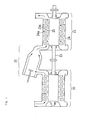
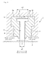
- Fig. 9 is a cross sectional view of one example of a prior art leaf seal (shaft seal mechanism) of the kind mentioned above, wherein this leaf seal is seen on a cross section including an axis of a rotating shaft.
- numeral 1 designates a leaf seal and numeral 2 a rotating shaft.
- the leaf seal 1 is constructed such that a plurality of thin plates 3 of a flat shape having a predetermined size of a plate width in an axial direction of the rotating shaft 2 are arranged in layers in which a minute gap is provided between each of the thin plates 3 in a circumferential direction of the rotating shaft 2 so that a thin plate assembly 9 of an annular shape is formed.
- These thin plates 3 have their outer circumferential proximal end side fixed to a split housing or leaf seal ring 5 (5a, 5b) via a brazed portion 4 and their inner circumferential distal end side arranged inclinedly with an acute angle relative to an outer circumferential surface of the rotating shaft 2 so as to make a slidable contact with the outer circumferential surface of the rotating shaft 2 by a pre-load.
- the leaf seal ring 5 is constructed by split seal rings 5a, 5b of a pair assembled together.
- each of the thin plates 3 when seen on a plan view thereof, has a T-shape in which the size of width w1 of the above-mentioned outer circumferential proximal end side is larger than the size of width w2 of the above-mentioned inner circumferential distal end side.
- the thin plates 3 seal the outer circumferential surface of the rotating shaft 2 and thereby an annular space formed around the rotating shaft 2 is divided into a higher pressure side area and a lower pressure side area.
- the leaf seal ring 5 comprises a higher pressure side side plate 7 on the side opposed to the higher pressure side area and a lower pressure side side plate 8 on the side opposed to the lower pressure side area so that the thin plates 3 are fitted in between the higher pressure side side plate 7 and the lower pressure side side plate 8.
- the respective side plates 7, 8 are arranged also to function as a guide plate for guiding a direction to which pressure acts.
- the leaf seal 1 constructed as mentioned above is inserted to be retained in a concave groove 10 of a T-shape formed in a stator side.
- a dynamic pressure effect is caused by the rotation of the rotating shaft 2 and the distal end of each of the thin plates 3 is levitated from the outer circumferential surface of the rotating shaft 2 so that contact of the distal ends of the thin plates 3 with the rotating shaft 2 is avoided. Thereby, abrasion of the thin plates 3 is avoided and the seal life is elongated.
- an optimized shape of the leaf seal ring 5 will be a T-shape in a cross section having the radial directional portion elongated and the outer circumferential portion formed larger than the inner circumferential portion so as to meet the shape of the thin plates 3.
- the concave groove to retain the leaf seal ring 5 is also needed to be made in such a shape as to have the radial directional portion deepened and the bottom portion (the outer circumferential portion) formed larger. But to work such shape of the concave groove in the stator is generally difficult and even if a compact shaft seal mechanism is developed, there might be a case where actual employment thereof is difficult.
- the shaft seal mechanism when seen on a cross section including an axis of the rotating shaft, has a shape having the radial directional portion elongated and the outer circumferential proximal end side formed larger than the inner circumferential distal end side, a structure into which this shaft seal mechanism can be easily assembled is desired. It is also desired to make the presently employed size of the thin plates 3 is made further smaller. But if the thin plates 3 are made smaller than the present size, then there is a possibility that a desired seal performance may not be stably obtained.
- the leaf seal 1 at the usual operation time receives a fluid force toward the lower pressure side area from the higher pressure side area, at the turbine start-up time, it receives a fluid force acting in the reverse direction of the fluid force direction in the usual operation time because the pressure in the turbine is reduced to vacuum.
- the leaf seal 1 receives the fluid force reversed from one direction to the other in the rotor axial direction and thereby the leaf seal 1 makes a slide motion along the rotor axial direction by the length of the fitting allowance relative to the stator side.
- the leaf seal 1 As the above-mentioned spring member is fixed to the stator side, if the leaf seal 1 makes the slide motion, the leaf seal 1 generates such a force as to bend the spring member in the rotor axial direction at the outer circumferential surface portion of the leaf seal 1.
- the spring member while receiving such a bending force to be inclinedly bent, may by some chance bite into the outer circumferential surface of the leaf seal 1 so that the normal activating function thereof cannot be exhibited. Then, an eccentric activating force is given onto the leaf seal 1 and this invites a possibility that the seal performance of the leaf seal 1 is badly influenced.
- a means by which no biting of the activating member is caused and a stable seal performance can be obtained is desired.
- EP 1298366 A2 discloses a shaft seal mechanism for a gas turbine which includes a plurality of thin plates that are arranged in an annular space between a rotor and a stator so as to form an annular thin plate assembly, and a plate spring that is disposed at an inner circumferential portion of a leaf seal retaining member and therefore biases an annular thin plate assembly in a radial outward direction, in order to prevent wear of the tips of the leaf seal when the rotor rotates at a low speed.
- the generic WO 92/05378 discloses a shaft seal mechanism that uses a brush seal member having a plurality of bristles, the free ends of which bear against a component against which the seal is to be effected.
- the bristles are disposed between a support plate on a high-pressure side and a support plate on a low-pressure side of the seal.
- the plate on the low-pressure side has a rubbing surface that extends to and is intended to contact the surface against which the seal is to be effected.
- a wave spring is located in a channel between a base of a housing that defines a channel in which the brush seal member is slidably received and the brush seal member to urge the latter outward and to be in a frictional contact.
- the present invention provides a shaft seal mechanism as defined by claim 1.
- Preferred embodiments are defined in the dependent claims.
- This shaft seal mechanism is constructed such that a plurality of thin plates are arranged in an annular space between a rotor and a stator so as to form an annular thin plate assembly, the thin plates have their outer circumferential proximal end side supported to the side of the stator and their inner circumferential distal end side non-fixed to an outer circumferential surface of the rotor so that the annular thin plate assembly divides the annular space between the rotor and the stator into a higher pressure side area and a lower pressure side area and an activating member is provided on the side of the annular thin plate assembly, the activating member supporting the annular thin plate assembly to be levitated coaxially with the rotor.
- the activating member is provided on the side of the annular thin plate assembly so as to support the annular thin plate assembly to be levitated coaxially with the rotor.
- the annular thin plate assembly When a start-up operation state is changed over to a continuous operation state, the annular thin plate assembly, when seen on a cross section including its center line, receives a force of which acting direction is reversed from one direction to the other along the center line and makes a slide motion along the center line.
- the activating member that levitates the annular thin plate assembly moves together with the annular thin plate assembly and no inclined contact nor biting of the thin plates with or to the surroundings of the annular thin plate assembly is caused.
- the center line of the shaft seal mechanism can be always correctly aligned with the axis of the rotor, there is caused no restriction by the biting of the activating member and a desired seal performance can be stably obtained.
- the activating member is constructed by a plate spring that is fixed to an outer circumferential portion of a leaf seal retaining member in which the annular thin plate assembly is retained.
- the activating member is the plate spring fixed to the outer circumferential portion of the leaf seal retaining member.
- this plate spring also makes the slide motion together with the annular thin plate assembly.
- the activating member is constructed by a bent plate spring that is fixed to an outer circumferential surface of a leaf seal retaining member in which the annular thin plate assembly is retained and the bent plate spring comprises a fixed end fixed to the outer circumferential surface of the leaf seal retaining member, a free end retained to the outer circumferential surface of the leaf seal retaining member so that a relative motion thereof in an axial direction of the rotor is regulated and a relative motion thereof around an axis of the rotor is allowed and an activating portion of a convex plate shape formed between the fixed end and the free end, the convex plate shape being swollen outward from the outer circumferential surface of the leaf seal retaining member.
- the activating member is the bent plate spring fixed to the outer circumferential surface of the leaf seal retaining member and this bent plate spring has the fixed end, the free end and the activating portion.
- this bent plate spring also makes the slide motion together with the annular thin plate assembly.
- the relative motion of the plate spring in the slide motion direction is regulated relative to the outer circumferential surface of the leaf seal retaining member, no inclined contact nor biting of the plate spring with or to this outer circumferential surface is caused.
- the activating force to levitate and support the annular thin plate assembly can be securely maintained.
- a large size fluid machine of the invention comprises a rotor and a stator to generate a power by converting a thermal energy of a high temperature high pressure working fluid into a mechanical rotational energy and further comprising a shaft seal mechanism to reduce a leakage of the working fluid along the rotor, in which the shaft seal mechanism is constructed in accordance with the invention.
- the same effect as the shaft seal mechanism of the invention can be obtained. Further, there is no obstruction by the biting of the activating member so that the seal performance can be maintained. Thereby, time and work required for the maintenance of the shaft seal mechanism can be reduced.
- the shaft seal mechanism while the slide motion of the shaft seal mechanism relative to the stator is allowed, the activating force to levitate and support the annular thin plate assembly can be securely maintained.
- Fig. 1 is a schematic constructional cross sectional view showing the embodiment of a gas turbine comprising a leaf seal (shaft seal mechanism) according to the present invention.
- numeral 20 designates a compressor, numeral 21 a combustor, numeral 22 a turbine and numeral 24 a stator.
- the compressor 20 takes thereinto a large quantity of air to be compressed.
- a portion of power obtained by a rotating shaft 23, as will be described below, is used as a drive force of the compressor.
- the combustor 21 functions to burn a mixture of fuel and the air compressed by the compressor 20.
- the turbine 22 introduces thereinto a combustion gas generated at the combustor 21 to be expanded so that the combustion gas so expanded is blown onto a plurality of rotor blades 23e fitted to the rotating shaft 23. Thereby, a thermal energy of the combustion gas is converted into a rotational energy so that a mechanical drive force is generated.
- a plurality of stator blades 24a are arranged on the stator 24 side, wherein the rotor blades 23e and the stator blades 24a are alternately provided in an axial direction of the rotating shaft 23.
- Each of the rotor blades 23e receives pressure of the combustion gas flowing in the axial direction of the rotating shaft 23 to thereby rotate the rotating shaft 23, so that the rotational energy given to the rotating shaft 23 is taken out from the shaft end to be effectively used.
- a leaf seal 25 is provided as a shaft seal mechanism for reducing leakage of the combustion gas leaking to a lower pressure side from a higher pressure side.
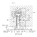
- Fig. 2 is an enlarged cross sectional view of the leaf seal 25, wherein the leaf seal 25, after assembled into the stator 24, is seen on a cross section including an axis of the rotating shaft 23.
- description will be made first on a basic construction and basic motion of the leaf seal 25 and then on a characteristic feature thereof.
- the leaf seal 25 is arranged to be positioned in an annular space between the rotating shaft 23 and the stator 24 and comprises a thin plate assembly 29A of an annular shape constructed by a plurality of thin plates 29 arranged in layers, wherein each of the thin plates 29 has its plate width direction arranged in parallel with the axial direction of the rotating shaft 23 and there is formed a minute gap between each of the thin plates 29 in a circumferential direction of the rotating shaft 23.
- Each of the thin plates 29 has its outer circumferential proximal end side supported to the stator 24 and its inner circumferential distal end side arranged inclinedly with an acute angle relative to an outer circumferential surface 23a of the rotating shaft 23 so as to make a slidable contact therewith.
- the annular thin plate assembly 29A comprising the thin plates 29 divides the annular space between the rotating shaft 23 and the stator 24 into a higher pressure side area and a lower pressure side area.
- each of the thin plates 29 has the T-shape in which the plate width changes when seen on its plane side
- the shape of the thin plate is not limited thereto and a rectangular shape having a constant plate width may be used instead. Even in this case, a T-shape is partially needed so as to be pinched between leaf seal retainers to be described below.
- the gas g leaking to the lower pressure side area from the higher pressure side area flows between an outer circumferential surface 23a of the rotating shaft 23 and a distal end of the thin plate 29 and also flows along the upper surface 29a and the lower surface 29b of the thin plate 29.
- the gas g flowing along the upper surface 29a and the lower surface 29b of the thin plate 29 flows in between the higher pressure side side plate 27 and the outer circumferential surface 23a of the rotating shaft 23 to flow radially toward the comer portion r2 from the comer portion r1 so that an area of lower pressure spreads to the outer circumferential proximal end side.
- a gas pressure distribution 30b, 30c of the gas pressure acting perpendicularly on the upper surface 29a and the lower surface 29b, respectively, of the thin plate 29 forms a triangular shape of distribution, as shown in Fig. 3(b) , in which the gas pressure becomes larger as it approaches to the inner circumferential distal end side and becomes smaller as it approaches to the outer circumferential proximal end side.
- the gas pressures of the upper surface 29a and the lower surface 29b at an arbitrary point P on a line elongating to the distal end side from the outer circumferential proximal end side of the thin plate 29 are compared with each other, there is caused a differential gas pressure between them.
- a gas pressure Fb acting on the lower surface 29b becomes higher than a gas pressure Fa acting on the upper surface 29a and this acts in the direction to deform the thin plate 29 so that the thin plate 29 is levitated from the rotating shaft 23.
- the thin plate 29 is deformed so as to levitate from the outer circumferential surface 23a and thereby a non-contact state of the thin plate 29 can be formed.
- the thin plate 29 receives an action of a dynamic pressure effect caused by the rotation of the rotating shaft 23 and thereby also the thin plate 29 levitates.
- each of the thin plates 29 is designed so as to have a rigidity in the axial direction of the rotating shaft 23 predetermined by the plate thickness. Also, as mentioned above, each of the thin plates 29 is supported to the stator 24 so as to have an acute angle relative to the outer circumferential surface 23a of the rotating shaft 23 in the rotational direction of the rotating shaft 23. Hence, while the rotating shaft 23 stops, the inner circumferential distal end of the thin plate 29 makes contact with the rotating shaft 23 by a pre-load, but while the rotating shaft 23 rotates, the dynamic pressure effect is generated and thereby the inner circumferential distal end of the thin plate 29 is levitated and the non-contact state between the thin plate 29 and the rotating shaft 23 is realized.
- the leaf seal 25 of the present embodiment is constructed comprising the plurality of thin plates 29 arranged in layers in which each of the thin plates 29 is a plate approximately of T-shape having a plate width of the above-mentioned outer circumferential proximal end side formed larger than a plate width of the above-mentioned inner circumferential distal end side and also comprising two leaf seal retainers 51, 52 (thin plate retaining rings) of a pair that retain and support the thin plates 29 in an annular state, a higher pressure side plate 53 of an annular shape fitted in between one side edge, opposed to the higher pressure side area, of each of the thin plates 29 and one of the leaf seal retainers 51 so as to abut on this one side edge, a lower pressure side plate 54 (a gap forming member) of an annular shape fitted in between the other side edge, opposed to the lower pressure side area, of each of the thin plates 29 and the other of the leaf seal retainers 52 so as to abut on this other side edge,
- Each of the thin plates 29 is a thin steel plate, having a flexibility, approximately of T-shape and has its both side edges formed with cut-off portions 29a.
- These thin plates 29 have their outer circumferential proximal end sides fixed to each other by welding (welded places will be described below with reference to Fig. 7 ) so as to form the thin plate assembly 29A having a flexibility as a whole.
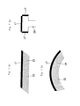
- the higher pressure side plate 53 is an annular thin plate and, when seen on the cross section including the axis of the rotating shaft 23, has one side surface of its outer circumferential side portion formed with a stepped portion of which thickness is larger than a thickness of the inner circumferential side portion thereof.
- the lower pressure side plate 54 is an annular thin plate and, when seen on the above-mentioned cross section, has one side surface of its outer circumferential side portion formed with a stepped portion of which thickness is larger than a thickness of the inner circumferential side portion thereof.
- These higher pressure side plate 53 and lower pressure side plate 54 have their respective stepped portions made engageable with the above-mentioned cut-off portions 29a of the thin plates 29 so as to make a close contact with both side surfaces of the thin plates 29 and then the so assembled members are pinched to be retained between the two leaf seal retainers 51, 52.
- the lower pressure side plate 54 when seen on the cross section including the axis of the rotating shaft, has its length size formed smaller than the higher pressure side plate 53.
- Each of the leaf seal retainers 51, 52 is a metal member having a flexibility and, when seen on the cross section including the axis of the rotating shaft 23, has an approximate C-shape.
- the leaf seal retainers 51, 52 when jointed together, form concave portions 51a, 52a therein and the portion of which width is enlarged of each of the thin plates 29 and the spacer 55 are fitted in the concave portions 51a, 52a.
- concave portions 51b, 52b are formed so that the plate springs 56 are fitted therein.
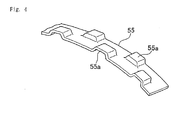
- the spacer 55 is a plate spring, formed with a plurality of convex portions 55a, that, when pressed, elastically deforms to thereby generate an activating force.
- the activating force of the spacer 55 urges the annular thin plate assembly 29A on its outer circumferential side against the concave portions 51a, 52a.
- the spacer 55 at its upper surface and each of the leaf seal retainers 51, 52 are jointed together by welding as shown by welded places y4 and the relative position of these members is fixed.
- each of the plate springs 56 is arranged on and along an outer circumferential surface of the leaf seal retainers 51, 52 in the concave portion 51b, 52b.
- the plate spring 56 has its one end fixed to the outer circumferential surface of the leaf seal retainers 51, 52 as a fixed end 56a and the other end retained free as a free end 56b of which motion in the axial direction of the rotating shaft 23 relative to the outer circumferential surface of the leaf seal retainers 51, 52 is regulated and of which motion around the axis of the rotating shaft 23 relative to the outer circumferential surface of the leaf seal retainers 51, 52 is allowed.
- the plate spring 56 has its central portion between the fixed end 56a and the free end 56b swollen outwardly from the outer circumferential surface of the leaf seal retainers 51, 52 as an activating portion 56c of a convex plate shape. That is, the fixed end 56a, while it is fitted in the concave portion 51 b, 52b, is pressed down from above by a fixing member 56e to be fixed non-movably relative to the outer circumferential surface of the leaf seal retainers 51, 52.
- the free end 56b while it is fitted in the concave groove 51b, 52b, is pressed down from above by a guide member 56d to be retained so that the relative movement thereof in the axial direction of the rotating shaft 23 is regulated and, at the same time, the relative movement thereof around the axis of the rotating shaft 23 is allowed.
- the construction is made such that the plate spring 56 is integrated with the annular thin plate assembly 29A via the leaf seal retainers 51, 52.
- the leaf seal 25, constructed as mentioned above, together with a fitting piece (fitting member) 61 is fitted in a concave groove 71 formed in the stator 24 side.
- the concave groove 71 when seen on the cross section of Fig. 2 , has a minimum size of the groove width w4 that is larger than a minimum size of a plate width w3 of the thin plate 29.
- a first slidable contact surface 71a with which an inner circumferential surface of the leaf seal retainer 51 makes a slidable contact
- a second slidable contact surface 71b opposed to the first slidable contact surface 71a, with which an outer circumferential surface of the plate spring 56 makes a slidable contact.
- the concave groove 71 is worked on the premise that a space formed at the time when the leaf seal 25 is fitted in the stator 24 is filled by the fitting piece 61, when the concave groove 71 is formed in the stator 24 side, the work is done such that a minimum size of a groove width w4 of the concave groove 71 becomes larger than the size of thickness of the leaf seal 25.
- the width of the concave groove 71 is made larger.
- the fitting piece 61 In the state that the thin plates 29 are assembled into the concave groove 71 via the leaf seal retainers 51, 52 (that is, in the state that the leaf seal 25 is fitted in), the fitting piece 61, when seen on the cross section of Fig. 2 , is an annular member to be fitted in a space formed between the concave groove 71 and one side surface (that is, one side surface on the side of the lower pressure side area) of the fitting piece 61. On this side surface of the fitting piece 61, there are formed a third slidable contact surface 61a with which the inner circumferential surface of the leaf seal retainer 52 makes a slidable contact and a pressure receiving surface 61b on which the lower pressure side plate 54 abuts.
- an outer circumferential side portion thereof (that is, the leaf seal retainers 51, 52 between which the outer circumferential proximal end side of the thin plates 29 is pinched) is arranged movably in the axial direction of the rotating shaft 23 relative to the concave groove 71.
- the size of a gap formed between a side edge opposed to the lower pressure side area of each of the thin plates 29 and the pressure receiving surface 61b is set to the same size as a thickness t of the lower pressure side plate 54 to be fitted in between them.
- the gap size as designed can be obtained with a high reproducibility.
- the fitting piece 61 when seen on the cross section of Fig. 2 , is arranged downstream of the annular thin plate assembly 29A (that is, on the side of the lower pressure side area relative to the leaf seal 25) and moreover, on an inner circumferential surface of the fitting piece 61, a labyrinth seal 61d as another seal mechanism is integrally formed so that this labyrinth seal 61 together with the annular thin plate assembly 29A divides the annular space between the stator 24 and the rotating shaft 23 into the higher pressure side area and the lower pressure side area.
- the labyrinth seal 61d and the annular thin plate assembly 29A constitute a multiple seal structure and thereby a leakage of the working fluid to the lower pressure side area from the higher pressure side area can be further reduced.
- the present embodiment is described with respect to the example where the fitting piece 61 and the labyrinth seal 61d are integrally provided, the present invention is not limited thereto. That is, the original function of the fitting piece 61 aims to facilitate the work of the concave groove 71 and it is not necessarily intended to show that the labyrinth seal 61d is essential.
- a manufacturing process of the leaf seal 25 constructed as mentioned above and an assembling thereof into the stator 24 will be described next with reference to Figs. 7 and 8 .
- a thin plate welding process, bending process, ring fitting process, plate spring fitting process, fitting piece inserting process and shaft seal member inserting process are carried out.
- each of the thin plates 29, made in the T-shape by punching of a steel plate is lapped inclinedly one on another so as to form layers and then the mentioned outer circumferential proximal end side of the layers is welded. That is, as shown in Fig. 7(b) , each of the thin plates 29 has an outer circumferential end and both side ends of its outer circumferential proximal end side welded so that the thin plates 29 are jointed together, as shown by welded places y1 to y3.
- Fig. 7(c) shows the state of the thin plates 29 after the bending process.
- the annular higher pressure side plate 53 is first pinched to be retained between the one side edge, opposed to the higher pressure side area, of each of the thin plates 29 and the one leaf seal retainer 51 so as to abut on this one side edge.
- the annular lower pressure side plate 54 is pinched to be retained between the other side edge, opposed to the lower pressure side area, of each of the thin plates 29 and the other leaf seal retainer 52 so as to abut on this other side edge.
- the spacer 55 for regulating the motion of each of the thin plates 29 relative to the leaf seal retainers 51, 52 is fitted in to be retained between the outer circumferential proximal end side of the thin plates 29 and the leaf seal retainers 51, 52.
- the leaf seal retainers 51, 52 so assembled together with the other members are welded to be fixed to the spacer 55 at the welded places y4 ( Fig. 2 ).
- the plate spring 56 is fitted in along the concave portion 51b, 52b and then the fixed end 56a thereof is fixed by the fixing member 56e and the free end 56b thereof is pressed to be fitted by the guide member 56d. While the free end 56b side is regulated to move in the axial direction of the rotating shaft 23, it is allowed to move in the circumferential direction of the rotating shaft 23.
- the plate spring 56 receives a compression so that the convex plate shape of the activating portion 56c is depressed, the plate spring 56 can elongate along its lengthwise direction (that is, along the outer circumferential surfaces of the leaf seal retainers 51, 52). It is to be noted that fixing of the fixed end 56a may also be directly carried out by welding without using the fixing member 56e.
- the fitting piece 61 is inserted to be fitted along a curvature of the concave groove 71. At this time, care must be taken so that no gap is generated between the side surface on the side of the lower pressure side area of the fitting piece 61 and the concave groove 71.
- the assembled shaft seal member (the leaf seal 25), while it is bent along the curvature of the concave groove 71, is inserted into the concave groove 71. It is to be noted that the shaft seal member inserting process and the fitting piece inserting process may be carried out at the same time.
- the curvature of the leaf seal 25 can be freely changed according to the place where the leaf seal 25 is to be provided. Hence, such an exclusive jig as in the prior art case is not needed to be individually prepared and thereby the manufacturing cost can be reduced.
- a fluid force F acts on the annular thin plate assembly 29A toward the lower pressure side area from the higher pressure side area in operation.
- the entire leaf seal 25 is moved toward the lower pressure side area from the higher pressure side area by the fluid force F received by the thin plates 29, the side edges of the thin plates 29 on the side of the lower pressure side area abut on the pressure receiving surface 61b via the lower pressure side plate 54 to stop there.
- the gap size formed between the side edges of the thin plates 29 and the pressure receiving surface 61b is ensured to be the same as the thickness size t of the lower pressure side plate 54.
- annular thin plate assembly 29A as seen on a cross section including a center line of this annular member, when a start-up operation state is changed over to a continuous operation state, the force acting direction is reversed from one direction to the other direction along the direction of this center line and hence a slide motion of the annular thin plate assembly 29A is caused along the direction of the center line. Nevertheless, the plate spring 56 to levitate the annular thin plate assembly 29A moves together with the annular thin plate assembly 29A and thus no inclined slidable contact nor biting of the thin plates 29 is caused.
- the concave groove 71 having its width formed larger than the minimum size of the plate width w3 of the thin plates 29 and the fitting piece 61 fitted in the gap formed between the concave groove 71 and the thin plates 29 in the state that the thin plates 29 are assembled in the concave groove 71.
- the concave groove 71 can be worked so as to have a wider width that is easily workable and thereby the leaf seal 25 having its radial directional portion elongated and its outer circumferential proximal end side formed larger than its inner circumferential distal end side can be easily assembled into the stator 24 side.
- the leaf seal 25 having its radial directional portion elongated and its outer circumferential proximal end side formed larger than its inner circumferential distal end side can be easily assembled into the stator 24 side. Thereby, it becomes possible to employ a leaf seal made smaller and to make an entire device using this leaf seal compact.
- the fitting piece 61 is arranged downstream of the leaf seal 25 and there is provided the labyrinth seal 61d.
- the labyrinth seal 61d together with the annular thin plate assembly 29A constitutes a multiple seal structure and thereby a leakage of the working fluid to the lower pressure side area from the higher pressure side area can be further reduced.
- the plate springs 56 are integrally fixed to the outer circumferential surface of the leaf seal 25.
- the plate springs 56 are prevented from making an inclined slidable contact with the outer circumferential surface portion of the leaf seal retainers 51, 52 or from biting therein and thereby the center line of the leaf seal 25 can be always correctly aligned with the axis of the rotating shaft 23.
- the entire leaf seal 25 is made movable relative to the interior of the concave groove 71 and, in the concave groove 71 on the stator 24 side, there are provided the pressure receiving surface provided via the fitting piece 61 and the lower pressure side plate 54 pinched between the side edges of the thin plates 29 and the pressure receiving surface 61b so as to form a predetermined gap size therebetween.
- the gap size formed between the thin plates 29 and the pressure receiving surface 61 on the lower pressure side can be accurately controlled as designed. Hence, a desired seal performance can be stably obtained.
- the gap size can be easily adjusted as compared with the prior art case.
- such a method is employed as to compare the thin plate welding process, bending process, ring fitting process, plate spring fitting process, fitting piece inserting process and shaft seal member inserting process.
- the curvature of the leaf seal 25 can be freely changed according to the place where the leaf seal 25 is to be provided and hence such an exclusive jig as in the prior art case is not needed to be individually prepared. Thereby, the manufacturing cost of the leaf seal 25 can be reduced.
Claims (3)
- Mécanisme de joint pour arbre comprenant
une pluralité de plaques minces (29) qui sont disposées dans un espace annulaire entre un rotor (23) et un stator (24) de sorte à former un ensemble de plaques minces annulaire (29A), lesdites plaques minces (29) ont leur côté d'extrémité proximale circonférentiel externe supporté sur le côté dudit stator (24) et leur côté d'extrémité distale circonférentiel interne non fixé à une surface circonférentielle externe (23a) dudit rotor (23) afin que ledit ensemble de plaques minces annulaire (29A) sépare ledit espace annulaire entre ledit rotor (23) et ledit stator (24) en une zone côté pression supérieure et une zone côté pression inférieure, et
un élément d'activation comprenant un ressort à lame (56) qui est prévu sur le côté dudit ensemble de plaques minces annulaire (29A), ledit élément d'activation permettant audit ensemble de plaques minces annulaire (29A) d'être en lévitation coaxialement avec ledit rotor (23),
dans lequel ledit ressort à lame (56) est fixé à une partie circonférentielle externe d'un élément de retenue de joint à lamelles (51, 52) dans lequel ledit ensemble de plaques minces annulaire (29A) est retenu, et caractérisé en ce que ledit ressort à lame est un ressort à lame pliée (56) qui est fixé à une surface circonférentielle externe de l'élément de retenue de joint à lamelles (51, 52) et ledit ressort à lame pliée (56) comprend une extrémité fixée (56a) fixée à la surface circonférentielle externe dudit élément de retenue de joint à lamelles (51, 52), une extrémité libre (56b) retenue à la surface circonférentielle externe dudit élément de retenue de joint à lamelles (51, 52) de sorte qu'un mouvement relatif de celui-ci dans une direction axiale dudit rotor (23) soit régulé et un mouvement relatif de celui-ci autour d'un axe dudit rotor (23) soit permis, et une partie d'activation (56c) d'une forme de plaque convexe formée entre ladite extrémité fixée (56a) et ladite extrémité libre (56b), ladite forme de plaque convexe étant gonflée vers l'extérieur depuis la surface circonférentielle externe dudit élément de retenue de joint à lamelles (51, 52). - Mécanisme de joint pour arbre selon la revendication 1, caractérisé en ce que lesdites extrémités fixées et libres (56a, 56b) dudit ressort à lame pliée (56) sont respectivement insérées dans une partie concave (51, 52a, 51b, 52b) formée dans la surface circonférentielle externe dudit élément de retenue de joint à lamelles (51, 52).
- Machine à fluide de grande taille, caractérisée en ce qu'elle comprend un rotor (23) et un stator (24) pour générer une puissance en convertissant une énergie thermique d'un fluide de travail à haute pression et haute température en une énergie de rotation mécanique et comprenant en outre un mécanisme de joint pour arbre selon la revendication 1 ou 2 pour réduire une fuite du fluide de travail le long dudit rotor (23).
Applications Claiming Priority (2)
| Application Number | Priority Date | Filing Date | Title |
|---|---|---|---|
| JP2003143271 | 2003-05-21 | ||
| EP04011773A EP1479951B1 (fr) | 2003-05-21 | 2004-05-18 | Garniture étanche de l'arbre |
Related Parent Applications (1)
| Application Number | Title | Priority Date | Filing Date |
|---|---|---|---|
| EP04011773.1 Division | 2004-05-18 |
Publications (3)
| Publication Number | Publication Date |
|---|---|
| EP2397728A2 EP2397728A2 (fr) | 2011-12-21 |
| EP2397728A3 EP2397728A3 (fr) | 2012-04-18 |
| EP2397728B1 true EP2397728B1 (fr) | 2013-11-13 |
Family
ID=33095435
Family Applications (3)
| Application Number | Title | Priority Date | Filing Date |
|---|---|---|---|
| EP11179662.9A Active EP2397729B1 (fr) | 2003-05-21 | 2004-05-18 | Structure d'assemblage de mécanisme de joint pour arbre et machine pour fluide de grande taille |
| EP04011773A Active EP1479951B1 (fr) | 2003-05-21 | 2004-05-18 | Garniture étanche de l'arbre |
| EP11179659.5A Active EP2397728B1 (fr) | 2003-05-21 | 2004-05-18 | Mécanisme de joint pour arbre et machine pour fluide de grande taille |
Family Applications Before (2)
| Application Number | Title | Priority Date | Filing Date |
|---|---|---|---|
| EP11179662.9A Active EP2397729B1 (fr) | 2003-05-21 | 2004-05-18 | Structure d'assemblage de mécanisme de joint pour arbre et machine pour fluide de grande taille |
| EP04011773A Active EP1479951B1 (fr) | 2003-05-21 | 2004-05-18 | Garniture étanche de l'arbre |
Country Status (3)
| Country | Link |
|---|---|
| US (1) | US7226053B2 (fr) |
| EP (3) | EP2397729B1 (fr) |
| CN (1) | CN100396885C (fr) |
Families Citing this family (36)
| Publication number | Priority date | Publication date | Assignee | Title |
|---|---|---|---|---|
| GB0417613D0 (en) * | 2004-08-07 | 2004-09-08 | Rolls Royce Plc | A leaf seal arrangement |
| JP3917993B2 (ja) * | 2004-08-10 | 2007-05-23 | 三菱重工業株式会社 | 軸シール機構及び軸シール機構をステータに取り付ける構造並びにこれらを備えたタービン。 |
| JP3970298B2 (ja) * | 2005-11-10 | 2007-09-05 | 三菱重工業株式会社 | 軸シール機構 |
| US7641200B2 (en) * | 2005-11-28 | 2010-01-05 | General Electric Company | Variable clearance packing ring arrangement |
| US7419164B2 (en) * | 2006-08-15 | 2008-09-02 | General Electric Company | Compliant plate seals for turbomachinery |
| US8382119B2 (en) * | 2006-08-15 | 2013-02-26 | General Electric Company | Compliant plate seals for turbomachinery |
| US20080169614A1 (en) * | 2007-01-12 | 2008-07-17 | Shorya Awtar | Compliant plate seal assembly apparatus and assembly method thereof |
| US7909335B2 (en) * | 2008-02-04 | 2011-03-22 | General Electric Company | Retractable compliant plate seals |
| US20100143102A1 (en) * | 2008-02-18 | 2010-06-10 | General Electric Company | Compliant plate seal with self-correcting behavior |
| JP4898743B2 (ja) | 2008-06-09 | 2012-03-21 | 三菱重工業株式会社 | 回転機械のシール構造 |
| DE102009015122A1 (de) * | 2009-03-31 | 2010-10-14 | Alstom Technology Ltd. | Lamellendichtung für eine Strömungsmaschine |
| WO2010146805A1 (fr) * | 2009-06-16 | 2010-12-23 | 三菱重工業株式会社 | Joint d'arbre et machine rotative pourvue de ce dernier |
| GB0922074D0 (en) | 2009-12-18 | 2010-02-03 | Rolls Royce Plc | A leaf seal assembly |
| JP5473685B2 (ja) * | 2010-03-10 | 2014-04-16 | 三菱重工業株式会社 | 軸シール装置及び軸シール装置を備える回転機械 |
| JP5631155B2 (ja) * | 2010-10-27 | 2014-11-26 | 三菱重工業株式会社 | 軸シール機構及びこれを備える回転機械 |
| US8454023B2 (en) * | 2011-05-10 | 2013-06-04 | General Electric Company | Retractable seal system |
| US9103224B2 (en) | 2011-12-29 | 2015-08-11 | General Electric Company | Compliant plate seal for use with rotating machines and methods of assembling a rotating machine |
| JP5851890B2 (ja) | 2012-03-08 | 2016-02-03 | 三菱重工業株式会社 | 軸シール装置 |
| US9540942B2 (en) * | 2012-04-13 | 2017-01-10 | General Electric Company | Shaft sealing system for steam turbines |
| US9115810B2 (en) * | 2012-10-31 | 2015-08-25 | General Electric Company | Pressure actuated film riding seals for turbo machinery |
| US9045994B2 (en) * | 2012-10-31 | 2015-06-02 | General Electric Company | Film riding aerodynamic seals for rotary machines |
| CN102966589B (zh) * | 2012-11-02 | 2015-04-15 | 三一能源重工有限公司 | 一种迷宫式密封结构及安装方法 |
| US20140154060A1 (en) * | 2012-12-05 | 2014-06-05 | General Electric Company | Turbomachine seal assembly and method of sealing a rotor region of a turbomachine |
| JP6012505B2 (ja) * | 2013-02-22 | 2016-10-25 | 三菱重工業株式会社 | 軸シール装置及び回転機械 |
| CN103244682B (zh) * | 2013-04-24 | 2016-01-27 | 南京博沃科技发展有限公司 | 叶片式密封装置 |
| JP6125412B2 (ja) * | 2013-11-22 | 2017-05-10 | 三菱重工業株式会社 | 軸シール装置、回転機械、及び軸シール装置の製造方法 |
| CN103982248B (zh) * | 2014-05-21 | 2016-04-06 | 南京博沃科技发展有限公司 | 具有间隙控制功能的叶片式密封装置 |
| US10161259B2 (en) | 2014-10-28 | 2018-12-25 | General Electric Company | Flexible film-riding seal |
| JP6276209B2 (ja) | 2015-02-20 | 2018-02-07 | 三菱日立パワーシステムズ株式会社 | タービン用シール装置及びタービン、並びにシール装置用の薄板 |
| JP6358976B2 (ja) * | 2015-02-20 | 2018-07-18 | 三菱日立パワーシステムズ株式会社 | タービン用シール装置及びタービン、並びにシール装置用の薄板 |
| CN108708974B (zh) * | 2015-12-21 | 2020-06-30 | 海信容声(广东)冰箱有限公司 | 一种密封垫圈、冰箱内置饮水机及冰箱 |
| CN105673854B (zh) * | 2016-01-18 | 2017-07-11 | 沈阳航空航天大学 | 一种中间引气提供自同心平衡力的密封装置 |
| JP6601677B2 (ja) * | 2016-02-16 | 2019-11-06 | 三菱日立パワーシステムズ株式会社 | シール装置及び回転機械 |
| JP6675262B2 (ja) * | 2016-05-09 | 2020-04-01 | 三菱日立パワーシステムズ株式会社 | シールセグメント及び回転機械 |
| JP6631837B2 (ja) * | 2016-05-09 | 2020-01-15 | 三菱日立パワーシステムズ株式会社 | シールセグメント及び回転機械 |
| US11085315B2 (en) * | 2019-07-09 | 2021-08-10 | General Electric Company | Turbine engine with a seal |
Family Cites Families (28)
| Publication number | Priority date | Publication date | Assignee | Title |
|---|---|---|---|---|
| US4202554A (en) * | 1978-05-17 | 1980-05-13 | Rolls-Royce Limited | Brush seals |
| JPH0660692B2 (ja) * | 1986-02-27 | 1994-08-10 | 三菱重工業株式会社 | 回転機械のシ−ル装置 |
| CN86101455B (zh) * | 1986-03-03 | 1988-03-23 | 三菱重工业株式会社 | 回转流体机械的密封装置 |
| GB8907695D0 (en) * | 1989-04-05 | 1989-05-17 | Cross Mfg Co | Seals |
| FR2650048B1 (fr) * | 1989-07-21 | 1992-05-07 | Alsthom Gec | Garniture d'etancheite pour arbre rotatif |
| GB9020317D0 (en) * | 1990-09-18 | 1990-10-31 | Cross Mfg Co | Sealing devices |
| GB9103459D0 (en) * | 1991-02-19 | 1991-04-03 | Cross Mfg Co | Brush seal assembly |
| GB9801864D0 (en) * | 1998-01-30 | 1998-03-25 | Rolls Royce Plc | A seal arrangement |
| US6045134A (en) * | 1998-02-04 | 2000-04-04 | General Electric Co. | Combined labyrinth and brush seals for rotary machines |
| US6250640B1 (en) * | 1998-08-17 | 2001-06-26 | General Electric Co. | Brush seals for steam turbine applications |
| JP3358993B2 (ja) | 1998-09-21 | 2002-12-24 | 三菱重工業株式会社 | ターボ回転機械の自動調整シール |
| US6139019A (en) * | 1999-03-24 | 2000-10-31 | General Electric Company | Seal assembly and rotary machine containing such seal |
| US6308958B1 (en) * | 1999-10-12 | 2001-10-30 | General Electric Company | Arrangement and method for radially positioning a turbine brush seal |
| US6331006B1 (en) * | 2000-01-25 | 2001-12-18 | General Electric Company | Brush seal mounting in supporting groove using flat spring with bifurcated end |
| DE10006298A1 (de) * | 2000-02-12 | 2001-08-16 | Abb Patent Gmbh | Dichtung für umlaufende Teile |
| US6540231B1 (en) * | 2000-02-29 | 2003-04-01 | General Electric Company | Surface following brush seal |
| US6609888B1 (en) * | 2000-04-24 | 2003-08-26 | Watson Cogeneration Company | Method and apparatus for reducing contamination in an axial compressor |
| JP3616016B2 (ja) | 2000-04-28 | 2005-02-02 | 三菱重工業株式会社 | 軸シール機構及びガスタービン |
| CA2359933C (fr) * | 2001-02-08 | 2006-03-14 | Mitsubishi Heavy Industries, Ltd. | Joint pour arbre tournant, et turbine a gaz |
| JP2002257242A (ja) * | 2001-02-27 | 2002-09-11 | Mitsubishi Heavy Ind Ltd | 回転機械の軸シール |
| US6550777B2 (en) * | 2001-06-19 | 2003-04-22 | General Electric Company | Split packing ring segment for a brush seal insert in a rotary machine |
| JP4824225B2 (ja) * | 2001-08-29 | 2011-11-30 | イーグル工業株式会社 | 板ブラシシール装置 |
| JP3702212B2 (ja) * | 2001-09-28 | 2005-10-05 | 三菱重工業株式会社 | 軸シール機構及びタービン |
| JP3593082B2 (ja) * | 2001-10-09 | 2004-11-24 | 三菱重工業株式会社 | 軸シール機構及びタービン |
| US6840519B2 (en) * | 2001-10-30 | 2005-01-11 | General Electric Company | Actuating mechanism for a turbine and method of retrofitting |
| US6644668B1 (en) * | 2002-06-13 | 2003-11-11 | General Electric Company | Brush seal support |
| US6991235B2 (en) * | 2003-11-07 | 2006-01-31 | The Boeing Company | Gas-buffered seal assembly and method therefor |
| JP3917993B2 (ja) * | 2004-08-10 | 2007-05-23 | 三菱重工業株式会社 | 軸シール機構及び軸シール機構をステータに取り付ける構造並びにこれらを備えたタービン。 |
-
2004
- 2004-04-21 CN CNB2004100369402A patent/CN100396885C/zh not_active Expired - Lifetime
- 2004-05-18 EP EP11179662.9A patent/EP2397729B1/fr active Active
- 2004-05-18 EP EP04011773A patent/EP1479951B1/fr active Active
- 2004-05-18 EP EP11179659.5A patent/EP2397728B1/fr active Active
- 2004-05-19 US US10/848,315 patent/US7226053B2/en active Active
Also Published As
| Publication number | Publication date |
|---|---|
| EP1479951A2 (fr) | 2004-11-24 |
| EP1479951B1 (fr) | 2013-04-03 |
| EP2397728A2 (fr) | 2011-12-21 |
| CN100396885C (zh) | 2008-06-25 |
| US7226053B2 (en) | 2007-06-05 |
| EP2397729A2 (fr) | 2011-12-21 |
| CN1573024A (zh) | 2005-02-02 |
| EP1479951A3 (fr) | 2011-11-16 |
| EP2397729B1 (fr) | 2013-10-23 |
| EP2397728A3 (fr) | 2012-04-18 |
| EP2397729A3 (fr) | 2012-04-18 |
| US20050012275A1 (en) | 2005-01-20 |
Similar Documents
| Publication | Publication Date | Title |
|---|---|---|
| EP2397728B1 (fr) | Mécanisme de joint pour arbre et machine pour fluide de grande taille | |
| EP1479952B1 (fr) | Dispositif d'étanchéité pour axe | |
| US7735833B2 (en) | Double padded finger seal | |
| JP3917993B2 (ja) | 軸シール機構及び軸シール機構をステータに取り付ける構造並びにこれらを備えたタービン。 | |
| US8025296B2 (en) | Shaft sealing mechanism | |
| US9115810B2 (en) | Pressure actuated film riding seals for turbo machinery | |
| US7425003B2 (en) | Over center high deflection pressure energizing low leakage seal | |
| US20040150165A1 (en) | Seal assembly and rotary machine containing such seal | |
| WO2010146805A1 (fr) | Joint d'arbre et machine rotative pourvue de ce dernier | |
| JP3872800B2 (ja) | 軸シール機構、軸シール機構の組み付け構造、及び大型流体機械 | |
| EP1165979B1 (fr) | Palier hybride | |
| CN108350934B (zh) | 箔片轴承及其制造方法、以及箔片轴承的中间制造体 | |
| JP3950455B2 (ja) | 軸シール用部材及び軸シール機構及び大型流体機械 | |
| JP4643228B2 (ja) | 軸シール | |
| JP3917997B2 (ja) | 軸シール機構 | |
| JP3986520B2 (ja) | 軸シール機構 | |
| JP3944206B2 (ja) | 軸シール機構 | |
| JP2007263376A (ja) | 軸シール機構 | |
| JPS6116209A (ja) | ラビリンスシ−ル装置 | |
| JP4264384B2 (ja) | 軸シール機構 | |
| JP2009127775A (ja) | 回転機械のシール装置および回転機械 | |
| JP2023046778A (ja) | フォイル軸受 | |
| JP2005009684A (ja) | 軸シール機構 |
Legal Events
| Date | Code | Title | Description |
|---|---|---|---|
| 17P | Request for examination filed |
Effective date: 20110831 |
|
| AC | Divisional application: reference to earlier application |
Ref document number: 1479951 Country of ref document: EP Kind code of ref document: P |
|
| AK | Designated contracting states |
Kind code of ref document: A2 Designated state(s): AT BE BG CH CY CZ DE DK EE ES FI FR GB GR HU IE IT LI LU MC NL PL PT RO SE SI SK TR |
|
| AX | Request for extension of the european patent |
Extension state: AL HR LT LV MK |
|
| PUAI | Public reference made under article 153(3) epc to a published international application that has entered the european phase |
Free format text: ORIGINAL CODE: 0009012 |
|
| PUAL | Search report despatched |
Free format text: ORIGINAL CODE: 0009013 |
|
| AK | Designated contracting states |
Kind code of ref document: A3 Designated state(s): AT BE BG CH CY CZ DE DK EE ES FI FR GB GR HU IE IT LI LU MC NL PL PT RO SE SI SK TR |
|
| AX | Request for extension of the european patent |
Extension state: AL HR LT LV MK |
|
| RIC1 | Information provided on ipc code assigned before grant |
Ipc: F16J 15/32 20060101AFI20120315BHEP |
|
| 17Q | First examination report despatched |
Effective date: 20121114 |
|
| GRAP | Despatch of communication of intention to grant a patent |
Free format text: ORIGINAL CODE: EPIDOSNIGR1 |
|
| INTG | Intention to grant announced |
Effective date: 20130606 |
|
| GRAS | Grant fee paid |
Free format text: ORIGINAL CODE: EPIDOSNIGR3 |
|
| GRAA | (expected) grant |
Free format text: ORIGINAL CODE: 0009210 |
|
| AC | Divisional application: reference to earlier application |
Ref document number: 1479951 Country of ref document: EP Kind code of ref document: P |
|
| AK | Designated contracting states |
Kind code of ref document: B1 Designated state(s): AT BE BG CH CY CZ DE DK EE ES FI FR GB GR HU IE IT LI LU MC NL PL PT RO SE SI SK TR |
|
| REG | Reference to a national code |
Ref country code: GB Ref legal event code: FG4D |
|
| REG | Reference to a national code |
Ref country code: CH Ref legal event code: EP |
|
| REG | Reference to a national code |
Ref country code: AT Ref legal event code: REF Ref document number: 640718 Country of ref document: AT Kind code of ref document: T Effective date: 20131215 |
|
| REG | Reference to a national code |
Ref country code: IE Ref legal event code: FG4D |
|
| REG | Reference to a national code |
Ref country code: DE Ref legal event code: R096 Ref document number: 602004043806 Country of ref document: DE Effective date: 20140109 |
|
| REG | Reference to a national code |
Ref country code: NL Ref legal event code: VDEP Effective date: 20131113 |
|
| REG | Reference to a national code |
Ref country code: AT Ref legal event code: MK05 Ref document number: 640718 Country of ref document: AT Kind code of ref document: T Effective date: 20131113 |
|
| PG25 | Lapsed in a contracting state [announced via postgrant information from national office to epo] |
Ref country code: NL Free format text: LAPSE BECAUSE OF FAILURE TO SUBMIT A TRANSLATION OF THE DESCRIPTION OR TO PAY THE FEE WITHIN THE PRESCRIBED TIME-LIMIT Effective date: 20131113 Ref country code: FI Free format text: LAPSE BECAUSE OF FAILURE TO SUBMIT A TRANSLATION OF THE DESCRIPTION OR TO PAY THE FEE WITHIN THE PRESCRIBED TIME-LIMIT Effective date: 20131113 Ref country code: SE Free format text: LAPSE BECAUSE OF FAILURE TO SUBMIT A TRANSLATION OF THE DESCRIPTION OR TO PAY THE FEE WITHIN THE PRESCRIBED TIME-LIMIT Effective date: 20131113 |
|
| PG25 | Lapsed in a contracting state [announced via postgrant information from national office to epo] |
Ref country code: ES Free format text: LAPSE BECAUSE OF FAILURE TO SUBMIT A TRANSLATION OF THE DESCRIPTION OR TO PAY THE FEE WITHIN THE PRESCRIBED TIME-LIMIT Effective date: 20131113 Ref country code: AT Free format text: LAPSE BECAUSE OF FAILURE TO SUBMIT A TRANSLATION OF THE DESCRIPTION OR TO PAY THE FEE WITHIN THE PRESCRIBED TIME-LIMIT Effective date: 20131113 Ref country code: BE Free format text: LAPSE BECAUSE OF FAILURE TO SUBMIT A TRANSLATION OF THE DESCRIPTION OR TO PAY THE FEE WITHIN THE PRESCRIBED TIME-LIMIT Effective date: 20131113 Ref country code: CY Free format text: LAPSE BECAUSE OF FAILURE TO SUBMIT A TRANSLATION OF THE DESCRIPTION OR TO PAY THE FEE WITHIN THE PRESCRIBED TIME-LIMIT Effective date: 20131113 |
|
| PG25 | Lapsed in a contracting state [announced via postgrant information from national office to epo] |
Ref country code: PT Free format text: LAPSE BECAUSE OF FAILURE TO SUBMIT A TRANSLATION OF THE DESCRIPTION OR TO PAY THE FEE WITHIN THE PRESCRIBED TIME-LIMIT Effective date: 20140313 |
|
| PG25 | Lapsed in a contracting state [announced via postgrant information from national office to epo] |
Ref country code: EE Free format text: LAPSE BECAUSE OF FAILURE TO SUBMIT A TRANSLATION OF THE DESCRIPTION OR TO PAY THE FEE WITHIN THE PRESCRIBED TIME-LIMIT Effective date: 20131113 |
|
| REG | Reference to a national code |
Ref country code: DE Ref legal event code: R097 Ref document number: 602004043806 Country of ref document: DE |
|
| PG25 | Lapsed in a contracting state [announced via postgrant information from national office to epo] |
Ref country code: RO Free format text: LAPSE BECAUSE OF FAILURE TO SUBMIT A TRANSLATION OF THE DESCRIPTION OR TO PAY THE FEE WITHIN THE PRESCRIBED TIME-LIMIT Effective date: 20131113 Ref country code: PL Free format text: LAPSE BECAUSE OF FAILURE TO SUBMIT A TRANSLATION OF THE DESCRIPTION OR TO PAY THE FEE WITHIN THE PRESCRIBED TIME-LIMIT Effective date: 20131113 Ref country code: SK Free format text: LAPSE BECAUSE OF FAILURE TO SUBMIT A TRANSLATION OF THE DESCRIPTION OR TO PAY THE FEE WITHIN THE PRESCRIBED TIME-LIMIT Effective date: 20131113 Ref country code: CZ Free format text: LAPSE BECAUSE OF FAILURE TO SUBMIT A TRANSLATION OF THE DESCRIPTION OR TO PAY THE FEE WITHIN THE PRESCRIBED TIME-LIMIT Effective date: 20131113 |
|
| PLBE | No opposition filed within time limit |
Free format text: ORIGINAL CODE: 0009261 |
|
| STAA | Information on the status of an ep patent application or granted ep patent |
Free format text: STATUS: NO OPPOSITION FILED WITHIN TIME LIMIT |
|
| PG25 | Lapsed in a contracting state [announced via postgrant information from national office to epo] |
Ref country code: DK Free format text: LAPSE BECAUSE OF FAILURE TO SUBMIT A TRANSLATION OF THE DESCRIPTION OR TO PAY THE FEE WITHIN THE PRESCRIBED TIME-LIMIT Effective date: 20131113 |
|
| 26N | No opposition filed |
Effective date: 20140814 |
|
| REG | Reference to a national code |
Ref country code: DE Ref legal event code: R097 Ref document number: 602004043806 Country of ref document: DE Effective date: 20140814 |
|
| PG25 | Lapsed in a contracting state [announced via postgrant information from national office to epo] |
Ref country code: LU Free format text: LAPSE BECAUSE OF FAILURE TO SUBMIT A TRANSLATION OF THE DESCRIPTION OR TO PAY THE FEE WITHIN THE PRESCRIBED TIME-LIMIT Effective date: 20140518 |
|
| REG | Reference to a national code |
Ref country code: CH Ref legal event code: PL |
|
| PG25 | Lapsed in a contracting state [announced via postgrant information from national office to epo] |
Ref country code: CH Free format text: LAPSE BECAUSE OF NON-PAYMENT OF DUE FEES Effective date: 20140531 Ref country code: MC Free format text: LAPSE BECAUSE OF FAILURE TO SUBMIT A TRANSLATION OF THE DESCRIPTION OR TO PAY THE FEE WITHIN THE PRESCRIBED TIME-LIMIT Effective date: 20131113 Ref country code: LI Free format text: LAPSE BECAUSE OF NON-PAYMENT OF DUE FEES Effective date: 20140531 |
|
| REG | Reference to a national code |
Ref country code: IE Ref legal event code: MM4A |
|
| PG25 | Lapsed in a contracting state [announced via postgrant information from national office to epo] |
Ref country code: SI Free format text: LAPSE BECAUSE OF FAILURE TO SUBMIT A TRANSLATION OF THE DESCRIPTION OR TO PAY THE FEE WITHIN THE PRESCRIBED TIME-LIMIT Effective date: 20131113 |
|
| REG | Reference to a national code |
Ref country code: FR Ref legal event code: ST Effective date: 20150130 |
|
| PG25 | Lapsed in a contracting state [announced via postgrant information from national office to epo] |
Ref country code: IE Free format text: LAPSE BECAUSE OF NON-PAYMENT OF DUE FEES Effective date: 20140518 Ref country code: IT Free format text: LAPSE BECAUSE OF FAILURE TO SUBMIT A TRANSLATION OF THE DESCRIPTION OR TO PAY THE FEE WITHIN THE PRESCRIBED TIME-LIMIT Effective date: 20131113 |
|
| PG25 | Lapsed in a contracting state [announced via postgrant information from national office to epo] |
Ref country code: FR Free format text: LAPSE BECAUSE OF NON-PAYMENT OF DUE FEES Effective date: 20140602 |
|
| PG25 | Lapsed in a contracting state [announced via postgrant information from national office to epo] |
Ref country code: BG Free format text: LAPSE BECAUSE OF FAILURE TO SUBMIT A TRANSLATION OF THE DESCRIPTION OR TO PAY THE FEE WITHIN THE PRESCRIBED TIME-LIMIT Effective date: 20131113 |
|
| PG25 | Lapsed in a contracting state [announced via postgrant information from national office to epo] |
Ref country code: GR Free format text: LAPSE BECAUSE OF FAILURE TO SUBMIT A TRANSLATION OF THE DESCRIPTION OR TO PAY THE FEE WITHIN THE PRESCRIBED TIME-LIMIT Effective date: 20140214 |
|
| PG25 | Lapsed in a contracting state [announced via postgrant information from national office to epo] |
Ref country code: HU Free format text: LAPSE BECAUSE OF FAILURE TO SUBMIT A TRANSLATION OF THE DESCRIPTION OR TO PAY THE FEE WITHIN THE PRESCRIBED TIME-LIMIT; INVALID AB INITIO Effective date: 20040518 Ref country code: TR Free format text: LAPSE BECAUSE OF FAILURE TO SUBMIT A TRANSLATION OF THE DESCRIPTION OR TO PAY THE FEE WITHIN THE PRESCRIBED TIME-LIMIT Effective date: 20131113 |
|
| PGFP | Annual fee paid to national office [announced via postgrant information from national office to epo] |
Ref country code: GB Payment date: 20230330 Year of fee payment: 20 |
|
| PGFP | Annual fee paid to national office [announced via postgrant information from national office to epo] |
Ref country code: DE Payment date: 20230331 Year of fee payment: 20 |