EP2396113B1 - Diagnostisches testband für flüssigproben - Google Patents
Diagnostisches testband für flüssigproben Download PDFInfo
- Publication number
- EP2396113B1 EP2396113B1 EP10706571.6A EP10706571A EP2396113B1 EP 2396113 B1 EP2396113 B1 EP 2396113B1 EP 10706571 A EP10706571 A EP 10706571A EP 2396113 B1 EP2396113 B1 EP 2396113B1
- Authority
- EP
- European Patent Office
- Prior art keywords
- tape
- detection layer
- test
- spreading net
- spreading
- Prior art date
- Legal status (The legal status is an assumption and is not a legal conclusion. Google has not performed a legal analysis and makes no representation as to the accuracy of the status listed.)
- Active
Links
Images


Classifications
-
- G—PHYSICS
- G01—MEASURING; TESTING
- G01N—INVESTIGATING OR ANALYSING MATERIALS BY DETERMINING THEIR CHEMICAL OR PHYSICAL PROPERTIES
- G01N33/00—Investigating or analysing materials by specific methods not covered by groups G01N1/00 - G01N31/00
- G01N33/48—Biological material, e.g. blood, urine; Haemocytometers
- G01N33/483—Physical analysis of biological material
- G01N33/487—Physical analysis of biological material of liquid biological material
- G01N33/4875—Details of handling test elements, e.g. dispensing or storage, not specific to a particular test method
- G01N33/48764—Test tape taken off a spool
-
- B—PERFORMING OPERATIONS; TRANSPORTING
- B01—PHYSICAL OR CHEMICAL PROCESSES OR APPARATUS IN GENERAL
- B01L—CHEMICAL OR PHYSICAL LABORATORY APPARATUS FOR GENERAL USE
- B01L3/00—Containers or dishes for laboratory use, e.g. laboratory glassware; Droppers
- B01L3/50—Containers for the purpose of retaining a material to be analysed, e.g. test tubes
- B01L3/502—Containers for the purpose of retaining a material to be analysed, e.g. test tubes with fluid transport, e.g. in multi-compartment structures
- B01L3/5023—Containers for the purpose of retaining a material to be analysed, e.g. test tubes with fluid transport, e.g. in multi-compartment structures with a sample being transported to, and subsequently stored in an absorbent for analysis
-
- G—PHYSICS
- G01—MEASURING; TESTING
- G01N—INVESTIGATING OR ANALYSING MATERIALS BY DETERMINING THEIR CHEMICAL OR PHYSICAL PROPERTIES
- G01N21/00—Investigating or analysing materials by the use of optical means, i.e. using sub-millimetre waves, infrared, visible or ultraviolet light
- G01N21/84—Systems specially adapted for particular applications
- G01N21/88—Investigating the presence of flaws or contamination
- G01N21/89—Investigating the presence of flaws or contamination in moving material, e.g. running paper or textiles
- G01N21/892—Investigating the presence of flaws or contamination in moving material, e.g. running paper or textiles characterised by the flaw, defect or object feature examined
- G01N21/898—Irregularities in textured or patterned surfaces, e.g. textiles, wood
-
- B—PERFORMING OPERATIONS; TRANSPORTING
- B01—PHYSICAL OR CHEMICAL PROCESSES OR APPARATUS IN GENERAL
- B01L—CHEMICAL OR PHYSICAL LABORATORY APPARATUS FOR GENERAL USE
- B01L2200/00—Solutions for specific problems relating to chemical or physical laboratory apparatus
- B01L2200/12—Specific details about manufacturing devices
-
- B—PERFORMING OPERATIONS; TRANSPORTING
- B01—PHYSICAL OR CHEMICAL PROCESSES OR APPARATUS IN GENERAL
- B01L—CHEMICAL OR PHYSICAL LABORATORY APPARATUS FOR GENERAL USE
- B01L2300/00—Additional constructional details
- B01L2300/08—Geometry, shape and general structure
- B01L2300/0809—Geometry, shape and general structure rectangular shaped
- B01L2300/0825—Test strips
-
- B—PERFORMING OPERATIONS; TRANSPORTING
- B01—PHYSICAL OR CHEMICAL PROCESSES OR APPARATUS IN GENERAL
- B01L—CHEMICAL OR PHYSICAL LABORATORY APPARATUS FOR GENERAL USE
- B01L2300/00—Additional constructional details
- B01L2300/08—Geometry, shape and general structure
- B01L2300/0887—Laminated structure
Definitions
- the invention relates to a diagnostic test strip for liquid samples, in particular body fluids, with a wound on a coil or wound flexible conveyor belt and a plurality of distributed on the conveyor belt in the tape longitudinal direction applied test fields, which applied to the conveyor belt carrier strip, a detection layer located thereon and a Include detection layer spanning network for a flat liquid sample recording, wherein the spreading network is wider than the detection layer.
- Such tape systems are designed primarily for blood glucose tests to further improve the user-friendliness of the test strip systems on the market.
- a large number of test units or test fields can be stored compactly and disposed of by the belt transport after use also again.
- From the EP 1 593 434 is a simple assembly technique for a generic test tape out. This makes it possible to realize a roll-to-roll processing with high production speed.
- the tissue used as a spreading aid for improved distribution of the liquid sample is held by the process only in the region of its projecting longitudinal edges by an adhesive layer. However, if the tissue separates from the detection layer, uneven wetting may occur with the blood sample, making it difficult to correctly evaluate. Furthermore, it can also happen that the spreading tissue only dissolves after wetting the test field with blood from the test field. The blood then flows into the remaining tissue area and forms air bubbles in the protruding tissue area, which have a negative influence on the measurement evaluation.
- the object of the invention is to further develop the products known from the prior art and to specify a robust strip construction which is also optimized with regard to mass production for reliable sample processing.
- An aspect of the invention lies in the fact that the spreading net in the region of its side edges projecting beyond the detection layer is supported on the carrier strip by adhesive tape strips as lift-off protection and secured against lifting off the detection layer, the adhesive tape strips and the detection layer having a substantially equal thickness, so that the spreading net In this case, it can also be ensured that the distance between the spreading net and the detection layer under use conditions is a maximum of 40 micrometers, preferably less than 20 micrometers, so that the risk of non-uniform wetting is largely excluded, also due to capillary forces.
- the rectangular spreading net at its front ends in each case has a transversely extending to the tape longitudinal direction of fabric connection, preferably a laser weld as a lift-off.
- the laser welding seam can advantageously be formed by a laser cut to produce a test piece by cutting off the test field from a roll product.
- the spreading net is fixed on the carrier strip by a gluing frame surrounding the detection layer as a lift-off protection.
- the adhesive frame advantageously be formed by laser welding and / or hot splices.
- a likewise advantageous embodiment of the anti-lifting device provides that the spreading net consists of a lattice-like fabric with a bending-resistant thread system which can be deformed stepwise in the transverse direction of the strip.
- the fabric is provided with weft threads made of metal.
- a lift-off protection can also be realized in that the carrier strip consists of a robust foil material whose shear strength is more than 0.05 N / mm 2 and which has a peel strength of more than 1 N / mm.
- the invention also relates to a tape cassette with a diagnostic test tape according to the invention, which is guided for sample application, preferably with a tape tensile force of more than 1 N, via a deflection point.
- the diagnostic test tape 10 for performing blood glucose tests shown in the drawing comprises a rollable flexible conveyor belt 12 and a plurality of test elements or test panels 14 spaced therefrom for successive disposable use spaced apart in the tape longitudinal direction and having as an outline rectangular label-like sheet on the conveyor belt 12 adhered carrier strip 16, a detection layer 18 applied thereto and a spreading network 20 spanning the detection layer 18 at the top side facing away from the carrier strip for a planar distribution of a sample liquid (blood sample) applied from above onto the spreading net.
- the detection layer 18 responds as dry-chemistry film, in particular on the enzyme-based basis, to an analyte (glucose) by color change, so that a photometric detection can take place through the transparent film composite 12, 16.
- the strip-shaped spreading net formed as a fabric 20 is wider than the detection layer 18.
- the projecting side edges 22 of the fabric 20 are glued to the upper side of the carrier strip 16, which in turn is glued onto the conveyor belt 12 as a double-sided piece of adhesive tape.
- the side edges 22 of the fabric 20 are provided with a hydrophobic coating 24, so that the liquid distribution or spreading takes place selectively in the non-bonded central region 26 of the fabric 20 over the detection layer 18.
- the test fields 14 can be brought into succession by winding the conveyor belt 12 forward at an application site. Due to the tensile force exerted thereon, the flexible band structure is subjected to a longitudinal expansion and transverse contraction, which could lead to a lifting or bulging of the central region 26 of the tissue over the detection layer 18. This effect is based on the fact that a tissue oriented in the longitudinal direction of the band is changed by band tensile forces in its length, but not in its width, while the width of the carrier band 12 is reduced by transverse contraction.
- the fabric 20 is oriented obliquely to the conveyor belt 12, as in Fig. 3 is illustrated.
- the fabric 20 has fabric threads 28, 30 crossed at right angles, all of which run obliquely to the band longitudinal direction or to the band edges 32.
- the plain weave fabric 20 is formed of warp yarns 28 and weft yarns 30 which are in the form of monofilaments of PET.
- warp yarns 28 and weft yarns 30 which are in the form of monofilaments of PET.
- the orientation of the fabric 20 can be indicated by a compensation angle ⁇ , which is defined by the smallest angle between a band edge 30 and the fabric threads (ie in FIG Fig. 3 the warp threads 28) is defined.
- Fig. 4 shows the dependence of the Poisson number ⁇ on the compensation angle ⁇ of the fabric 20.
- the skew orientation of the fabric 20 is determined so that under a predetermined tensile load, the difference in the transverse contraction of the conveyor belt 12 and the fabric 20 is minimized.
- the compensation angle should be in the range between 20 ° and 25 °.
- the spreading net 20 is secured there instead of an inclination by a lift-off protection 32 against buckling or lifting of the detection layer 18.
- This anti-lifting device 32 is provided in the various embodiments in addition to or in addition to the lateral bonding of the side edges 22 of the spreading net 20 to the carrier strip 16.
- the design of the spreading net 20 is here not only limited to tissue, but may also comprise other flat structures as a liquid distributor, for example a porous membrane.
- the lift-off fuse 32 is designed so that the distance between the central region 26 of the spreading net 20 and the detection layer 18 under the conditions of use of the test strip is a maximum of 40 ⁇ m, preferably less than 20 ⁇ m.
- the rectangular spreading network 20 is in each case guided by its front ends pointing in the longitudinal direction of the band secured a transverse laser weld 34. This fixation can be done by a fusion of the mesh material during laser cutting of the test fields 14, as described in more detail below.
- a further improvement in the robustness of the test tape 10 results from the fact that the in Fig. 2 recognizable slope 36 in the cross section of the spreading net 20 is avoided.
- This can be done according to Fig. 6 realize that the Spreitnetz 20 is wider than the detection layer 18 and is supported laterally in the region of its projecting side edges 22 by acting as a lift-off 32 tape strips 36 on the carrier strip 16.
- the adhesive tape strips 36 should have a substantially same thickness as the detection layer 18, so that the spreading net 20 rests flat.
- Fig. 7 shows an embodiment in which the Spreitnetz 20 also projects beyond the front side on the detection layer 18 and is fixed on its underside by a peripheral adhesive frame 38 as Abhebeêt 32 all around on the carrier strip 16.
- This can be done by laser welding or a combination of adhesive films and laser welding.
- One manufacturing possibility is also to use an adhesive film with hot glue dots as an intermediate carrier in the strip production process to accurately transfer adhesive dots on the short and long sides of the adhesive frame 38.
- the spreading net 20 has at most the same width as the detection layer 18, so that the net can not buckle in the relaxed state. All components are then fixed via lateral adhesive tapes 40 as lift-off protection 32.
- the adhesive tape 40 thus overlaps the longitudinal edges of the layer structure 16, 18, 20, wherein a central application window 42 for applying the liquid sample is kept free. It is also possible that the application window 42 forming area is punched out of a transversely continuous piece of adhesive tape 40.
- Fig. 9 illustrates an embodiment in which the spreading net 20 is provided with a running in the belt transverse direction rigid thread system 44 as lift-off 32.
- the transverse threads are designed so that they can be pressed against the edge of the detection layer 18 largely without an air gap. This can be suitably made possible by using a fabric 20 with weft threads made of metal.
- a suitable foil material for the carrier strip 16 should have a shear strength in the range of 40N / 625mm2 (according to DIN EN 1943), while the peel strength should be about 25N / 25mm2 (according to DIN EN 1939).
- a suitable foil material for the carrier strip 16.
- Such a material should have a shear strength in the range of 40N / 625mm2 (according to DIN EN 1943), while the peel strength should be about 25N / 25mm2 (according to DIN EN 1939).
- Such film material is available, for example, under the trade name Duplocoll VP20242.
- a roll-pull-roll method is provided.
- Fig. 10 shows a precursor for multi-track production of the test fields 14.
- a double-sided adhesive tape is transported over a production line between two rollers 46,48.
- the arrangement is covered with spreading fabric 20 ', which is subtracted from other coils 52.
- the layer structure is subsequently fixed by means of a thermal transfer film 54.
- laser cross sections 56 are introduced with a laser, which separate the parallel test fields 14 frontally from each other.
- the laser 56 can not only cut the test fields 14 to length but also the edge regions for forming the weld seam 34 (FIG. Fig. 5 ) stick together. The entire process is monitored by camera systems 58, so scrap is largely avoided becomes.
- Such prefabricated test fields 14 can be etiquette transferred via a donor edge on a conveyor belt 12 and stick, the multi-track test bands 10 are then split longitudinally.
- the test tape 10 is in the form of an in Fig. 11 shown tape cartridge 60 used as a consumable in a handset to allow a patient to carry out a variety of glucose tests (for example, 50 tests) each on-site.
- the tape cassette 60 has for this purpose a supply reel 62 for unwinding unused test tape and a take-up reel 64 for winding used test tape, wherein the test tape 10 is pulled over an application tip 66 to provide there the test fields 14 successively for a sample receiving. Further details of the measured value detection result, for example, from the EP-A 1 878 379 to which reference is expressly made in this context.
- the test tape is passed over the application tip 66 under a strip tension of approx. 4N.
- the radii of the deflecting edges 68 are suitably adapted. By increasing the radii of the stress on the multi-component structure 12, 14 and thus the bulge is greatly reduced.
- too large radii lead to a broadening of the tip 66, and thus to a disadvantageous increase in the sample application area or the required sample volume. In any case, it should be ensured that between two deflection edges 68 is tensioned plane.
Landscapes
- Health & Medical Sciences (AREA)
- Engineering & Computer Science (AREA)
- Life Sciences & Earth Sciences (AREA)
- Chemical & Material Sciences (AREA)
- Physics & Mathematics (AREA)
- Biomedical Technology (AREA)
- General Health & Medical Sciences (AREA)
- Analytical Chemistry (AREA)
- Hematology (AREA)
- Immunology (AREA)
- Textile Engineering (AREA)
- Pathology (AREA)
- Biochemistry (AREA)
- General Physics & Mathematics (AREA)
- Chemical Kinetics & Catalysis (AREA)
- Wood Science & Technology (AREA)
- Clinical Laboratory Science (AREA)
- Optics & Photonics (AREA)
- Biophysics (AREA)
- Molecular Biology (AREA)
- Urology & Nephrology (AREA)
- Food Science & Technology (AREA)
- Medicinal Chemistry (AREA)
- Investigating Or Analysing Biological Materials (AREA)
- Treatment Of Fiber Materials (AREA)
- Investigating Strength Of Materials By Application Of Mechanical Stress (AREA)
Description
- Die Erfindung betrifft ein diagnostisches Testband für Flüssigproben, insbesondere Körperflüssigkeiten, mit einem auf einer Spule aufgewickelten oder aufwickelbaren flexiblen Transportband und einer Vielzahl von auf dem Transportband in Bandlängsrichtung verteilt aufgebrachten Testfeldern, die einen auf das Transportband aufgebrachten Trägerstreifen, eine darauf befindliche Nachweisschicht und ein die Nachweisschicht überspannendes Spreitnetz für eine flächige Flüssigprobenaufnahme umfassen, wobei das Spreitnetz breiter als die Nachweisschicht ist.
- Solche Bandsysteme werden vor allem für Blutzuckertests konzipiert, um gegenüber den am Markt befindlichen Teststreifensystemen die Benutzerfreundlichkeit weiter zu verbessern. So kann im Sinne einer vereinfachten Handhabung auf einem aufrollbaren Transportband eine hohe Anzahl von Testeinheiten bzw. Testfeldern kompakt bevorratet und durch den Bandtransport nach Gebrauch auch wieder entsorgt werden. Aus der
EP 1 593 434 geht eine einfache Montagetechnik für ein gattungsgemäßes Testband hervor. Damit ist es möglich, eine Rolle-zu-Rolle-Verarbeitung mit hoher Fertigungsgeschwindigkeit zu realisieren. Das als Spreithilfe zur verbesserten Verteilung der Flüssigprobe eingesetzte Gewebe ist dabei prozeßbedingt nur im Bereich seiner überstehenden Längsränder durch eine Klebeschicht gehalten. Löst sich das Gewebe jedoch von der Nachweisschicht, so kann es zu einer ungleichmäßigen Benetzung mit der Blutprobe kommen, wodurch eine korrekte Auswertung erschwert wird. Weiterhin kann es auch vorkommen, dass sich das Spreitgewebe erst nach der Benetzung des Testfeldes mit Blut vom Testfeld löst. Das Blut fließt dann in den noch aufliegenden Gewebebereich und bildet in dem abstehenden Gewebebereich Luftblasen, die einen negativen Einfluss auf die Messauswertung haben. - Ausgehend hiervon liegt der Erfindung die Aufgabe zugrunde, die im Stand der Technik bekannten Erzeugnisse weiter zu entwickeln und einen auch hinsichtlich der Massenfertigung optimierte robusten Bandaufbau für eine zuverlässige Probenverarbeitung anzugeben.
- Zur Lösung dieser Aufgabe wird die im Patentanspruch 1 angegebene Merkmalskombination vorgeschlagen. Vorteilhafte Ausgestaltungen und Weiterbildungen der Erfindung ergeben sich aus den abhängigen Ansprüchen.
- Ein Erfindungsaspekt liegt darin, dass das Spreitnetz im Bereich seiner über die Nachweisschicht überstehenden Seitenränder durch Klebebandstreifen als Abhebesicherung auf dem Trägerstreifen abgestützt und gegen Abheben von der Nachweisschicht gesichert ist, wobei die Klebebandstreifen und die Nachweisschicht eine im Wesentlichen gleiche Dicke aufweisen, so dass das Spreitnetz stufenfrei abgestützt ist.. Hierbei kann auch gewährleistet werden, dass der Abstand zwischen Spreitnetz und Nachweisschicht unter Einsatzbedingungen maximal 40 Mikrometer, vorzugsweise weniger als 20 Mikrometer beträgt, so dass die Gefahr einer ungleichmäßigen Benetzung auch aufgrund von Kapillarkräften weitgehend ausgeschlossen ist.
- Eine vorteilhafte Variante sieht vor, dass das rechteckförmige Spreitnetz an seinen Stirnenden jeweils eine quer zur Bandlängsrichtung verlaufende Stoffschlussverbindung, vorzugsweise eine Laserschweißnaht als Abhebesicherung aufweist. Die Laserschweißnaht kann dabei herstellungstechnisch vorteilhaft durch einen Laserschnitt unter Ablängen des Testfelds von einer Rollenware gebildet sein.
- In einer weiteren vorteilhaften Ausführung ist das Spreitnetz durch einen um die Nachweisschicht umlaufenden Kleberahmen als Abhebesicherung ringsum auf dem Trägerstreifen fixiert. Zu diesem Zweck kann der Kleberahmen vorteilhafterweise durch Laserverschweißung und/oder Heißklebestellen gebildet sein.
- Eine ebenfalls vorteilhafte Ausführung der Abhebesicherung sieht vor, dass das Spreitnetz aus einem gitterartigen Gewebe mit einem in Bandquerrichtung stufenförmig verformbaren biegesteifen Fadensystem besteht. Hierfür ist es günstig, wenn das Gewebe mit Schussfäden aus Metall versehen ist.
- Eine Abhebesicherung lässt sich auch dadurch realisieren, dass der Trägerstreifen aus einem robusten Folienmaterial besteht, dessen Scherfestigkeit mehr als 0,05 N/mm2 beträgt und das eine Schälfestigkeit von mehr als 1 N/mm besitzt.
- Die Erfindung betrifft auch eine Bandkassette mit einem erfindungsgemäßen diagnostischen Testband, das zur Probenapplikation, vorzugsweise mit einer Bandzugkraft von mehr als 1 N, über eine Umlenkstelle geführt ist.
- Im Folgenden wird die Erfindung anhand der in der Zeichnung schematisch dargestellten Ausführungsbeispiele näher erläutert. Es zeigen:
- Fig. 1
- ein Testband mit einem analytischen Testfeld in einer abgeschnittenen perspektivischen Darstellung;
- Fig. 2
- einen Querschnitt durch das Testband nach
Fig. 1 im Bereich des Testfelds; - Fig. 3
- eine Draufsicht auf das Testband nach
Fig. 1 im Bereich eines das Testfeld überdeckenden, schräg ausgerichteten Spreitgewebes; - Fig. 4
- ein Diagramm der Poissonzahl in Abhängigkeit vom Orientierungswinkel des Spreitgewebes nach
Fig. 3 ; - Fig. 5 bis 9
- einen Testbandabschnitt mit verschiedenen Ausführungsformen einer Abhebesicherung für das Spreitgewebe;
- Fig. 10
- ein Schema der Testfeldfertigung unter Verwendung von Rollenware; und
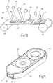
- Fig. 11
- eine diagnostische Bandkassette mit einem darin gelagerten Testband in einer aufgebrochenen perspektivischen Darstellung.
- Das in der Zeichnung dargestellte diagnostische Testband 10 zur Durchführung von Blutzuckertests umfasst ein aufwickelbares flexibles Transportband 12 und eine Vielzahl von darauf für einen sukzessiven Einmalgebrauch bevorrateten, in Bandlängsrichtung voneinander beabstandeten Testelementen bzw. Testfeldern 14, die als im Umriss rechteckförmige etikettenartige Flächengebilde einen auf das Transportband 12 aufgeklebten Trägerstreifen 16, eine darauf aufgebrachte Nachweisschicht 18 und ein die Nachweisschicht 18 an der von dem Trägerstreifen abgewandten Oberseite überspannendes Spreitnetz 20 für eine flächige Verteilung einer von oben auf das Spreitnetz aufgetragenen Probenflüssigkeit (Blutprobe) umfassen. Die Nachweisschicht 18 spricht als Trockenchemiefilm insbesondere auf Enzymbasis auf einen Analyten (Glucose) durch Farbumschlag an, so dass eine photometrische Erfassung durch den transparenten Folienverbund 12, 16 hindurch erfolgen kann.
- Wie aus
Fig. 1 und 2 ersichtlich, ist das als Gewebe 20 ausgebildete streifenförmige Spreitnetz breiter als die Nachweisschicht 18. Die überstehenden Seitenränder 22 des Gewebes 20 sind mit der Oberseite des Trägerstreifens 16 verklebt, der seinerseits als doppelseitiges Klebebandstück auf das Transportband 12 aufgeklebt ist. An ihrer freien Außenseite sind die Seitenränder 22 des Gewebes 20 mit einer hydrophoben Beschichtung 24 versehen, so dass die Flüssigkeitsverteilung bzw. -spreitung gezielt in dem nicht verklebten Zentralbereich 26 des Gewebes 20 über der Nachweisschicht 18 erfolgt. - Die Testfelder 14 lassen sich durch Vorspulen des Transportbandes 12 an einer Applikationsstelle nacheinander zum Einsatz bringen. Aufgrund der dabei ausgeübten Zugkraft ist die flexible Bandstruktur einer Längsdehnung und Querkontraktion unterworfen, was zu einem Abheben bzw. Aufwölben des Zentralbereichs 26 des Gewebes über der Nachweisschicht 18 führen könnte. Dieser Effekt beruht darauf, dass ein in Bandlängsrichtung ausgerichtetes Gewebe durch Bandzugkräfte in seiner Länge, aber nicht in seiner Breite verändert wird, während sich bei dem Trägerband 12 durch Querkontraktion die Breite reduziert.
- Um diesen für eine gleichmäßige Blutverteilung nachteiligen Abhebeeffekt zu vermeiden, ist das Gewebe 20 schräg zu dem Transportband 12 ausgerichtet, wie es in
Fig. 3 veranschaulicht ist. Das Gewebe 20 weist rechtwinklig gekreuzte Gewebefäden 28, 30 auf, die alle schräg zur Bandlängsrichtung bzw. zu den Bandkanten 32 verlaufen. - Zweckmäßig ist das Gewebe 20 in Leinwandbindung aus Kettfäden 28 und Schussfäden 30 gebildet, die in Form von Monofilamenten aus PET bestehen. Für die Verarbeitung von Rollenware ist es günstig, wenn die langen Kettfäden 28 näher zur Bandlängsrichtung als die kurzen Schussfäden 30 verlaufen.
- Die Orientierung des Gewebes 20 lässt sich durch einen Kompensationswinkel α angeben, der durch den kleinsten Winkel zwischen einer Bandkante 30 und den Gewebefäden (also in
Fig. 3 den Kettfäden 28) definiert ist. -
Fig. 4 zeigt die Abhängigkeit der Poissonzahl µ vom Kompensationswinkel α des Gewebes 20. Allgemein gibt die Poissonzahl die Änderung in der Querdimension d im Verhältnis zur Längsdehnung ΔL eines Körpers der Länge L nach folgender Beziehung an:
- Die Schrägausrichtung des Gewebes 20 wird so bestimmt, dass unter einer vorbestimmten Zugbelastung der Unterschied in der Querkontraktion des Transportbands 12 und des Gewebes 20 minimiert ist. Bei einer gegebenen Poissonzahl des Trägerbandes 12 von etwa 0,4 sollte demnach der Kompensationswinkel im Bereich zwischen 20° und 25° liegen.
- Bei den in
Fig. 5 bis 9 gezeigten Ausführungsbeispielen sind gleiche oder ähnliche Teile mit gleichen Bezugszeichen entsprechend der vorstehenden Beschreibung versehen. Das Spreitnetz 20 ist dort anstelle einer Schrägstellung durch eine Abhebesicherung 32 gegen ein Aufwölben bzw. Abheben von der Nachweisschicht 18 gesichert. Diese Abhebesicherung 32 ist bei den verschiedenen Ausführungsbeispielen zusätzlich oder ergänzend zu der seitlichen Verklebung der Seitenränder 22 des Spreitnetzes 20 mit dem Trägerstreifen 16 vorgesehen. Die Ausgestaltung des Spreitnetzes 20 ist hierbei nicht nur auf Gewebe beschränkt, sondern kann auch andere Flachgebilde als Flüssigkeitsverteiler, beispielsweise eine porenhaltige Membrane umfassen. In jedem Fall wird die Abhebesicherung 32 so ausgelegt, dass der Abstand zwischen dem Zentralbereich 26 des Spreitnetzes 20 und der Nachweisschicht 18 unter Einsatzbedingungen des Testbandes maximal 40 µm, vorzugsweise weniger als 20 µm beträgt. - Bei der in
Fig. 5 gezeigten Ausführungsform ist das rechteckförmige Spreitnetz 20 an seinen in Bandlängsrichtung weisenden Stirnenden jeweils durch eine quer durchgehende Laserschweißnaht 34 gesichert. Diese Fixierung kann durch eine Verschmelzung des Netzmaterials beim Laserschneiden der Testfelder 14 erfolgen, wie es nachstehend näher beschrieben ist. - Eine weitere Verbesserung der Robustheit des Testbands 10 ergibt sich dadurch, dass die in
Fig. 2 erkennbare Schräge 36 im Querschnittsverlauf des Spreitnetzes 20 vermieden wird. Dies lässt sich gemäßFig. 6 dadurch realisieren, dass das Spreitnetz 20 breiter als die Nachweisschicht 18 ist und im Bereich seiner überstehenden Seitenränder 22 durch als Abhebesicherung 32 wirkende Klebebandstreifen 36 auf dem Trägerstreifen 16 seitlich abgestützt ist. Die Klebebandstreifen 36 sollten dabei eine im Wesentlichen gleiche Dicke wie die Nachweisschicht 18 aufweisen, so dass das Spreitnetz 20 plan aufliegt. -
Fig. 7 zeigt ein Ausführungsbeispiel, bei dem das Spreitnetz 20 auch stirnseitig über die Nachweisschicht 18 übersteht und an seiner Unterseite durch einen umlaufenden Kleberahmen 38 als Abhebesicherung 32 ringsum auf dem Trägerstreifen 16 fixiert ist. Dies kann durch Laserverschweißung oder eine Kombination von Klebefolien und Laserschweißen erfolgen. Eine Fertigungsmöglichkeit besteht auch darin, eine Klebefolie mit Heißklebepunkten als Zwischenträger in dem Bandfertigungsprozess einzusetzen, um passgenau Klebepunkte an den kurzen und langen Seiten des Kleberahmens 38 zu übertragen. - Bei dem in
Fig. 8 gezeigten Ausführungsbeispiel besitzt das Spreitnetz 20 maximal die gleiche Breite wie die Nachweisschicht 18, so dass sich das Netz im entspannten Zustand nicht wölben kann. Alle Komponenten werden dann über seitliche Klebebänder 40 als Abhebesicherung 32 fixiert. Das Klebeband 40 überlappt somit die Längsränder des Schichtaufbaus 16,18,20, wobei ein zentrales Applikationsfenster 42 zum Auftragen der Flüssigprobe freigehalten wird. Möglich ist es auch, dass der das Applikationsfenster 42 bildende Bereich aus einem quer durchgehenden Klebebandstück 40 ausgestanzt wird. -
Fig. 9 veranschaulicht ein Ausführungsbeispiel, bei dem das Spreitnetz 20 mit einem in Bandquerrichtung verlaufenden biegesteifen Fadensystem 44 als Abhebesicherung 32 versehen ist. Die Querfäden sind dabei so ausgebildet, dass sie sich weitgehend ohne Luftspalt an den Rand der Nachweisschicht 18 anpressen lassen. Dies kann zweckmäßig dadurch ermöglicht werden, dass ein Gewebe 20 mit Schussfäden aus Metall verwendet wird. - Eine weitere Möglichkeit der Robustheitsverbesserung besteht dadurch, ein geeignetes Folienmaterial für den Trägerstreifen 16 zu wählen. Ein solches Material sollte eine Scherfestigkeit im Bereich von 40N/625mm2 (nach DIN EN 1943) besitzen, während die Schälfestigkeit bei etwa 25N/25mm2 (nach DIN EN 1939) liegen sollte. Derartiges Folienmaterial ist beispielsweise unter dem Handelsname Duplocoll VP20242 erhältlich.
- Um eine hohe Fertigungsgeschwindigkeit und -flexiblität bei der Herstellung des Testbandes 10 ermöglichen, ist ein Rolle-Zug-Rolle-Verfahren vorgesehen.
Fig. 10 zeigt eine Vorstufe zur mehrspurigen Fertigung der Testfelder 14. Dabei wird ein doppelseitiges Klebeband über eine Fertigungslinie zwischen zwei Rollen 46,48 transportiert. Darauf werden von Spulen 50 mehrere parallele Nachweisfilme 18' aufgebracht. Die Anordnung wird mit Spreitgewebe 20' belegt, das von weiteren Spulen 52 abgezogen wird. Der Schichtaufbau wird anschließend mittels einer Thermotransferfolie 54 fixiert. Sodann werden mit einem Laser 56 quer verlaufende Laserschnitte eingebracht, welche die parallelen Testfelder 14 stirnseitig voneinander trennen. Der Laser 56 kann durch geeignete Wahl der Parameter nicht nur die Testfelder 14 ablängen, sondern auch die Randbereiche zur Bildung der Schweißnaht 34 (Fig. 5 ) untereinander verkleben. Der gesamte Prozess wird durch Kamerasysteme 58 überwacht, so dass Ausschuss weitgehend vermieden wird. Solchermaßen vorgefertigten Testfelder 14 lassen sich etikettenartig über eine Spendekante auf ein Transportband 12 übertragen und aufkleben, wobei die mehrspurig gefertigten Testbänder 10 dann längsgeteilt werden. - Das Testband 10 wird in Form einer in
Fig. 11 gezeigten Bandkassette 60 als Verbrauchsmaterial in ein Handgerät eingesetzt, um es einem Patienten zu ermöglichen, eine Vielzahl von Glucosetests (beispielsweise 50 Tests) jeweils vor Ort selbst durchzuführen. Die Bandkassette 60 weist hierfür eine Abwickelspule 62 zum Abwickeln von ungebrauchtem Testband und eine Aufwickelspule 64 zum Aufwickeln von gebrauchtem Testband auf, wobei das Testband 10 über eine Applikationsspitze 66 gezogen wird, um dort die Testfelder 14 sukzessive für eine Probenaufnahme bereitzustellen. Weitere Einzelheiten der Messwerterfassung ergeben sich beispielsweise aus derEP-A 1 878 379 , worauf in diesem Zusammenhang ausdrücklich Bezug genommen wird. - Beim Bandtransport wird das Testband unter einem Bandzug von ca. 4N über die Applikationsspitze 66 geführt. Um hierbei einen ungewollten Abhebeeffekt des Spreitnetzes 20 weiter zu verringern, sind die Radien der Umlenkkanten 68 geeignet abzustimmen. Durch eine Vergrößerung der Radien wird der Stress auf den Mehrkomponentenaufbau 12, 14 und damit die Aufwölbung stark verringert. Jedoch führen zu große Radien zu einer Verbreiterung der Spitze 66, und damit zu einer nachteiligen Vergrößerung der Probenauftragsfläche bzw. des benötigten Probenvolumens. In jedem Fall sollte gewährleistet sein, dass zwischen zwei Umlenkkanten 68 plan gespannt wird.
Claims (4)
- Bandkassette umfassend ein diagnostisches Testband für Flüssigproben, insbesondere Körperflüssigkeiten, mit einem auf einer Spule (62,64) aufgewickelten oder aufwickelbaren flexiblen Transportband (12) und einer Vielzahl von auf dem Transportband (12) in Bandlängsrichtung verteilten Testfeldern (14), die einen auf das Transportband (12) aufgebrachten Trägerstreifen (16), eine darauf befindliche Nachweisschicht (18) und ein die Nachweisschicht (18) überspannendes Spreitnetz (20) für eine flächige Flüssigprobenaufnahme umfassen, wobei das Spreitnetz (20) breiter als die Nachweisschicht (18) ist, dadurch gekennzeichnet, dass das Spreitnetz (20) im Bereich seiner über die Nachweisschicht (18) überstehenden Seitenränder (22) durch Klebebandstreifen (36) als Abhebesicherung (32) auf dem Trägerstreifen (16) abgestützt und gegen Abheben von der Nachweisschicht (18) gesichert ist, wobei die Klebebandstreifen (36) und die Nachweisschicht (18) eine im Wesentlichen gleiche Dicke aufweisen, so dass das Spreitnetz (20) stufenfrei abgestützt ist.
- Bandkassette nach Anspruch 1, dadurch gekennzeichnet, dass die Abhebesicherung (32) so ausgelegt ist, dass der Abstand zwischen Spreitnetz (20) und Nachweisschicht (18) unter Einsatzbedingungen maximal 40 Mikrometer, vorzugsweise weniger als 20 Mikrometer beträgt.
- Bandkassette nach Anspruch 1, dadurch gekennzeichnet, dass das Spreitnetz (20) durch einen um die Nachweisschicht (18) umlaufenden Kleberahmen (38) als Abhebesicherung (32) ringsum auf dem Trägerstreifen (16) fixiert ist.
- Bandkassette nach einem der Ansprüche 1 bis 3, dadurch gekennzeichnet, dass der Trägerstreifen (16) aus einem robusten Folienmaterial besteht, dessen Scherfestigkeit mehr als 0,05 N/mm2 beträgt und das eine Schälfestigkeit von mehr als 1 N/mm besitzt.
Priority Applications (4)
| Application Number | Priority Date | Filing Date | Title |
|---|---|---|---|
| PL15203140T PL3025782T3 (pl) | 2009-02-13 | 2010-02-12 | Diagnostyczna taśma testowa do próbek cieczy |
| EP10706571.6A EP2396113B1 (de) | 2009-02-13 | 2010-02-12 | Diagnostisches testband für flüssigproben |
| DK15203140.7T DK3025782T3 (da) | 2009-02-13 | 2010-02-12 | Diagnostisk testbånd til væskeprøver |
| EP15203140.7A EP3025782B1 (de) | 2009-02-13 | 2010-02-12 | Diagnostisches testband für flüssigproben |
Applications Claiming Priority (3)
| Application Number | Priority Date | Filing Date | Title |
|---|---|---|---|
| EP09152837A EP2223746A1 (de) | 2009-02-13 | 2009-02-13 | Diagnostisches Testband für Flüssigproben |
| EP10706571.6A EP2396113B1 (de) | 2009-02-13 | 2010-02-12 | Diagnostisches testband für flüssigproben |
| PCT/EP2010/051811 WO2010092160A1 (de) | 2009-02-13 | 2010-02-12 | Diagnostisches testband für flüssigproben |
Related Child Applications (2)
| Application Number | Title | Priority Date | Filing Date |
|---|---|---|---|
| EP15203140.7A Division EP3025782B1 (de) | 2009-02-13 | 2010-02-12 | Diagnostisches testband für flüssigproben |
| EP15203140.7A Division-Into EP3025782B1 (de) | 2009-02-13 | 2010-02-12 | Diagnostisches testband für flüssigproben |
Publications (2)
| Publication Number | Publication Date |
|---|---|
| EP2396113A1 EP2396113A1 (de) | 2011-12-21 |
| EP2396113B1 true EP2396113B1 (de) | 2016-03-30 |
Family
ID=40672253
Family Applications (3)
| Application Number | Title | Priority Date | Filing Date |
|---|---|---|---|
| EP09152837A Withdrawn EP2223746A1 (de) | 2009-02-13 | 2009-02-13 | Diagnostisches Testband für Flüssigproben |
| EP15203140.7A Active EP3025782B1 (de) | 2009-02-13 | 2010-02-12 | Diagnostisches testband für flüssigproben |
| EP10706571.6A Active EP2396113B1 (de) | 2009-02-13 | 2010-02-12 | Diagnostisches testband für flüssigproben |
Family Applications Before (2)
| Application Number | Title | Priority Date | Filing Date |
|---|---|---|---|
| EP09152837A Withdrawn EP2223746A1 (de) | 2009-02-13 | 2009-02-13 | Diagnostisches Testband für Flüssigproben |
| EP15203140.7A Active EP3025782B1 (de) | 2009-02-13 | 2010-02-12 | Diagnostisches testband für flüssigproben |
Country Status (8)
| Country | Link |
|---|---|
| US (1) | US8404478B2 (de) |
| EP (3) | EP2223746A1 (de) |
| CN (2) | CN105879940A (de) |
| DK (1) | DK3025782T3 (de) |
| ES (2) | ES2796278T3 (de) |
| PL (2) | PL2396113T3 (de) |
| TW (1) | TW201035549A (de) |
| WO (1) | WO2010092160A1 (de) |
Families Citing this family (8)
| Publication number | Priority date | Publication date | Assignee | Title |
|---|---|---|---|---|
| EP2508130A1 (de) * | 2011-04-05 | 2012-10-10 | Roche Diagnostics GmbH | Analysesystem mit Messvorrichtung und Testelement |
| AU2015202837A1 (en) * | 2011-09-16 | 2015-06-11 | F. Hoffmann-La Roche Ag | Test tape cassette and analytical test tape therefor |
| EP2570800B1 (de) * | 2011-09-16 | 2021-01-27 | Roche Diabetes Care GmbH | Testbandkassette mit analytischem Testband |
| ES2545672B2 (es) * | 2012-09-22 | 2016-04-04 | Brandon Bransgrove | Casete y dispositivo analizador |
| CN106214160A (zh) * | 2013-07-31 | 2016-12-14 | 圣铁克私人有限公司 | 用于测量生物流体中的分析物的系统、装置、媒介及方法 |
| WO2020067876A1 (en) * | 2018-09-24 | 2020-04-02 | Lely Patent N.V. | Method of producing a reagent tape, reagent tape and milking device with a milk sampling device therewith |
| CN111624103B (zh) * | 2020-06-08 | 2023-06-20 | 中国计量大学 | 聚合物薄板起拱特性测试装置及方法 |
| US11788918B2 (en) | 2020-06-18 | 2023-10-17 | Trevillyan Labs, Llc | Fluid detection fabric |
Family Cites Families (14)
| Publication number | Priority date | Publication date | Assignee | Title |
|---|---|---|---|---|
| DE2118455B1 (de) * | 1971-04-16 | 1972-09-21 | Boehringer Mannheim Gmbh | Teststreifen |
| DE3118381A1 (de) | 1981-05-09 | 1982-11-25 | Boehringer Mannheim Gmbh, 6800 Mannheim | Mehrschichtiges testmittel zum nachweis einer komponente einer fluessigen probe |
| US4776904A (en) * | 1985-07-19 | 1988-10-11 | Miles Inc. | Multilayer analytical element and method of making, using ultrasonic or laser energy |
| DE3541521A1 (de) * | 1985-11-23 | 1987-06-04 | Sartorius Gmbh | Filter zum filtrieren menschlichen blutes, insbesondere in einem extrakorporalen kreislauf |
| US5411858A (en) * | 1989-05-17 | 1995-05-02 | Actimed Laboratories, Inc. | Manufacturing process for sample initiated assay device |
| DE19629657A1 (de) | 1996-07-23 | 1998-01-29 | Boehringer Mannheim Gmbh | Volumenunabhängiger diagnostischer Testträger und Verfahren zur Bestimmung von Analyt mit dessen Hilfe |
| DE19849024A1 (de) | 1998-10-23 | 2000-04-27 | Roche Diagnostics Gmbh | Funktionelle Auflage für flexible Objekte, insbesondere für diagnostische Teststreifen |
| DE10346417A1 (de) * | 2003-10-07 | 2005-06-02 | Roche Diagnostics Gmbh | Analytisches Testelement umfassend ein Netzwerk zur Bildung eines Kapillarkanals |
| AU2005201576B2 (en) * | 2004-05-07 | 2010-06-24 | F. Hoffmann-La Roche Ag | Process and device for producing an analytical tape for liquid samples |
| JP4505296B2 (ja) * | 2004-09-17 | 2010-07-21 | 富士フイルム株式会社 | 液体試料分析用多層分析素子 |
| CN2730785Y (zh) * | 2004-10-08 | 2005-10-05 | 沈普 | 一种复合纸箱板 |
| PL1834696T3 (pl) | 2006-03-14 | 2013-08-30 | Hoffmann La Roche | Sposób wytwarzania wielowarstwowego elementu analitycznego |
| EP1878379B1 (de) | 2006-07-11 | 2019-10-16 | F. Hoffmann-La Roche AG | Testbandsystem, insbesondere für Blutzuckeranalyse |
| US20090241783A1 (en) * | 2006-09-20 | 2009-10-01 | Teijin Fibers Limited | Filter for extracting one's favorite drink and bag for extracting one's favorite drink |
-
2009
- 2009-02-13 EP EP09152837A patent/EP2223746A1/de not_active Withdrawn
-
2010
- 2010-02-02 TW TW099103022A patent/TW201035549A/zh unknown
- 2010-02-12 PL PL10706571.6T patent/PL2396113T3/pl unknown
- 2010-02-12 CN CN201610230196.2A patent/CN105879940A/zh active Pending
- 2010-02-12 DK DK15203140.7T patent/DK3025782T3/da active
- 2010-02-12 ES ES15203140T patent/ES2796278T3/es active Active
- 2010-02-12 ES ES10706571T patent/ES2571984T3/es active Active
- 2010-02-12 WO PCT/EP2010/051811 patent/WO2010092160A1/de not_active Ceased
- 2010-02-12 CN CN201080007513.5A patent/CN102316987B/zh active Active
- 2010-02-12 PL PL15203140T patent/PL3025782T3/pl unknown
- 2010-02-12 EP EP15203140.7A patent/EP3025782B1/de active Active
- 2010-02-12 EP EP10706571.6A patent/EP2396113B1/de active Active
-
2011
- 2011-08-09 US US13/205,886 patent/US8404478B2/en active Active
Also Published As
| Publication number | Publication date |
|---|---|
| CN102316987B (zh) | 2016-09-28 |
| ES2571984T3 (es) | 2016-05-27 |
| PL3025782T3 (pl) | 2020-07-13 |
| CN102316987A (zh) | 2012-01-11 |
| PL2396113T3 (pl) | 2016-09-30 |
| EP2396113A1 (de) | 2011-12-21 |
| WO2010092160A1 (de) | 2010-08-19 |
| EP3025782B1 (de) | 2020-04-01 |
| EP2223746A1 (de) | 2010-09-01 |
| DK3025782T3 (da) | 2020-06-15 |
| US20120045825A1 (en) | 2012-02-23 |
| TW201035549A (en) | 2010-10-01 |
| ES2796278T3 (es) | 2020-11-26 |
| CN105879940A (zh) | 2016-08-24 |
| US8404478B2 (en) | 2013-03-26 |
| HK1163590A1 (zh) | 2012-09-14 |
| EP3025782A1 (de) | 2016-06-01 |
Similar Documents
| Publication | Publication Date | Title |
|---|---|---|
| EP3025782B1 (de) | Diagnostisches testband für flüssigproben | |
| EP0297389B1 (de) | Diagnostischer Testträger und Verfahren zu dessen Herstellung | |
| DE10315544B4 (de) | Verfahren zur Herstellung einer Stech- und Mess-Vorrichtung sowie Vorrichtung | |
| DE3523439A1 (de) | Testtraeger | |
| EP2570800B1 (de) | Testbandkassette mit analytischem Testband | |
| EP0805193A1 (de) | Verfahren zur Verbindung einer Metallfolie mit einer Kunststofffolie | |
| DE1297354B (de) | Mehrschichtiges, bandfoermiges Klebematerial zum Bestuecken von Karten mit Diapositiven sowie Verfahren zum Herstellen des Klebematerials | |
| EP3268525B1 (de) | Verfahren und vorrichtung zur herstellung eines webblatts und webblatt | |
| DE19942928C2 (de) | Teststreifen | |
| EP0692445B1 (de) | Anordnung zum Befestigen eines Anfanges einer Papierbahn einer Vorratspapierbahnrolle | |
| DE102004054121A1 (de) | Träger für Stickereifolie | |
| WO1989008907A1 (fr) | Porte-etiquette a bandes et son dispositif de fabrication | |
| DE69700761T2 (de) | Verfahren zum Anbringen eines metallischen Drahtes oder Bandes auf einem dünnen Blatt und Rolle von diesem Blatt | |
| DE4442920C2 (de) | Verfahren zur Herstellung eines Folienverbundes | |
| EP2103934B1 (de) | Verfahren zum Herstellen einer diagnostischen Bandeinheit | |
| EP1801584A1 (de) | Analysesystem für Körperflüssigkeiten | |
| EP1734365A1 (de) | Körperflüssigkeit-Analysevorrichtung mit einem Testfelder aufweisenden Testband | |
| EP2376911B1 (de) | Gefaltetes trägerband mit verbrauchselementen | |
| DE102007044515A1 (de) | Verfahren und Vorrichtung zur Herstellung von Rollosystemen | |
| CH698648B1 (de) | Vorrichtung zum herstellen laminierter produkte. | |
| WO2019025107A1 (de) | Deckelstabsystem | |
| WO2004088379A1 (de) | Spleissschutz für lichtleiter mit einer trägerfolie und vorrichtung zum anbringen des spleissschutzes an den lichtleiter | |
| DE29518176U1 (de) | Einrichtung zum horizontalen Abrollen von Werbeanzeigen auf Papier oder anderen Druckträgern | |
| DE19949253A1 (de) | Vorrichtung zur Herstellung naßkaschierter Mehrschicht-Laminate |
Legal Events
| Date | Code | Title | Description |
|---|---|---|---|
| PUAI | Public reference made under article 153(3) epc to a published international application that has entered the european phase |
Free format text: ORIGINAL CODE: 0009012 |
|
| 17P | Request for examination filed |
Effective date: 20110908 |
|
| AK | Designated contracting states |
Kind code of ref document: A1 Designated state(s): AT BE BG CH CY CZ DE DK EE ES FI FR GB GR HR HU IE IS IT LI LT LU LV MC MK MT NL NO PL PT RO SE SI SK SM TR |
|
| DAX | Request for extension of the european patent (deleted) | ||
| GRAP | Despatch of communication of intention to grant a patent |
Free format text: ORIGINAL CODE: EPIDOSNIGR1 |
|
| INTG | Intention to grant announced |
Effective date: 20150925 |
|
| GRAS | Grant fee paid |
Free format text: ORIGINAL CODE: EPIDOSNIGR3 |
|
| GRAA | (expected) grant |
Free format text: ORIGINAL CODE: 0009210 |
|
| AK | Designated contracting states |
Kind code of ref document: B1 Designated state(s): AT BE BG CH CY CZ DE DK EE ES FI FR GB GR HR HU IE IS IT LI LT LU LV MC MK MT NL NO PL PT RO SE SI SK SM TR |
|
| REG | Reference to a national code |
Ref country code: GB Ref legal event code: FG4D Free format text: NOT ENGLISH |
|
| REG | Reference to a national code |
Ref country code: CH Ref legal event code: EP |
|
| REG | Reference to a national code |
Ref country code: AT Ref legal event code: REF Ref document number: 784768 Country of ref document: AT Kind code of ref document: T Effective date: 20160415 |
|
| REG | Reference to a national code |
Ref country code: IE Ref legal event code: FG4D Free format text: LANGUAGE OF EP DOCUMENT: GERMAN |
|
| REG | Reference to a national code |
Ref country code: DE Ref legal event code: R096 Ref document number: 502010011331 Country of ref document: DE |
|
| REG | Reference to a national code |
Ref country code: ES Ref legal event code: FG2A Ref document number: 2571984 Country of ref document: ES Kind code of ref document: T3 Effective date: 20160527 |
|
| REG | Reference to a national code |
Ref country code: NL Ref legal event code: FP |
|
| REG | Reference to a national code |
Ref country code: LT Ref legal event code: MG4D |
|
| PG25 | Lapsed in a contracting state [announced via postgrant information from national office to epo] |
Ref country code: HR Free format text: LAPSE BECAUSE OF FAILURE TO SUBMIT A TRANSLATION OF THE DESCRIPTION OR TO PAY THE FEE WITHIN THE PRESCRIBED TIME-LIMIT Effective date: 20160330 Ref country code: FI Free format text: LAPSE BECAUSE OF FAILURE TO SUBMIT A TRANSLATION OF THE DESCRIPTION OR TO PAY THE FEE WITHIN THE PRESCRIBED TIME-LIMIT Effective date: 20160330 Ref country code: NO Free format text: LAPSE BECAUSE OF FAILURE TO SUBMIT A TRANSLATION OF THE DESCRIPTION OR TO PAY THE FEE WITHIN THE PRESCRIBED TIME-LIMIT Effective date: 20160630 Ref country code: GR Free format text: LAPSE BECAUSE OF FAILURE TO SUBMIT A TRANSLATION OF THE DESCRIPTION OR TO PAY THE FEE WITHIN THE PRESCRIBED TIME-LIMIT Effective date: 20160701 |
|
| PG25 | Lapsed in a contracting state [announced via postgrant information from national office to epo] |
Ref country code: LT Free format text: LAPSE BECAUSE OF FAILURE TO SUBMIT A TRANSLATION OF THE DESCRIPTION OR TO PAY THE FEE WITHIN THE PRESCRIBED TIME-LIMIT Effective date: 20160330 Ref country code: LV Free format text: LAPSE BECAUSE OF FAILURE TO SUBMIT A TRANSLATION OF THE DESCRIPTION OR TO PAY THE FEE WITHIN THE PRESCRIBED TIME-LIMIT Effective date: 20160330 Ref country code: SE Free format text: LAPSE BECAUSE OF FAILURE TO SUBMIT A TRANSLATION OF THE DESCRIPTION OR TO PAY THE FEE WITHIN THE PRESCRIBED TIME-LIMIT Effective date: 20160330 |
|
| PG25 | Lapsed in a contracting state [announced via postgrant information from national office to epo] |
Ref country code: EE Free format text: LAPSE BECAUSE OF FAILURE TO SUBMIT A TRANSLATION OF THE DESCRIPTION OR TO PAY THE FEE WITHIN THE PRESCRIBED TIME-LIMIT Effective date: 20160330 Ref country code: IS Free format text: LAPSE BECAUSE OF FAILURE TO SUBMIT A TRANSLATION OF THE DESCRIPTION OR TO PAY THE FEE WITHIN THE PRESCRIBED TIME-LIMIT Effective date: 20160730 |
|
| PG25 | Lapsed in a contracting state [announced via postgrant information from national office to epo] |
Ref country code: PT Free format text: LAPSE BECAUSE OF FAILURE TO SUBMIT A TRANSLATION OF THE DESCRIPTION OR TO PAY THE FEE WITHIN THE PRESCRIBED TIME-LIMIT Effective date: 20160801 Ref country code: SK Free format text: LAPSE BECAUSE OF FAILURE TO SUBMIT A TRANSLATION OF THE DESCRIPTION OR TO PAY THE FEE WITHIN THE PRESCRIBED TIME-LIMIT Effective date: 20160330 Ref country code: RO Free format text: LAPSE BECAUSE OF FAILURE TO SUBMIT A TRANSLATION OF THE DESCRIPTION OR TO PAY THE FEE WITHIN THE PRESCRIBED TIME-LIMIT Effective date: 20160330 Ref country code: SM Free format text: LAPSE BECAUSE OF FAILURE TO SUBMIT A TRANSLATION OF THE DESCRIPTION OR TO PAY THE FEE WITHIN THE PRESCRIBED TIME-LIMIT Effective date: 20160330 Ref country code: CZ Free format text: LAPSE BECAUSE OF FAILURE TO SUBMIT A TRANSLATION OF THE DESCRIPTION OR TO PAY THE FEE WITHIN THE PRESCRIBED TIME-LIMIT Effective date: 20160330 |
|
| REG | Reference to a national code |
Ref country code: DE Ref legal event code: R097 Ref document number: 502010011331 Country of ref document: DE |
|
| REG | Reference to a national code |
Ref country code: FR Ref legal event code: PLFP Year of fee payment: 8 |
|
| PG25 | Lapsed in a contracting state [announced via postgrant information from national office to epo] |
Ref country code: DK Free format text: LAPSE BECAUSE OF FAILURE TO SUBMIT A TRANSLATION OF THE DESCRIPTION OR TO PAY THE FEE WITHIN THE PRESCRIBED TIME-LIMIT Effective date: 20160330 |
|
| PLBE | No opposition filed within time limit |
Free format text: ORIGINAL CODE: 0009261 |
|
| STAA | Information on the status of an ep patent application or granted ep patent |
Free format text: STATUS: NO OPPOSITION FILED WITHIN TIME LIMIT |
|
| 26N | No opposition filed |
Effective date: 20170103 |
|
| PG25 | Lapsed in a contracting state [announced via postgrant information from national office to epo] |
Ref country code: SI Free format text: LAPSE BECAUSE OF FAILURE TO SUBMIT A TRANSLATION OF THE DESCRIPTION OR TO PAY THE FEE WITHIN THE PRESCRIBED TIME-LIMIT Effective date: 20160330 Ref country code: BE Free format text: LAPSE BECAUSE OF NON-PAYMENT OF DUE FEES Effective date: 20170228 |
|
| PG25 | Lapsed in a contracting state [announced via postgrant information from national office to epo] |
Ref country code: MC Free format text: LAPSE BECAUSE OF FAILURE TO SUBMIT A TRANSLATION OF THE DESCRIPTION OR TO PAY THE FEE WITHIN THE PRESCRIBED TIME-LIMIT Effective date: 20160330 |
|
| REG | Reference to a national code |
Ref country code: CH Ref legal event code: PL |
|
| PG25 | Lapsed in a contracting state [announced via postgrant information from national office to epo] |
Ref country code: CH Free format text: LAPSE BECAUSE OF NON-PAYMENT OF DUE FEES Effective date: 20170228 Ref country code: LI Free format text: LAPSE BECAUSE OF NON-PAYMENT OF DUE FEES Effective date: 20170228 |
|
| REG | Reference to a national code |
Ref country code: IE Ref legal event code: MM4A |
|
| PG25 | Lapsed in a contracting state [announced via postgrant information from national office to epo] |
Ref country code: LU Free format text: LAPSE BECAUSE OF NON-PAYMENT OF DUE FEES Effective date: 20170212 |
|
| REG | Reference to a national code |
Ref country code: FR Ref legal event code: PLFP Year of fee payment: 9 |
|
| REG | Reference to a national code |
Ref country code: BE Ref legal event code: MM Effective date: 20170228 |
|
| PG25 | Lapsed in a contracting state [announced via postgrant information from national office to epo] |
Ref country code: IE Free format text: LAPSE BECAUSE OF NON-PAYMENT OF DUE FEES Effective date: 20170212 |
|
| REG | Reference to a national code |
Ref country code: AT Ref legal event code: MM01 Ref document number: 784768 Country of ref document: AT Kind code of ref document: T Effective date: 20170212 |
|
| PG25 | Lapsed in a contracting state [announced via postgrant information from national office to epo] |
Ref country code: AT Free format text: LAPSE BECAUSE OF NON-PAYMENT OF DUE FEES Effective date: 20170212 |
|
| PG25 | Lapsed in a contracting state [announced via postgrant information from national office to epo] |
Ref country code: MT Free format text: LAPSE BECAUSE OF FAILURE TO SUBMIT A TRANSLATION OF THE DESCRIPTION OR TO PAY THE FEE WITHIN THE PRESCRIBED TIME-LIMIT Effective date: 20160330 |
|
| PG25 | Lapsed in a contracting state [announced via postgrant information from national office to epo] |
Ref country code: HU Free format text: LAPSE BECAUSE OF FAILURE TO SUBMIT A TRANSLATION OF THE DESCRIPTION OR TO PAY THE FEE WITHIN THE PRESCRIBED TIME-LIMIT; INVALID AB INITIO Effective date: 20100212 |
|
| PG25 | Lapsed in a contracting state [announced via postgrant information from national office to epo] |
Ref country code: BG Free format text: LAPSE BECAUSE OF FAILURE TO SUBMIT A TRANSLATION OF THE DESCRIPTION OR TO PAY THE FEE WITHIN THE PRESCRIBED TIME-LIMIT Effective date: 20160330 |
|
| PG25 | Lapsed in a contracting state [announced via postgrant information from national office to epo] |
Ref country code: CY Free format text: LAPSE BECAUSE OF NON-PAYMENT OF DUE FEES Effective date: 20160330 |
|
| PG25 | Lapsed in a contracting state [announced via postgrant information from national office to epo] |
Ref country code: MK Free format text: LAPSE BECAUSE OF FAILURE TO SUBMIT A TRANSLATION OF THE DESCRIPTION OR TO PAY THE FEE WITHIN THE PRESCRIBED TIME-LIMIT Effective date: 20160330 |
|
| PG25 | Lapsed in a contracting state [announced via postgrant information from national office to epo] |
Ref country code: TR Free format text: LAPSE BECAUSE OF FAILURE TO SUBMIT A TRANSLATION OF THE DESCRIPTION OR TO PAY THE FEE WITHIN THE PRESCRIBED TIME-LIMIT Effective date: 20160330 |
|
| PGFP | Annual fee paid to national office [announced via postgrant information from national office to epo] |
Ref country code: NL Payment date: 20250121 Year of fee payment: 16 |
|
| PGFP | Annual fee paid to national office [announced via postgrant information from national office to epo] |
Ref country code: DE Payment date: 20250122 Year of fee payment: 16 |
|
| PGFP | Annual fee paid to national office [announced via postgrant information from national office to epo] |
Ref country code: ES Payment date: 20250303 Year of fee payment: 16 |
|
| PGFP | Annual fee paid to national office [announced via postgrant information from national office to epo] |
Ref country code: PL Payment date: 20250122 Year of fee payment: 16 Ref country code: FR Payment date: 20250122 Year of fee payment: 16 |
|
| PGFP | Annual fee paid to national office [announced via postgrant information from national office to epo] |
Ref country code: GB Payment date: 20250124 Year of fee payment: 16 Ref country code: IT Payment date: 20250121 Year of fee payment: 16 |