EP2394822B1 - Pneu comportant une structure de renfort de sommet en zigzag, en particulier un pneu d'avion à poids réduit - Google Patents
Pneu comportant une structure de renfort de sommet en zigzag, en particulier un pneu d'avion à poids réduit Download PDFInfo
- Publication number
- EP2394822B1 EP2394822B1 EP11168675.4A EP11168675A EP2394822B1 EP 2394822 B1 EP2394822 B1 EP 2394822B1 EP 11168675 A EP11168675 A EP 11168675A EP 2394822 B1 EP2394822 B1 EP 2394822B1
- Authority
- EP
- European Patent Office
- Prior art keywords
- belt
- tire
- belt layer
- zigzag
- reinforcing structure
- Prior art date
- Legal status (The legal status is an assumption and is not a legal conclusion. Google has not performed a legal analysis and makes no representation as to the accuracy of the status listed.)
- Active
Links
Images

Classifications
-
- B—PERFORMING OPERATIONS; TRANSPORTING
- B60—VEHICLES IN GENERAL
- B60C—VEHICLE TYRES; TYRE INFLATION; TYRE CHANGING; CONNECTING VALVES TO INFLATABLE ELASTIC BODIES IN GENERAL; DEVICES OR ARRANGEMENTS RELATED TO TYRES
- B60C9/00—Reinforcements or ply arrangement of pneumatic tyres
- B60C9/18—Structure or arrangement of belts or breakers, crown-reinforcing or cushioning layers
- B60C9/26—Folded plies
- B60C9/263—Folded plies further characterised by an endless zigzag configuration in at least one belt ply, i.e. no cut edge being present
-
- B—PERFORMING OPERATIONS; TRANSPORTING
- B60—VEHICLES IN GENERAL
- B60C—VEHICLE TYRES; TYRE INFLATION; TYRE CHANGING; CONNECTING VALVES TO INFLATABLE ELASTIC BODIES IN GENERAL; DEVICES OR ARRANGEMENTS RELATED TO TYRES
- B60C9/00—Reinforcements or ply arrangement of pneumatic tyres
- B60C9/18—Structure or arrangement of belts or breakers, crown-reinforcing or cushioning layers
- B60C9/20—Structure or arrangement of belts or breakers, crown-reinforcing or cushioning layers built-up from rubberised plies each having all cords arranged substantially parallel
- B60C2009/2012—Structure or arrangement of belts or breakers, crown-reinforcing or cushioning layers built-up from rubberised plies each having all cords arranged substantially parallel with particular configuration of the belt cords in the respective belt layers
- B60C2009/2016—Structure or arrangement of belts or breakers, crown-reinforcing or cushioning layers built-up from rubberised plies each having all cords arranged substantially parallel with particular configuration of the belt cords in the respective belt layers comprising cords at an angle of 10 to 30 degrees to the circumferential direction
-
- B—PERFORMING OPERATIONS; TRANSPORTING
- B60—VEHICLES IN GENERAL
- B60C—VEHICLE TYRES; TYRE INFLATION; TYRE CHANGING; CONNECTING VALVES TO INFLATABLE ELASTIC BODIES IN GENERAL; DEVICES OR ARRANGEMENTS RELATED TO TYRES
- B60C9/00—Reinforcements or ply arrangement of pneumatic tyres
- B60C9/18—Structure or arrangement of belts or breakers, crown-reinforcing or cushioning layers
- B60C9/20—Structure or arrangement of belts or breakers, crown-reinforcing or cushioning layers built-up from rubberised plies each having all cords arranged substantially parallel
- B60C2009/2035—Structure or arrangement of belts or breakers, crown-reinforcing or cushioning layers built-up from rubberised plies each having all cords arranged substantially parallel built-up by narrow strips
-
- B—PERFORMING OPERATIONS; TRANSPORTING
- B60—VEHICLES IN GENERAL
- B60C—VEHICLE TYRES; TYRE INFLATION; TYRE CHANGING; CONNECTING VALVES TO INFLATABLE ELASTIC BODIES IN GENERAL; DEVICES OR ARRANGEMENTS RELATED TO TYRES
- B60C9/00—Reinforcements or ply arrangement of pneumatic tyres
- B60C9/18—Structure or arrangement of belts or breakers, crown-reinforcing or cushioning layers
- B60C9/20—Structure or arrangement of belts or breakers, crown-reinforcing or cushioning layers built-up from rubberised plies each having all cords arranged substantially parallel
- B60C2009/2074—Physical properties or dimension of the belt cord
- B60C2009/2077—Diameters of the cords; Linear density thereof
-
- B—PERFORMING OPERATIONS; TRANSPORTING
- B60—VEHICLES IN GENERAL
- B60C—VEHICLE TYRES; TYRE INFLATION; TYRE CHANGING; CONNECTING VALVES TO INFLATABLE ELASTIC BODIES IN GENERAL; DEVICES OR ARRANGEMENTS RELATED TO TYRES
- B60C9/00—Reinforcements or ply arrangement of pneumatic tyres
- B60C9/18—Structure or arrangement of belts or breakers, crown-reinforcing or cushioning layers
- B60C9/20—Structure or arrangement of belts or breakers, crown-reinforcing or cushioning layers built-up from rubberised plies each having all cords arranged substantially parallel
- B60C2009/2074—Physical properties or dimension of the belt cord
- B60C2009/209—Tensile strength
-
- B—PERFORMING OPERATIONS; TRANSPORTING
- B60—VEHICLES IN GENERAL
- B60C—VEHICLE TYRES; TYRE INFLATION; TYRE CHANGING; CONNECTING VALVES TO INFLATABLE ELASTIC BODIES IN GENERAL; DEVICES OR ARRANGEMENTS RELATED TO TYRES
- B60C9/00—Reinforcements or ply arrangement of pneumatic tyres
- B60C9/18—Structure or arrangement of belts or breakers, crown-reinforcing or cushioning layers
- B60C9/20—Structure or arrangement of belts or breakers, crown-reinforcing or cushioning layers built-up from rubberised plies each having all cords arranged substantially parallel
- B60C2009/2074—Physical properties or dimension of the belt cord
- B60C2009/2093—Elongation of the reinforcements at break point
-
- B—PERFORMING OPERATIONS; TRANSPORTING
- B60—VEHICLES IN GENERAL
- B60C—VEHICLE TYRES; TYRE INFLATION; TYRE CHANGING; CONNECTING VALVES TO INFLATABLE ELASTIC BODIES IN GENERAL; DEVICES OR ARRANGEMENTS RELATED TO TYRES
- B60C9/00—Reinforcements or ply arrangement of pneumatic tyres
- B60C9/18—Structure or arrangement of belts or breakers, crown-reinforcing or cushioning layers
- B60C9/26—Folded plies
- B60C9/263—Folded plies further characterised by an endless zigzag configuration in at least one belt ply, i.e. no cut edge being present
- B60C2009/266—Folded plies further characterised by an endless zigzag configuration in at least one belt ply, i.e. no cut edge being present combined with non folded cut-belt plies
-
- B—PERFORMING OPERATIONS; TRANSPORTING
- B60—VEHICLES IN GENERAL
- B60C—VEHICLE TYRES; TYRE INFLATION; TYRE CHANGING; CONNECTING VALVES TO INFLATABLE ELASTIC BODIES IN GENERAL; DEVICES OR ARRANGEMENTS RELATED TO TYRES
- B60C2200/00—Tyres specially adapted for particular applications
- B60C2200/02—Tyres specially adapted for particular applications for aircrafts
-
- B—PERFORMING OPERATIONS; TRANSPORTING
- B60—VEHICLES IN GENERAL
- B60C—VEHICLE TYRES; TYRE INFLATION; TYRE CHANGING; CONNECTING VALVES TO INFLATABLE ELASTIC BODIES IN GENERAL; DEVICES OR ARRANGEMENTS RELATED TO TYRES
- B60C9/00—Reinforcements or ply arrangement of pneumatic tyres
- B60C9/18—Structure or arrangement of belts or breakers, crown-reinforcing or cushioning layers
- B60C9/20—Structure or arrangement of belts or breakers, crown-reinforcing or cushioning layers built-up from rubberised plies each having all cords arranged substantially parallel
- B60C9/22—Structure or arrangement of belts or breakers, crown-reinforcing or cushioning layers built-up from rubberised plies each having all cords arranged substantially parallel the plies being arranged with all cords disposed along the circumference of the tyre
- B60C9/2204—Structure or arrangement of belts or breakers, crown-reinforcing or cushioning layers built-up from rubberised plies each having all cords arranged substantially parallel the plies being arranged with all cords disposed along the circumference of the tyre obtained by circumferentially narrow strip winding
-
- Y—GENERAL TAGGING OF NEW TECHNOLOGICAL DEVELOPMENTS; GENERAL TAGGING OF CROSS-SECTIONAL TECHNOLOGIES SPANNING OVER SEVERAL SECTIONS OF THE IPC; TECHNICAL SUBJECTS COVERED BY FORMER USPC CROSS-REFERENCE ART COLLECTIONS [XRACs] AND DIGESTS
- Y10—TECHNICAL SUBJECTS COVERED BY FORMER USPC
- Y10T—TECHNICAL SUBJECTS COVERED BY FORMER US CLASSIFICATION
- Y10T152/00—Resilient tires and wheels
- Y10T152/10—Tires, resilient
- Y10T152/10495—Pneumatic tire or inner tube
- Y10T152/10765—Characterized by belt or breaker structure
- Y10T152/10783—Reinforcing plies made up from wound narrow ribbons
Definitions
- This invention relates to a pneumatic tire having a carcass and a belt reinforcing structure and more particularly to a high speed heavy load tire such as an aircraft tire.
- Pneumatic tires for high speed applications experience a high degree of flexure in the crown area of the tire as the tire enters and leaves the area of the footprint. This problem is particularly exacerbated on aircraft tires wherein the tires can reach speed of over 320 km/h at takeoff and landing.
- the crown area tends to grow in dimension due to the high angular accelerations and velocity, tending to pull the tread area radially outwardly. Counteracting these forces is the load of the vehicle which is only supported in the small area of the tire known as the footprint area.
- EP-A- 1 449 680 describes a tire in accordance with the preamble of claim 1.
- the invention relates to a tire in accordance with claim 1.
- Dependent claims refer to preferred embodiments of the invention.
- the belt reinforcing structure comprises a first and second belt layer having cords arranged at an angle of 5 degrees or less with respect to the midcircumferential plane, and a zigzag belt reinforcing structure located radially outward of the first belt layer, the zigzag belt reinforcing structure forming two layers of cords, the cords inclined at 5 to 30 degrees relative to the centerplane of the tire extending in alternation to turnaround points at each lateral edge, wherein the first belt layer is wider than the zigzag belt reinforcing structure, and the second belt layer is narrower than the zigzag belt structure.
- the second belt layer has a width less than the first belt layer.
- the first and second belt layers are formed from helically winding the cords forming two spiral layers.
- the ratio of the zigzag belt width Wz to the widest belt layer width Ws is in the range of about 0.6 ⁇ Wz/Ws ⁇ 1.0
- one or more of the belts comprise cords made of a nylon and aramid blend.
- one or more of the belts comprise cords made of aramid.
- the tire further comprises a third belt layer located radially inward of the first and second belt layers, wherein the third belt layer has a width less than the first belt layer and a width less than the second belt layer.
- the belt structure comprises two radially inner spiral belt layers, two zigzag belt structures and two radially outer spiral belt layers.
- At least one belt ply layer has cords having a percent elongation at break greater than 11 %, and a break strength greater than 900N with an original linear density of greater than 8500 dtex.
- the belt reinforcing structure comprises a first belt layer having cords arranged at an angle of 5 degrees or less with respect to the midcircumferential plane, a second belt layer located radially inward of said first belt layer and having a width less than the first belt layer, and a third belt layer located radially inward of the second belt layer and having a width greater than the second belt layer, and a zigzag belt reinforcing structure located radially outward of the first belt layer, the zigzag belt reinforcing structure forming two layers of cords, the cords inclined at 5 to 30 degrees relative to the centerplane of the tire extending in alternation to turnaround points at each lateral edge, wherein one of the first, second and third belt layers is wider than the zigzag belt reinforcing structure.
- the radial carcass ply cord fiber is nylon.
- Carcass means the tire structure apart from the belt structure, tread, undertread, and sidewall rubber over the plies, but including the beads.
- “Circumferential” means lines or directions extending along the perimeter of the surface of the annular tread perpendicular to the axial direction.
- Core means one of the reinforcement strands which the plies in the tire comprise.
- Equatorial plane means the plane perpendicular to the tire's axis of rotation and passing through the center of its tread.
- Ply means a continuous layer of rubber-coated parallel cords.
- Ring and radially mean directions radially toward or away from the axis of rotation of the tire.
- Ring-ply tire means a belted or circumferentially-restricted pneumatic tire in which the ply cords which extend from bead to bead are laid at cord angles preferably between 65°and 90°with respect to the equatorial plane of the tire.
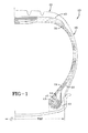
- Figure 1 illustrates a cross-sectional view of one half of a radial aircraft tire 10 as an embodiment of the present invention.
- the tire is symmetrical about the mid-circumferential plane so that only one half is illustrated.
- the aircraft tire comprises a pair of bead portions 12 each containing a bead core 14 embedded therein.
- a bead core suitable for use in an aircraft tire is described in US-B-6,571,847 .
- the bead core 14 preferably has an aluminum, aluminum alloy or other light weight alloy in the center portion 13 surrounded by a plurality of steel sheath wires 15.
- a person skilled in the art may appreciate that other bead cores may also be utilized.
- the aircraft tire further comprises a sidewall portion 16 extending substantially outward from each of the bead portions 12 in the radial direction of the tire, and a tread portion 20 extending between the radially outer ends of the sidewall portions 16. Furthermore, the tire 10 is reinforced with a carcass 22 toroidally extending from one of the bead portions 12 to the other bead portion 12.
- the carcass 22 preferably comprises inner carcass plies 24 and outer carcass plies 26, preferably oriented in the radial direction.
- each of these carcass plies 24,26 may comprise any suitable cord, typically nylon cords such as nylon-6,6 cords extending substantially perpendicular to an equatorial plane EP of the tire (i.e. extending in the radial direction of the tire).
- nylon cords Preferably the nylon cords have an 1890 denier/2/2 or 1890 denier/3 construction.
- One or more of the carcass plies 24, 26 may also comprise an aramid and nylon cord structure, for example, a hybrid cord, a high energy cord or a merged cord. Examples of suitable cords are described in US-A-4,893,665 , US-A-4,155,394 or US-B-6,799,618 .
- the tire 10 further comprises a belt package 40 arranged between the carcass 22 and the tread rubber 20.
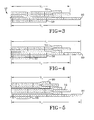
- Figure 3 illustrates a first embodiment of one half of a belt package 40 suitable for use in the tire, preferably the aircraft tire.
- the belt package 40 is symmetrical about the mid-circumferential plane so that only one half of the belt package is illustrated.
- the belt package 40 as shown comprises a second belt layer 50 located adjacent the carcass.
- the second belt layer 50 is preferably formed of cords having an angle of +/- 5 degrees or less with respect to the mid-circumferential plane.
- the second belt layer 50 is formed of a rubberized strip 43 of two or more cords made by spirally or helically winding the cords at an angle of plus or minus 5 degrees or less, such as about 1 degree, relative to the circumferential direction.
- the second belt layer 50 is the narrowest belt structure of the belt package 40, and more preferably has a width in the range of 13% to 100%, alternatively 60% to 100% or 80% to 90%, of the rim width (width between flanges).
- the belt package 40 further comprises a first belt layer 60 located radially outward of the second belt layer 50.
- the first belt layer 60 is preferably formed of cords having an angle of +/- 5 degrees or less, such as about 1 degree, with respect to the mid-circumferential plane.
- the first belt layer 60 is formed of a rubberized strip 43 of two or more cords made by spirally or helically winding the cords at an angle of plus or minus 5 degrees or less relative to the circumferential direction.
- the first belt layer 60 has a width in the range of 101 % to 120% of the rim width and/or has a width greater than the second belt layer 50. More preferably, the first belt layer 60 is the widest belt layer of the belt package 40.
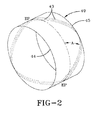
- the belt package 40 further comprises at least one zigzag belt reinforcing structure 70.
- the zigzag belt reinforcing structure 70 comprises of two layers of cord interwoven together formed as shown in Figure 2 .
- the zigzag belt structure 70 is formed from a rubberized strip 43 of one or more cords 46 that is wound generally in the circumferential direction while being inclined to extend between alternating lateral edges 44 and 45 of a tire building drum 49 or core.
- the strip 43 is wound along such zigzag path many times while the strip 43 is shifted a desired amount in the circumferential direction so as preferably not to form a gap between the adjoining strips 43.
- the cords extend in the circumferential direction while changing the bending direction at a turnaround point at both ends 44, 45.
- the cords of the zigzag belt structure cross with each other, typically at a cord angle A of 5 degrees to 30 degrees with respect to the equatorial plane EP of the tire when the strip 43 is reciprocated at least once between both side ends 44 and 45 of the ply within every 360 degrees of the circumference as mentioned above.
- the two layers of cords formed in each zigzag belt structure are embedded and inseparable in the belt structure and there are no cut ends at the outer lateral ends of the belt.
- the zigzag belt reinforcing structure 70 comprises at least two layers of cords or a ribbon of parallel cords having 1 to 20 cords in each ribbon and laid up in an alternating pattern extending at an angle between 5° and 30° between lateral edges of the belt layers.
- the zigzag belt structure 70 is the most radially outward belt structure of the belt package 40. It is additionally preferred that there is only one zigzag belt structure 70.
- the zigzag belt structure 70 is preferably wider than the second belt layer 50, but has a width less than the first belt layer 60.
- the ratio of the zigzag belt structure width Wz to the first belt layer width Ws is preferably as follows: 0.6 ⁇ Wz / Ws ⁇ 1.0 or 0.8 ⁇ Wz / Ws ⁇ 0.9
- FIG. 4 illustrates a second embodiment of the present invention.
- the second embodiment is the same as the first embodiment, except for the following differences.
- the belt package 40 further comprises an additional third belt layer 55 located radially inward of the second belt layer 50.
- the third belt layer 55 preferably has a width less than the widths of all of the other belt layers 50, 60, 70. More preferably, the third belt layer 55 has a width in the range of 13% to 47%, alternatively 20% to 35%, of the rim width between the flanges.
- Figure 5 illustrates a third embodiment of the present invention.
- the third embodiment is the same as the second embodiment as shown in Figure 4 , except for the following differences.
- the second belt layer 50 has been deleted.
- a second zigzag belt structure 90 has been added radially outward of the first zigzag belt structure 70.
- the second zigzag belt structure 90 has a width less than the first zigzag belt structure 70.
- the zigzag belt structures 70, 90 have a width less than the width of the belt layer 60.
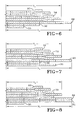
- FIG 6 illustrates an additional embodiment similar to Figure 4 , except for the following differences.
- the belt structure 40 further includes a second zigzag belt structure 92 located radially outward of the first zigzag belt structure 70.
- the second zigzag belt structure 92 has a width less than the first zigzag belt structure 70.
- the zigzag belt structures 70, 92 have a width less than the width of the belt layer 60.
- Figure 7 illustrates an additional embodiment similar to Figure 6 , except for the following differences.
- Figure 7 illustrates two outer zigzag belt structures 70, 92 and three low angle belt layers 60, 50, 56.
- the belt layer 60 is the widest belt layer of the belt structure 40.
- the middle low angle belt layer 50 is the narrowest belt layer of the belt package 40.
- the radially innermost belt 56 has a width greater than the middle belt layer 50 and the radially outermost zigzag belt 92.
- FIG 8 illustrates yet another embodiment which is similar to the embodiment shown in Figure 6 , except for the following differences.
- the belt package 40 includes two radially outer zigzag belts 92, 70 and three low angle belts 55, 60, 61. Two of the low angle belts 60, 61 have the same width and are the widest belts of the belt package.
- One of the belts 55 is located radially inward and has the narrowest width in the range of 13% to 47 % of the rim width between the flanges.
- Figure 9 illustrates still another embodiment of the present invention.
- Figure 9 is similar to the embodiment shown in Figure 3 , except for the following differences.
- the embodiment of figure 9 includes two radially inner low angle belts 50, 60.
- Low angle belt 60 is the widest belt of the belt package.
- the present embodiment further includes two additional zigzag belt structures 68, 69 wherein both belt structures are located radially outward of the first zigzag belt structure 70.
- the belt structures 68, 69, 70 have decreasing belt widths so that the radially innermost belt is the widest belt, and the radially outermost belt is the narrowest.
- Figure 10 illustrates a variation of the embodiment of Figure 9 wherein a third low angle belt 51 is located radially inward of low angle belt 50 and has a width in the range of 13% to 47% of the rim width between the flanges.
- the cords are preferably continuously wound from one belt structure to the next.
- the cords of any of the above described carcass, spiral or zigzag belt layers described above may be nylon, nylon 6,6, aramid, or combinations thereof, including merged, hybrid, high energy constructions known to those skilled in the art.
- a suitable cord construction for the belt cords, carcass cords (or both) may comprise a composite of aramid and nylon, containing two cords of a polyamide (aramid) preferably with construction of 3300 dtex with a 6.7 twist, and one nylon or nylon 6/6 cord preferably having a construction of 1880 dtex, with a 4.5 twist.
- the overall merged cable twist is preferably 6.7.
- the composite cords may have an elongation at break greater than 11% and a tensile strength greater than 900 newtons.
- the original linear density may be greater than 8500 dtex. Elongation, break, linear density and tensile strength are determined from cord samples taken after being dipped but prior to vulcanization of the tire.
Landscapes
- Engineering & Computer Science (AREA)
- Mechanical Engineering (AREA)
- Tires In General (AREA)
Claims (15)
- Bandage pneumatique possédant une carcasse (22) et une structure de renforcement de ceinture (40), la structure de renforcement de ceinture (40) comprenant une première couche de ceinture (60) possédant des câblés arrangés en formant un angle de +/- 5 degrés ou moins par rapport au plan équatorial (EP) du bandage pneumatique (10) et au moins une structure de renforcement de ceinture en zigzag (70, 90, 92) située en position radiale à l'extérieur de la première couche de ceinture (60), la structure de renforcement de ceinture en zigzag (70, 90, 92) formant au moins deux couches de câblés, les câblés étant inclinés en formant des angles de +/- 5 à +/- 30 degrés par rapport au plan équatorial (EP) du bandage pneumatique (10) et s'étendant en alternance jusqu'à des endroits de retournement (44, 45) aux bords latéraux, la première couche de ceinture (60) étant plus large que la structure de renforcement de ceinture en zigzag (70, 90, 92), et dans lequel le bandage pneumatique comprend en outre au moins une deuxième couche de ceinture (50) possédant des câblés arrangés en formant un angle de +/- 5 degrés ou moins par rapport au plan équatorial (EP) du bandage pneumatique (10), caractérisé en ce que la deuxième couche de ceinture (50) est plus étroite que la structure de renforcement de ceinture en zigzag (70, 90, 92) et/ou en ce que la deuxième couche de ceinture (50) possède une largeur axiale inférieure à la largeur axiale de la première couche de ceinture (60).
- Bandage pneurnatique selon la revendication 1, dans lequel la deuxième couche de ceinture (50) est disposée en position radiale à l'intérieur de la structure de renforcernent de ceinture en zigzag (70, 90,92).
- Bandage pneumatique selon la revendication 1 ou 2, dans lequel la deuxième couche de ceinture (50) est disposée en position radiale à l'intérieur de la première couche de ceinture (60).
- Bandage pneumatique selon la revendication 1, dans lequel la deuxième couche de ceinture (50) est située entre la structure de renforcement de ceinture en zigzag (70, 90, 92) et la première couche de ceinture (60).
- Bandage pneumatique selon la revendication 1, dans lequel la deuxième couche de ceinture (50) est disposée en position radiale à l'extérieur de la première couche de ceinture (60).
- Bandage pneumatique selon au moins une des revendications précédentes, dans lequel la première et la deuxième couche de ceinture (60, 50) sont réalisées par enroulement hélicoïdal de bandes comprenant des câblés.
- Bandage pneumatique selon au moins une des revendications précédentes, dans lequel le rapport de la largeur (Wz) de la structure de renforcement de ceinture en zigzag (70, 90, 92) à la largeur (Ws) de la couche de ceinture la plus large (50, 60) se situe dans la plage de:

- Bandage pneumatique selon au moins une des revendications précédentes, dans lequel une ou plusieurs des couches de ceinture (50, 60) comprennent des câblés constitués d'un mélange de nylon et d'aramide.
- Bandage pneumatique selon au moins une des revendications précédentes, dans lequel une ou plusieurs des couches de ceinture (50, 60) comprennent des câblés constitués d'aramide.
- Bandage pneumatique selon au moins une des revendications précédentes, comprenant en outre une troisième couche de ceinture (55) disposée en position radiale à l'intérieur desdites première et deuxième couches de ceintures (60, 50).
- Bandage pneumatique selon la revendication 10, dans lequel la troisième couche de ceinture (55) possède une largeur axiale inférieure à la largeur axiale de la première couche de ceinture (60) et/ou une largeur axiale inférieure à la largeur axiale de la deuxième couche de ceinture (50).
- Bandage pneumatique selon au moins une des revendications précédentes, dans lequel la structure de renforcement de ceinture (40) comprend deux couches de ceinture en spirale (50, 55) internes en direction radiale, deux couches de ceinture en spirale (60) externes en direction radiale et deux structures de renforcement de ceintures en zigzag (70, 90, 92).
- Bandage pneumatique selon au moins une des revendications précédentes, dans lequel au moins une des couches de ceintures (50, 55, 60) possède des câblés possédant un pourcentage d'allongement à la rupture supérieur à 11 % et/ou une résistance à la rupture supérieure à 900 N, avec une densité linéaire supérieure à 8500 dtex.
- Bandage pneumatique selon au moins une des revendications précédentes, dans lequel la carcasse comprend du nylon.
- Bandage pneumatique selon au moins une des revendications précédentes, dans lequel le bandage pneumatique est un bandage pneumatique pour aéroplane.
Applications Claiming Priority (2)
| Application Number | Priority Date | Filing Date | Title |
|---|---|---|---|
| US35385410P | 2010-06-11 | 2010-06-11 | |
| US13/085,007 US9346321B2 (en) | 2010-06-11 | 2011-04-12 | Reduced weight aircraft tire |
Publications (2)
| Publication Number | Publication Date |
|---|---|
| EP2394822A1 EP2394822A1 (fr) | 2011-12-14 |
| EP2394822B1 true EP2394822B1 (fr) | 2013-05-29 |
Family
ID=45101333
Family Applications (1)
| Application Number | Title | Priority Date | Filing Date |
|---|---|---|---|
| EP11168675.4A Active EP2394822B1 (fr) | 2010-06-11 | 2011-06-03 | Pneu comportant une structure de renfort de sommet en zigzag, en particulier un pneu d'avion à poids réduit |
Country Status (5)
| Country | Link |
|---|---|
| US (1) | US9346321B2 (fr) |
| EP (1) | EP2394822B1 (fr) |
| JP (1) | JP2012001206A (fr) |
| KR (1) | KR101770831B1 (fr) |
| CN (1) | CN102275466B (fr) |
Families Citing this family (13)
| Publication number | Priority date | Publication date | Assignee | Title |
|---|---|---|---|---|
| US20120312440A1 (en) * | 2011-06-13 | 2012-12-13 | Kiyoshi Ueyoko | Reduced weight aircraft tire |
| US9272577B2 (en) * | 2011-06-13 | 2016-03-01 | The Goodyear Tire & Rubber Company | Aircraft radial tire |
| US11827064B2 (en) | 2015-08-31 | 2023-11-28 | The Goodyear Tire & Rubber Company | Reduced weight aircraft tire |
| US10723177B2 (en) * | 2015-08-31 | 2020-07-28 | The Goodyear Tire & Rubber Company | Reduced weight aircraft tire |
| US20180056724A1 (en) * | 2016-08-31 | 2018-03-01 | The Goodyear Tire & Rubber Company | Reduced weight aircraft tire |
| DE102017201631A1 (de) | 2017-02-01 | 2018-08-02 | Continental Reifen Deutschland Gmbh | Polyamid-Kord zur Verwendung als Karkass-Festigkeitsträger, Fahrzeugluftreifen umfassend einen oder mehrere Polyamid-Korde sowie ein Verfahren zur Herstellung eines oder mehrerer Polyamid-Kord, ein Verfahren zur Herstellung einer gummierten Verstärkungslage und ein Verfahren zur Herstellung eines Fahrzeugluftreifens |
| JP7129900B2 (ja) * | 2018-12-21 | 2022-09-02 | 株式会社ブリヂストン | 航空機用空気入りタイヤ |
| JP7133461B2 (ja) | 2018-12-21 | 2022-09-08 | 株式会社ブリヂストン | 航空機用空気入りタイヤ |
| JP2021079943A (ja) * | 2019-11-19 | 2021-05-27 | ザ・グッドイヤー・タイヤ・アンド・ラバー・カンパニー | 軽量化された航空機用タイヤ |
| CN111506964B (zh) * | 2020-04-13 | 2023-07-28 | 中策橡胶集团股份有限公司 | 带束设计优化的轮胎结构 |
| US20220185019A1 (en) * | 2020-12-16 | 2022-06-16 | The Goodyear Tire & Rubber Company | Tire with protective belt structure |
| CN114228404A (zh) * | 2021-12-03 | 2022-03-25 | 泰凯英(青岛)专用轮胎技术研究开发有限公司 | 重载用途的低断面轮胎带束环及其制作方法和应用 |
| US20240157734A1 (en) * | 2022-11-15 | 2024-05-16 | The Goodyear Tire & Rubber Company | Aircraft radial tire |
Family Cites Families (16)
| Publication number | Priority date | Publication date | Assignee | Title |
|---|---|---|---|---|
| US4201260A (en) * | 1976-05-07 | 1980-05-06 | Uniroyal, Inc. | Method for making a radial ply tire in a single building stage |
| US4155394A (en) | 1977-08-29 | 1979-05-22 | The Goodyear Tire & Rubber Company | Tire cord composite and pneumatic tire |
| US4893665A (en) | 1988-02-17 | 1990-01-16 | The Goodyear Tire & Rubber Company | Cables for reinforcing deformable articles and articles reinforced by said cables |
| JPH0370603A (ja) * | 1989-08-10 | 1991-03-26 | Bridgestone Corp | 空気入りラジアルタイヤ |
| JP3126516B2 (ja) * | 1991-10-29 | 2001-01-22 | 株式会社ブリヂストン | 航空機用ラジアルタイヤ |
| FR2719257B1 (fr) * | 1994-04-28 | 1996-07-19 | Dunlop Sa | Pneumatique radial renforcé pour poids lourd. |
| JP3198077B2 (ja) * | 1997-06-27 | 2001-08-13 | 住友ゴム工業株式会社 | 空気入りタイヤ |
| WO2002074560A1 (fr) * | 2001-03-16 | 2002-09-26 | Bridgestone Corporation | Pneumatique |
| FR2823698B1 (fr) | 2001-04-19 | 2004-05-07 | Michelin Soc Tech | Armatures de pneumatique pour avion |
| JP4424989B2 (ja) | 2002-01-24 | 2010-03-03 | 株式会社ブリヂストン | 空気入りタイヤ、及びその製造方法 |
| US6571847B1 (en) | 2002-01-24 | 2003-06-03 | The Goodyear Tire & Rubber Company | Light weight alloy bead core |
| US6799618B2 (en) | 2002-12-18 | 2004-10-05 | The Goodyear Tire & Rubber Company | Pneumatic tire having an overlay reinforcement |
| US20040163748A1 (en) * | 2003-02-24 | 2004-08-26 | Kiyoshi Ueyoko | Tire having a composite belt structure |
| JP4627664B2 (ja) * | 2005-02-15 | 2011-02-09 | 株式会社ブリヂストン | 空気入りラジアルタイヤ |
| US20080105352A1 (en) * | 2006-11-03 | 2008-05-08 | Kiyoshi Ueyoko | Reduced weight aircraft tire |
| JP2009196548A (ja) * | 2008-02-22 | 2009-09-03 | Bridgestone Corp | 空気入りタイヤ |
-
2011
- 2011-04-12 US US13/085,007 patent/US9346321B2/en active Active
- 2011-06-03 EP EP11168675.4A patent/EP2394822B1/fr active Active
- 2011-06-09 KR KR1020110055679A patent/KR101770831B1/ko active IP Right Grant
- 2011-06-10 CN CN201110155672.6A patent/CN102275466B/zh active Active
- 2011-06-10 JP JP2011130298A patent/JP2012001206A/ja active Pending
Also Published As
| Publication number | Publication date |
|---|---|
| US9346321B2 (en) | 2016-05-24 |
| KR101770831B1 (ko) | 2017-08-23 |
| JP2012001206A (ja) | 2012-01-05 |
| US20110303336A1 (en) | 2011-12-15 |
| KR20110135817A (ko) | 2011-12-19 |
| CN102275466A (zh) | 2011-12-14 |
| CN102275466B (zh) | 2015-06-03 |
| EP2394822A1 (fr) | 2011-12-14 |
Similar Documents
| Publication | Publication Date | Title |
|---|---|---|
| EP2394822B1 (fr) | Pneu comportant une structure de renfort de sommet en zigzag, en particulier un pneu d'avion à poids réduit | |
| EP2420396B1 (fr) | Pneumatique | |
| US20080105352A1 (en) | Reduced weight aircraft tire | |
| US11186122B2 (en) | Reduced weight aircraft tire | |
| US20240051344A1 (en) | Reduced weight aircraft tire | |
| US20160200147A1 (en) | Reduced weight aircraft tire | |
| EP1449680B1 (fr) | Un pneumatique ayant une structure de ceinture composée | |
| EP2977229B1 (fr) | Pneu d'aéronef à poids réduit | |
| EP3290232B1 (fr) | Pneu ayant un faible poids et une grande résistance à la crevaison | |
| EP3825149B1 (fr) | Pneu d'aéronef à poids réduit | |
| US8967213B2 (en) | Aircraft tire | |
| EP2444259B1 (fr) | Pneu à poids réduit | |
| EP2444258A2 (fr) | Pneu à poids réduit | |
| US20120312440A1 (en) | Reduced weight aircraft tire | |
| US20210380229A1 (en) | Reduced weight aircraft tire | |
| US20210146727A1 (en) | Reduced weight aircraft tire | |
| US20210146726A1 (en) | Reduced weight aircraft tire | |
| GB2507199A (en) | Pneumatic tyre |
Legal Events
| Date | Code | Title | Description |
|---|---|---|---|
| AK | Designated contracting states |
Kind code of ref document: A1 Designated state(s): AL AT BE BG CH CY CZ DE DK EE ES FI FR GB GR HR HU IE IS IT LI LT LU LV MC MK MT NL NO PL PT RO RS SE SI SK SM TR |
|
| AX | Request for extension of the european patent |
Extension state: BA ME |
|
| PUAI | Public reference made under article 153(3) epc to a published international application that has entered the european phase |
Free format text: ORIGINAL CODE: 0009012 |
|
| 17P | Request for examination filed |
Effective date: 20120614 |
|
| GRAP | Despatch of communication of intention to grant a patent |
Free format text: ORIGINAL CODE: EPIDOSNIGR1 |
|
| GRAS | Grant fee paid |
Free format text: ORIGINAL CODE: EPIDOSNIGR3 |
|
| GRAA | (expected) grant |
Free format text: ORIGINAL CODE: 0009210 |
|
| AK | Designated contracting states |
Kind code of ref document: B1 Designated state(s): AL AT BE BG CH CY CZ DE DK EE ES FI FR GB GR HR HU IE IS IT LI LT LU LV MC MK MT NL NO PL PT RO RS SE SI SK SM TR |
|
| REG | Reference to a national code |
Ref country code: GB Ref legal event code: FG4D |
|
| REG | Reference to a national code |
Ref country code: CH Ref legal event code: EP |
|
| REG | Reference to a national code |
Ref country code: AT Ref legal event code: REF Ref document number: 614129 Country of ref document: AT Kind code of ref document: T Effective date: 20130615 |
|
| REG | Reference to a national code |
Ref country code: IE Ref legal event code: FG4D |
|
| REG | Reference to a national code |
Ref country code: DE Ref legal event code: R096 Ref document number: 602011001786 Country of ref document: DE Effective date: 20130801 |
|
| REG | Reference to a national code |
Ref country code: AT Ref legal event code: MK05 Ref document number: 614129 Country of ref document: AT Kind code of ref document: T Effective date: 20130529 |
|
| REG | Reference to a national code |
Ref country code: LT Ref legal event code: MG4D |
|
| PG25 | Lapsed in a contracting state [announced via postgrant information from national office to epo] |
Ref country code: PT Free format text: LAPSE BECAUSE OF FAILURE TO SUBMIT A TRANSLATION OF THE DESCRIPTION OR TO PAY THE FEE WITHIN THE PRESCRIBED TIME-LIMIT Effective date: 20130930 Ref country code: GR Free format text: LAPSE BECAUSE OF FAILURE TO SUBMIT A TRANSLATION OF THE DESCRIPTION OR TO PAY THE FEE WITHIN THE PRESCRIBED TIME-LIMIT Effective date: 20130830 Ref country code: LT Free format text: LAPSE BECAUSE OF FAILURE TO SUBMIT A TRANSLATION OF THE DESCRIPTION OR TO PAY THE FEE WITHIN THE PRESCRIBED TIME-LIMIT Effective date: 20130529 Ref country code: AT Free format text: LAPSE BECAUSE OF FAILURE TO SUBMIT A TRANSLATION OF THE DESCRIPTION OR TO PAY THE FEE WITHIN THE PRESCRIBED TIME-LIMIT Effective date: 20130529 Ref country code: IS Free format text: LAPSE BECAUSE OF FAILURE TO SUBMIT A TRANSLATION OF THE DESCRIPTION OR TO PAY THE FEE WITHIN THE PRESCRIBED TIME-LIMIT Effective date: 20130929 Ref country code: SE Free format text: LAPSE BECAUSE OF FAILURE TO SUBMIT A TRANSLATION OF THE DESCRIPTION OR TO PAY THE FEE WITHIN THE PRESCRIBED TIME-LIMIT Effective date: 20130529 Ref country code: FI Free format text: LAPSE BECAUSE OF FAILURE TO SUBMIT A TRANSLATION OF THE DESCRIPTION OR TO PAY THE FEE WITHIN THE PRESCRIBED TIME-LIMIT Effective date: 20130529 Ref country code: NO Free format text: LAPSE BECAUSE OF FAILURE TO SUBMIT A TRANSLATION OF THE DESCRIPTION OR TO PAY THE FEE WITHIN THE PRESCRIBED TIME-LIMIT Effective date: 20130829 Ref country code: SI Free format text: LAPSE BECAUSE OF FAILURE TO SUBMIT A TRANSLATION OF THE DESCRIPTION OR TO PAY THE FEE WITHIN THE PRESCRIBED TIME-LIMIT Effective date: 20130529 Ref country code: ES Free format text: LAPSE BECAUSE OF FAILURE TO SUBMIT A TRANSLATION OF THE DESCRIPTION OR TO PAY THE FEE WITHIN THE PRESCRIBED TIME-LIMIT Effective date: 20130909 |
|
| REG | Reference to a national code |
Ref country code: NL Ref legal event code: VDEP Effective date: 20130529 |
|
| PG25 | Lapsed in a contracting state [announced via postgrant information from national office to epo] |
Ref country code: BG Free format text: LAPSE BECAUSE OF FAILURE TO SUBMIT A TRANSLATION OF THE DESCRIPTION OR TO PAY THE FEE WITHIN THE PRESCRIBED TIME-LIMIT Effective date: 20130829 Ref country code: RS Free format text: LAPSE BECAUSE OF FAILURE TO SUBMIT A TRANSLATION OF THE DESCRIPTION OR TO PAY THE FEE WITHIN THE PRESCRIBED TIME-LIMIT Effective date: 20130529 Ref country code: PL Free format text: LAPSE BECAUSE OF FAILURE TO SUBMIT A TRANSLATION OF THE DESCRIPTION OR TO PAY THE FEE WITHIN THE PRESCRIBED TIME-LIMIT Effective date: 20130529 Ref country code: HR Free format text: LAPSE BECAUSE OF FAILURE TO SUBMIT A TRANSLATION OF THE DESCRIPTION OR TO PAY THE FEE WITHIN THE PRESCRIBED TIME-LIMIT Effective date: 20130529 |
|
| PG25 | Lapsed in a contracting state [announced via postgrant information from national office to epo] |
Ref country code: LV Free format text: LAPSE BECAUSE OF FAILURE TO SUBMIT A TRANSLATION OF THE DESCRIPTION OR TO PAY THE FEE WITHIN THE PRESCRIBED TIME-LIMIT Effective date: 20130529 |
|
| PG25 | Lapsed in a contracting state [announced via postgrant information from national office to epo] |
Ref country code: SK Free format text: LAPSE BECAUSE OF FAILURE TO SUBMIT A TRANSLATION OF THE DESCRIPTION OR TO PAY THE FEE WITHIN THE PRESCRIBED TIME-LIMIT Effective date: 20130529 Ref country code: DK Free format text: LAPSE BECAUSE OF FAILURE TO SUBMIT A TRANSLATION OF THE DESCRIPTION OR TO PAY THE FEE WITHIN THE PRESCRIBED TIME-LIMIT Effective date: 20130529 Ref country code: BE Free format text: LAPSE BECAUSE OF FAILURE TO SUBMIT A TRANSLATION OF THE DESCRIPTION OR TO PAY THE FEE WITHIN THE PRESCRIBED TIME-LIMIT Effective date: 20130529 Ref country code: EE Free format text: LAPSE BECAUSE OF FAILURE TO SUBMIT A TRANSLATION OF THE DESCRIPTION OR TO PAY THE FEE WITHIN THE PRESCRIBED TIME-LIMIT Effective date: 20130529 Ref country code: CZ Free format text: LAPSE BECAUSE OF FAILURE TO SUBMIT A TRANSLATION OF THE DESCRIPTION OR TO PAY THE FEE WITHIN THE PRESCRIBED TIME-LIMIT Effective date: 20130529 |
|
| PG25 | Lapsed in a contracting state [announced via postgrant information from national office to epo] |
Ref country code: MC Free format text: LAPSE BECAUSE OF FAILURE TO SUBMIT A TRANSLATION OF THE DESCRIPTION OR TO PAY THE FEE WITHIN THE PRESCRIBED TIME-LIMIT Effective date: 20130529 Ref country code: NL Free format text: LAPSE BECAUSE OF FAILURE TO SUBMIT A TRANSLATION OF THE DESCRIPTION OR TO PAY THE FEE WITHIN THE PRESCRIBED TIME-LIMIT Effective date: 20130529 Ref country code: RO Free format text: LAPSE BECAUSE OF FAILURE TO SUBMIT A TRANSLATION OF THE DESCRIPTION OR TO PAY THE FEE WITHIN THE PRESCRIBED TIME-LIMIT Effective date: 20130529 |
|
| REG | Reference to a national code |
Ref country code: IE Ref legal event code: MM4A |
|
| PLBE | No opposition filed within time limit |
Free format text: ORIGINAL CODE: 0009261 |
|
| STAA | Information on the status of an ep patent application or granted ep patent |
Free format text: STATUS: NO OPPOSITION FILED WITHIN TIME LIMIT |
|
| PG25 | Lapsed in a contracting state [announced via postgrant information from national office to epo] |
Ref country code: IE Free format text: LAPSE BECAUSE OF NON-PAYMENT OF DUE FEES Effective date: 20130603 |
|
| 26N | No opposition filed |
Effective date: 20140303 |
|
| REG | Reference to a national code |
Ref country code: DE Ref legal event code: R097 Ref document number: 602011001786 Country of ref document: DE Effective date: 20140303 |
|
| REG | Reference to a national code |
Ref country code: CH Ref legal event code: PL |
|
| PG25 | Lapsed in a contracting state [announced via postgrant information from national office to epo] |
Ref country code: MT Free format text: LAPSE BECAUSE OF FAILURE TO SUBMIT A TRANSLATION OF THE DESCRIPTION OR TO PAY THE FEE WITHIN THE PRESCRIBED TIME-LIMIT Effective date: 20130529 |
|
| PG25 | Lapsed in a contracting state [announced via postgrant information from national office to epo] |
Ref country code: LI Free format text: LAPSE BECAUSE OF NON-PAYMENT OF DUE FEES Effective date: 20140630 Ref country code: CH Free format text: LAPSE BECAUSE OF NON-PAYMENT OF DUE FEES Effective date: 20140630 |
|
| PG25 | Lapsed in a contracting state [announced via postgrant information from national office to epo] |
Ref country code: SM Free format text: LAPSE BECAUSE OF FAILURE TO SUBMIT A TRANSLATION OF THE DESCRIPTION OR TO PAY THE FEE WITHIN THE PRESCRIBED TIME-LIMIT Effective date: 20130529 |
|
| PG25 | Lapsed in a contracting state [announced via postgrant information from national office to epo] |
Ref country code: TR Free format text: LAPSE BECAUSE OF FAILURE TO SUBMIT A TRANSLATION OF THE DESCRIPTION OR TO PAY THE FEE WITHIN THE PRESCRIBED TIME-LIMIT Effective date: 20130529 Ref country code: CY Free format text: LAPSE BECAUSE OF FAILURE TO SUBMIT A TRANSLATION OF THE DESCRIPTION OR TO PAY THE FEE WITHIN THE PRESCRIBED TIME-LIMIT Effective date: 20130529 |
|
| PG25 | Lapsed in a contracting state [announced via postgrant information from national office to epo] |
Ref country code: MK Free format text: LAPSE BECAUSE OF FAILURE TO SUBMIT A TRANSLATION OF THE DESCRIPTION OR TO PAY THE FEE WITHIN THE PRESCRIBED TIME-LIMIT Effective date: 20130529 Ref country code: LU Free format text: LAPSE BECAUSE OF NON-PAYMENT OF DUE FEES Effective date: 20130603 Ref country code: HU Free format text: LAPSE BECAUSE OF FAILURE TO SUBMIT A TRANSLATION OF THE DESCRIPTION OR TO PAY THE FEE WITHIN THE PRESCRIBED TIME-LIMIT; INVALID AB INITIO Effective date: 20110603 |
|
| GBPC | Gb: european patent ceased through non-payment of renewal fee |
Effective date: 20150603 |
|
| PG25 | Lapsed in a contracting state [announced via postgrant information from national office to epo] |
Ref country code: GB Free format text: LAPSE BECAUSE OF NON-PAYMENT OF DUE FEES Effective date: 20150603 |
|
| REG | Reference to a national code |
Ref country code: FR Ref legal event code: PLFP Year of fee payment: 6 |
|
| REG | Reference to a national code |
Ref country code: FR Ref legal event code: PLFP Year of fee payment: 7 |
|
| REG | Reference to a national code |
Ref country code: FR Ref legal event code: PLFP Year of fee payment: 8 |
|
| PG25 | Lapsed in a contracting state [announced via postgrant information from national office to epo] |
Ref country code: AL Free format text: LAPSE BECAUSE OF FAILURE TO SUBMIT A TRANSLATION OF THE DESCRIPTION OR TO PAY THE FEE WITHIN THE PRESCRIBED TIME-LIMIT Effective date: 20130529 |
|
| PGFP | Annual fee paid to national office [announced via postgrant information from national office to epo] |
Ref country code: IT Payment date: 20210511 Year of fee payment: 11 |
|
| REG | Reference to a national code |
Ref country code: FR Ref legal event code: PLFP Year of fee payment: 13 |
|
| PG25 | Lapsed in a contracting state [announced via postgrant information from national office to epo] |
Ref country code: IT Free format text: LAPSE BECAUSE OF NON-PAYMENT OF DUE FEES Effective date: 20220603 |
|
| PGFP | Annual fee paid to national office [announced via postgrant information from national office to epo] |
Ref country code: FR Payment date: 20230411 Year of fee payment: 13 Ref country code: DE Payment date: 20230412 Year of fee payment: 13 |