EP2394801B1 - Messer - Google Patents
Messer Download PDFInfo
- Publication number
- EP2394801B1 EP2394801B1 EP11004822.0A EP11004822A EP2394801B1 EP 2394801 B1 EP2394801 B1 EP 2394801B1 EP 11004822 A EP11004822 A EP 11004822A EP 2394801 B1 EP2394801 B1 EP 2394801B1
- Authority
- EP
- European Patent Office
- Prior art keywords
- blade carrier
- knife
- cutting
- blade
- housing
- Prior art date
- Legal status (The legal status is an assumption and is not a legal conclusion. Google has not performed a legal analysis and makes no representation as to the accuracy of the status listed.)
- Active
Links
Images


Classifications
-
- B—PERFORMING OPERATIONS; TRANSPORTING
- B26—HAND CUTTING TOOLS; CUTTING; SEVERING
- B26B—HAND-HELD CUTTING TOOLS NOT OTHERWISE PROVIDED FOR
- B26B5/00—Hand knives with one or more detachable blades
- B26B5/001—Hand knives with one or more detachable blades with blades being slid out of handle immediately prior to use
- B26B5/003—Hand knives with one or more detachable blades with blades being slid out of handle immediately prior to use comprising retraction means for the blade or the blade holder
Definitions
- the invention relates to a knife according to the preamble of claim 1.
- Such a knife is known from the DE 197 23 279 ,
- the knife comprises a knife housing in which a blade carrier is movably mounted between a safety position and a cutting position.
- the blade In the safety position, the blade is inaccessible to the user of the knife in the housing.
- the blade In the cutting position, the blade protrudes from an opening of the housing.
- the blade carrier can be moved by means of an actuator from the safety position to a first cutting position. By a cutting force on the blade, the blade carrier is movable from the first cutting position to a second cutting position.
- the second cutting position differs from the first cutting position in that the blade carrier is moved back in the actuation position befindaji actuator in the safety position. In the first cutting position, however, the blade carrier can not retreat into the housing when the actuating device is actuated.
- a knife wherein a lever is connected by means of a joint fixed to the blade carrier and with the actuating device.
- the blade carrier By moving an actuator into an actuated position, the blade carrier can be moved from a safety position to a first cutting position.
- a support element attached to the lever In the first cutting position, a support element attached to the lever is supported on the housing.
- the support loses contact with the housing and the blade carrier can move back to the safety position, even if the actuator is arranged in the actuated position.
- the actuating device comprises a connecting device with at least one connecting element.
- the connecting device is connected to the blade carrier with a first joint and connected to an actuating element of the actuating device with a second joint.
- the actuator is movable between a home position and an actuated position. By moving the actuator from the home position to the actuated position, the blade carrier is moved from a safety position to a first cutting position.
- the at least one connecting element of the connecting device is e.g. arranged on the movement of the blade carrier in the first cutting position in a first position. In the first position, the first joint has e.g. a first distance to the second joint.
- the first layer is e.g. a stable location. Stable position means according to the invention that by means of the connecting means forces from the actuating element can be transmitted to the blade carrier, which load the blade carrier in a cutting position.
- the blade carrier is movable from the first cutting position to a second cutting position.
- the connecting device In the second cutting position, the connecting device is moved, for example, in an intermediate position, from which the connecting elements are displaceable in a second position.
- the blade carrier In the second position of the connecting elements, the blade carrier is arranged in the safety position when the actuating device is in the actuation position is located.
- the liner is an unstable situation, for example.
- Unstable position in the sense of the invention means that no forces can be transmitted from the actuating element via the connecting device to the blade carrier, which load the blade carrier into a cutting position.
- a second distance is formed between the first joint and the second joint.
- the first distance is e.g. so large that is moved in operating position of the actuator blade carrier in the cutting position.
- the second distance is e.g. such that, when the actuator is in the actuated position, the blade carrier is located in the safety position.
- the connecting device can be arranged, for example, in the first position when the blade carrier is in the first cutting position.
- the blade carrier moves from the first cutting position to the second cutting position, e.g. the connecting device moves from the first layer into the intermediate layer.
- the blade carrier is loaded by a restoring element in the safety position.
- the blade carrier may be e.g. move back to the safety position as soon as the cutting force no longer holds the blade carrier in the cutting position.
- the connection means moves e.g. in the second position.
- the connecting device may comprise a first connecting element and a second connecting element, wherein the first connecting element and the second connecting element are connected by means of a third articulation. If the first connecting element and the second connecting element are in the first position, the degree of freedom of the connecting elements can be limited so that the first and the second Joint have the first distance from each other.
- the connecting device may be movable in the movement from the first layer to the second layer or in the intermediate layer over a position in which the first joint, the second joint and the third joint are arranged on a straight line.
- the first and / or the second connecting element may be formed according to a further embodiment of a handlebar.
- the handlebar is e.g. rod-shaped.
- the first connecting element and the second connecting element can be arranged very close to one another in the first position and be widely spaced from one another in the second position.
- an obtuse angle may be formed in the first cutting position between a center axis of the first connecting element and a center axis of the second connecting element, and a superposing angle may be formed in the second cutting position.
- the connecting means moves over a stretched position in which the first, second and third joints lie on a straight line.
- the blade carrier is loaded by a restoring force in the safety position. Once the blade carrier is no longer held by the actuator in the cutting position, it gives way to the safety position due to the restoring force. This may be the case, for example, when, after reaching the second cutting position of the blade carrier, the connecting device has been moved into the second position, in which a return movement of the blade carrier is possible when the actuating device is actuated.
- the actuating device is loaded by a restoring force in the basic position. Once the actuator is no longer actuated by the user, it automatically moves to the home position. With the actuator movement associated elements that do not belong to the actuator may also be charged in a certain position due to the restoring force.
- At least one connecting element is associated with a multi-armed lever with at least one first lever arm and a second lever arm.
- the first lever arm can form the first connecting element.
- the second lever arm may e.g. form a control over which the lever is loaded in a certain position or moved to a certain position.
- the blade carrier comprises first control means, which form a first control surface, wherein the first control surface cooperates with a second control surface, which is associated with the connecting device.
- first control surface can cooperate with the second control surface in such a way that the connection device is moved into a specific position.
- the first control surface may cooperate with the second control surface such that the connecting device is moved from the first layer into the intermediate layer.
- the blade carrier is mounted on the housing by means of a bearing device, wherein the blade carrier is rotatory and translationally movable by means of the bearing device. Due to the rotational and translational storage of the Blade carrier perform a complex movement, which has both rotational and translational motion elements.
- the blade carrier can, for example, perform a purely translatory movement. For example, in the movement from the first cutting position to the second cutting position, the movement of the blade carrier is a purely rotational.
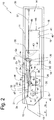
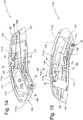
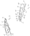
- a knife as a whole is designated by the reference numeral 10 in the figures.
- Same reference numerals in the different figures designate also with addition or omission of additions, such as small letters, appropriate parts.
- the knife 10 has a housing 11. In the housing 11, a receiving space 14 is formed.
- the knife 10 comprises a blade carrier 12 to which a blade 13 in a manner not shown releasably fastened.
- the blade carrier 12 is on the blade housing between in the Fig. 1 . 4 and 5 shown safety positions in which the blade 13 is inaccessible to a user in the receiving space 14 of the housing 11 is withdrawn and in the Fig. 2 and 3 shown cutting positions in which the blade 13 protrudes from an opening 15 of the housing 11.
- the mounting of the blade carrier 12 allows a translational movement relative to the housing 11 in the direction x1, x2 and a rotational movement in the direction u1, u2. The translational movement and the rotational movement of the blade carrier 12 are limited.
- a stub axle 20 is fixed, which is mounted in a groove 21 of the housing 11 about an axis a1 pivotally and translationally in the direction x1 and x2 movable.
- the housing 11 and the blade carrier 12 form a joint G1.
- the blade carrier 12 further comprises an extension 22, at the free end portion 23, a roller 24 is rotatably mounted.
- the blade carrier 12 can be moved by means of an actuator 16 between the safety position and the cutting position.
- the actuating device 16 comprises a connecting device 17 and an actuating element 19 which can be actuated by means of a handle, not shown.
- the handle can eg by a slider or a pivotable to the housing 11 between the lever in Fig. 1 shown basic position and in the Fig. 2 to 4 shown operating position to be moved.
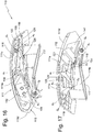
- the blade carrier 12 comprises a fastening region 25.
- the blade carrier 12 forms a pivot joint on the fastening region 25 G 2 with a first link 26 of the connecting device 17.
- the first link 26 is thus fixedly connected to the blade carrier 12 and pivotable about a pivot axis a 2 relative to the blade carrier 12 in the direction s1, s2.
- the first link 26 is fixedly connected to a joint G 3 with a second link 27 of a two-armed lever 28 of the connecting device 17.
- the second link 27 is pivotable relative to the first link 26 about a pivot axis a 3 .
- the two-armed lever 28 forms with the actuating element 19 a pivot joint G 4th
- the two-armed lever 28 is pivotally mounted about a pivot axis a 4 relative to the actuating element 19 in the direction w1, w2.
- a fastening eye 30 is formed, on which an end portion 31 of a spring element 32 designed as a tension spring is attached.
- An end region 33 of the spring element 32 is fastened to a fastening means 34 of the blade carrier 12.
- a holding means 35 is formed, to which an end portion 36 of a spring element 37 is attached.
- Another end portion 38 of the spring member 37 is fixed to a holding means 39.
- Bearing surfaces 40 of the actuating element 19 cooperate with guide surfaces 41 of the housing 11, which form a slotted guide for the actuating element 19.
- the guide surfaces 41 guide the actuator 19 in the movement between the home position and the operating position.
- On the housing 11, a rear stop 49 and a front stop 50 is provided for the actuating element 19.
- Fig. 1 is the actuator 19 of the actuator 16 in the basic position.
- the blade carrier 12 is arranged in a first safety position.
- a the center axis m 1 of the first link 26 connecting the pivot axes a 2 and a 3 is arranged at an obtuse angle ⁇ 1 to a central axis m 2 of the second link 27 connecting the pivot axes a 3 and a 4 .
- the pivot axis a2 of the joint G2 has a distance L1 to the pivot axis a4 of the joint G4.
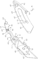
- the handle 17 can be against the spring force of the spring 37 of the user of the in Fig. 1 represented basic position in the in Fig. 2 shown actuating position to be moved.
- Upon movement of the handle 17 in the operating position of the blade carrier 12 is moved to a first cutting position (see Fig. 2 ).
- the angle ⁇ 1 between the first link 26 and the second link 27 remains unchanged.
- the distance L1 remains unchanged.
- the stub axle 20 of the blade carrier 12 is moved from an end region 42 of the groove 21 to an end region 43. While the stub axle 20 abuts in the basic position on a stop surface 44 of the groove 21, the stub axle 20 gets in the actuation position contact with a stop surface 45 of the groove 21st
- the rear end region of the extension 22 exerts a force on the first link 26 with the roller 24 and pivots the first link 26 about the pivot axis a 2 in the direction s 2 into the position according to FIG Fig. 3
- the central axes m 1 and m 2 form in the position according to Fig. 3 an obtuse angle ⁇ 2 .
- the blade 13 remains in the position according to Fig. 3 as long as the cutting force is at least as great as the spring force of the Spring element 32.
- the blade carrier 12 of the spring element 32 in the in Fig. 4 withdrawn shown safety position, wherein the arm 26 pivots about the pivot axis a 2 in the direction s 2 and the arm 27 about the pivot axis a 4 in the direction w 2 .
- the pivot axis a2 and the pivot axis a4 have a distance L2 at which the blade carrier 12 is in the second safety position when the actuating element 19 according to FIG Fig. 4 is arranged in the actuation position.
- the handle element 19 When the operating device 16 is no longer actuated by the user, the handle element 19 is moved back by the spring element 37 in the direction x 2 (see Fig. 5 ). During the movement of the handle element 19 in the direction x 2 , the link 27 pivots about the pivot axis a 4 in the direction w 1 and the link 26 about the pivot axis a 2 in the direction s 1 . The spring element 32 is tensioned. The blade carrier 12 also moves in the direction x 2 until the stub axle 20 bears against the stop surface 44 of the groove 21.
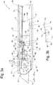
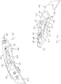
- a second embodiment of the knife is in the Fig. 6 to 21 represented and designated overall by the reference numeral 110.
- the knife comprises a housing 111, with a first housing shell 111 a and a second housing shell 111 b. Further, a third Housing shell 111c and a fourth housing shell 111d provided, which are fastened to the unit of the first housing shell 111 a and second housing shell 111 b.
- the fourth housing shell 111d is provided with an opening 115, which forms the blade outlet opening in the mounted state of the knife 110.
- a carriage 118 In a receiving space 114 of the housing 111, a carriage 118 is movably received. On the carriage 118, a blade carrier 112 is attached by means of a connecting device. The carriage 118 forms with a first link 119 of the connecting device, a first joint G5. By means of a second joint G6, the first link 119 is connected to a second link 120, which is also associated with the connecting device. The second link 120 forms with the blade carrier 112, a third joint G7.
- the carriage 118 includes according to Fig. 20 an upper sliding surface 123 which cooperates with a housing surface 171.
- a slot 125 is formed in the carriage 118.
- the elongated hole 125 has at one end region a shoulder 126 with a holding surface 127.
- a recess 128 is provided in the carriage 118.
- an actuating surface 129 is formed at an end portion of the carriage 118.
- a mounting hook 130 is formed on the carriage 118 and serves to attach a spring 121.
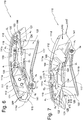
- a handle 117 comprises a strip 131 with a gripping surface 132.
- An extension 133 is formed on an end region of the strip 131.
- the extension 133 comprises a shoulder 134 with a holding surface 135 and an actuating surface 124.
- Another end region of the bar 131 is provided with a recess 136 for forming a pivot joint G8.
- the blade carrier 112 comprises a recess 137, which forms the third joint G7 with a pin 138 of the second link 120.
- a retaining seat 140 of the blade carrier 112 is used for releasably securing a blade 141.
- a flap 142 is pivotally mounted on the blade carrier 112, according to Fig. 18 is the blade 141 between a Surface 143 of the retaining seat 140 and a surface of the flap 142 is held.
- the flap 142 is pivotally attached to the blade carrier 112 about a pivot axis a9.
- a pin 138 of the second link 120 forms with the recess 137 of the blade carrier 112, the third joint G7 with a hinge axis a7. Eccentrically to the hinge axis a7 of the third joint G7, a fastening extension 139 is formed on the pin 138, to which a spring 122 can be fastened.
- a pin 145 of the second link 120 forms with a recess 146 of the first link 119, the second joint G6 with a hinge axis a6.
- a pin 147 is also formed, which forms with the recess 128 of the carriage 118, the first joint G5 with a pivot axis a5.
- the link 119 has a control surface 148, which is formed on a projection 149.
- the first housing shell 111 a comprises a pin 150 which has a first area 151 and a second area 152.
- the first region 151 passes through a recess 136 of the handle 117 and a recess 161 of the fourth housing shell 111 d.
- a nose 153 is integrally formed with a contact surface 154 which cooperates with the projection 149.
- a fixing pin 155 for fixing the spring 122 and a fixing pin 156 for fixing the spring 121 to the first housing shell 111 a are formed.
- the second housing shell 111 b is provided with a recess 157 which is penetrated in the mounted state of the knife 110 of the region 152 and the formation of the fourth joint G8 with a pivot axis a8 is used. Further, the housing shells 111a and 111b have a mounting structure 158 corresponding to a mounting structure on an inner side 159 of the third housing shell 111c to connect the third housing shell 111c to the first housing shell 111a and second housing shell 111b Fasten.
- the fourth housing shell 111d comprises a projection 160 with the recess 161.
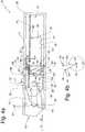
- the position of the blade carrier 112 relative to the carriage 118 is shown without housing 111 for clarity.
- the pin 147 of the first link 119 passes through the recess 128 of the carriage 118 and is pivotally mounted there.
- the pin 138 passes through the slot 125 and is guided in the slot 125.
- the pin 138 is pivotally mounted on the blade carrier 112.
- the blade carrier 112 can between a example in the FIGS. 20 and 21 shown primary position and one example in the FIGS. 22 and 23 shown secondary position to be moved.
- an imaginary first straight line 162 connecting the first pivot joint G5 and the second pivot joint G6 and an imaginary second straight line 163 connecting the second pivot joint G6 and the third pivot joint G7 form an angle ⁇ 3.
- the first straight line 162 and the second straight line 163 form an angle ⁇ 4.
- the carriage 118 is arranged in a rest position.
- the carriage 118 can be moved from the rest position to the operating position, which in the 8 and 9 is shown.
- the carriage 118 is moved back to the rest position by the first spring 121, whereby the handle 117 is moved in the direction t1 by the cooperating surfaces 124 and 129.
- the carriage 118 is in the rest position and the blade 141 is in the safety position arranged in the receiving space 114.
- the blade carrier 112 is located in the primary position to the carriage 118 and is biased by the spring 122 back to the rest position.
- An arm 164 of the second link 120 is supported on a surface 165 of the carriage 118.
- the carriage 118 When the handle 117 according to the 8 and 9 is actuated, the carriage 118 is in the operating position.
- the blade carrier 112 maintains the primary position to the carriage 118 unchanged, so that the blade 141 exits from a front opening 115 of the housing 111.
- the position of the blade carrier 112 according to the 8 and 9 is referred to as the first cutting position.
- the eccentric arrangement of the spring 122 on the attachment extension 139 in the first cutting position is not relevant. In the second cutting position, however, the lever arm is larger and loads the blade carrier 112 in the secondary position.
- the blade carrier 112 By a force acting through the cut on the blade 141, the blade carrier 112 is pivoted, wherein a pivot contour 170 of the blade carrier 112 cooperates with the housing surface 171 and forms a pivot point.
- a shoulder surface 172 of the second link 120 is brought into abutment with a holding surface 127 of the carriage 118 (see FIGS 10 and 11 ) to prevent unwanted movement of the blade carrier 112 to the safety position during the cutting operation.
- the first straight line 162 moves relative to the second straight line 163 beyond a dead center position (see FIGS 10 and 11 ). In this case, the angle change described above takes place between the first straight line 162 and the second straight line 163.
- This position of the blade carrier 112 is referred to as the second cutting position.
- the secondary position is in the FIGS. 14 and 15 shown.
- the blade 113 In the secondary position, the blade 113 is located in the safety position, although the handle 117 according to the FIGS. 14 and 15 operated and the carriage 118 is in the operating position. In the safety position, the blade 141 is arranged in the receiving space 114, so that the user can not injure himself on the blade 141.
- the handle 117 is moved indirectly from the carriage 118 to the unactuated position (see Figs FIGS. 16 and 17 ) emotional.
- the carriage 118 is moved back by the first spring 121 in the rest position, while the rearward movement of the blade carrier 112 is prevented by a stop 166, to which an abutment surface 167 of the blade carrier 112 according to the FIGS. 16 and 17 is applied.
- the contact surface 154 of a nose 153 formed on the housing 111 cooperates with a control surface 148 of a control cam 149 of the first link 119.
- a slide operable from outside the housing may be provided to move the slide 118 between the rest position and the actuated position.
- the blade carrier 112 is fixedly connected to the carriage 118 by means of the connecting device.
Landscapes
- Life Sciences & Earth Sciences (AREA)
- Forests & Forestry (AREA)
- Engineering & Computer Science (AREA)
- Mechanical Engineering (AREA)
- Knives (AREA)
Priority Applications (1)
| Application Number | Priority Date | Filing Date | Title |
|---|---|---|---|
| PL11004822T PL2394801T3 (pl) | 2010-06-14 | 2011-06-14 | Nóż |
Applications Claiming Priority (1)
| Application Number | Priority Date | Filing Date | Title |
|---|---|---|---|
| DE102010023680A DE102010023680A1 (de) | 2010-06-14 | 2010-06-14 | Messer |
Publications (2)
| Publication Number | Publication Date |
|---|---|
| EP2394801A1 EP2394801A1 (de) | 2011-12-14 |
| EP2394801B1 true EP2394801B1 (de) | 2017-03-01 |
Family
ID=44543900
Family Applications (1)
| Application Number | Title | Priority Date | Filing Date |
|---|---|---|---|
| EP11004822.0A Active EP2394801B1 (de) | 2010-06-14 | 2011-06-14 | Messer |
Country Status (5)
| Country | Link |
|---|---|
| US (1) | US8707566B2 (pl) |
| EP (1) | EP2394801B1 (pl) |
| DE (1) | DE102010023680A1 (pl) |
| ES (1) | ES2625471T3 (pl) |
| PL (1) | PL2394801T3 (pl) |
Families Citing this family (20)
| Publication number | Priority date | Publication date | Assignee | Title |
|---|---|---|---|---|
| US8595941B2 (en) * | 2010-10-29 | 2013-12-03 | Taylor Brands, Llc | Assisted-opening knife |
| DE102011007234B3 (de) * | 2011-04-12 | 2012-09-20 | Martor Kg | Sicherheits-Messer |
| US8776380B1 (en) * | 2011-04-25 | 2014-07-15 | Elwood Dean Quimby | Utility knife with retractable blade |
| CN202895248U (zh) * | 2012-03-23 | 2013-04-24 | 上海美瑞实业有限公司 | 安全裁切刀 |
| DE102013006599A1 (de) * | 2012-08-30 | 2014-04-03 | Martor Kg | Schneidvorrichtung |
| DE202013007112U1 (de) * | 2013-08-09 | 2014-11-13 | Martor Kg | Messer |
| DE102013014684A1 (de) * | 2013-09-05 | 2015-03-05 | Martor Kg | Messer |
| DE102014208473B4 (de) * | 2014-05-06 | 2019-06-19 | Martor Kg | Messer mit automatischer Klingenrückstellung |
| US10814505B2 (en) * | 2014-05-06 | 2020-10-27 | Martor Kg | Knife with automatic blade retraction |
| DE102015005768A1 (de) * | 2015-05-08 | 2016-11-10 | Martor Kg | Messer |
| US9808941B2 (en) * | 2016-01-15 | 2017-11-07 | Klever Kutter Llc | Safety utility knife assemblies, and components for use within safety utility knifes |
| DE102016008724A1 (de) * | 2016-07-21 | 2018-01-25 | Martor Kg | Messer |
| US11097434B2 (en) * | 2017-12-21 | 2021-08-24 | Mark Gordon Hooper | Utility knife |
| DE102018117203B4 (de) * | 2018-07-17 | 2024-02-01 | Martor Kg | Messer |
| US10589436B1 (en) * | 2019-07-09 | 2020-03-17 | Toughbuilt Industries, Inc. | Single-action convertible utility knife and scrapper |
| US11084178B2 (en) * | 2019-10-03 | 2021-08-10 | Industro International Co., Ltd. | Box cutter |
| DE102019131546B4 (de) * | 2019-11-21 | 2025-03-27 | Martor Kg | Messer |
| US11254020B2 (en) * | 2019-12-11 | 2022-02-22 | Tsang Wing WONG | Safety cutter |
| DE102021121232A1 (de) | 2021-08-16 | 2023-02-16 | Safety Products Holdings Gmbh | Messer |
| US20260001244A1 (en) * | 2023-12-22 | 2026-01-01 | Ningbo Xingwei Cutting-Tools Technology Co., Ltd. | Multi-functional knife |
Family Cites Families (8)
| Publication number | Priority date | Publication date | Assignee | Title |
|---|---|---|---|---|
| US4713885A (en) * | 1986-12-08 | 1987-12-22 | Ronald Keklak | Safe utility knife |
| US5303474A (en) * | 1992-11-30 | 1994-04-19 | Psi, Inc. | Safety utility knife |
| DE19723279C1 (de) | 1997-06-04 | 1998-04-23 | Beermann Kg Martor Argentax | Messer |
| US6813833B2 (en) * | 2002-01-16 | 2004-11-09 | Nottingham-Spirk Design Associates, Inc. | Utility knife |
| DE20210670U1 (de) * | 2002-07-10 | 2002-09-26 | Zeng, Min Zheng, Nantou | Messer mit einem auf Druck reagierenden Klingenvorschub |
| US20040237312A1 (en) * | 2003-05-22 | 2004-12-02 | Hector Hernandez | Knife with trigger actuator for retractable blade |
| ES2368529T3 (es) * | 2007-04-16 | 2011-11-18 | Adco Industries, A Subsidiary Of Dallco Marketing, Inc. | Corte de material rígido y semirígido. |
| DE102008019441A1 (de) | 2008-04-17 | 2009-10-22 | Martor Kg | Messer |
-
2010
- 2010-06-14 DE DE102010023680A patent/DE102010023680A1/de not_active Withdrawn
-
2011
- 2011-06-14 PL PL11004822T patent/PL2394801T3/pl unknown
- 2011-06-14 EP EP11004822.0A patent/EP2394801B1/de active Active
- 2011-06-14 US US13/159,599 patent/US8707566B2/en active Active
- 2011-06-14 ES ES11004822.0T patent/ES2625471T3/es active Active
Non-Patent Citations (1)
| Title |
|---|
| None * |
Also Published As
| Publication number | Publication date |
|---|---|
| US20110302787A1 (en) | 2011-12-15 |
| DE102010023680A1 (de) | 2011-12-15 |
| ES2625471T3 (es) | 2017-07-19 |
| EP2394801A1 (de) | 2011-12-14 |
| US8707566B2 (en) | 2014-04-29 |
| PL2394801T3 (pl) | 2017-08-31 |
Similar Documents
| Publication | Publication Date | Title |
|---|---|---|
| EP2394801B1 (de) | Messer | |
| EP2965879B1 (de) | Messer | |
| EP2203281B2 (de) | Messer | |
| EP2716420B1 (de) | Messer | |
| EP1934021B1 (de) | Messer | |
| EP2145651B1 (de) | Anschlagelement für eine Sicherungseinrichtung | |
| EP3041646B1 (de) | Messer | |
| DE102009048649A1 (de) | Mit einem Autositz verbindbarer Kinderwagen | |
| EP4290038B1 (de) | Scharnier zum lösbaren und verschwenkbaren verbinden eines flügels mit einem basisteil | |
| EP2272638B1 (de) | Messer | |
| EP3044071B1 (de) | Anordnung mit zumindest einem federkörper und zumindest einem separat ausgebildeten arretierteil | |
| DE4417491C2 (de) | Fanghaken zur lösbaren Verriegelung der mit dem Sitzteil eines Fahrzeugsitzes vorschwenkbar verbundenen Rückenlehne | |
| EP2656885B1 (de) | Vordereinheit für eine Gleitbrettbindung, insbesondere schwenkbare Vordereinheit mit Auslöseanordnung | |
| EP2163432A1 (de) | Hecklastträgerkupplung und Hecklastträger | |
| EP4289574B1 (de) | Messer | |
| EP3590760B1 (de) | Kopfstütze | |
| WO1995003761A1 (de) | Selbsttätig sperrendes gelenk, insbesondere orthesengelenk | |
| DE202007001394U1 (de) | Fahrzeugsitzstellhebel | |
| EP2314430B1 (de) | Messer | |
| DE19931953A1 (de) | Beschlag zur Lagerung eines Endes einer Latte eines Lattenrahmens | |
| DE102011014620A1 (de) | Schwenkklappenvorrichtung für Fahrzeuginnenräume | |
| EP2566668B1 (de) | Messer | |
| DE102021125710B3 (de) | Kapp- und Zugsäge | |
| EP2770154B1 (de) | Bündelungselement zum Bündeln von mindestens zwei Betätigungsschnüren für eine Verschattungsanlage | |
| WO2014032645A1 (de) | Schneidvorrichtung |
Legal Events
| Date | Code | Title | Description |
|---|---|---|---|
| AK | Designated contracting states |
Kind code of ref document: A1 Designated state(s): AL AT BE BG CH CY CZ DE DK EE ES FI FR GB GR HR HU IE IS IT LI LT LU LV MC MK MT NL NO PL PT RO RS SE SI SK SM TR |
|
| AX | Request for extension of the european patent |
Extension state: BA ME |
|
| PUAI | Public reference made under article 153(3) epc to a published international application that has entered the european phase |
Free format text: ORIGINAL CODE: 0009012 |
|
| 17P | Request for examination filed |
Effective date: 20120613 |
|
| GRAP | Despatch of communication of intention to grant a patent |
Free format text: ORIGINAL CODE: EPIDOSNIGR1 |
|
| INTG | Intention to grant announced |
Effective date: 20161010 |
|
| GRAS | Grant fee paid |
Free format text: ORIGINAL CODE: EPIDOSNIGR3 |
|
| GRAA | (expected) grant |
Free format text: ORIGINAL CODE: 0009210 |
|
| AK | Designated contracting states |
Kind code of ref document: B1 Designated state(s): AL AT BE BG CH CY CZ DE DK EE ES FI FR GB GR HR HU IE IS IT LI LT LU LV MC MK MT NL NO PL PT RO RS SE SI SK SM TR |
|
| REG | Reference to a national code |
Ref country code: GB Ref legal event code: FG4D Free format text: NOT ENGLISH |
|
| REG | Reference to a national code |
Ref country code: CH Ref legal event code: EP Ref country code: AT Ref legal event code: REF Ref document number: 870732 Country of ref document: AT Kind code of ref document: T Effective date: 20170315 |
|
| REG | Reference to a national code |
Ref country code: IE Ref legal event code: FG4D Free format text: LANGUAGE OF EP DOCUMENT: GERMAN |
|
| REG | Reference to a national code |
Ref country code: DE Ref legal event code: R096 Ref document number: 502011011693 Country of ref document: DE |
|
| REG | Reference to a national code |
Ref country code: CH Ref legal event code: NV Representative=s name: MOINAS AND SAVOYE SARL, CH |
|
| REG | Reference to a national code |
Ref country code: NL Ref legal event code: FP |
|
| REG | Reference to a national code |
Ref country code: FR Ref legal event code: PLFP Year of fee payment: 7 |
|
| REG | Reference to a national code |
Ref country code: LT Ref legal event code: MG4D |
|
| REG | Reference to a national code |
Ref country code: ES Ref legal event code: FG2A Ref document number: 2625471 Country of ref document: ES Kind code of ref document: T3 Effective date: 20170719 |
|
| PG25 | Lapsed in a contracting state [announced via postgrant information from national office to epo] |
Ref country code: LT Free format text: LAPSE BECAUSE OF FAILURE TO SUBMIT A TRANSLATION OF THE DESCRIPTION OR TO PAY THE FEE WITHIN THE PRESCRIBED TIME-LIMIT Effective date: 20170301 Ref country code: HR Free format text: LAPSE BECAUSE OF FAILURE TO SUBMIT A TRANSLATION OF THE DESCRIPTION OR TO PAY THE FEE WITHIN THE PRESCRIBED TIME-LIMIT Effective date: 20170301 Ref country code: NO Free format text: LAPSE BECAUSE OF FAILURE TO SUBMIT A TRANSLATION OF THE DESCRIPTION OR TO PAY THE FEE WITHIN THE PRESCRIBED TIME-LIMIT Effective date: 20170601 Ref country code: FI Free format text: LAPSE BECAUSE OF FAILURE TO SUBMIT A TRANSLATION OF THE DESCRIPTION OR TO PAY THE FEE WITHIN THE PRESCRIBED TIME-LIMIT Effective date: 20170301 Ref country code: GR Free format text: LAPSE BECAUSE OF FAILURE TO SUBMIT A TRANSLATION OF THE DESCRIPTION OR TO PAY THE FEE WITHIN THE PRESCRIBED TIME-LIMIT Effective date: 20170602 |
|
| PG25 | Lapsed in a contracting state [announced via postgrant information from national office to epo] |
Ref country code: SE Free format text: LAPSE BECAUSE OF FAILURE TO SUBMIT A TRANSLATION OF THE DESCRIPTION OR TO PAY THE FEE WITHIN THE PRESCRIBED TIME-LIMIT Effective date: 20170301 Ref country code: BG Free format text: LAPSE BECAUSE OF FAILURE TO SUBMIT A TRANSLATION OF THE DESCRIPTION OR TO PAY THE FEE WITHIN THE PRESCRIBED TIME-LIMIT Effective date: 20170601 Ref country code: RS Free format text: LAPSE BECAUSE OF FAILURE TO SUBMIT A TRANSLATION OF THE DESCRIPTION OR TO PAY THE FEE WITHIN THE PRESCRIBED TIME-LIMIT Effective date: 20170301 Ref country code: LV Free format text: LAPSE BECAUSE OF FAILURE TO SUBMIT A TRANSLATION OF THE DESCRIPTION OR TO PAY THE FEE WITHIN THE PRESCRIBED TIME-LIMIT Effective date: 20170301 |
|
| PG25 | Lapsed in a contracting state [announced via postgrant information from national office to epo] |
Ref country code: EE Free format text: LAPSE BECAUSE OF FAILURE TO SUBMIT A TRANSLATION OF THE DESCRIPTION OR TO PAY THE FEE WITHIN THE PRESCRIBED TIME-LIMIT Effective date: 20170301 Ref country code: IT Free format text: LAPSE BECAUSE OF FAILURE TO SUBMIT A TRANSLATION OF THE DESCRIPTION OR TO PAY THE FEE WITHIN THE PRESCRIBED TIME-LIMIT Effective date: 20170301 Ref country code: SK Free format text: LAPSE BECAUSE OF FAILURE TO SUBMIT A TRANSLATION OF THE DESCRIPTION OR TO PAY THE FEE WITHIN THE PRESCRIBED TIME-LIMIT Effective date: 20170301 Ref country code: RO Free format text: LAPSE BECAUSE OF FAILURE TO SUBMIT A TRANSLATION OF THE DESCRIPTION OR TO PAY THE FEE WITHIN THE PRESCRIBED TIME-LIMIT Effective date: 20170301 Ref country code: CZ Free format text: LAPSE BECAUSE OF FAILURE TO SUBMIT A TRANSLATION OF THE DESCRIPTION OR TO PAY THE FEE WITHIN THE PRESCRIBED TIME-LIMIT Effective date: 20170301 |
|
| PG25 | Lapsed in a contracting state [announced via postgrant information from national office to epo] |
Ref country code: PT Free format text: LAPSE BECAUSE OF FAILURE TO SUBMIT A TRANSLATION OF THE DESCRIPTION OR TO PAY THE FEE WITHIN THE PRESCRIBED TIME-LIMIT Effective date: 20170703 Ref country code: SM Free format text: LAPSE BECAUSE OF FAILURE TO SUBMIT A TRANSLATION OF THE DESCRIPTION OR TO PAY THE FEE WITHIN THE PRESCRIBED TIME-LIMIT Effective date: 20170301 Ref country code: IS Free format text: LAPSE BECAUSE OF FAILURE TO SUBMIT A TRANSLATION OF THE DESCRIPTION OR TO PAY THE FEE WITHIN THE PRESCRIBED TIME-LIMIT Effective date: 20170701 |
|
| REG | Reference to a national code |
Ref country code: DE Ref legal event code: R097 Ref document number: 502011011693 Country of ref document: DE |
|
| PLBE | No opposition filed within time limit |
Free format text: ORIGINAL CODE: 0009261 |
|
| STAA | Information on the status of an ep patent application or granted ep patent |
Free format text: STATUS: NO OPPOSITION FILED WITHIN TIME LIMIT |
|
| PG25 | Lapsed in a contracting state [announced via postgrant information from national office to epo] |
Ref country code: MC Free format text: LAPSE BECAUSE OF FAILURE TO SUBMIT A TRANSLATION OF THE DESCRIPTION OR TO PAY THE FEE WITHIN THE PRESCRIBED TIME-LIMIT Effective date: 20170301 Ref country code: DK Free format text: LAPSE BECAUSE OF FAILURE TO SUBMIT A TRANSLATION OF THE DESCRIPTION OR TO PAY THE FEE WITHIN THE PRESCRIBED TIME-LIMIT Effective date: 20170301 |
|
| 26N | No opposition filed |
Effective date: 20171204 |
|
| PG25 | Lapsed in a contracting state [announced via postgrant information from national office to epo] |
Ref country code: SI Free format text: LAPSE BECAUSE OF FAILURE TO SUBMIT A TRANSLATION OF THE DESCRIPTION OR TO PAY THE FEE WITHIN THE PRESCRIBED TIME-LIMIT Effective date: 20170301 |
|
| REG | Reference to a national code |
Ref country code: IE Ref legal event code: MM4A |
|
| PG25 | Lapsed in a contracting state [announced via postgrant information from national office to epo] |
Ref country code: IE Free format text: LAPSE BECAUSE OF NON-PAYMENT OF DUE FEES Effective date: 20170614 Ref country code: LU Free format text: LAPSE BECAUSE OF NON-PAYMENT OF DUE FEES Effective date: 20170614 |
|
| REG | Reference to a national code |
Ref country code: FR Ref legal event code: PLFP Year of fee payment: 8 |
|
| PG25 | Lapsed in a contracting state [announced via postgrant information from national office to epo] |
Ref country code: MT Free format text: LAPSE BECAUSE OF FAILURE TO SUBMIT A TRANSLATION OF THE DESCRIPTION OR TO PAY THE FEE WITHIN THE PRESCRIBED TIME-LIMIT Effective date: 20170301 |
|
| PG25 | Lapsed in a contracting state [announced via postgrant information from national office to epo] |
Ref country code: HU Free format text: LAPSE BECAUSE OF FAILURE TO SUBMIT A TRANSLATION OF THE DESCRIPTION OR TO PAY THE FEE WITHIN THE PRESCRIBED TIME-LIMIT; INVALID AB INITIO Effective date: 20110614 |
|
| PGFP | Annual fee paid to national office [announced via postgrant information from national office to epo] |
Ref country code: PL Payment date: 20190507 Year of fee payment: 9 |
|
| PGFP | Annual fee paid to national office [announced via postgrant information from national office to epo] |
Ref country code: CH Payment date: 20190624 Year of fee payment: 9 |
|
| PG25 | Lapsed in a contracting state [announced via postgrant information from national office to epo] |
Ref country code: CY Free format text: LAPSE BECAUSE OF NON-PAYMENT OF DUE FEES Effective date: 20170301 |
|
| PGFP | Annual fee paid to national office [announced via postgrant information from national office to epo] |
Ref country code: AT Payment date: 20190618 Year of fee payment: 9 |
|
| PG25 | Lapsed in a contracting state [announced via postgrant information from national office to epo] |
Ref country code: MK Free format text: LAPSE BECAUSE OF FAILURE TO SUBMIT A TRANSLATION OF THE DESCRIPTION OR TO PAY THE FEE WITHIN THE PRESCRIBED TIME-LIMIT Effective date: 20170301 |
|
| PG25 | Lapsed in a contracting state [announced via postgrant information from national office to epo] |
Ref country code: TR Free format text: LAPSE BECAUSE OF FAILURE TO SUBMIT A TRANSLATION OF THE DESCRIPTION OR TO PAY THE FEE WITHIN THE PRESCRIBED TIME-LIMIT Effective date: 20170301 |
|
| PG25 | Lapsed in a contracting state [announced via postgrant information from national office to epo] |
Ref country code: AL Free format text: LAPSE BECAUSE OF FAILURE TO SUBMIT A TRANSLATION OF THE DESCRIPTION OR TO PAY THE FEE WITHIN THE PRESCRIBED TIME-LIMIT Effective date: 20170301 |
|
| REG | Reference to a national code |
Ref country code: CH Ref legal event code: PL |
|
| REG | Reference to a national code |
Ref country code: AT Ref legal event code: MM01 Ref document number: 870732 Country of ref document: AT Kind code of ref document: T Effective date: 20200614 |
|
| PG25 | Lapsed in a contracting state [announced via postgrant information from national office to epo] |
Ref country code: CH Free format text: LAPSE BECAUSE OF NON-PAYMENT OF DUE FEES Effective date: 20200630 Ref country code: LI Free format text: LAPSE BECAUSE OF NON-PAYMENT OF DUE FEES Effective date: 20200630 |
|
| PG25 | Lapsed in a contracting state [announced via postgrant information from national office to epo] |
Ref country code: AT Free format text: LAPSE BECAUSE OF NON-PAYMENT OF DUE FEES Effective date: 20200614 |
|
| PG25 | Lapsed in a contracting state [announced via postgrant information from national office to epo] |
Ref country code: PL Free format text: LAPSE BECAUSE OF NON-PAYMENT OF DUE FEES Effective date: 20200614 |
|
| PGFP | Annual fee paid to national office [announced via postgrant information from national office to epo] |
Ref country code: NL Payment date: 20230620 Year of fee payment: 13 |
|
| PGFP | Annual fee paid to national office [announced via postgrant information from national office to epo] |
Ref country code: BE Payment date: 20230619 Year of fee payment: 13 |
|
| PGFP | Annual fee paid to national office [announced via postgrant information from national office to epo] |
Ref country code: ES Payment date: 20230719 Year of fee payment: 13 |
|
| PGFP | Annual fee paid to national office [announced via postgrant information from national office to epo] |
Ref country code: GB Payment date: 20240620 Year of fee payment: 14 |
|
| PGFP | Annual fee paid to national office [announced via postgrant information from national office to epo] |
Ref country code: DE Payment date: 20240607 Year of fee payment: 14 |
|
| PGFP | Annual fee paid to national office [announced via postgrant information from national office to epo] |
Ref country code: FR Payment date: 20240621 Year of fee payment: 14 |
|
| REG | Reference to a national code |
Ref country code: NL Ref legal event code: MM Effective date: 20240701 |
|
| PG25 | Lapsed in a contracting state [announced via postgrant information from national office to epo] |
Ref country code: NL Free format text: LAPSE BECAUSE OF NON-PAYMENT OF DUE FEES Effective date: 20240701 |
|
| PG25 | Lapsed in a contracting state [announced via postgrant information from national office to epo] |
Ref country code: NL Free format text: LAPSE BECAUSE OF NON-PAYMENT OF DUE FEES Effective date: 20240701 |
|
| PG25 | Lapsed in a contracting state [announced via postgrant information from national office to epo] |
Ref country code: BE Free format text: LAPSE BECAUSE OF NON-PAYMENT OF DUE FEES Effective date: 20240630 |
|
| REG | Reference to a national code |
Ref country code: BE Ref legal event code: MM Effective date: 20240630 |
|
| REG | Reference to a national code |
Ref country code: ES Ref legal event code: FD2A Effective date: 20250730 |
|
| PG25 | Lapsed in a contracting state [announced via postgrant information from national office to epo] |
Ref country code: ES Free format text: LAPSE BECAUSE OF NON-PAYMENT OF DUE FEES Effective date: 20240615 |
|
| REG | Reference to a national code |
Ref country code: DE Ref legal event code: R119 Ref document number: 502011011693 Country of ref document: DE |
|
| GBPC | Gb: european patent ceased through non-payment of renewal fee |
Effective date: 20250614 |