EP2394539B1 - Bi-material capsule - Google Patents
Bi-material capsule Download PDFInfo
- Publication number
- EP2394539B1 EP2394539B1 EP10306432.5A EP10306432A EP2394539B1 EP 2394539 B1 EP2394539 B1 EP 2394539B1 EP 10306432 A EP10306432 A EP 10306432A EP 2394539 B1 EP2394539 B1 EP 2394539B1
- Authority
- EP
- European Patent Office
- Prior art keywords
- capsule
- side wall
- outer side
- plastic material
- annular
- Prior art date
- Legal status (The legal status is an assumption and is not a legal conclusion. Google has not performed a legal analysis and makes no representation as to the accuracy of the status listed.)
- Active
Links
- 239000002775 capsule Substances 0.000 title claims description 132
- 239000000463 material Substances 0.000 title claims description 49
- 238000000605 extraction Methods 0.000 claims description 49
- 239000000126 substance Substances 0.000 claims description 34
- 239000012528 membrane Substances 0.000 claims description 27
- 239000004033 plastic Substances 0.000 claims description 24
- 229920003023 plastic Polymers 0.000 claims description 24
- 239000007788 liquid Substances 0.000 claims description 18
- 230000002093 peripheral effect Effects 0.000 claims description 15
- IJGRMHOSHXDMSA-UHFFFAOYSA-N Atomic nitrogen Chemical compound N#N IJGRMHOSHXDMSA-UHFFFAOYSA-N 0.000 claims description 4
- 239000004952 Polyamide Substances 0.000 claims description 3
- 229920002647 polyamide Polymers 0.000 claims description 3
- 230000003014 reinforcing effect Effects 0.000 claims description 3
- 229910052757 nitrogen Inorganic materials 0.000 claims description 2
- 229920002635 polyurethane Polymers 0.000 claims description 2
- 239000004814 polyurethane Substances 0.000 claims description 2
- 239000012530 fluid Substances 0.000 description 15
- 230000000694 effects Effects 0.000 description 12
- 235000013361 beverage Nutrition 0.000 description 7
- 238000007789 sealing Methods 0.000 description 4
- 238000004519 manufacturing process Methods 0.000 description 3
- 238000004040 coloring Methods 0.000 description 2
- 230000006835 compression Effects 0.000 description 2
- 238000007906 compression Methods 0.000 description 2
- 238000002347 injection Methods 0.000 description 2
- 239000007924 injection Substances 0.000 description 2
- 230000005012 migration Effects 0.000 description 2
- 238000013508 migration Methods 0.000 description 2
- 230000003647 oxidation Effects 0.000 description 2
- 238000007254 oxidation reaction Methods 0.000 description 2
- 239000002985 plastic film Substances 0.000 description 2
- 229920006255 plastic film Polymers 0.000 description 2
- 238000002360 preparation method Methods 0.000 description 2
- 231100000701 toxic element Toxicity 0.000 description 2
- XLYOFNOQVPJJNP-UHFFFAOYSA-N water Substances O XLYOFNOQVPJJNP-UHFFFAOYSA-N 0.000 description 2
- 230000004323 axial length Effects 0.000 description 1
- 230000004888 barrier function Effects 0.000 description 1
- 230000009286 beneficial effect Effects 0.000 description 1
- 230000015556 catabolic process Effects 0.000 description 1
- 239000012141 concentrate Substances 0.000 description 1
- 238000006731 degradation reaction Methods 0.000 description 1
- 238000009792 diffusion process Methods 0.000 description 1
- 239000000839 emulsion Substances 0.000 description 1
- 235000013305 food Nutrition 0.000 description 1
- 238000007373 indentation Methods 0.000 description 1
- 239000011261 inert gas Substances 0.000 description 1
- 230000014759 maintenance of location Effects 0.000 description 1
- 239000002184 metal Substances 0.000 description 1
- 239000000049 pigment Substances 0.000 description 1
- 238000003825 pressing Methods 0.000 description 1
- 238000007665 sagging Methods 0.000 description 1
- 230000003313 weakening effect Effects 0.000 description 1
Images


Classifications
-
- A—HUMAN NECESSITIES
- A47—FURNITURE; DOMESTIC ARTICLES OR APPLIANCES; COFFEE MILLS; SPICE MILLS; SUCTION CLEANERS IN GENERAL
- A47J—KITCHEN EQUIPMENT; COFFEE MILLS; SPICE MILLS; APPARATUS FOR MAKING BEVERAGES
- A47J31/00—Apparatus for making beverages
- A47J31/24—Coffee-making apparatus in which hot water is passed through the filter under pressure, i.e. in which the coffee grounds are extracted under pressure
- A47J31/34—Coffee-making apparatus in which hot water is passed through the filter under pressure, i.e. in which the coffee grounds are extracted under pressure with hot water under liquid pressure
- A47J31/36—Coffee-making apparatus in which hot water is passed through the filter under pressure, i.e. in which the coffee grounds are extracted under pressure with hot water under liquid pressure with mechanical pressure-producing means
- A47J31/3604—Coffee-making apparatus in which hot water is passed through the filter under pressure, i.e. in which the coffee grounds are extracted under pressure with hot water under liquid pressure with mechanical pressure-producing means with a mechanism arranged to move the brewing chamber between loading, infusing and ejecting stations
- A47J31/3623—Cartridges being employed
-
- B—PERFORMING OPERATIONS; TRANSPORTING
- B65—CONVEYING; PACKING; STORING; HANDLING THIN OR FILAMENTARY MATERIAL
- B65D—CONTAINERS FOR STORAGE OR TRANSPORT OF ARTICLES OR MATERIALS, e.g. BAGS, BARRELS, BOTTLES, BOXES, CANS, CARTONS, CRATES, DRUMS, JARS, TANKS, HOPPERS, FORWARDING CONTAINERS; ACCESSORIES, CLOSURES, OR FITTINGS THEREFOR; PACKAGING ELEMENTS; PACKAGES
- B65D85/00—Containers, packaging elements or packages, specially adapted for particular articles or materials
- B65D85/70—Containers, packaging elements or packages, specially adapted for particular articles or materials for materials not otherwise provided for
- B65D85/804—Disposable containers or packages with contents which are mixed, infused or dissolved in situ, i.e. without having been previously removed from the package
- B65D85/8043—Packages adapted to allow liquid to pass through the contents
- B65D85/8049—Details of the inlet
-
- B—PERFORMING OPERATIONS; TRANSPORTING
- B65—CONVEYING; PACKING; STORING; HANDLING THIN OR FILAMENTARY MATERIAL
- B65D—CONTAINERS FOR STORAGE OR TRANSPORT OF ARTICLES OR MATERIALS, e.g. BAGS, BARRELS, BOTTLES, BOXES, CANS, CARTONS, CRATES, DRUMS, JARS, TANKS, HOPPERS, FORWARDING CONTAINERS; ACCESSORIES, CLOSURES, OR FITTINGS THEREFOR; PACKAGING ELEMENTS; PACKAGES
- B65D85/00—Containers, packaging elements or packages, specially adapted for particular articles or materials
- B65D85/70—Containers, packaging elements or packages, specially adapted for particular articles or materials for materials not otherwise provided for
- B65D85/804—Disposable containers or packages with contents which are mixed, infused or dissolved in situ, i.e. without having been previously removed from the package
- B65D85/8043—Packages adapted to allow liquid to pass through the contents
- B65D85/8061—Filters
Definitions
- the present invention relates to a capsule for the extraction of a drink under pressure according to the preamble of claim 1.
- FR 2,373,999 discloses such a capsule for use in a beverage extraction device to produce a beverage such as coffee.
- An object of the invention is to provide a reduced cost capsule.
- Other objects of the invention are to propose a capsule made of a material which is inert with respect to the substance and bearing a distinctive mark making it possible to easily identify the substance contained in the chamber, to propose a capsule compatible with numerous beverage extraction devices, and provide a capsule to limit the risk of sagging while allowing the extraction of a drink.
- the subject of the invention is a capsule according to claim 1.
- said capsule comprises one or more of the features of claims 2 to 14.
- the subject of the invention is also, in a second aspect, a system comprising a capsule according to the first aspect of the invention, and an extraction device comprising a housing intended to receive the capsule, a support and a delivery duct. extraction liquid.
- the capsule 1 according to the first embodiment not according to the invention, represented on the Figures 1 to 3 , comprises a hollow body 4 and an outlet cap 6 defining together an inner chamber 8 containing a substance (not shown) for the preparation of a beverage.
- the body 4 has a general cup shape and comprises a side wall 10, a bottom 12 closing a closed rear end 20 of the body 4, and an annular flange 16 surrounding an open front end 22 of the body 4.
- the body 4 is made in one piece.
- the side wall 10, the bottom 12 and the annular flange 16 are integral.
- the body 4 is made of an airtight material and water, for example in a plastic material or derived from plastic, or metal.
- the side wall 10 extends from the bottom 12 along a longitudinal axis X to the front end 22 of the body 4.
- the side wall 10 includes an inner shoulder 14.
- the shoulder 14 extends in a radial plane and is oriented forward.
- the side wall 10 is substantially frustoconical of revolution about the longitudinal axis X.
- the side wall 10 comprises a rear section 18, relatively flexible, extending from the bottom 12 and a front section 19, relatively rigid, axially extending the rear section 18.
- the front section 19 has an axially increasing thickness, greater than that of the rear section 18.
- the bottom 12 has a peripheral region 23, extending radially inwards from the side wall 10, and a central region 24.
- the peripheral region 23 is rounded. It extends radially inwards and axially towards the rear from the side wall 10, and has a concavity turned towards the inside of the body 4.
- the central region 24 includes an annular rib 26 projecting axially inwardly of the body 4 from the peripheral region 23.
- the annular rib 26 defines an annular trench 28 open to the exterior of the body 4 rearwardly.
- the annular rib 26 defines a hollow central stud 30 protruding axially from the bottom of the annular trench 28 by defining a recess within the body 4.
- the central region 24 has at least one zone of weakness 32 designed to break under the effect of a fluid under pressure.
- the zones of least resistance 32 are provided, for example, in the form of zones of lesser thickness in the central region 24, defined for example by indentations formed in the central region 24.
- Areas of least resistance 32 are provided in walls of the annular rib 26 and / or on the central stud 30.
- the annular rib 26 comprises an outer tubular portion 36 extending axially inwardly from the peripheral region 23, an inner tubular portion 34 delimiting a lateral face of the central stud 30 and a bottom portion. 38 extending radially between the outer portion 36 and the inner portion 34 imparting to the annular rib 26 a cross section substantially shaped "U".
- zones of least resistance 32 are provided in the bottom portion 38 and in the central stud 30 in the form of areas of lesser thickness.
- the central region 24 is devoid of zone of least resistance 32 in the central block 30.
- the annular rib 26 has areas of lower resistance 32 in the outer portion 36 and / or the inner portion 34 .
- the outer portion 36 and the inner portion 34 converge conferring on the annular rib 26 a cross section substantially shaped "V".
- areas of least resistance 32 may be provided in the outer portion 36, the inner portion 34 and / or the central pin 30.
- the annular trench 28 has an outer edge 44 angular, preferably beveled, at the junction between the annular rib 26 and the peripheral region 23.
- the outer edge 44 defines the rear end 20 of the capsule 1.
- the central stud 30 is axially recessed towards the interior of the body 4 with respect to the outer edge 44.
- the peripheral region 23 has an extra thickness along the outer edge 44, so as to strengthen the outer edge 44.
- the peripheral region 23 has for example an increasing thickness from the side wall 10 to the outer edge 44.
- the internal shoulder 14 is annular and protrudes radially from the side wall 10 towards the inside of the body 4. It is recessed axially inwardly of the body 4 relative to the front end 22 of the body 4 and to the annular flange 16 .
- the cover 6 is fixed by its periphery to the internal shoulder 14 so that the cover 6 is disposed axially inwards towards the inside of the body 4 with respect to the front end 22 of the body 4.
- the distance of removal of the cap 6 relative to the front end 22 of the body 4 is greater than 1mm.
- the lid 6 closes the front end 22 of the body 4.
- the lid 6 comprises an outlet filter 49 capable of passing a fluid under pressure while retaining the substance contained in the chamber 8.
- the filter 49 is made of porous filter paper, woven plastic material or perforated plastic film.
- the lid 6 further comprises an air and water-tight membrane 50 doubling the filter 49.
- the membrane 50 has lines of weakness 52, so that the membrane 50 is able to tear under the sole the effect of the pressure of a liquid.
- the weakening lines 52 form a cross. Alternatively, they form a circle, circular arcs, or any other form adapted to allow optimal tearing of the membrane 50.
- the filter 49 is disposed between the chamber 8 and the membrane 50.
- the filter 49 and the membrane 50 are contiguous to each other.
- the filter 49 and the membrane 50 are for example in the form of a bilayer complex film.
- the annular flange 16 extends radially outwardly from the side wall 10.
- the annular flange 16 defines the front end 22 of the body 4.
- the flange 16 has a free marginal region 54. It does not support an attached sealing element or deformable sealing relief. As shown on the Figures 1 to 3 the annular flange 16 is substantially planar.
- the capsule 1 is intended to be disposed in an extraction device 350, represented on the Figures 4 and 5 .
- the extraction device 350 comprises a hollow receiving element 352, defining a housing 353 for receiving the capsule 1, and a support 354. It is adapted to be operated between an open configuration in which the receiving element 352 and the 354 are mutually spaced apart to introduce the capsule 1 into the receiving member 352, and a closed position, shown in FIG. Figure 5 in which the receiving member 352 and the holder 354 are mutually brought together to inject the extraction liquid into the capsule 1.
- the device 350 is shown in an intermediate configuration in which it is partially open, but not yet sufficiently open to allow the introduction of the capsule 1.
- the housing 353 has an inner side face 360, a housing bottom 370 and a conduit 372 for supplying extraction liquid opening on the housing bottom 370, substantially in the center and an opening 376 for introducing the capsule 1.
- the inner side face 360 is of revolution about a longitudinal axis Y. In the example shown, it is substantially frustoconical.
- the longitudinal axes X of the capsule 1 and Y of the housing 353 merge substantially.
- the receiving member 352 has an annular edge 380 surrounding the opening 376.
- the capsule 1 has a sufficient axial length so that, in the closed configuration of the extraction device 350, the capsule 1 is supported by its annular rim 16 against the support 354 and by its bottom 12 against the housing bottom 370 along a line closed annular contact contact 122, preferably defined on the peripheral region 23 along the outer edge 44 of the annular trench 28.
- the capsule 1 is advantageously adapted to deform elastically under the effect of an axial compression force F to ensure sufficient contact between the bottom 12 and the housing bottom 370.
- the capsule 1 is adapted so that, under the effect of the axial compression force F, at least one annular zone 130 of the bottom 12 and / or the side wall 10 of the capsule 1 expands radially outwardly so as to ensure an additional contact 128 with the lateral face 360 of the housing 353, following a closed annular contact line.
- the capsule 1 is first placed in the device 350 in open configuration, then the device 350 is operated to move in closed configuration.
- the capsule 1 is supported by its annular flange 16 against the support 354 and the receiving element 352 bears axially on the bottom 12 of the capsule 1, so that the contact 122 is created , and the body 4 is deformed as a whole so that the contact 128 is created with the receiving element 352 of the device 350.
- the extraction fluid is injected under pressure through the conduit 372.
- the zones of weakness 32 of the central region 24 of the bottom 12 rupture and the extraction fluid enters the capsule 1.
- the bottom reinforced by an annular rib enables the body of the capsule to be made of a relatively flexible, deformable material, without the bottom collapsing towards the inside of the capsule under the effect of the fluid pressure.
- the convexity of the bottom makes it possible to define a resilient and elastically deformable bottom, with a volume of the large chamber making it possible to load a larger quantity of substance into the capsule.
- the rib delimiting in the outer face an annular trench makes it possible to improve the injection of the extraction liquid into the capsule.
- the presence of an annular rim makes it possible to increase the stability of the capsule on the support of the extraction device.
- the capsule has a cup-shaped body whose bottom is airtight and watertight, the body being closed by a seal that is airtight and watertight.
- the tightness of the capsule keeps the substance safe from air and moisture.
- the cover has a membrane tearing under the effect of the pressurized fluid allowing appropriate opening of the cap from a determined pressure level, with a beneficial delay effect for a quality extraction.
- the operculum recessed axially towards the inside of the body avoids any interference with the support of the extraction device before the opening of the membrane, and thus allows controlled opening of the capsule.
- the membrane associated with a filter ensures extraction of the substance under satisfactory pressure conditions with effective retention of the substance inside the capsule.
- the operculum provided in the form of a complex film facilitates the manufacture of the capsule at low cost.
- Such a flange 16 makes it possible to guarantee and reinforce the contact 122 between the bottom 12 of the capsule 1 and the housing bottom 370 when the device 350 is closed, while being able to deform to allow the closure of the extraction device 350.
- the capsule 1000 according to the second embodiment, represented on the Figures 9 to 21 according to the invention, and includes, as visible on the Figures 9 and 10 , a hollow body 1004 and an outlet cap 1006 together defining an inner chamber 1008 containing a substance (not shown) for the preparation of a beverage.
- the body 1004 has a general cup shape and is airtight and watertight. It comprises an outer side wall 1010, a bottom 1012 closing a rear end 1020 of the body 1004, and an annular flange 1016 surrounding an open front end 1022 of the body 1004.
- the outer side wall 1010 and the bottom 1012 are made of material and are made of a first plastic material airtight and watertight.
- the first plastic material is chosen to be inert with respect to the substance contained in the capsule 1000.
- said first material is translucent and is not colored in the mass, so as to avoid the diffusion of the coloring. in the substance.
- the second plastic material is polyamide. Polyamide does not interfere with food products and is a very effective barrier to air and water.
- the annular flange 1016 is made of a second plastic material, different from the first plastic material.
- the second plastic material is preferably chosen to be a low cost material. Since it is not in contact with the substance, its properties vis-à-vis the substance do not take into account in the choice of the second material.
- the second plastic material is polyurethane, which is an inexpensive material.
- the first and second plastic materials are compatible materials, i.e. materials adapted to polymerize with each other.
- the second material is colored in the mass.
- the annular flanges 1016 of 1000 capsules containing different substances so as to easily distinguish a 1000 capsule containing a first substance of another 1000 capsule containing a second substance, different from the first.
- the outer side wall 1010 extends from the bottom 1012 along a longitudinal axis X to the front end 1022 of the body 1004.
- the outer side wall 1010 is substantially frustoconical of revolution about the longitudinal axis X. It is rigid. It has an inner surface 1010a, facing the chamber 1008, and an outer surface 1010b, opposite the inner surface 1010a.
- the bottom 1012 comprises a peripheral region 1023 and a central region 1024.
- Peripheral region 1023 is rigid. It is rounded and extends radially inwardly and axially rearwardly from the outer sidewall 1010, and has a concavity facing the interior of the body 1004. It thus extends from the outer sidewall 1010 to the rear end 1020 of the body 1004.
- the rear end 1020 is typically a closed line, for example a circle.
- Central region 1024 enters axially inward of chamber 1008 from the peripheral region.
- the central region 1024 thus defines in the bottom 1012 a recess 1028 outside the body 1004.
- the central region 1024 comprises an outer tubular portion 1036 extending axially inwardly of the chamber 1008 from the peripheral region 1023, a bottom portion 1038 extending radially inwardly from the inner end. of the outer potion 1036 and closing the recess 1028, and a central inner portion 1034 projecting outwardly from the bottom portion 1038.
- the inner portion 1034 defines a hollow central stud 1030 in the recess 1028.
- the latter thus has an annular shape.
- the outer portion 1036, the bottom portion 1038 and the inner portion 1034 define an annular rib 1026 in the central region 1024.
- the bottom portion 1038 comprises at least one zone 1032 of least resistance provided to break under the effect of a fluid under pressure.
- the or each zone of least resistance is provided to break at a pressure of the fluid under pressure of between 1 and 3 bar.
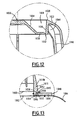
- the or each zone of least resistance 1032 is provided, for example, in the form of zones of lesser thickness, as shown in FIG. Figure 12 . As long as the or each zone of weakness 1032 is not broken, the bottom 1012, and by extension the entire body 1004, is impermeable to air and liquids.
- the zone of least resistance is defined at the periphery of the bottom portion 1038, at the junction between the bottom portion 1038 and the outer portion 1036.
- the zone of least resistance is in the form of a circular arc.
- the arc of the circle preferably extends over at least 270 °.
- the shape of the inner portion 1034 conditions the axial shear force generated by a pressurized liquid present in the recess 1028.
- the inner portion 1034 has a frustoconical shape, widening from the back to the front of the capsule 1000, and protruding outwardly.
- the inner portion 1034 extends in a radial plane. At a determined pressure of the fluid present in the recess 1028, a flat inner portion 1034 induces a higher shear force than an inner portion protruding outwardly.
- the body 1004 also comprises longitudinal ribs 1042 for stiffening the outer side wall 1010 and radial ribs 1044 for stiffening the bottom 1012.
- Each longitudinal rib 1042 extends longitudinally along the outer sidewall 1010, preferably, as shown, along the inner surface 1010a.
- the longitudinal ribs are adapted to promote the emulsion between the pressurized fluid and the substance contained in the chamber 1008.
- each longitudinal rib 1042 extends along the outer surface 1010b.
- Each radial rib 1044 extends radially between the outer portion 1036 and the peripheral region 1023.
- the radial ribs 1044 stiffen the bottom 12 and thus promote the generation of shear forces induced by the pressure of the fluid under directly on the or each zone of weakness 1032.
- each radial rib 1044 extends in the extension of a longitudinal rib 1042.
- the annular flange 1016 extends radially outwardly from an inner annular rim 1046 to an outer annular rim 1048 from the outer surface 1010b of the outer sidewall 1010. It defines the leading end 1022 of the body 1004. It does not support an attached sealing element or deformable sealing relief. Preferably, it is substantially plane.
- the outer annular border 1048 is free.
- the outer surface 1010b of the outer side wall 1010 defines, near the front end 1022 of the body 1004, an annular clearance 1049 defining a shoulder 1050 and a groove 1052 connecting the annular flange 1016 to the outer side wall 1010.
- the shoulder 1050 is recessed rearwardly relative to the front end 1022. It extends radially and parallel to the front end 1022, between an inner end 1054 and an outer end 1056.
- the groove 1052 is formed in the shoulder 1050 and protrudes longitudinally rearwardly from the inner end 1054 of the shoulder 1050.
- the annular flange 1016 comprises an annular protuberance 1058 protruding longitudinally from the inner annular rim 1046 in the groove 1052.
- the protuberance 1058 cooperates with the groove 1052 to strengthen the connection of the annular flange 1016 to the outer side wall 1010.
- a portion of the outer side wall 1010 extends between the annular flange 1016 and the chamber 1008, which prevents the substance from being in contact with the second material.
- the lid 1006 is fixed by its periphery to the outer side wall 1010 and the annular flange 1016. The lid 1006 thus closes the front end 1022 of the body 1004.
- the lid 1006 comprises an output filter 1060 adapted to let a fluid under pressure by retaining the substance contained in the chamber 1008.
- the filter 1060 is porous filter paper, woven plastic material or perforated plastic film.
- the filter 1060 is, as shown, set back from the front end 1022, to the chamber 1008, and is fixed on its periphery to the inner surface 1010a of the outer side wall 1010.
- the filter 1060 is for example disposed between 1 and 1.5 mm recessed from the front end 1022.
- the lid 1006 further comprises an airtight and water-tight membrane 1062 doubling the filter 1060.
- the membrane 1062 is fixed, for example welded, to the annular flange 1016.
- the membrane 1062 extends along the front end 1022 of the body 1004. The membrane 1062 makes it possible to preserve the substance in an inert atmosphere, so as to avoid any oxidation of the substance.
- the membrane 1062 is peelable, that is to say it can be easily detached from the body 1004.
- it comprises a tongue 1064 extending radially outwardly from the annular flange 1016, to allow a user to easily remove the membrane 1062 before use of the capsule 1000 in an extraction device.
- the membrane 1062 has lines of weakness (not shown), so that the membrane 1062 is able to tear under the sole effect of the pressure of a liquid.
- the extraction can still be performed normally, without risk of damage to the extraction device .
- the filter 1060 is disposed between the chamber 1008 and the membrane 1062.
- the gap between the filter 1060 and the membrane 1062 is preferably filled with an inert gas, typically with nitrogen.
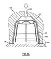
- the capsule 1000 is represented on the Figure 14 inserted into an 1100 beverage extraction device.
- This device 1100 is similar to the extraction device 350 described above. Similar elements are designated by the same reference signs.
- the capsule 1000 is adapted so that the annular edge 380 comes into contact with the annular flange 1016 when the extraction device 1100 is in closed configuration.
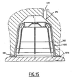
- a variant of the extraction device 1100 is represented on the Figure 15 .
- the conduit 372 for supplying extraction liquid is offset radially with respect to the longitudinal axis Y.
- the capsule 1000 is also adapted for use in drink extraction devices where the arrival of liquid under pressure in the receiving housing 353 is not in the center of the housing 353.
- a variant of the 1000 capsule is presented on Figures 16 and 17 .
- the internal portion 1034 has a hemispherical shape concavity oriented towards the inside of the body 1004. This shape is adapted to allow the rupture of the zone of weakness 1032 at higher pressures in the case where the inner portion 1034 has a frustoconical shape.
- the annular flange 1016 is not bonded to the outer surface 1010b of the outer side wall 1010, but to a front annular face 1066 of the outer side wall 1010. Said front annular face 1066 defines a groove 1068 protruding longitudinally toward the outside. rear and with which cooperates the protuberance 1058 of the annular flange 1016 to strengthen the connection of the annular flange 1016 with the outer side wall 1010.
- the inner surface 1010a of the outer side wall 1010 defines an annular inner shoulder 1070 extending in a radial plane and facing forward.
- the inner shoulder 1070 is recessed axially inwardly of the body 1004 with respect to the front end 1022 of the body 1004 and the annular flange 1016. This inner shoulder 1070 is adapted to support the lid 1006.
- the inner shoulder 1070 is set back relative to the front annular face 1066, the substance is thus not in contact with the second material forming the annular flange 1016.
- the lid 1006 is constituted by a bilayer complex film comprising the filter 1060 and the membrane 1062.
- This complex film is fixed by its periphery on the internal shoulder 1070 so that the lid 1006 is disposed axially inwardly of the body 1004 with respect to the front end 1022 of the body 1004.
- the retraction distance of the lid 1006 from the front end 1022 of the body 1004 is greater than at 1 mm.
- the bottom portion 1038 comprises a plurality of zones of least resistance 1032, each being formed by two lines of weakness intersecting so as to form a cross.
- the zones of least resistance 1032 are four in number. Alternatively, the number of zones of least resistance 1032 is different.
- the bottom portion 1038 comprises a plurality of zones of least resistance 1032, each being formed by a closed circular line of weakness, each delimiting a disk not including the inner portion 1034.
- the areas of less resistance 1032 are three in number. Alternatively, the number of zones of least resistance 1032 is different.
- the bottom portion 1038 comprises two zones of least resistance 1032, each having the shape of a serrated semicircle and extending at the periphery of the bottom portion 1038, along the junction with the outer portion 1036.
- the bottom 12 further comprises two reinforcing ribs 1080 of the central region 1024.
- Each rib 1080 extends longitudinally between the tubular portion 1026 and the peripheral rim 1030.
- Each rib 1080 is interposed between the two zones 1034 of the least resistance. the example shown, the ribs 1080 are thus diametrically opposed to one another.
- These ribs 1080 are intended to concentrate the shear forces due to the force exerted by the pressurized fluid on the bottom 1012 in the extraction device 1100 on the zones of least resistance 1034.
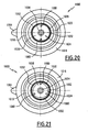
- the bottom portion 1038 comprises three zones of least resistance 1032, each being constituted by a closed line delimiting a crescent whose long side extends along the outer portion 1036.
- the bottom 1012 also comprises reinforcing ribs 1080 of the central region 1024. These ribs 1080 are here three in number and each is interposed between two zones of weakness 1032.
- the bottom portion 1038 comprises a single zone of weakness 1032 consisting of a closed circular line extending along the outer portion 1036.
- the first plastic material is poured, for example injected, into a mold, to form the bottom 1012 and the outer side wall 1010. Then, in a second step, the second plastic material is in turn poured into the mold. mold, so as to form the annular flange 1016.
- the first and second plastic materials being compatible materials, they bind chemically. In particular, a part of the molecules of the first material diffuses into the second material and vice versa. Thus, a thin layer is formed in which the two materials are mixed and the two materials are thus intimately bonded to each other.
- the body part of the capsule in contact with the substance is formed in a material which is inert with respect to the substance, which makes it possible to preserve the substance under optimal conditions, without the risk of degradation of the substance.
- the substance by oxidation or by toxic elements contained in the material in contact with the substance.
- the fact that the first plastic material is not colored in the mass makes it possible to reduce the probability of migration of toxic elements from the capsule to the substance.
- the fact of using a second material for the annular rim makes it possible to reduce the manufacturing cost of the capsule and also makes it possible, by coloring the second material, to easily identify the substance contained in the chamber of the capsule, without risk of migration of the pigments into the substance, the latter not being in contact with the second material.
Description
La présente invention concerne une capsule pour l'extraction d'une boisson sous pression selon le préambule de la revendication 1.The present invention relates to a capsule for the extraction of a drink under pressure according to the preamble of
Cependant, il existe un risque qu'une telle capsule s'affaisse lors de la fermeture du dispositif d'extraction de boisson et/ou de l'injection du liquide sous pressionHowever, there is a risk that such capsule collapses during closure of the beverage extraction device and / or injection of the liquid under pressure
En outre, de telles capsules sont particulièrement chères à produire, en particulier quand elles sont produites en grandes séries.In addition, such capsules are particularly expensive to produce, especially when they are produced in large batches.
De plus, il est difficile de pouvoir à la fois avoir une capsule inerte vis-à-vis de la substance contenue dans la chambre et de marquer la capsule d'un signe distinctif permettant de distinguer sans ambiguïté la substance contenue dans la chambre.In addition, it is difficult to both have a capsule inert vis-à-vis the substance contained in the room and mark the capsule with a distinctive sign to distinguish unambiguously the substance in the room.
Enfin, lorsqu'une telle capsule est utilisée dans un dispositif d'extraction comportant un logement de réception de la capsule et un support contre lequel est appliquée la capsule, l'opercule est plaqué contre le support, ce qui empêche un écoulement satisfaisant du liquide à travers la capsule.Finally, when such a capsule is used in an extraction device comprising a housing for receiving the capsule and a support against which the capsule is applied, the lid is pressed against the support, which prevents a satisfactory flow of the liquid. through the capsule.
D'autres capsules sont connues de
Un but de l'invention est de fournir une capsule à coût réduit. D'autres buts de l'invention sont de proposer une capsule réalisée dans un matériau inerte vis-à-vis de la substance et portant une marque distinctive permettant d'identifier facilement la substance contenue dans la chambre, de proposer une capsule compatible avec de nombreux dispositifs d'extraction de boisson, et de fournir une capsule permettant de limiter le risque d'affaissement tout en permettant l'extraction d'une boisson.An object of the invention is to provide a reduced cost capsule. Other objects of the invention are to propose a capsule made of a material which is inert with respect to the substance and bearing a distinctive mark making it possible to easily identify the substance contained in the chamber, to propose a capsule compatible with numerous beverage extraction devices, and provide a capsule to limit the risk of sagging while allowing the extraction of a drink.
A cet effet, l'invention a pour objet, selon un premier aspect, une capsule selon la revendication 1.For this purpose, according to a first aspect, the subject of the invention is a capsule according to
Selon d'autres modes de réalisation, ladite capsule comporte une ou plusieurs des caractéristiques des revendications 2 à 14.According to other embodiments, said capsule comprises one or more of the features of
L'invention a également pour objet, selon un deuxième aspect, un système comprenant une capsule selon le premier aspect de l'invention, et un dispositif d'extraction comportant un logement destiné à recevoir la capsule, un support et un conduit d'amenée de liquide d'extraction.The subject of the invention is also, in a second aspect, a system comprising a capsule according to the first aspect of the invention, and an extraction device comprising a housing intended to receive the capsule, a support and a delivery duct. extraction liquid.
L'invention sera mieux comprise à la lecture de la description qui va suivre, donnée uniquement à titre d'exemple et faite en se référant aux dessins annexés, sur lesquels :
- la
Figure 1 représente une vue en perspective d'une première variante d'une capsule selon un premier mode de réalisation non conforme à l'invention ; - la
Figure 2 est une vue en coupe longitudinale de la capsule de laFigure 1 ; - la
Figure 3 est une vue de face de la capsule de laFigure 1 ; - les
Figures 4 et5 sont des vues de la capsule de laFigure 1 , installée dans un dispositif d'extraction en configurations respectivement partiellement ouverte et fermée ; - la
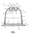
Figure 6 est une vue en coupe longitudinale d'une seconde variante de la capsule selon le premier mode de réalisation ; - la
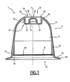
Figure 7 est une vue en coupe longitudinale d'une troisième variante de la capsule selon le premier mode de réalisation ; - la
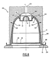
Figure 8 est une vue de la capsule de laFigure 6 , installée dans un dispositif d'extraction en configuration fermée ; - la
Figure 9 est une vue en perspective d'une première variante d'une capsule selon un deuxième mode de réalisation conforme à l'invention ; - la
Figure 10 est une vue en coupe longitudinale de la capsule de laFigure 9 ; - la
Figure 11 est une vue de derrière de la capsule de laFigure 9 ; - la
Figure 12 est une vue d'un détail marqué XII sur laFigure 10 ; - la
Figure 13 est une vue d'un détail marqué XIII sur laFigure 10 ; - la
Figure 14 est une vue de la capsule de laFigure 8 , installée dans un premier dispositif d'extraction en configuration fermée ; - la
Figure 15 est une vue similaire à laFigure 14 , la capsule étant installée dans un deuxième dispositif d'extraction en configuration fermée ; - la
Figure 16 est une vue en coupe longitudinale d'une deuxième variante d'une capsule selon le deuxième mode de réalisation ; - la
Figure 17 est une vue d'un détail marqué XVII sur laFigure 16 ; - la
Figure 18 est une vue de derrière d'une troisième variante d'une capsule selon le deuxième mode de réalisation ; - la
Figure 19 est une vue de derrière d'une quatrième variante d'une capsule selon le deuxième mode de réalisation : - la
Figure 20 est une vue de derrière d'une cinquième variante d'une capsule selon le deuxième mode de réalisation; - la
Figure 21 est une vue de derrière d'une sixième variante d'une capsule selon le deuxième mode de réalisation; et - la
Figure 22 est une vue de derrière d'une septième variante d'une capsule selon le deuxième mode de réalisation.
- the
Figure 1 represents a perspective view of a first variant of a capsule according to a first embodiment not in accordance with the invention; - the
Figure 2 is a longitudinal sectional view of the capsule of theFigure 1 ; - the
Figure 3 is a front view of the capsule of theFigure 1 ; - the
Figures 4 and5 are views of the capsule of theFigure 1 installed in an extraction device in respectively partially open and closed configurations; - the
Figure 6 is a longitudinal sectional view of a second variant of the capsule according to the first embodiment; - the
Figure 7 is a longitudinal sectional view of a third variant of the capsule according to the first embodiment; - the
Figure 8 is a view of the capsule of theFigure 6 installed in an extraction device in a closed configuration; - the
Figure 9 is a perspective view of a first variant of a capsule according to a second embodiment according to the invention; - the
Figure 10 is a longitudinal sectional view of the capsule of theFigure 9 ; - the
Figure 11 is a back view of the capsule of theFigure 9 ; - the
Figure 12 is a view of a detail marked XII on theFigure 10 ; - the
Figure 13 is a view of a detail marked XIII on theFigure 10 ; - the
Figure 14 is a view of the capsule of theFigure 8 installed in a first extraction device in a closed configuration; - the
Figure 15 is a view similar to theFigure 14 the capsule being installed in a second extraction device in a closed configuration; - the
Figure 16 is a longitudinal sectional view of a second variant of a capsule according to the second embodiment; - the
Figure 17 is a view of a detail marked XVII on theFigure 16 ; - the
Figure 18 is a rear view of a third variant of a capsule according to the second embodiment; - the
Figure 19 is a rear view of a fourth variant of a capsule according to the second embodiment: - the
Figure 20 is a rear view of a fifth variant of a capsule according to the second embodiment; - the
Figure 21 is a rear view of a sixth variant of a capsule according to the second embodiment; and - the
Figure 22 is a rear view of a seventh variant of a capsule according to the second embodiment.
La capsule 1 selon le premier mode de réalisation non conforme à l'invention, représentée sur les
Le corps 4 présente une forme générale de coupelle et comprend une paroi latérale 10, un fond 12 fermant une extrémité arrière 20 fermée du corps 4, et un rebord annulaire 16 entourant une extrémité avant 22 ouverte du corps 4.The body 4 has a general cup shape and comprises a
Le corps 4 est réalisé d'un seul tenant. La paroi latérale 10, le fond 12 et le rebord annulaire 16 sont venus de matière. Le corps 4 est réalisé en un matériau étanche à l'air et à l'eau, par exemple dans un matériau plastique ou dérivé du plastique, ou en métal.The body 4 is made in one piece. The
La paroi latérale 10 s'étend à partir du fond 12 suivant un axe longitudinal X jusqu'à l'extrémité avant 22 du corps 4.The
La paroi latérale 10 comprend un épaulement intérieur 14. L'épaulement 14 s'étend dans un plan radial et est orienté vers l'avant.The
La paroi latérale 10 est sensiblement tronconique de révolution autour de l'axe longitudinal X. La paroi latérale 10 comprend un tronçon arrière 18, relativement souple, s'étendant à partir du fond 12 et un tronçon avant 19, relativement rigide, prolongeant axialement le tronçon arrière 18. Le tronçon avant 19 présente une épaisseur croissante axialement, supérieure à celle du tronçon arrière 18.The
Le fond 12 présente une région périphérique 23, s'étendant radialement vers l'intérieur à partir de la paroi latérale 10, et une région centrale 24.The bottom 12 has a
La région périphérique 23 est arrondie. Elle s'étend radialement vers l'intérieur et axialement vers l'arrière à partir de la paroi latérale 10, et présente une concavité tournée vers l'intérieur du corps 4.The
La région centrale 24 comprend une nervure annulaire 26 faisant saillie axialement vers l'intérieur du corps 4 à partir de la région périphérique 23. La nervure annulaire 26 définit une tranchée annulaire 28 ouverte à l'extérieur du corps 4 vers l'arrière. La nervure annulaire 26 définit un plot central 30 creux faisant saillie axialement à partir du fond de la tranchée annulaire 28 en définissant un évidement à l'intérieur du corps 4.The
La région centrale 24 présente au moins une zone de moindre résistance 32 prévue pour rompre sous l'effet d'un fluide sous pression. Les zones de moindre résistance 32 sont prévues par exemple sous la forme de zones de moindre épaisseur de la région centrale 24, définies par exemple par des indentations ménagée dans la région centrale 24.The
Les zones de moindre résistance 32 sont prévues dans des parois de la nervure annulaire 26 et/ou sur le plot central 30.Areas of
Dans l'exemple illustré, la nervure annulaire 26 comprend une portion externe 36 tubulaire s'étendant axialement vers l'intérieur à partir de la région périphérique 23, une portion interne 34 tubulaire délimitant une face latérale du plot central 30 et une portion de fond 38 s'étendant radialement entre la portion externe 36 et la portion interne 34 en conférant à la nervure annulaire 26 une section transversale sensiblement en forme de « U ».In the illustrated example, the
Comme représenté sur la
En variante, la région centrale 24 est dépourvue de zone de moindre résistance 32 dans le plot central 30. En variante ou en option, la nervure annulaire 26 possède des zones de moindre résistance 32 dans la portion externe 36 et/ou la portion interne 34.Alternatively, the
Dans une autre variante possible différente de celle de la
Comme représenté sur la
De préférence, la région périphérique 23 possède une surépaisseur le long du bord extérieur 44, de façon à renforcer le bord extérieur 44. La région périphérique 23 présente par exemple une épaisseur croissante depuis la paroi latérale 10 vers le bord extérieur 44.Preferably, the
L'épaulement interne 14 est annulaire et fait saillie radialement depuis la paroi latérale 10 vers l'intérieur du corps 4. II est en retrait axialement vers intérieur du corps 4 par rapport à l'extrémité avant 22 du corps 4 et au rebord annulaire 16.The
L'opercule 6 est fixé par sa périphérie sur l'épaulement interne 14 de sorte que l'opercule 6 est disposé en retrait axialement vers l'intérieur du corps 4 par rapport à l'extrémité avant 22 du corps 4. De préférence, la distance de retrait de l'opercule 6 par rapport à l'extrémité avant 22 du corps 4 est supérieure à 1mm.The
L'opercule 6 ferme l'extrémité avant 22 du corps 4.The
L'opercule 6 comprend un filtre 49 de sortie propre à laisser passer un fluide sous pression en retenant la substance contenue dans la chambre 8. Le filtre 49 est en papier filtre poreux, en matériau plastique tissé ou en film plastique perforé.The
L'opercule 6 comprend en outre une membrane 50 étanche à l'air et à l'eau doublant le filtre 49. La membrane 50 présente des lignes d'affaiblissement 52, de sorte que la membrane 50 est propre à se déchirer sous le seul l'effet de la pression d'un liquide. Dans l'exemple représenté sur les
Le filtre 49 est disposé entre la chambre 8 et la membrane 50. Le filtre 49 et la membrane 50 sont accolés l'un à l'autre. Le filtre 49 et la membrane 50 se présentent par exemple sous la forme d'un film complexe bicouche.The
Le rebord annulaire 16 s'étend radialement vers l'extérieur à partir de la paroi latérale 10. Le rebord annulaire 16 définit l'extrémité avant 22 du corps 4. Le rebord 16 présente une région marginale 54 libre. Il ne supporte pas d'élément d'étanchéité rapporté ou de relief d'étanchéité déformable. Tel que représenté sur les
La capsule 1 est destinée à être disposée dans un dispositif d'extraction 350, représenté sur les
Le dispositif d'extraction 350 comporte un élément de réception 352 creux, délimitant un logement 353 de réception du la capsule 1, et un support 354. Il est propre à être manoeuvré entre une configuration ouverte dans laquelle l'élément de réception 352 et le support 354 sont mutuellement écarté pour introduire la capsule 1 dans l'élément de réception 352, et une position fermée, représentée sur la
Le logement 353 présente une face latérale intérieure 360, un fond de logement 370 et un conduit 372 d'amenée de liquide d'extraction débouchant sur le fond de logement 370, sensiblement au centre et une ouverture 376 d'introduction de la capsule 1.The housing 353 has an
La face latérale intérieure 360 est de révolution autour d'un axe longitudinal Y. Sur l'exemple représenté, elle est sensiblement tronconique. Lorsque la capsule 1 est placée dans le dispositif d'extraction 350, les axes longitudinaux X de la capsule 1 et Y du logement 353 se confondent sensiblement.The
L'élément de réception 352 présente un bord annulaire 380 entourant l'ouverture 376.The receiving
La capsule 1 présente une longueur axiale suffisante pour que, en configuration fermée du dispositif d'extraction 350, la capsule 1 soit en appui par son rebord annulaire 16 contre le support 354 et par son fond 12 contre le fond de logement 370 suivant une ligne de contact annulaire fermée 122, définie de préférence sur la région périphérique 23 le long du bord extérieur 44 de la tranchée annulaire 28.The
La capsule 1 est avantageusement adaptée pour se déformer élastiquement sous l'effet d'une force axiale F de compression pour assurer un contact suffisant entre le fond 12 et le fond de logement 370.The
En option la capsule 1 est adaptée pour que, sous l'effet de la force axiale F de compression, au moins une zone annulaire 130 du fond 12 et/ou de la paroi latérale 10 de la capsule 1 se dilate radialement vers l'extérieur de façon à assurer un contact 128 supplémentaire avec la face latérale 360 du logement 353, suivant une ligne de contact annulaire fermée.Optionally the
Le procédé d'extraction de la capsule 1 par le dispositif d'extraction 350 va maintenant être décrit.The extraction process of the
La capsule 1 est d'abord placée dans le dispositif 350 en configuration ouverte, puis le dispositif 350 est manoeuvré pour se déplacer en configuration fermée.The
Lors de ce déplacement vers la configuration fermée, la capsule 1 vient en appui par son rebord annulaire 16 contre le support 354 puis l'élément de réception 352 appuie axialement sur le fond 12 de la capsule 1, de sorte que le contact 122 se crée, et le corps 4 se déforme dans son ensemble de sorte que le contact 128 se crée avec l'élément de réception 352 du dispositif 350.During this movement towards the closed configuration, the
Une fois le dispositif 350 en configuration fermée, le fluide d'extraction est injecté sous pression par le conduit 372. Sous l'effet de la pression du fluide d'extraction, les zones de moindre résistance 32 de la région centrale 24 du fond 12 se rompent et le fluide d'extraction pénètre dans la capsule 1.Once the
La pression de liquide dans la capsule 1 augmente alors et, sous l'effet de cette pression, la membrane de sortie 50 se déchire. Le fluide s'échappe alors hors de la capsule 1 en traversant l'opercule 6 en étant filtré par le filtre 49.The pressure of liquid in the
Le fond renforcé par une nervure annulaire permet de réaliser le corps de la capsule en un matériau relativement souple, déformable, sans que le fond ne s'effondre vers l'intérieur de la capsule sous l'effet de la pression de fluide. La convexité du fond permet de définir un fond résistant et déformable élastiquement, avec un volume de la chambre important permettant de charger une plus grande quantité de substance dans la capsule. La nervure délimitant dans la face extérieure une tranchée annulaire permet d'améliorer l'injection du liquide d'extraction dans la capsule. La présence d'un rebord annulaire permet d'augmenter la stabilité de la capsule sur le support du dispositif d'extraction.The bottom reinforced by an annular rib enables the body of the capsule to be made of a relatively flexible, deformable material, without the bottom collapsing towards the inside of the capsule under the effect of the fluid pressure. The convexity of the bottom makes it possible to define a resilient and elastically deformable bottom, with a volume of the large chamber making it possible to load a larger quantity of substance into the capsule. The rib delimiting in the outer face an annular trench makes it possible to improve the injection of the extraction liquid into the capsule. The presence of an annular rim makes it possible to increase the stability of the capsule on the support of the extraction device.
La capsule possède un corps en forme de coupelle dont le fond est étanche à l'air et à l'eau, le corps étant fermée par un opercule étanche à l'air et à l'eau. L'étanchéité de la capsule permet de conserver la substance à l'abri de l'air et de l'humidité. L'opercule possède une membrane se déchirant sous l'effet du fluide sous pression permettant une ouverture appropriée de l'opercule à partir d'un niveau de pression déterminé, avec un effet retard bénéfique pour une extraction de qualité. L'opercule en retrait axialement vers l'intérieur du corps évite toute interférence avec le support du dispositif d'extraction avant l'ouverture de la membrane, et permet ainsi une ouverture maîtrisée de la capsule. La membrane associée à un filtre permet d'assurer une extraction de la substance dans des conditions de pression satisfaisantes avec une retenue efficace de la substance à l'intérieur de la capsule. L'opercule fourni sous la forme d'un film complexe facilite la fabrication de la capsule à faible coût.The capsule has a cup-shaped body whose bottom is airtight and watertight, the body being closed by a seal that is airtight and watertight. The tightness of the capsule keeps the substance safe from air and moisture. The cover has a membrane tearing under the effect of the pressurized fluid allowing appropriate opening of the cap from a determined pressure level, with a beneficial delay effect for a quality extraction. The operculum recessed axially towards the inside of the body avoids any interference with the support of the extraction device before the opening of the membrane, and thus allows controlled opening of the capsule. The membrane associated with a filter ensures extraction of the substance under satisfactory pressure conditions with effective retention of the substance inside the capsule. The operculum provided in the form of a complex film facilitates the manufacture of the capsule at low cost.
Les variantes de capsule illustrées sur les
Tel qu'illustré sur la
Un tel rebord 16 permet de garantir et de renforcer le contact 122 entre le fond 12 de la capsule 1 et le fond de logement 370 à la fermeture du dispositif 350, tout en pouvant se déformer pour permettre la fermeture du dispositif d'extraction 350.Such a
La capsule 1000 selon le deuxième mode de réalisation, représentée sur les
Le corps 1004 présente une forme générale de coupelle et est étanche à l'air et à l'eau. Il comprend une paroi latérale extérieure 1010, un fond 1012 fermant une extrémité arrière 1020 du corps 1004, et un rebord annulaire 1016 entourant une extrémité avant 1022 ouverte du corps 1004.The
La paroi latérale extérieure 1010 et le fond 1012 sont venus de matière et sont réalisés en un premier matériau plastique étanche à l'air et à l'eau. Le premier matériau plastique est choisi pour être inerte vis-à-vis de la substance contenue dans la capsule 1000. De préférence, ledit premier matériau est translucide et n'est pas coloré dans la masse, de façon à éviter la diffusion de la coloration dans la substance. Typiquement, le deuxième matériau plastique est du polyamide. Le polyamide n'interfère pas avec les produits alimentaires et constitue une barrière à l'air et à l'eau très performante.The
Le rebord annulaire 1016 est constitué d'un deuxième matériau plastique, différent du premier matériau plastique. Le deuxième matériau plastique est préférentiellement choisi pour être un matériau de faible coût. Celui-ci n'étant pas en contact avec la substance, ses propriétés vis-à-vis de la substance n'entrent pas en compte dans le choix du deuxième matériau. Typiquement, le deuxième matériau plastique est du polyuréthane, qui est un matériau peu coûteux.The
De préférence, les premier et deuxième matériaux plastiques sont des matériaux compatibles, c'est-à-dire des matériaux adaptés pour polymériser l'un avec l'autre.Preferably, the first and second plastic materials are compatible materials, i.e. materials adapted to polymerize with each other.
Ainsi, il est possible de produire des capsules 1000 à coût réduit. Ces capsules étant destinées à être produites en très grandes séries, cela permet de réaliser des économies importantes.Thus, it is possible to produce 1000 capsules at reduced cost. These capsules being intended to be produced in very large series, this allows significant savings.
De préférence, le deuxième matériau est coloré dans la masse. Ainsi, il est possible de colorer différemment les rebords annulaires 1016 de capsules 1000 contenant différentes substances, de façon à distinguer aisément une capsule 1000 contenant une première substance d'une autre capsule 1000 contenant une deuxième substance, différente de la première.Preferably, the second material is colored in the mass. Thus, it is possible to color differently the
La paroi latérale extérieure 1010 s'étend à partir du fond 1012 suivant un axe longitudinal X jusqu'à l'extrémité avant 1022 du corps 1004.The
La paroi latérale extérieure 1010 est sensiblement tronconique de révolution autour de l'axe longitudinal X. Elle est rigide. Elle présente une surface intérieure 1010a, orientée vers la chambre 1008, et une surface extérieure 1010b, à l'opposée de la surface intérieure 1010a.The
Le fond 1012 comprend une région périphérique 1023 et une région centrale 1024.The bottom 1012 comprises a
La région périphérique 1023 est rigide. Elle est arrondie et s'étend radialement vers l'intérieur et axialement vers l'arrière à partir de la paroi latérale extérieure 1010, et présente une concavité tournée vers l'intérieur du corps 1004. Elle s'étend ainsi depuis la paroi latérale extérieure 1010 jusqu'à l'extrémité arrière 1020 du corps 1004. L'extrémité arrière 1020 est typiquement une ligne fermée, par exemple un cercle.
La région centrale 1024 rentre axialement vers l'intérieur de la chambre 1008 à partir de la région périphérique. La région centrale 1024 définit ainsi dans le fond 1012 un évidement 1028 à l'extérieur du corps 1004.
La région centrale 1024 comprend une portion externe 1036 tubulaire s'étendant axialement vers l'intérieur de la chambre 1008 à partir de la région périphérique 1023, une portion de fond 1038 s'étendant radialement vers l'intérieur à partir de l'extrémité intérieure de la potion externe 1036 et fermant l'évidement 1028, et une portion interne 1034 centrale faisant saillie vers l'extérieur à partir de la portion de fond 1038.The
La portion interne 1034 définit un plot central creux 1030 dans l'évidement 1028. Celui-ci présente ainsi une forme annulaire. La portion externe 1036, la portion de fond 1038 et la portion interne 1034 définissent une nervure 1026 annulaire dans la région centrale 1024.The
La portion de fond 1038 comprend au moins une zone de moindre résistance 1032 prévue pour rompre sous l'effet d'un fluide sous pression. De préférence, la ou chaque zone de moindre résistance est prévue pour rompre à une pression du fluide sous pression comprise entre 1 et 3 bars.The
La ou chaque zone de moindre résistance 1032 est prévue par exemple sous la forme de zones de moindre épaisseur de, comme représenté sur la
Dans l'exemple illustré sur la
La forme de la portion interne 1034 conditionne l'effort de cisaillement axial généré par un liquide sous pression présent dans l'évidement 1028.The shape of the
Dans les
En variante, la portion interne 1034 est s'étend dans un plan radial. A une pression déterminée du fluide présent dans l'évidement 1028, une portion interne 1034 plane induit un effort de cisaillement plus élevé qu'une portion interne saillante vers l'extérieur.In a variant, the
Le corps 1004 comprend également des nervures longitudinales 1042 de rigidification de la paroi latérale extérieure 1010 et des nervures radiales 1044 de rigidification du fond 1012.The
Chaque nervure longitudinale 1042 s'étend longitudinalement le long de la paroi latérale extérieure 1010, de préférence, comme représenté, le long de la surface intérieure 1010a. Ainsi, les nervures longitudinales sont adaptées pour favoriser l'émulsion entre le fluide sous pression et la substance contenue dans la chambre 1008. En variante, chaque nervure longitudinale 1042 s'étend le long de la surface extérieure 1010b.Each
Chaque nervure radiale 1044 s'étend radialement entre la portion externe 1036 et la région périphérique 1023. Les nervures radiales 1044 rigidifient le fond 12 et favorisent ainsi la génération des efforts de cisaillement induits par la pression du fluide sous pression directement sur la ou chaque zone de faiblesse 1032. Dans l'exemple représenté sur les
Le rebord annulaire 1016 s'étend radialement vers l'extérieur, d'une bordure annulaire intérieure 1046 jusqu'à une bordure annulaire extérieure 1048, à partir de la surface extérieure 1010b de la paroi latérale extérieure 1010. Il définit l'extrémité avant 1022 du corps 1004. Il ne supporte pas d'élément d'étanchéité rapporté ou de relief d'étanchéité déformable. De préférence, il est sensiblement plan. La bordure annulaire extérieure 1048 est libre.The
Comme visible sur le détail représenté sur la
L'épaulement 1050 est en retrait vers l'arrière par rapport à l'extrémité avant 1022. Il s'étend radialement et parallèlement à l'extrémité avant 1022, entre une extrémité intérieure 1054 et une extrémité extérieure 1056.The
La gorge 1052 est formée dans l'épaulement 1050 et fait saillie longitudinalement vers l'arrière depuis l'extrémité intérieure 1054 de l'épaulement 1050.The
Le rebord annulaire 1016 comprend une protubérance annulaire 1058 faisant saillie longitudinalement depuis la bordure annulaire intérieure 1046 dans la gorge 1052. La protubérance 1058 coopère avec la gorge 1052 pour renforcer la liaison du rebord annulaire 1016 à la paroi latérale extérieure 1010.The
Ainsi, une partie de la paroi latérale extérieure 1010 s'étend entre le rebord annulaire 1016 et la chambre 1008, ce qui évite que la substance ne soit en contact avec le deuxième matériau.Thus, a portion of the
De retour à la
L'opercule 1006 comprend un filtre 1060 de sortie propre à laisser passer un fluide sous pression en retenant la substance contenue dans la chambre 1008. Le filtre 1060 est en papier filtre poreux, en matériau plastique tissé ou en film plastique perforé. De préférence, le filtre 1060 est, comme représenté, disposé en retrait de l'extrémité avant 1022, vers la chambre 1008, et est fixé sur sa périphérie à la surface intérieure 1010a de la paroi latérale extérieure 1010. Le filtre 1060 est par exemple disposé entre 1 et 1,5 mm en retrait par rapport à l'extrémité avant 1022.The
L'opercule 1006 comprend en outre une membrane 1062 étanche à l'air et à l'eau doublant le filtre 1060. De préférence, la membrane 1062 est fixée, par exemple soudée, sur le rebord annulaire 1016. La membrane 1062 s'étend le long de l'extrémité avant 1022 du corps 1004. La membrane 1062 permet de conserver la substance dans une atmosphère inerte, de façon à éviter toute oxydation de la substance.The
La membrane 1062 est pelable, c'est-à-dire qu'elle peut être facilement désolidarisée du corps 1004. A cet effet, elle comprend une languette 1064 s'étendant radialement vers l'extérieur depuis le rebord annulaire 1016, pour permettre à un utilisateur de retirer aisément la membrane 1062 avant utilisation de la capsule 1000 dans un dispositif d'extraction.The
En option, la membrane 1062 présente des lignes d'affaiblissement (non représentées), de sorte que la membrane 1062 est propre à se déchirer sous le seul l'effet de la pression d'un liquide. Ainsi, dans le cas où un utilisateur aurait oublié de retirer la membrane 1062 avant d'insérer la capsule 1000 dans un dispositif d'extraction, l'extraction peut être quand même exécutée normalement, sans risque d'endommagement pour le dispositif d'extraction.Optionally, the
Le filtre 1060 est disposé entre la chambre 1008 et la membrane 1062. L'espace entre le filtre 1060 et la membrane 1062 est de préférence rempli avec un gaz inerte, typiquement avec de l'azote.The
La capsule 1000 est représentée sur la
Une variante du dispositif d'extraction 1100 est représentée sur la
Une variante de la capsule 1000 est présentée sur les
Dans cette variante, la portion interne 1034 a une forme hémisphérique à concavité orientée vers l'intérieur du corps 1004. Cette forme est adaptée pour permettre la rupture de la zone de faiblesse 1032 à des pressions supérieures au cas où la portion interne 1034 présente une forme tronconique.In this variant, the
Le rebord annulaire 1016 n'est pas lié à la surface extérieure 1010b de la paroi latérale extérieure 1010, mais à une face annulaire avant 1066 de la paroi latérale extérieure 1010. Ladite face annulaire avant 1066 définit une gorge 1068 faisant saillie longitudinalement vers l'arrière et avec laquelle coopère la protubérance 1058 du rebord annulaire 1016 pour renforcer la liaison du rebord annulaire 1016 avec la paroi latérale extérieure 1010.The
La surface intérieure 1010a de la paroi latérale extérieure 1010 définit un épaulement intérieur annulaire 1070 s'étendant dans un plan radial et étant orienté vers l'avant. L'épaulement interne 1070 est en retrait axialement vers l'intérieur du corps 1004 par rapport à l'extrémité avant 1022 du corps 1004 et au rebord annulaire 1016. Cet épaulement intérieur 1070 est adapté pour supporter l'opercule 1006.The
L'épaulement intérieur 1070 étant en retrait par rapport à la face annulaire avant 1066, la substance n'est ainsi pas en contact avec le deuxième matériau formant le rebord annulaire 1016.The
De même que dans le premier mode de réalisation, l'opercule 1006 est constitué par un film complexe bicouche comprenant le filtre 1060 et la membrane 1062. Ce film complexe est fixé par sa périphérie sur l'épaulement interne 1070 de sorte que l'opercule 1006 est disposé en retrait axialement vers l'intérieur du corps 1004 par rapport à l'extrémité avant 1022 du corps 1004. De préférence, la distance de retrait de l'opercule 1006 par rapport à l'extrémité avant 1022 du corps 1004 est supérieure à 1 mm.As in the first embodiment, the
D'autres variantes de la capsule 1000 sont présentées sur les
Dans la variante représentée sur la
Dans la variante représentée sur la
Dans la variante représentée sur la
Le fond 12 comprend en outre deux nervures 1080 de renforcement de la région centrale 1024. Chaque nervure 1080 s'étend longitudinalement entre la portion tubulaire 1026 et la bordure périphérique 1030. Chaque nervure 1080 est interposée entre les deux zones de moindre résistance 1034. Dans l'exemple représenté, les nervures 1080 sont ainsi diamétralement opposées l'une à l'autre.The bottom 12 further comprises two reinforcing
Ces nervures 1080 sont destinées à concentrer les efforts de cisaillement dus à la force exercée par le fluide sous pression sur le fond 1012 dans le dispositif d'extraction 1100 sur les zones de moindre résistance 1034.These
Dans la variante représentée sur la
Le fond 1012 comprend également des nervures 1080 de renforcement de la région centrale 1024. Ces nervures 1080 sont ici au nombre de trois et chacune est intercalée entre deux zones de moindre résistance 1032.The bottom 1012 also comprises reinforcing
Enfin, dans la variante présentée sur la
Le procédé de fabrication de la capsule 1000 va être brièvement décrit, en regard de la
Dans un premier temps, le premier matériau plastique est coulé, par exemple injecté, dans un moule, pour former le fond 1012 et la paroi latérale extérieure 1010. Puis, dans un deuxième temps, le deuxième matériau plastique est à son tour coulé dans le moule, de façon à former le rebord annulaire 1016.In a first step, the first plastic material is poured, for example injected, into a mold, to form the bottom 1012 and the
Les premier et deuxième matériaux plastiques étant des matériaux compatibles, ils se lient chimiquement. En particulier, une partie des molécules du premier matériau diffuse dans le deuxième matériau et vice-versa. Ainsi, il se forme une fine couche dans laquelle les deux matériaux sont mélangés et les deux matériaux sont ainsi intimement liés l'un avec l'autre.The first and second plastic materials being compatible materials, they bind chemically. In particular, a part of the molecules of the first material diffuses into the second material and vice versa. Thus, a thin layer is formed in which the two materials are mixed and the two materials are thus intimately bonded to each other.
Grâce à l'invention, la partie du corps de la capsule en contact avec la substance est formée dans un matériau inerte vis-à-vis de la substance, ce qui permet de conserver la substance dans des conditions optimales, sans risques de dégradation de la substance par oxydation ou par des éléments toxiques contenus dans le matériau en contact avec la substance.Thanks to the invention, the body part of the capsule in contact with the substance is formed in a material which is inert with respect to the substance, which makes it possible to preserve the substance under optimal conditions, without the risk of degradation of the substance. the substance by oxidation or by toxic elements contained in the material in contact with the substance.
En outre, le fait que le premier matériau plastique ne soit pas coloré dans la masse permet de réduire la probabilité de migration d'éléments toxiques de la capsule vers la substance.In addition, the fact that the first plastic material is not colored in the mass makes it possible to reduce the probability of migration of toxic elements from the capsule to the substance.
Enfin, le fait d'utiliser un deuxième matériau pour le rebord annulaire permet de réduire le coût de fabrication de la capsule et permet en outre, par coloration du deuxième matériau, d'identifier aisément la substance contenue dans la chambre de la capsule, sans risque de migration des pigments dans la substance, celle-ci n'étant pas en contact avec le deuxième matériau.Finally, the fact of using a second material for the annular rim makes it possible to reduce the manufacturing cost of the capsule and also makes it possible, by coloring the second material, to easily identify the substance contained in the chamber of the capsule, without risk of migration of the pigments into the substance, the latter not being in contact with the second material.
On notera que la description donnée ci-dessus n'est nullement restrictive, et les caractéristiques des différentes variantes et des différents modes de réalisation peuvent être combinées les unes avec les autres sans sortir du cadre de l'invention.Note that the description given above is not restrictive, and the characteristics of different variants and different embodiments can be combined with each other without departing from the scope of the invention.
Claims (15)
- A capsule (1000) for extracting a pressurized drink, of the type comprising a body (1004) in the form of a cup and a seal (1006) delimiting together a chamber (1008) containing a substance for preparing a drink, the body (1004) comprising:- an outer side wall (1010), which is substantially frusto-conical- a base (1012), made together with the outer side wall (1010) in the same material and closing the outer side wall (1010) at a rear end (1020) of the body (1004), and- an annular rim (1016) extending radially outwards from the outer side wall (1010) and delimiting the front end (1022) of the body (1004),the seal (1406) closing the outer side wall (1010) at the front end (1022), the capsule (1000) being adapted so as to be positioned in an extraction device (1100) so that a pressurized extraction liquid penetrates into the capsule (1000) through the base (1012) and flows out therefrom through the seal (1006) characterized in that the base (1012) and the wall (1010) are made in a first plastic material, the annular rim (1016) being formed in a second plastic material, différent from the first plastic material, the first and second plastic materials being chemically bound together, a layer being formed in which both materials are mixed.
- The capsule (1000) according to claim 1, characterized in that the first plastic material is polyamide.
- The capsule (1000) according to claim 1 or 2, characterized in that the second plastic material is polyurethane.
- The capsule (1000) according to any of the preceding claims, characterized in that the outer side wall (1010) comprises an inner surface (1010a), oriented towards the chamber (1008), and an outer surface (1010b) opposite to the inner surface (1010a), the outer surface (1010b) defining a shoulder (1050) for connecting the annular rim (16, 1016) to the outer side wall (10, 1010), the shoulder (1050) extending radially and parallel to the front end (1022) of the capsule (1000).
- The capsule (1000) according to any of the preceding claims, characterized in that the outer side wall (1010) defines a groove (1052, 1068) for connecting the annular rim (1016) to the outer side wall (1010), the annular rim (1016) including an annular protrusion (1058) cooperating with the groove (1052, 1068) for reinforcing the connection of the annular rim (1016) to the outer side wall (1010).
- The capsule (1000) according to any of the preceding claims, characterized in that the first plastic material is not colored in the bulk.
- The capsule (1000) according to any of the preceding claims, characterized in that the second plastic material is colored in the bulk.
- The capsule (1000) according to any of the preceding claims, characterized in that the base (1012) is formed by a peripheral region (1023) delimiting a rear end (1020) of the body (1004), and by a central region (1024) entering towards the inside of the capsule (1000) relatively to the rear end (1020) while defining a recess (1028) outside the body (1004), the central region (1024) comprising at least an area of lower strength (1032) intended to at least partly break under the pressure of a pressurized liquid.
- The capsule (1000) according to claim 8, characterized in that said or each area of lower strength (1032) is adapted so as to break at a pressure of the pressurized liquid comprised between 1 and 3 bars.
- The capsule (1000) according to claim 8 or 9, characterized in that, before breakage of said or each area of lower strength (1032), the base (1012) and the outer side wall (1010) of the body (1004) are impervious to air and to liquids.
- The capsule (1000) according to any of the preceding claims, characterized in that the seal (1006) comprises a filter (1060) and a membrane (1062).
- The capsule (1000) according to claim 11, characterized in that the filter (1060) is positioned set back from the front end (1022) of the body (1004) towards the chamber (1008), the membrane (1062) extending along the front end (1022).
- The capsule (1000) according to claim 12, characterized in that the gap between the filter (1060) and the membrane (1062) is filled with nitrogen.
- The capsule (1000) according to any of claims 11 to 13, characterized in that the membrane (1062) is peelable.
- A system comprising a capsule (1000) according to any of the preceding claims and an extraction device (1100) including a housing intended for receiving the capsule (1000), a support, and a conduit (372) for supplying a pressurized extraction liquid.
Priority Applications (21)
| Application Number | Priority Date | Filing Date | Title |
|---|---|---|---|
| PL10306432T PL2394539T3 (en) | 2010-06-11 | 2010-12-16 | Bi-material capsule |
| PCT/FR2011/051321 WO2011154666A1 (en) | 2010-06-11 | 2011-06-09 | Two-material capsule |
| RU2013100977/12A RU2569281C2 (en) | 2010-06-11 | 2011-06-09 | Capsule with gap start zone |
| CN201180039592.2A CN103079436B (en) | 2010-06-11 | 2011-06-09 | Having breaks opens the container in region |
| CA2824135A CA2824135A1 (en) | 2010-06-11 | 2011-06-09 | Two-material capsule |
| CA2802166A CA2802166A1 (en) | 2010-06-11 | 2011-06-09 | Capsule having a rupture initiation area |
| PCT/FR2011/051320 WO2011154665A1 (en) | 2010-06-11 | 2011-06-09 | Capsule having a rupture initiation area |
| JP2013513738A JP2013530750A (en) | 2010-06-11 | 2011-06-09 | Capsule with rupture initiation region |
| BR112013015161A BR112013015161A2 (en) | 2010-12-16 | 2011-06-09 | capsule for extracting a beverage under pressure and system |
| JP2013543849A JP2014501583A (en) | 2010-06-11 | 2011-06-09 | Dual material capsule |
| RU2013132755/12A RU2602052C2 (en) | 2010-12-16 | 2011-06-09 | Two-material capsule |
| CN2011800663911A CN103458749A (en) | 2010-06-11 | 2011-06-09 | Two-material capsule |
| US13/703,583 US20130087051A1 (en) | 2010-06-11 | 2011-06-09 | Capsule having a rupture initiation area |
| US13/994,658 US20140069280A1 (en) | 2010-06-11 | 2011-06-09 | Two-material capsule |
| ES11735489.4T ES2548903T3 (en) | 2010-06-11 | 2011-06-14 | Capsule for the extraction of a pressure drink |
| CA2837812A CA2837812A1 (en) | 2010-06-11 | 2011-06-14 | Capsule for pressurised drink extraction |
| EP20110735489 EP2580145B1 (en) | 2010-06-11 | 2011-06-14 | Capsule for the pressurized extraction of a beverage |
| PCT/FR2011/051343 WO2012010760A1 (en) | 2010-06-11 | 2011-06-14 | Capsule for the pressurized extraction of a beverage |
| PCT/FR2011/051348 WO2011154672A1 (en) | 2010-06-11 | 2011-06-14 | Capsule for pressurised drink extraction |
| EP11794072.6A EP2651778B1 (en) | 2010-12-16 | 2011-11-24 | Capsule having a variable frustoconical shape for extracting a beverage under pressure |
| PCT/EP2011/070986 WO2012079959A1 (en) | 2010-12-16 | 2011-11-24 | Capsule having a variable frustoconical shape for extracting a beverage under pressure |
Applications Claiming Priority (3)
| Application Number | Priority Date | Filing Date | Title |
|---|---|---|---|
| FR1054652 | 2010-06-11 | ||
| FR1054653 | 2010-06-11 | ||
| FR1054651 | 2010-06-11 |
Publications (2)
| Publication Number | Publication Date |
|---|---|
| EP2394539A1 EP2394539A1 (en) | 2011-12-14 |
| EP2394539B1 true EP2394539B1 (en) | 2013-12-04 |
Family
ID=43640065
Family Applications (2)
| Application Number | Title | Priority Date | Filing Date |
|---|---|---|---|
| EP10306436.6A Active EP2394932B1 (en) | 2010-06-11 | 2010-12-16 | Capsule with weakened area |
| EP10306432.5A Active EP2394539B1 (en) | 2010-06-11 | 2010-12-16 | Bi-material capsule |
Family Applications Before (1)
| Application Number | Title | Priority Date | Filing Date |
|---|---|---|---|
| EP10306436.6A Active EP2394932B1 (en) | 2010-06-11 | 2010-12-16 | Capsule with weakened area |
Country Status (9)
| Country | Link |
|---|---|
| US (2) | US20140069280A1 (en) |
| EP (2) | EP2394932B1 (en) |
| JP (2) | JP2013530750A (en) |
| CN (2) | CN103079436B (en) |
| CA (2) | CA2802166A1 (en) |
| ES (2) | ES2426266T3 (en) |
| PL (2) | PL2394932T3 (en) |
| RU (1) | RU2569281C2 (en) |
| WO (2) | WO2011154665A1 (en) |
Families Citing this family (63)
| Publication number | Priority date | Publication date | Assignee | Title |
|---|---|---|---|---|
| US11832755B2 (en) * | 2007-07-13 | 2023-12-05 | Adrian Rivera | Brewing material container for a beverage brewer |
| US10722066B2 (en) * | 2010-12-04 | 2020-07-28 | Adrian Rivera | Windowed single serving brewing material holder |
| CN102015488B (en) * | 2008-04-30 | 2013-09-11 | 雀巢产品技术援助有限公司 | Sealed capsule for containing beverage ingredients and having an inlet-side membrane |
| KR20130129908A (en) * | 2010-07-22 | 2013-11-29 | 카-페 시스템 게엠베하 | Portion capsule having an identifier |
| EP2420374A1 (en) * | 2010-08-20 | 2012-02-22 | Nestec S.A. | An in-mould labelled container |
| DK2794427T4 (en) * | 2011-12-21 | 2021-11-01 | Delica Ag | Capsule, capsule body, method and system for preparing a beverage |
| US9737166B2 (en) | 2012-04-11 | 2017-08-22 | Koninklijke Philips N.V. | Beverage producing system and capsule |
| KR101697415B1 (en) * | 2012-05-15 | 2017-02-01 | 니뽄 다바코 산교 가부시키가이샤 | Liquid-containing capsules and tobacco article provided with said capsules |
| ITRE20120081A1 (en) * | 2012-11-12 | 2014-05-13 | T M E S R L | CAPSULE FOR THE PREPARATION OF DRINKS |
| US9221204B2 (en) * | 2013-03-14 | 2015-12-29 | Kortec, Inc. | Techniques to mold parts with injection-formed aperture in gate area |
| PT106850A (en) * | 2013-03-25 | 2014-09-25 | Galv O E Noronha Lda | BREAKING SYSTEM APPLIED IN CAPSULES FOR EXPRESSED COFFEE MACHINES, TEA OR OTHER SOLUBLE, MADE IN PLASTICS, ALUMINUM OR SIMILAR MATERIALS |
| ES2423832B2 (en) * | 2013-05-17 | 2014-05-19 | Unión Tostadora, S.A. | Beverage preparation capsule structure |
| GB201308927D0 (en) * | 2013-05-17 | 2013-07-03 | Kraft Foods R & D Inc | A beverage preparation system, a capsule and a method for forming a beverage |
| CN105188488B (en) | 2013-05-17 | 2019-05-28 | 皇家戴维艾格伯茨有限公司 | It is used to form beverage production system, magazine and the method for beverage |
| PT107051B (en) * | 2013-07-09 | 2020-07-13 | Novadelta - Comércio E Indústria De Cafés, Lda | PORTION PACKAGE AND BEVERAGE PREPARATION SYSTEM UNDERSTANDING DIFFERENT TYPES OF THE REFERRED PORTION PACKAGE |
| MY175093A (en) * | 2013-07-10 | 2020-06-05 | Nestec Sa | A capsule for beverage preparation |
| USD742221S1 (en) * | 2013-08-13 | 2015-11-03 | Caffitaly System S.P.A. | Capsule for making beverages |
| USD732390S1 (en) * | 2013-08-15 | 2015-06-23 | 2266170 Ontario Inc. | Capsule |
| USD731884S1 (en) * | 2013-08-15 | 2015-06-16 | 2266170 Ontario Inc. | Capsule |
| USD731890S1 (en) * | 2013-08-15 | 2015-06-16 | 2266170 Ontario Inc. | Capsule |
| GB2545569B (en) * | 2013-10-16 | 2018-08-29 | Leslie Gort Barten | Coffee capsule |
| CN103565281A (en) * | 2013-11-22 | 2014-02-12 | 傅杰 | Coffee capsule inflated with nitrogen for freshness retaining |
| WO2015090390A1 (en) * | 2013-12-18 | 2015-06-25 | Tuttoespresso S.R.L. | Capsule and system for the beverage preparation |
| FR3018270B1 (en) * | 2014-03-05 | 2016-04-15 | Brain Corp S A | CAPSULE FOR PREPARING A BEVERAGE |
| LU92411B1 (en) * | 2014-03-24 | 2015-09-25 | Brain Corp Sa | Capsule for the preparation of a drink |
| CH709597A2 (en) * | 2014-05-06 | 2015-11-13 | Delica Ag | Capsule for drink preparation. |
| LU92497B1 (en) * | 2014-07-10 | 2016-01-11 | Brain Corp Sa | NON-PRE-PUNCHED CAPSULE FOR THE PREPARATION OF A BEVERAGE |
| GB2528663A (en) * | 2014-07-25 | 2016-02-03 | Koninkl Douwe Egberts Bv | A capsule, a beverage preparation system and a method for forming a beverage |
| GB201420262D0 (en) | 2014-11-14 | 2014-12-31 | Kraft Foods R & D Inc | A method of forming a cup-shaped body for a beverage capsule |
| USD757537S1 (en) | 2014-12-11 | 2016-05-31 | 2266170 Ontario Inc. | Capsule |
| EP3261957B2 (en) | 2015-02-27 | 2022-10-12 | K-fee System GmbH | Capsule with a sealed filter element |
| USD778157S1 (en) | 2015-04-13 | 2017-02-07 | 2266170 Ontario Inc. | Capsule |
| US20180148251A1 (en) * | 2015-05-29 | 2018-05-31 | Brian Bacon | Capsules for containing coffee or another substance from which a beverage can be extracted using hot water |
| PL3307647T3 (en) | 2015-06-10 | 2020-01-31 | K-Fee System Gmbh | Capsule with a three layer fleece |
| CN107922107B (en) * | 2015-07-01 | 2020-07-28 | 迪福斯森斯公司 | Package for preparing a beverage, method of manufacture and method of use |
| ES2749154T3 (en) | 2015-07-13 | 2020-03-19 | K Fee System Gmbh | Filter element with a cut-out |
| ES2767691T3 (en) | 2015-09-18 | 2020-06-18 | K Fee System Gmbh | Single-dose capsule adapter |
| LU92840B1 (en) * | 2015-10-02 | 2017-04-03 | Brain Corp S A | Capsule for the preparation of a beverage such as coffee or an infusion |
| ITUB20156879A1 (en) * | 2015-12-07 | 2017-06-07 | Lavazza Luigi Spa | CARTRIDGE FOR THE PREPARATION OF A LIQUID PRODUCT AND ITS ASSORTMENT |
| EP3181484A1 (en) * | 2015-12-16 | 2017-06-21 | Mühlemann IP GmbH | Capsule cup of a coffee capsule |
| US20170252994A1 (en) * | 2016-03-03 | 2017-09-07 | Juicero, Inc. | Juicing system with juicer cartridge restraints |
| US20170253000A1 (en) * | 2016-03-03 | 2017-09-07 | Juicero, Inc. | Juicer with locking mechanism |
| DE102016116959A1 (en) | 2016-09-09 | 2018-03-15 | Xpressivo Ag | Capsule with arch shape between capsule wall and capsule bottom |
| US20190335941A1 (en) * | 2016-12-29 | 2019-11-07 | Novadelta - Comercio E Industria De Cafes, S.A. | Capsule with sealing retention and system for preparing edible products based upon said capsules |
| BR112019012880B1 (en) | 2016-12-29 | 2023-01-10 | Novadelta - Comércio E Indústria De Cafés, S.A. | CAPSULE WITH PROJECTION OF ACTIVATION AND PREPARATION SYSTEM FOR EDIBLE PRODUCTS BASED ON CAPSULES |
| PT109815B (en) | 2016-12-29 | 2021-08-31 | Novadelta Comercio E Ind De Cafes Lda | CAPSULE WITH PROJECTION OF PERFORMANCE AND PREPARATION SYSTEM OF EDIBLE PRODUCTS BASED ON CAPSULES |
| CN110139810B (en) * | 2016-12-29 | 2021-02-19 | 诺威德尔塔咖啡贸易工业有限公司 | Capsule with improved sealing |
| CN110121469B (en) * | 2016-12-29 | 2021-02-12 | 诺威德尔塔咖啡贸易工业有限公司 | Capsule, edible product preparation system |
| IT201700074959A1 (en) * | 2017-07-04 | 2019-01-04 | Pepeimpex Ltd | CAPS FOR INFUSION PRODUCTS |
| DE102018008119B4 (en) * | 2017-10-27 | 2019-06-06 | Kiefel Packaging B.V. | OF A FILM OF THERMOFORMED TANKS, USE OF A METHOD FOR THERMOFORMS OF A FILM, USE OF A TOOLING TOOL |
| US11504898B2 (en) | 2017-10-27 | 2022-11-22 | Kiefel Gmbh | Method of thermoforming a foil, forming tool, thermoforming tool, installation for thermoforming, container and brewing container |
| EP3505022A1 (en) | 2017-12-28 | 2019-07-03 | Koninklijke Philips N.V. | A mixing apparatus having a seal |
| IT201800002185A1 (en) * | 2018-01-30 | 2019-07-30 | Goglio Spa | Capsule with degassing valve |
| US10881582B2 (en) | 2018-06-11 | 2021-01-05 | Glaxosmithkline Consumer Healthcare Holdings (Us) Llc | Individual dose pack |
| IT201800010741A1 (en) * | 2018-11-30 | 2020-05-30 | Bisio Progetti Spa | CAPSULE FOR THE PREPARATION OF INFUSION BEVERAGES WITH IMPROVED EXTRACTION |
| CN109431275B (en) * | 2018-12-10 | 2023-10-27 | 浙江西文智能科技有限公司 | Beverage capsule with back pressure |
| IT201900005002A1 (en) * | 2019-04-03 | 2020-10-03 | Flo Spa | CAPSULE FOR THE PREPARATION OF BEVERAGES |
| IT201900005014A1 (en) * | 2019-04-03 | 2020-10-03 | Flo Spa | CAPSULE FOR THE PREPARATION OF BEVERAGES |
| CN110037558A (en) * | 2019-04-30 | 2019-07-23 | 深圳市西啡科技有限公司 | A kind of capsule cup |
| US11072489B2 (en) * | 2019-08-14 | 2021-07-27 | Pepsico, Inc. | Beverage-ingredient cartridge and cap for beverage-ingredient cartridge |
| US11805934B1 (en) * | 2020-10-21 | 2023-11-07 | Adrian Rivera | Brewing material lid and container for a beverage brewer |
| USD1015064S1 (en) * | 2021-07-28 | 2024-02-20 | K-Fee System Gmbh | Portion capsule |
| USD1013452S1 (en) * | 2021-07-30 | 2024-02-06 | K-Fee System Gmbh | Portion capsule |
Citations (1)
| Publication number | Priority date | Publication date | Assignee | Title |
|---|---|---|---|---|
| WO2010137956A1 (en) * | 2009-06-17 | 2010-12-02 | Sara Lee/De N.V. | Capsule for containing beverage ingredients |
Family Cites Families (39)
| Publication number | Priority date | Publication date | Assignee | Title |
|---|---|---|---|---|
| DE2258462A1 (en) * | 1972-11-27 | 1974-06-12 | Battelle Memorial Institute | TIGHTLY SEALED STORAGE PACKAGE FOR FINELY GRINDED BODIES |
| CH605293A5 (en) * | 1976-12-17 | 1978-09-29 | Nestle Sa | |
| JPS54159070A (en) * | 1978-06-05 | 1979-12-15 | Riyuuichi Kitahara | Hermetic containerrextractor for coffee or similars |
| JPH0513329U (en) * | 1991-06-14 | 1993-02-23 | 健五 多川 | Extractor for coffee etc. |
| JPH1053250A (en) * | 1996-08-06 | 1998-02-24 | Takeyoshi Kajinaga | Liquid spouting device |
| US20030029876A1 (en) * | 2000-07-17 | 2003-02-13 | Jean-Pierre Giraud | Dual wall insulated cup assembly and a method of manufacturing an insulated cup assembly |
| DE10211327B4 (en) * | 2002-03-14 | 2015-09-24 | Caffitaly System S.P.A. | Portion capsule with a particulate extractable by water substance for the preparation of a beverage |
| EP1549186A1 (en) * | 2002-09-20 | 2005-07-06 | Nestec S.A. | Method, device, and capsule for preparing a foamy liquid food |
| GB2397498B (en) * | 2003-01-24 | 2006-01-04 | Kraft Foods R & D Inc | Cartridge and method for the preparation of beverages |
| ATE353583T1 (en) * | 2003-03-24 | 2007-03-15 | Nestec Sa | DISPOSABLE PACKAGING FOR DISTRIBUTING A PUMPABLE LIQUID FROM A VENTURI DEVICE |
| ATE459278T1 (en) * | 2003-03-24 | 2010-03-15 | Nestec Sa | DEVICE FOR PUMPING A LIQUID FROM A PACKAGING OR CONTAINER |
| ITCO20030012U1 (en) * | 2003-12-29 | 2005-06-30 | Ilenaig Sas Di Giannelli Giuseppe | CAPSULE CONDENSED BEVERAGES |
| EP1557373A1 (en) * | 2004-01-26 | 2005-07-27 | Tuttoespresso S.p.a. | A process, device and capsule for preparing beverages from a soluble composition |
| CA2829795C (en) * | 2004-03-26 | 2014-08-05 | Illycaffe' S.P.A. | Integrated cartridge for extracting a beverage from a particulate substance |
| GB0423545D0 (en) * | 2004-10-22 | 2004-11-24 | Kraft Foods R & D Inc | Pod for preparing a beverage |
| ATE347837T1 (en) * | 2004-10-25 | 2007-01-15 | Nestec Sa | CAPSULE WITH SEALANTS |
| DE102005016297A1 (en) * | 2005-04-08 | 2006-10-12 | Tchibo Gmbh | portion capsule |
| DE602005013959D1 (en) * | 2005-09-21 | 2009-05-28 | Illycaffe Spa | Capsule containing a substance for extracting a beverage |
| US8176714B2 (en) * | 2006-04-24 | 2012-05-15 | Nestec S.A. | Capsule for preparing a beverage with a sealing member for water tightness attached thereto and method of producing the same |
| PT1849715E (en) * | 2006-04-24 | 2009-08-06 | Nestec Sa | Capsule for preparation of a beverage with a sealing member attached thereto and method of producing the same |
| DE502007004474D1 (en) * | 2007-01-15 | 2010-09-02 | Swiss Caffe Asia Ltd | Capsule, means for penetrating the bottom of a capsule and device for the preparation of a drink |
| EP1974638A1 (en) * | 2007-03-29 | 2008-10-01 | Tchibo GmbH | System with a drinks dispensing machine and with portion capsules |
| US8431175B2 (en) * | 2007-06-05 | 2013-04-30 | Nestec S.A. | Method for preparing a beverage or food liquid and system using brewing centrifugal force |
| BRPI0812195B1 (en) * | 2007-06-05 | 2018-11-21 | Nestec Sa | single-use capsule for preparing a centrifuge food liquid |
| US8322271B2 (en) * | 2007-07-02 | 2012-12-04 | Brewl Technologies, Inc. | Infusible material capsule for brewing a beverage |
| EP2185446B1 (en) * | 2007-09-03 | 2012-01-11 | PSR Profitable Strategic Redeployment Sarl | Cartridge for preparing a beverage |
| US20090229472A1 (en) * | 2008-03-12 | 2009-09-17 | Ferrara Jr Daniel A | Brewing system and packaging |
| DE602008006666D1 (en) * | 2008-03-12 | 2011-06-16 | Nestec Sa | Capsule with flow regulation and filter element |
| CN102066212B (en) * | 2008-04-24 | 2013-07-24 | T概念私人有限公司 | Capsule, device, and method for preparing infused beverages |
| ES2377030T3 (en) * | 2008-07-15 | 2012-03-21 | Nestec S.A. | Procedure for applying a liquid gasket rubber on a capsule |
| ITBO20080656A1 (en) * | 2008-10-27 | 2010-04-28 | Arnoplast Srl | CAPS FOR INFUSION PRODUCTS |
| EP2378932B1 (en) * | 2008-12-09 | 2014-04-23 | Nestec S.A. | Capsule for preparing a beverage by centrifugation in a beverage preparation device and device adapted therefore |
| ES2393296T3 (en) * | 2009-01-22 | 2012-12-20 | Nestec S.A. | Capsule with built-in drilling element and system for preparing a beverage |
| EP2364930B1 (en) * | 2009-03-19 | 2018-12-05 | Nestec S.A. | Capsule for preparing coffee in a device comprising a cartridge holder with relief and recessed elements |
| EP2239212B1 (en) * | 2009-04-09 | 2015-11-11 | Nestec S.A. | Capsule for preparation of a beverage with a delivery wall forming a confined flowpath |
| EP2284100B1 (en) * | 2009-08-05 | 2011-06-08 | Nestec S.A. | Capsule with dedicated sealing means |
| EP2592021B1 (en) * | 2009-08-19 | 2015-03-04 | Nestec S.A. | Capsule for the preparation of a coffee extract having a structure facilitating perforation for injection of water |
| US9085410B2 (en) * | 2010-06-10 | 2015-07-21 | Fres-Co System Usa, Inc. | Single brew beverage cartridge system including same and method of use |
| ES2573128T3 (en) * | 2011-03-03 | 2016-06-06 | Biserkon Holdings Ltd. | Capsule |
-
2010
- 2010-12-16 PL PL10306436T patent/PL2394932T3/en unknown
- 2010-12-16 ES ES10306436T patent/ES2426266T3/en active Active
- 2010-12-16 ES ES10306432.5T patent/ES2450140T3/en active Active
- 2010-12-16 EP EP10306436.6A patent/EP2394932B1/en active Active
- 2010-12-16 EP EP10306432.5A patent/EP2394539B1/en active Active
- 2010-12-16 PL PL10306432T patent/PL2394539T3/en unknown
-
2011
- 2011-06-09 CA CA2802166A patent/CA2802166A1/en not_active Abandoned
- 2011-06-09 US US13/994,658 patent/US20140069280A1/en not_active Abandoned
- 2011-06-09 CN CN201180039592.2A patent/CN103079436B/en not_active Expired - Fee Related
- 2011-06-09 WO PCT/FR2011/051320 patent/WO2011154665A1/en active Application Filing
- 2011-06-09 CN CN2011800663911A patent/CN103458749A/en active Pending
- 2011-06-09 JP JP2013513738A patent/JP2013530750A/en active Pending
- 2011-06-09 US US13/703,583 patent/US20130087051A1/en not_active Abandoned
- 2011-06-09 RU RU2013100977/12A patent/RU2569281C2/en not_active IP Right Cessation
- 2011-06-09 CA CA2824135A patent/CA2824135A1/en not_active Abandoned
- 2011-06-09 WO PCT/FR2011/051321 patent/WO2011154666A1/en active Application Filing
- 2011-06-09 JP JP2013543849A patent/JP2014501583A/en not_active Ceased
Patent Citations (1)
| Publication number | Priority date | Publication date | Assignee | Title |
|---|---|---|---|---|
| WO2010137956A1 (en) * | 2009-06-17 | 2010-12-02 | Sara Lee/De N.V. | Capsule for containing beverage ingredients |
Also Published As
| Publication number | Publication date |
|---|---|
| EP2394932A1 (en) | 2011-12-14 |
| WO2011154665A1 (en) | 2011-12-15 |
| EP2394539A1 (en) | 2011-12-14 |
| EP2394932B1 (en) | 2013-06-05 |
| RU2569281C2 (en) | 2015-11-20 |
| ES2450140T3 (en) | 2014-03-24 |
| ES2426266T3 (en) | 2013-10-22 |
| CA2824135A1 (en) | 2011-12-15 |
| CN103079436B (en) | 2016-04-20 |
| JP2014501583A (en) | 2014-01-23 |
| CA2802166A1 (en) | 2011-12-15 |
| RU2013100977A (en) | 2014-07-20 |
| US20140069280A1 (en) | 2014-03-13 |
| US20130087051A1 (en) | 2013-04-11 |
| PL2394539T3 (en) | 2014-05-30 |
| JP2013530750A (en) | 2013-08-01 |
| PL2394932T3 (en) | 2013-10-31 |
| WO2011154666A1 (en) | 2011-12-15 |
| CN103458749A (en) | 2013-12-18 |
| CN103079436A (en) | 2013-05-01 |
Similar Documents
| Publication | Publication Date | Title |
|---|---|---|
| EP2394539B1 (en) | Bi-material capsule | |
| EP2580145B1 (en) | Capsule for the pressurized extraction of a beverage | |
| EP2651778B1 (en) | Capsule having a variable frustoconical shape for extracting a beverage under pressure | |
| EP1247756B1 (en) | Beverage preparation cartridge | |
| EP1611024B1 (en) | Capsule with a piercable cap, stopper and container provided with said capsule | |
| FR2946854A3 (en) | Refillable capsule for use with beverage production machine utilized for preparing e.g. lungo-type coffee, has delivery wall including porous material portion to provide backpressure greater than backpressure of coffee contained in chamber | |
| EP2782848B1 (en) | Capsule for the pressurized extraction of a beverage, including a fluid inlet wall provided so as to be ruptured by a pressurized fluid | |
| EP1968870A1 (en) | Ring for aerosol dispenser valve | |
| LU93172B1 (en) | Capsule for the preparation of a drink | |
| EP2923969B1 (en) | Capsule for preparing a beverage | |
| EP2021263A1 (en) | Stopper member, fluid product dispenser comprising such a member and method of producing such a dispenser | |
| EP2630054B1 (en) | Sealing member and fluid-product dispenser including such a member | |
| FR2970242A1 (en) | Capsule containing substance for preparation of beverage e.g. roasted coffee, comprises a first hollow component, a receptacle, and second components for closing the receptacle, and a cover, where the receptacle comprises lugs | |
| EP2785614B1 (en) | Capsule for the extraction of a beverage under pressure | |
| CA3143113C (en) | Valve for pressurised container | |
| EP2530031B1 (en) | Capsule for extracting a beverage under pressure | |
| EP2530030A1 (en) | Cap for extracting a beverage under pressure | |
| LU92810B1 (en) | SEALED BASE CAPSULE FOR PREPARING A BEVERAGE | |
| FR2907432A1 (en) | Container e.g. mineral water bottle, and cap package, has skirt with thread extending beyond membrane seal with respect to tank, and cap with static membrane seal cutting unit cooperating with lip of neck during screwing of cap on neck | |
| FR2777863A1 (en) | Method of thermoforming sheet container neck | |
| FR2966134A1 (en) | Food container for isolated storage of salad and liquid i.e. sauce, has housing limited by two support portions arranged to be pressed toward each other, where housing receives and retains liquid tank in predefined utilization position |
Legal Events
| Date | Code | Title | Description |
|---|---|---|---|
| 17P | Request for examination filed |
Effective date: 20110614 |
|
| AK | Designated contracting states |
Kind code of ref document: A1 Designated state(s): AL AT BE BG CH CY CZ DE DK EE ES FI FR GB GR HR HU IE IS IT LI LT LU LV MC MK MT NL NO PL PT RO RS SE SI SK SM TR |
|
| AX | Request for extension of the european patent |
Extension state: BA ME |
|
| PUAI | Public reference made under article 153(3) epc to a published international application that has entered the european phase |
Free format text: ORIGINAL CODE: 0009012 |
|
| GRAP | Despatch of communication of intention to grant a patent |
Free format text: ORIGINAL CODE: EPIDOSNIGR1 |
|
| RIC1 | Information provided on ipc code assigned before grant |
Ipc: A47J 31/36 20060101AFI20121128BHEP Ipc: B65D 85/816 20060101ALI20121128BHEP |
|
| GRAP | Despatch of communication of intention to grant a patent |
Free format text: ORIGINAL CODE: EPIDOSNIGR1 |
|
| INTG | Intention to grant announced |
Effective date: 20130617 |
|
| GRAS | Grant fee paid |
Free format text: ORIGINAL CODE: EPIDOSNIGR3 |
|
| GRAA | (expected) grant |
Free format text: ORIGINAL CODE: 0009210 |
|
| AK | Designated contracting states |
Kind code of ref document: B1 Designated state(s): AL AT BE BG CH CY CZ DE DK EE ES FI FR GB GR HR HU IE IS IT LI LT LU LV MC MK MT NL NO PL PT RO RS SE SI SK SM TR |
|
| REG | Reference to a national code |
Ref country code: GB Ref legal event code: FG4D Free format text: NOT ENGLISH |
|
| REG | Reference to a national code |
Ref country code: CH Ref legal event code: EP |
|
| REG | Reference to a national code |
Ref country code: AT Ref legal event code: REF Ref document number: 643160 Country of ref document: AT Kind code of ref document: T Effective date: 20140115 Ref country code: IE Ref legal event code: FG4D Free format text: LANGUAGE OF EP DOCUMENT: FRENCH |
|
| REG | Reference to a national code |
Ref country code: DE Ref legal event code: R096 Ref document number: 602010012166 Country of ref document: DE Effective date: 20140130 |
|
| REG | Reference to a national code |
Ref country code: CH Ref legal event code: NV Representative=s name: ARNOLD AND SIEDSMA AG, CH |
|
| REG | Reference to a national code |
Ref country code: NL Ref legal event code: T3 |
|
| REG | Reference to a national code |
Ref country code: ES Ref legal event code: FG2A Ref document number: 2450140 Country of ref document: ES Kind code of ref document: T3 Effective date: 20140324 |
|
| REG | Reference to a national code |
Ref country code: AT Ref legal event code: MK05 Ref document number: 643160 Country of ref document: AT Kind code of ref document: T Effective date: 20131204 |
|
| PG25 | Lapsed in a contracting state [announced via postgrant information from national office to epo] |
Ref country code: HR Free format text: LAPSE BECAUSE OF FAILURE TO SUBMIT A TRANSLATION OF THE DESCRIPTION OR TO PAY THE FEE WITHIN THE PRESCRIBED TIME-LIMIT Effective date: 20131204 Ref country code: SE Free format text: LAPSE BECAUSE OF FAILURE TO SUBMIT A TRANSLATION OF THE DESCRIPTION OR TO PAY THE FEE WITHIN THE PRESCRIBED TIME-LIMIT Effective date: 20131204 Ref country code: NO Free format text: LAPSE BECAUSE OF FAILURE TO SUBMIT A TRANSLATION OF THE DESCRIPTION OR TO PAY THE FEE WITHIN THE PRESCRIBED TIME-LIMIT Effective date: 20140304 Ref country code: LT Free format text: LAPSE BECAUSE OF FAILURE TO SUBMIT A TRANSLATION OF THE DESCRIPTION OR TO PAY THE FEE WITHIN THE PRESCRIBED TIME-LIMIT Effective date: 20131204 Ref country code: FI Free format text: LAPSE BECAUSE OF FAILURE TO SUBMIT A TRANSLATION OF THE DESCRIPTION OR TO PAY THE FEE WITHIN THE PRESCRIBED TIME-LIMIT Effective date: 20131204 |
|
| REG | Reference to a national code |
Ref country code: LT Ref legal event code: MG4D |
|
| PG25 | Lapsed in a contracting state [announced via postgrant information from national office to epo] |
Ref country code: AT Free format text: LAPSE BECAUSE OF FAILURE TO SUBMIT A TRANSLATION OF THE DESCRIPTION OR TO PAY THE FEE WITHIN THE PRESCRIBED TIME-LIMIT Effective date: 20131204 Ref country code: RS Free format text: LAPSE BECAUSE OF FAILURE TO SUBMIT A TRANSLATION OF THE DESCRIPTION OR TO PAY THE FEE WITHIN THE PRESCRIBED TIME-LIMIT Effective date: 20131204 Ref country code: LV Free format text: LAPSE BECAUSE OF FAILURE TO SUBMIT A TRANSLATION OF THE DESCRIPTION OR TO PAY THE FEE WITHIN THE PRESCRIBED TIME-LIMIT Effective date: 20131204 Ref country code: CY Free format text: LAPSE BECAUSE OF FAILURE TO SUBMIT A TRANSLATION OF THE DESCRIPTION OR TO PAY THE FEE WITHIN THE PRESCRIBED TIME-LIMIT Effective date: 20131204 |
|
| REG | Reference to a national code |
Ref country code: PL Ref legal event code: T3 |
|
| PG25 | Lapsed in a contracting state [announced via postgrant information from national office to epo] |
Ref country code: IS Free format text: LAPSE BECAUSE OF FAILURE TO SUBMIT A TRANSLATION OF THE DESCRIPTION OR TO PAY THE FEE WITHIN THE PRESCRIBED TIME-LIMIT Effective date: 20140404 Ref country code: EE Free format text: LAPSE BECAUSE OF FAILURE TO SUBMIT A TRANSLATION OF THE DESCRIPTION OR TO PAY THE FEE WITHIN THE PRESCRIBED TIME-LIMIT Effective date: 20131204 |
|
| PG25 | Lapsed in a contracting state [announced via postgrant information from national office to epo] |
Ref country code: PT Free format text: LAPSE BECAUSE OF FAILURE TO SUBMIT A TRANSLATION OF THE DESCRIPTION OR TO PAY THE FEE WITHIN THE PRESCRIBED TIME-LIMIT Effective date: 20140404 Ref country code: RO Free format text: LAPSE BECAUSE OF FAILURE TO SUBMIT A TRANSLATION OF THE DESCRIPTION OR TO PAY THE FEE WITHIN THE PRESCRIBED TIME-LIMIT Effective date: 20131204 Ref country code: SK Free format text: LAPSE BECAUSE OF FAILURE TO SUBMIT A TRANSLATION OF THE DESCRIPTION OR TO PAY THE FEE WITHIN THE PRESCRIBED TIME-LIMIT Effective date: 20131204 |
|
| REG | Reference to a national code |
Ref country code: DE Ref legal event code: R097 Ref document number: 602010012166 Country of ref document: DE |
|
| REG | Reference to a national code |
Ref country code: IE Ref legal event code: MM4A |
|
| PG25 | Lapsed in a contracting state [announced via postgrant information from national office to epo] |
Ref country code: MC Free format text: LAPSE BECAUSE OF FAILURE TO SUBMIT A TRANSLATION OF THE DESCRIPTION OR TO PAY THE FEE WITHIN THE PRESCRIBED TIME-LIMIT Effective date: 20131204 |
|
| PLBE | No opposition filed within time limit |
Free format text: ORIGINAL CODE: 0009261 |
|
| STAA | Information on the status of an ep patent application or granted ep patent |
Free format text: STATUS: NO OPPOSITION FILED WITHIN TIME LIMIT |
|
| PG25 | Lapsed in a contracting state [announced via postgrant information from national office to epo] |
Ref country code: DK Free format text: LAPSE BECAUSE OF FAILURE TO SUBMIT A TRANSLATION OF THE DESCRIPTION OR TO PAY THE FEE WITHIN THE PRESCRIBED TIME-LIMIT Effective date: 20131204 Ref country code: IE Free format text: LAPSE BECAUSE OF NON-PAYMENT OF DUE FEES Effective date: 20131216 |
|
| 26N | No opposition filed |
Effective date: 20140905 |
|
| REG | Reference to a national code |
Ref country code: DE Ref legal event code: R097 Ref document number: 602010012166 Country of ref document: DE Effective date: 20140905 |
|
| PG25 | Lapsed in a contracting state [announced via postgrant information from national office to epo] |
Ref country code: SI Free format text: LAPSE BECAUSE OF FAILURE TO SUBMIT A TRANSLATION OF THE DESCRIPTION OR TO PAY THE FEE WITHIN THE PRESCRIBED TIME-LIMIT Effective date: 20131204 |
|
| PG25 | Lapsed in a contracting state [announced via postgrant information from national office to epo] |
Ref country code: SM Free format text: LAPSE BECAUSE OF FAILURE TO SUBMIT A TRANSLATION OF THE DESCRIPTION OR TO PAY THE FEE WITHIN THE PRESCRIBED TIME-LIMIT Effective date: 20131204 |
|
| PG25 | Lapsed in a contracting state [announced via postgrant information from national office to epo] |
Ref country code: TR Free format text: LAPSE BECAUSE OF FAILURE TO SUBMIT A TRANSLATION OF THE DESCRIPTION OR TO PAY THE FEE WITHIN THE PRESCRIBED TIME-LIMIT Effective date: 20131204 |
|
| PG25 | Lapsed in a contracting state [announced via postgrant information from national office to epo] |
Ref country code: LU Free format text: LAPSE BECAUSE OF NON-PAYMENT OF DUE FEES Effective date: 20131216 Ref country code: MK Free format text: LAPSE BECAUSE OF FAILURE TO SUBMIT A TRANSLATION OF THE DESCRIPTION OR TO PAY THE FEE WITHIN THE PRESCRIBED TIME-LIMIT Effective date: 20131204 Ref country code: HU Free format text: LAPSE BECAUSE OF FAILURE TO SUBMIT A TRANSLATION OF THE DESCRIPTION OR TO PAY THE FEE WITHIN THE PRESCRIBED TIME-LIMIT; INVALID AB INITIO Effective date: 20101216 Ref country code: BG Free format text: LAPSE BECAUSE OF FAILURE TO SUBMIT A TRANSLATION OF THE DESCRIPTION OR TO PAY THE FEE WITHIN THE PRESCRIBED TIME-LIMIT Effective date: 20131204 |
|
| PG25 | Lapsed in a contracting state [announced via postgrant information from national office to epo] |
Ref country code: MT Free format text: LAPSE BECAUSE OF FAILURE TO SUBMIT A TRANSLATION OF THE DESCRIPTION OR TO PAY THE FEE WITHIN THE PRESCRIBED TIME-LIMIT Effective date: 20131204 Ref country code: GR Free format text: LAPSE BECAUSE OF NON-PAYMENT OF DUE FEES Effective date: 20131204 |
|
| REG | Reference to a national code |
Ref country code: FR Ref legal event code: PLFP Year of fee payment: 6 |
|
| PG25 | Lapsed in a contracting state [announced via postgrant information from national office to epo] |
Ref country code: GR Free format text: LAPSE BECAUSE OF FAILURE TO SUBMIT A TRANSLATION OF THE DESCRIPTION OR TO PAY THE FEE WITHIN THE PRESCRIBED TIME-LIMIT Effective date: 20140305 |
|
| REG | Reference to a national code |
Ref country code: FR Ref legal event code: PLFP Year of fee payment: 7 |
|
| REG | Reference to a national code |
Ref country code: FR Ref legal event code: PLFP Year of fee payment: 8 |
|
| PG25 | Lapsed in a contracting state [announced via postgrant information from national office to epo] |
Ref country code: AL Free format text: LAPSE BECAUSE OF FAILURE TO SUBMIT A TRANSLATION OF THE DESCRIPTION OR TO PAY THE FEE WITHIN THE PRESCRIBED TIME-LIMIT Effective date: 20131204 |
|
| PGFP | Annual fee paid to national office [announced via postgrant information from national office to epo] |
Ref country code: CZ Payment date: 20191125 Year of fee payment: 10 Ref country code: NL Payment date: 20191217 Year of fee payment: 10 |
|
| PGFP | Annual fee paid to national office [announced via postgrant information from national office to epo] |
Ref country code: PL Payment date: 20191121 Year of fee payment: 10 |
|
| PG25 | Lapsed in a contracting state [announced via postgrant information from national office to epo] |
Ref country code: CZ Free format text: LAPSE BECAUSE OF NON-PAYMENT OF DUE FEES Effective date: 20201216 |
|
| REG | Reference to a national code |
Ref country code: NL Ref legal event code: MM Effective date: 20210101 |
|
| PG25 | Lapsed in a contracting state [announced via postgrant information from national office to epo] |
Ref country code: NL Free format text: LAPSE BECAUSE OF NON-PAYMENT OF DUE FEES Effective date: 20210101 |
|
| PG25 | Lapsed in a contracting state [announced via postgrant information from national office to epo] |
Ref country code: PL Free format text: LAPSE BECAUSE OF NON-PAYMENT OF DUE FEES Effective date: 20201216 |
|
| PGFP | Annual fee paid to national office [announced via postgrant information from national office to epo] |
Ref country code: BE Payment date: 20221228 Year of fee payment: 13 |
|
| PGFP | Annual fee paid to national office [announced via postgrant information from national office to epo] |
Ref country code: ES Payment date: 20230118 Year of fee payment: 13 Ref country code: CH Payment date: 20230130 Year of fee payment: 13 |
|
| PGFP | Annual fee paid to national office [announced via postgrant information from national office to epo] |
Ref country code: GB Payment date: 20231220 Year of fee payment: 14 |
|
| PGFP | Annual fee paid to national office [announced via postgrant information from national office to epo] |
Ref country code: IT Payment date: 20231212 Year of fee payment: 14 Ref country code: FR Payment date: 20231027 Year of fee payment: 14 Ref country code: DE Payment date: 20231208 Year of fee payment: 14 |
|
| PGFP | Annual fee paid to national office [announced via postgrant information from national office to epo] |
Ref country code: BE Payment date: 20231212 Year of fee payment: 14 |