EP2392244A2 - Aspirateur portatif de type bâton - Google Patents
Aspirateur portatif de type bâton Download PDFInfo
- Publication number
- EP2392244A2 EP2392244A2 EP11167785A EP11167785A EP2392244A2 EP 2392244 A2 EP2392244 A2 EP 2392244A2 EP 11167785 A EP11167785 A EP 11167785A EP 11167785 A EP11167785 A EP 11167785A EP 2392244 A2 EP2392244 A2 EP 2392244A2
- Authority
- EP
- European Patent Office
- Prior art keywords
- hand
- stick
- held
- cleaner
- dust collecting
- Prior art date
- Legal status (The legal status is an assumption and is not a legal conclusion. Google has not performed a legal analysis and makes no representation as to the accuracy of the status listed.)
- Granted
Links
- 239000000428 dust Substances 0.000 claims description 117
- 239000012780 transparent material Substances 0.000 claims description 5
- 230000000149 penetrating effect Effects 0.000 claims description 3
- 238000004140 cleaning Methods 0.000 description 26
- 230000008901 benefit Effects 0.000 description 3
- 238000010276 construction Methods 0.000 description 2
- 230000004048 modification Effects 0.000 description 2
- 238000012986 modification Methods 0.000 description 2
- 230000001680 brushing effect Effects 0.000 description 1
- 238000011109 contamination Methods 0.000 description 1
- 230000001939 inductive effect Effects 0.000 description 1
Images


Classifications
-
- A—HUMAN NECESSITIES
- A47—FURNITURE; DOMESTIC ARTICLES OR APPLIANCES; COFFEE MILLS; SPICE MILLS; SUCTION CLEANERS IN GENERAL
- A47L—DOMESTIC WASHING OR CLEANING; SUCTION CLEANERS IN GENERAL
- A47L5/00—Structural features of suction cleaners
- A47L5/12—Structural features of suction cleaners with power-driven air-pumps or air-compressors, e.g. driven by motor vehicle engine vacuum
- A47L5/22—Structural features of suction cleaners with power-driven air-pumps or air-compressors, e.g. driven by motor vehicle engine vacuum with rotary fans
- A47L5/225—Convertible suction cleaners, i.e. convertible between different types thereof, e.g. from upright suction cleaners to sledge-type suction cleaners
-
- A—HUMAN NECESSITIES
- A47—FURNITURE; DOMESTIC ARTICLES OR APPLIANCES; COFFEE MILLS; SPICE MILLS; SUCTION CLEANERS IN GENERAL
- A47L—DOMESTIC WASHING OR CLEANING; SUCTION CLEANERS IN GENERAL
- A47L5/00—Structural features of suction cleaners
- A47L5/12—Structural features of suction cleaners with power-driven air-pumps or air-compressors, e.g. driven by motor vehicle engine vacuum
- A47L5/22—Structural features of suction cleaners with power-driven air-pumps or air-compressors, e.g. driven by motor vehicle engine vacuum with rotary fans
- A47L5/24—Hand-supported suction cleaners
-
- A—HUMAN NECESSITIES
- A47—FURNITURE; DOMESTIC ARTICLES OR APPLIANCES; COFFEE MILLS; SPICE MILLS; SUCTION CLEANERS IN GENERAL
- A47L—DOMESTIC WASHING OR CLEANING; SUCTION CLEANERS IN GENERAL
- A47L5/00—Structural features of suction cleaners
- A47L5/12—Structural features of suction cleaners with power-driven air-pumps or air-compressors, e.g. driven by motor vehicle engine vacuum
- A47L5/22—Structural features of suction cleaners with power-driven air-pumps or air-compressors, e.g. driven by motor vehicle engine vacuum with rotary fans
- A47L5/28—Suction cleaners with handles and nozzles fixed on the casings, e.g. wheeled suction cleaners with steering handle
Definitions
- the present disclosure relates to a vacuum cleaner. More particularly, the present disclosure relates to a hand-held and stick vacuum cleaner, which can be converted to a hand-held vacuum cleaner or a stick vacuum cleaner.
- a vacuum cleaner draws in a dust or dirt along with an air around it from a surface to be cleaned and filters and collects the dust or dirt from the air through a dust collecting apparatus.
- a cyclone dust collecting apparatus which forms a whirling current in the air and thus separates the dust or dirt therefrom using a centrifugal force generated by the whirling of air, does not requires replacing dust bags.
- the cyclone dust collecting apparatus can be semi-permanently used.
- WO 2008/088278 discloses a hand-held and stick vacuum cleaner, which can selectively carry out a handy type cleaning or a stick type cleaning.
- the disclosed hand-held and stick vacuum cleaner is configured, so that a hand-held cleaner unit is detachably mounted in a front part of a stick assembly. Accordingly, the hand-held and stick vacuum cleaner can carries out the cleaning operation in a state where the hand-held cleaner unit is mounted in the front part of the stick assembly (hereinafter, referred as "the stick type cleaning”), or in a state where the hand-held cleaner unit is not mounted in, but separated from the front part of the stick assembly (hereinafter, referred as "the hand-held type cleaning").
- An aspect of the present disclosure is to address at least the above problems and/or disadvantages and to provide at least the advantages described below. Accordingly, an aspect of the present disclosure is to provide a hand-held and stick cleaner, which has an improved convenience for use and an improved structure.
- Another aspect of the present disclosure is to provide a hand-held and stick cleaner, which enables a user to more easily check a collected dust or dirt state in a dust collecting bin even while cleaning.
- a hand-held and stick vacuum cleaner includes a stick body having a body discharge part formed in a front part thereof and a first connecting terminal provided on a rear part thereof, and a hand-held cleaner unit detachably mounted in the rear part of the stick body and having discharge parts formed in front and rear parts thereof and a second connecting terminal corresponding to the first connecting terminal provided on the rear part thereof.
- the stick body may include a body-transparent part made of a transparent panel below the body discharge part of the stick body.
- the hand-held cleaner unit may include a cyclone dust collecting apparatus having a transparent dust collecting bin to accommodate a separated dust or dirt, and may be configured to allow a user to check the dust or dirt in the dust collecting bin through the body-transparent part with her or his eyes when the hand-held cleaner unit is mounted in the rear part of the stick body.
- the hand-held cleaner unit may further includes a body having a suction source contained therein, and a cyclone dust collecting apparatus detachably mounted in a mounting space penetrating through a lower part of the body.
- the cyclone dust collecting apparatus may include a dust collecting bin made of a transparent material and having a cyclone inlet formed in a lower surface thereof, a cyclone bin disposed in the dust collecting bin to divide an inner space of the dust collecting bin into a dust storing chamber and a centrifugal chamber, a central pipe disposed in a center of the cyclone bin, a spiral guide member disposed between the cyclone bin and the central pipe to generate a whirling current in an air drawn into the cyclone bin, and a pre-motor filter unit to separate a fine dust or dirt from the air purified in the cyclone bin.
- the pre-motor filter unit may include a lower casing having a convex grill inserted to a certain extent into the cyclone bin, an upper casing coupled to the lower casing and having a plurality of air holes, and a filter member disposed between the upper casing and the lower casing to filter the fine dust or dirt.
- the stick body may further include a body connecting terminal provided on the lower part thereof to connect with an external charger, a housing to surround the body connecting terminal, and a wheel provided on an outer circumferential surface of the housing.
- the hand-held and stick vacuum cleaner of the present disclosure is configured, so that the hand-held cleaner unit is detachably mounted in the rear part of the stick body, thereby allowing the hand-held cleaner unit to be easily separated from or mounted in the stick body in order to perform an stick type cleaning or an hand-held type cleaning.
- the hand-held and stick vacuum cleaner of the disclosure is configured so that the cyclone dust collecting apparatus is mounted in the mounting space penetrating through the body, the dust collecting bin and the cover member are transparent, and the body-transparent part is formed in the front part of the stick body. Accordingly, in the stick type cleaning, the user can easi ly check the collected dust or dirt state in the dust collecting bin with her or his eyes at a rear part of the hand-held and stick vacuum cleaner. Also, the user can check the collected dust or dirt state in the dust collecting bin with her or his eyes through the body-transparent part from a front part of the hand-held and stick vacuum cleaner.
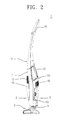
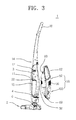
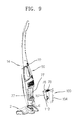
- FIGS. 1 and 2 are a front view and a right side view showing a hand-held and stick vacuum cleaner 1 according to an exemplary embodiment of the present disclosure, respectively, and FIG. 3 is an exploded perspective view showing the hand-held and stick vacuum cleaner 1 in which a hand-held cleaner unit 50 is separated from a stick body 14.
- the hand-held and stick vacuum cleaner 1 includes a stick body 14, a nozzle assembly 2 and a hand-held cleaner unit 50.
- the stick body 14 is divided into a handle 16 provided on an upper part thereof and a central part 11 in the form of a jar having a mounting space 3 provided on a lower part thereof.
- the handle 16 as a portion coupled to an upper end of the central part 11, is a portion, which is gripped by the user, so that she or he can push or pull the nozzle assembly 2 when using the hand-held and stick cleaner 1.
- the mounting space 3 formed in the central part 11 is a space, which can mount or separate the hand-held cleaner unit 50 in or from the stick body 14.
- FIG. 1 is a view showing a front part of the stick body 14.
- the front part of the stick body 14 is a side of the stick body 14, which is viewed from a direction of arrow A
- a rear part of the stick body 14 is a side of the stick body 14, which is viewed from a direction of arrow B.
- a body discharge part 20 which is made up of a plurality of discharge holes, is formed in the front part of the stick body 14, and a body-transparent part 18, which is made of a transparent panel, is formed below the body discharge part 20.
- the nozzle assembly 2 is rotatably coupled to a lower end of the stick body 14, and an inner air passage 7 (see FIG. 5 ) in the nozzle assembly 2 is communicated with a neck part 6 and an opening 4 of the stick body 14. Accordingly, an external air and a dust or dirt drawn in through the nozzle assembly 2 are flowed into the hand-held cleaner unit 50 through the neck part 6 and the opening 4 of the stick body 14.
- the nozzle assembly 2 has a bottom inlet port 2a for drawing in the air from a surface to be cleaned formed in a lower surface thereof and a cylindrical brush 3 for brushing off the dust or dirt from the surface to be cleaned rotatably disposed therein (see FIG. 5 ).
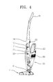
- FIG. 4 is a perspective view showing the hand-held and stick vacuum cleaner 1 according to the exemplary embodiment of the present disclosure in a state where the hand-held cleaner unit 50 is mounted in the stick body 14
- FIG. 5 is a cross-sectional view showing the hand-held and stick vacuum cleaner 1 according to the exemplary embodiment of the present disclosure
- FIG. 6 is a partial view showing a modified stick body 14' in order to explain a structure that a wheel 28 is disposed on a housing 25 of a body connecting terminal 24 on a lower end of the rear part of the stick body 14'.
- a first connecting terminal 12 is provided in the mounting space 3 of the stick body 14 according to the exemplary embodiment of the present disclosure, and a second connecting terminal 60 is disposed on the rear part of the hand-held cleaner unit 50. If the hand-held cleaner unit 50 is mounted in the mounting space 3, the first and the second connecting terminals 12 and 60 come in contact with or to each other and thus the stick body 14 and the hand-held cleaner unit 50 are electrically connected.
- a reference number 22 is a locking button for fixing or separating the hand-held cleaner unit 50 in or from the mounting space 3.
- the stick body 14 at a lower end of the rear part thereof has a body connecting terminal 24 disposed to connect with a charger terminal 82 (see FIG. 7 ) and a housing 26 configured to surround or wrap the body connecting terminal 24 thus to prevent the body connecting terminal 24 from being contaminated.
- a stick body 14' shown in FIG. 6 has the same structure as that of the stick body 14 according to the exemplary embodiment of the present disclosure shown in FIGS. 1 to 4 , except that the wheel 28 is disposed on the housing 26.
- the wheel 28 is disposed on an outer surface of the housing 26, and when the user grips the handle 16 and lays down the stick body 14', rotates while being in contact with the surface to be cleaned thus to allow the stick body 14' to be easily moved and at the same time, to be supported.
- the wheel 28 restricts a rotation range of the stick body 14', so that other portions of the stick body 14' does not come in direct contact with the surface to be cleaned, thereby preventing the stick body 14' from being damaged due to excessive rotation thereof.
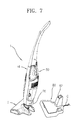
- FIG. 7 is a perspective view showing the hand-held and stick vacuum cleaner 1 and a charger 80. If the hand-held stick vacuum cleaner 1 is mounted on the charger 80, the body connecting terminal 24 is inserted into and connected to the charger terminal 82 of the charger 80. When the body connecting terminal 24 is connected to the charger terminal 82, a commercial electric power is applied to the body connecting terminal 24 through an electric wire C, and the applied electric power charges a battery (not shown) disposed in the hand-held cleaner unit 50 through the first connecting terminal 12 (the first connecting terminal 12 and the second connecting terminal 60 of the hand-held cleaner unit 50 are connected with or to each other while coming in contact therewith in a state where the hand-held cleaner unit 50 is mounted in the mounting space 3 as shown in FIG. 8 ).
- a battery not shown
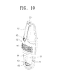
- the hand-held cleaner unit 50 includes a body 52 and a cyclone dust collecting apparatus 100.
- a first discharge part 56 in the form of a grill having a plurality of discharge holes, a handle 62 and a power button 65.
- a vacuum source M (see FIG. 5 ) for generating a suction force and the battery (not shown) are mounted in an upper part of the body 52.
- a second discharge part 58 (see FIG. 3 ) in the form of a grill having a plurality of discharge holes is formed at a position opposite to that of the first discharge part 56.
- the second connecting terminal 60 is disposed on an upper part of the second discharge part 58.
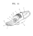
- a roller 114 (see FIG.
- a cyclone mounting space 51 in which the cyclone dust collecting apparatus 100 is mounted is penetrated through and formed in the lower part of the body 52.
- the body 52 further includes a cleaner inlet port 63, the roller 114, an inlet gasket 63', an outlet gasket 67, and a rib 69.
- the cleaner inlet port 63 is coupled with the opening 4 of the stick body 14 and a cyclone inlet 110 (see FIGS. 5 and 13 ) while being in tight contact therewith.
- the inlet gasket 63' is disposed on a circumferential surface of the cleaner inlet port 63 to prevent an air from being leaked through coupled portions of the cleaner inlet port 63 and the cyclone inlet 110 (see FIGS. 5 and 13 ).
- the outlet gasket 67 is disposed around a motor inlet port M' formed on an upper part of the cyclone mounting space 51 to increase a contact force of coupled portions between a pre-motor filter unit 70 and the body 52 thus to prevent an air from being leaked therethrough.
- the roller 114 is disposed on a lower part of the cleaner inlet port 63, and when the hand-held cleaner unit 50 is used being separated from the stick body 14, rotates while being in contact with the surface to be cleaned thus to allow the hand-held cleaner unit 50 to easily move back and forth and to reduce friction between the surface to be cleaned and the hand-held cleaner unit 50.
- the rib 69 is formed on and projected from the cleaner inlet port 63, and when the hand-held cleaner unit 50 is mounted in the mounting space 3, is inserted into the opening 4 of the stick body 14 to prevent an air from being leaked between the cleaner inlet port 63 and the opening 4.
- the rib 69 reduces a separated space between the surface to be cleaned and the cleaner inlet port 63 to allow the suction force of the vacuum source M to be transmitted to the surface to be cleaned well, thereby improving dust suction performance of the hand-held cleaner unit 50 to the surface to be cleaned.
- the cyclone dust collecting apparatus 100 includes a dust collecting bin 102, a cover member 104, a pre-motor filter unit 70 and a cyclone bin 107.
- the dust collecting bin 102 is made of a transparent material and has an approximately rectangle shape.
- the pre-motor filter unit 70 is detachably mounted on a side of the duct collecting bin 102.
- the cover member 104 is made of a transparent material and integrally formed with the dust collecting bin 102.
- the cover member 104 forms an outer surface of the hand-held cleaner unit 50 when the cyclone dust collecting apparatus 100 is mounted in the cyclone mounting space 51 of the hand-held cleaner unit 50.
- a pair of locking members 113 On both side ends of the cover member 104 is disposed a pair of locking members 113, which is able to be hinged and elastically supported by springs (not shown).
- the user can push the pair of locking members 113 with her or his one hand to lock or release them in or from locking grooves 77 (see FIG. 10 ) formed on both sides of the cyclone mounting space 51 of the body 52, thereby assembling or separating the cyclone dust collecting apparatus 100 in or from the body 52.
- the dust collecting bin 102 and the cover member 104 are transparent, the user can check the amount of dust collected in the dust collecting bin 102 or the operation state of the cyclone dust collecting apparatus 100 with her or his eyes from the outside. Even when the cyclone dust collecting apparatus 100 is mounted in the cyclone mounting space 51 (see FIG. 10 ), the user can see the inside of the cyclone dust collecting apparatus 100 from the front part and the rear part of the hand-held cleaner unit 50.
- the hand-held cleaner unit 50 is mounted in the stick body 14, as shown in FIG. 1 , the user can see the inside of the cyclone dust collecting apparatus 100 through a front part of a hand-held and stick vacuum cleaner 1. In other words, through the body-transparent part 18 of the stick body 14, the user can check the inside of the cyclone dust collecting apparatus 100 with her or his eyes.
- the user can see the inside of the cyclone dust collecting apparatus 100 through a rear part of the hand-held and stick vacuum cleaner 1.
- the user can check the inside of the cyclone dust collecting apparatus 100 through the rear part (the arrow B in FIG. 2 ) of the hand-held and stick vacuum cleaner 1 even if she or he does not move in front of the hand-held and stick vacuum cleaner 1.
- the cyclone bin 107 is disposed in the dust collecting bin 102 to divide an inner space of the dust collecting bin 102 into a centrifugal chamber S1 and a dust accommodating chamber S2 (see FIG. 5 ).
- a central pipe 108 is provided in a center of the cyclone bin 107, and a spiral flow path-guide member 106 for inducing a rotation of air drawn in through a cyclone inlet 110 is disposed between the cyclone bin 107 and the central pipe 108.
- the pre-motor filter unit 70 is disposed to be coupled to an upper part of the dust collecting bin 102, and includes an upper casing 76, a lower casing 72, and a filter member 74.
- a grill 71 is convexly projected from the lower casing 72, and a plurality of air holes 78 for discharge the air is formed in the upper casing 76.
- the filter member 74 is mounted between the upper casing 76 and the lower casing 72.
- the convex grill 71 allows the air to maintain a whirling force in an upper part of the cyclone bin 107, and first filters a relatively large dust or dirt from the air discharged from the centrifugal chamber S1. Further, the filter member 74 secondly separates a fine dust or dirt from the air past the grill 71.
- the pre-motor filter unit 70 along with the cyclone duct collecting apparatus 100 is separated therefrom.
- the user should separate the pre-motor filter unit 70 from the cyclone duct collecting apparatus 100.
- she or he can naturally check contamination levels of the pre-motor filter unit 70 and timely replace the filter member 74 with a new one.
- the cyclone inlet 110 is formed in a lower surface of the dust collecting bin 102 to come in tight contact with the cleaner inlet port 63, and has a semicircle shape.
- an anti-back flow rib 112 is projected toward the inside of the dust collecting bin 102.
- the anti-back flow rib 112 is illustrated as being provided on a portion of a circumference of the cyclone inlet 110, it may be formed on the entire circumference of the cyclone inlet 110 to project to a certain distance into the cyclone bin 107 therefrom.
- the anti-back flow rib 112 acts to prevent the dust or dirt remained in the cyclone bin 107 from flowing out through the cyclone inlet 110.
- the central pipe 108 and the flow path-guide member 106 are disposed in the cyclone bin 107.
- the flow path-guide member 106 has a spiral shape, and is disposed between an outer surface of the central pipe 108 and an inner surface of the cyclone bin 107.
- the air drawn in through the cyclone inlet 110 rides on the flow path-guide member 106 and rotates while forming the whirling current to separate the dust or dirt therefrom.
- the user mounts the hand-held cleaner unit 50 in the stick body 14 in order to use the hand-held and stick cleaner (hereinafter, referred as 'stick type cleaning'), she or he pushes a power switch 9 disposed on the stick body 14 to operate the hand-held and stick vacuum cleaner 1, and then grips the handle 16 of the stick body 14 with her or his hand and uses the stick body 14, tilting the stick body 14 to the nozzle assembly 2.
- 'stick type cleaning' she or he pushes a power switch 9 disposed on the stick body 14 to operate the hand-held and stick vacuum cleaner 1
- the handle 16 of the stick body 14 with her or his hand and uses the stick body 14, tilting the stick body 14 to the nozzle assembly 2.
- the modified stick body 14' as shown in FIG.
- an external air laden with a dust or dirt is flowed into the cyclone dust collecting apparatus 100 via the nozzle assembly 2, the neck part 6 and the opening 4 of the stick body 14.
- the external air that flows into the cyclone dust collecting apparatus 100 whirls in the centrifugal chamber S1, and the dust or dirt included in the external air is separated from the external air by the whirling centrifugal force and stored in the dust collecting bin 102.
- the air from which the dust or di rt is separated passes through the pre-motor filter unit 70 to remove a fine dust or dirt therefrom by means of the grill 71 and the filter member 74, and then is discharged to the first and the second discharge parts 56 and 58 of the hand-held cleaner unit 50 via the vacuum source M.
- the air discharged to the second discharge part 58 is discharged to the front part of the stick body 14 through the body discharge part 20.
- the user can separate the hand-held cleaner unit 50 from the rear part of the stick body 14 to clean the surface to be cleaned by using only the hand-held cleaner unit 50 (hereinafter, referred as 'hand-held type cleaning').
- the user turns on/off the vacuum source M disposed in the body 52 by using the power button 65 disposed on the body 52.
- the user can move the hand-held cleaner unit 50 while bringing the cleaner inlet port 63 and the roller 114 (see FIG. 11 ) to be in contact with the surface to be cleaned.
- the operation of the hand-held cleaner unit 50 allows the external air to flow into the cyclone dust collecting apparatus 100 through the cleaner inlet port 63 and the cyclone inlet 110.
- a dust collecting operation in the cyclone dust collecting apparatus 100 is the same as that in the stick type cleaning.
- the air from which the dust or dirt is separated in the cyclone dust collecting apparatus 100 is discharged to the first and the second discharge parts 56 and 58 through the pre-motor filter unit 70 and the vacuum source M.
- the user pushes or pulls the hand-held and stick cleaner 1 to clean the surface to be cleaned while being positioned to the rear part thereof when carrying out the stick type cleaning.
- the user wants to change the cleaning work form from the stick type cleaning to the hand-held type cleaning, she or he only conveniently and quickly separate the hand-held cleaner unit 50 from the rear part of the stick body 14 and then carry out the hand-held type cleaning by using the separated hand-held cleaner unit 50 in a posture for the stick type cleaning without moving to the front part of the stick body 14.
- the hand-held and stick cleaner 1 of the exemplary embodiment of the disclosure has the body discharge part 20 provided in the front part of the stick body 14 and the first connecting terminal 12 provided on the rear part of the stick body 14. Further, the first discharge part 56 is provided in the front part of the hand-held cleaner unit 50 and the second discharge part 58 and the second connecting terminal 60 are provided at the rear part of the hand-held cleaner unit 50. Accordingly, if the hand-held cleaner unit 50 is mounted in the mounting unit 3, the second discharge part 58 is communicated with the body discharge part 20, so that the air discharged to the second discharge part 58 is discharged to the front part of the stick body 14 through the body discharge part 20. Also, the first and the second connecting terminals 12 and 60 are coupled with or to each other and thus the stick body 14 and the hand-held cleaner unit 50 are electrically connected.
- the dust collecting bin 102 and the cover member 104 of the cyclone dust collecting apparatus 100 is made of the transparent material and the body-transparent part 18 is also provided in the front part of the stick body 14. Accordingly, a visibility to the inside of the dust collecting bin 102 is improved, thereby allowing the user to easily check the operation state of the cleaner. In other words, even when the hand-held cleaner unit 50 is mounted in the mounting space 3, the user can check the operation state of the cyclone dust collecting apparatus 100 and the collected dust or dirt state in the dust collecting bin 102 through the front part and the rear part of the stick body 14.
- the user which carries out the cleaning work at the rear part of the hand-held and cleaner 1, can check the collected dust or dirt state in the dust collecting bin 102 with her or his eyes from the rear part of the hand-held and stick vacuum cleaner 1 even if she or he does not move to the front part of the hand-held and stick vacuum cleaner 1.
- the body con necting terminal 24 disposed on the rear part of the stick body 14 has the structure that it is disposed in the housing 26, that is, the structure that it is surrounded or wrapped by the housing 26, thereby allowing it to reduce pollution in the use or the storing of the cleaner and thus to prevent a short circuit, a poor charge or the like due to the pollution.
- the wheel 28 may be disposed on the outer surface of the housing surrounding the body connecting terminal 24, so that it allows the hand-held and cleaner 1 to easily move and restricts the rotation range of the stick body 14', thereby preventing the stick body 14' from being damaged due to excessive rotation thereof.
- the cyclone dust collecting apparatus 100 is configured, so that the cyclone inlet 110 is formed on the lower surface of the dust collecting bin 102 and the pre-motor filter unit 70 including the grill 71 opposite to the cyclone inlet 110 is detachably disposed on the upper end of the dust collecting bin 102, thereby preventing a flowing direction of air from being excessively changed in the cyclone dust collecting apparatus 100.
- the flowing direction of air is not sharply curved or converted at an angle of 180°, and the air flow is in a straight line except that it rotates. Accordingly, in the cyclone dust collecting apparatus 100, a loss in pressure is reduced and a dust collecting efficiency is improved.
- the anti-back flow rib 112 is internally projected and disposed in the cyclone inlet 110, thereby preventing the dust or dirt in the cyclone bin 107 from flowing backward through the cyclone inlet 110 and thus allowing convenience for use to improve.
Applications Claiming Priority (2)
| Application Number | Priority Date | Filing Date | Title |
|---|---|---|---|
| US34993810P | 2010-05-31 | 2010-05-31 | |
| KR1020100095024A KR101224595B1 (ko) | 2010-05-31 | 2010-09-30 | 핸디-스틱형 진공청소기 |
Publications (3)
| Publication Number | Publication Date |
|---|---|
| EP2392244A2 true EP2392244A2 (fr) | 2011-12-07 |
| EP2392244A3 EP2392244A3 (fr) | 2013-07-10 |
| EP2392244B1 EP2392244B1 (fr) | 2017-01-18 |
Family
ID=44508699
Family Applications (1)
| Application Number | Title | Priority Date | Filing Date |
|---|---|---|---|
| EP11167785.2A Active EP2392244B1 (fr) | 2010-05-31 | 2011-05-27 | Aspirateur portatif de type bâton |
Country Status (2)
| Country | Link |
|---|---|
| US (1) | US8671510B2 (fr) |
| EP (1) | EP2392244B1 (fr) |
Cited By (4)
| Publication number | Priority date | Publication date | Assignee | Title |
|---|---|---|---|---|
| WO2014001496A1 (fr) * | 2012-06-29 | 2014-01-03 | BSH Bosch und Siemens Hausgeräte GmbH | Aspirateur pourvu d'un cyclone |
| WO2014001489A1 (fr) * | 2012-06-29 | 2014-01-03 | BSH Bosch und Siemens Hausgeräte GmbH | Combinaison d'un mini-aspirateur et d'un boîtier d'aspirateur ainsi que mini-aspirateur et boîtier d'aspirateur |
| WO2014001502A1 (fr) * | 2012-06-29 | 2014-01-03 | BSH Bosch und Siemens Hausgeräte GmbH | Combinaison composée d'un mini-aspirateur et d'un bâti d'aspirateur-balai, ainsi que mini-aspirateur et bâti d'aspirateur-balai |
| US10758101B2 (en) | 2017-06-12 | 2020-09-01 | Emerson Electric Co. | Upright vacuum cleaner with battery support plate |
Families Citing this family (74)
| Publication number | Priority date | Publication date | Assignee | Title |
|---|---|---|---|---|
| US8950039B2 (en) | 2009-03-11 | 2015-02-10 | G.B.D. Corp. | Configuration of a surface cleaning apparatus |
| US20210401246A1 (en) | 2016-04-11 | 2021-12-30 | Omachron Intellectual Property Inc. | Surface cleaning apparatus |
| US9888817B2 (en) | 2014-12-17 | 2018-02-13 | Omachron Intellectual Property Inc. | Surface cleaning apparatus |
| US10258208B2 (en) | 2016-04-11 | 2019-04-16 | Omachron Intellectual Property Inc. | Surface cleaning apparatus |
| US10722086B2 (en) | 2017-07-06 | 2020-07-28 | Omachron Intellectual Property Inc. | Handheld surface cleaning apparatus |
| US20120030898A1 (en) * | 2010-08-05 | 2012-02-09 | James Todd Crouch | Hand-held vacuum cleaner with resilient rubber flap valve |
| US9962052B2 (en) | 2011-03-04 | 2018-05-08 | Omachron Intellectual Property Inc. | Surface cleaning apparatus |
| US20120222252A1 (en) * | 2011-03-04 | 2012-09-06 | G.B.D. Corp. | Surface cleaning apparatus |
| USD693068S1 (en) * | 2012-02-02 | 2013-11-05 | Foshan Shunde Xinshengyuan Electrical Applicances Co., Ltd. | Pet hair dryer |
| CN102613940A (zh) * | 2012-03-31 | 2012-08-01 | 江苏美的春花电器股份有限公司 | 立式吸尘器及其灰尘分离装置 |
| DE102012206624A1 (de) * | 2012-04-23 | 2013-10-24 | Robert Bosch Gmbh | System mit einem Bodenstaubsauger und einem Handstaubsauger |
| DE102012211246A1 (de) * | 2012-06-29 | 2014-01-02 | BSH Bosch und Siemens Hausgeräte GmbH | Kombination aus einem Kleinsauger und einem Stielsaugerrahmen sowie Kleinsauger und Stielsaugerrahmen |
| US9516979B2 (en) * | 2013-11-21 | 2016-12-13 | Sharkninja Operating Llc | Surface cleaning apparatus configurable in a storage position |
| JP6117128B2 (ja) * | 2014-02-20 | 2017-04-19 | 日立アプライアンス株式会社 | 電気掃除機 |
| EP3125736B1 (fr) | 2014-04-04 | 2018-06-13 | Techtronic Industries Company Limited | Aspirateur |
| US9420925B2 (en) | 2014-07-18 | 2016-08-23 | Omachron Intellectual Property Inc. | Portable surface cleaning apparatus |
| US9451853B2 (en) | 2014-07-18 | 2016-09-27 | Omachron Intellectual Property Inc. | Portable surface cleaning apparatus |
| US9314139B2 (en) | 2014-07-18 | 2016-04-19 | Omachron Intellectual Property Inc. | Portable surface cleaning apparatus |
| US9585530B2 (en) * | 2014-07-18 | 2017-03-07 | Omachron Intellectual Property Inc. | Portable surface cleaning apparatus |
| US10244907B2 (en) * | 2014-08-25 | 2019-04-02 | Lg Electronics Inc. | Cleaning apparatus |
| US9439548B2 (en) | 2014-10-16 | 2016-09-13 | Techtronic Industries Co. Ltd. | Battery removal for a vacuum cleaner |
| US11445872B2 (en) | 2014-12-17 | 2022-09-20 | Omachron Intellectual Property Inc. | Surface cleaning apparatus |
| US10136778B2 (en) * | 2014-12-17 | 2018-11-27 | Omachron Intellectual Property Inc. | Surface cleaning apparatus |
| US11534041B2 (en) | 2014-12-17 | 2022-12-27 | Omachron Intellectual Property Inc. | Surface cleaning apparatus |
| US11452409B2 (en) | 2014-12-17 | 2022-09-27 | Omachron Intellectual Property Inc. | Surface cleaning apparatus |
| US11445871B2 (en) | 2014-12-17 | 2022-09-20 | Omachron Intellectual Property Inc. | Surface cleaning apparatus |
| US10251519B2 (en) * | 2014-12-17 | 2019-04-09 | Omachron Intellectual Property Inc. | Surface cleaning apparatus |
| US11950745B2 (en) | 2014-12-17 | 2024-04-09 | Omachron Intellectual Property Inc. | Surface cleaning apparatus |
| US9883781B2 (en) | 2014-12-17 | 2018-02-06 | Omachron Intellectual Property Inc. | All in the head surface cleaning apparatus |
| US10022027B2 (en) | 2014-12-17 | 2018-07-17 | Omachron Intellectual Property Inc. | All in the head surface cleaning apparatus |
| USD785265S1 (en) * | 2015-02-23 | 2017-04-25 | Sharkninja Operating Llc | Floor cleaner |
| USD765332S1 (en) * | 2015-06-16 | 2016-08-30 | Sharkninja Operating Llc | Floor cleaning device |
| GB2542385B (en) | 2015-09-17 | 2018-10-10 | Dyson Technology Ltd | Vacuum Cleaner |
| GB2542387B (en) | 2015-09-17 | 2017-11-01 | Dyson Technology Ltd | Vacuum cleaner |
| GB2542386B (en) | 2015-09-17 | 2018-10-10 | Dyson Technology Ltd | Vacuum Cleaner |
| CN105249891B (zh) | 2015-11-03 | 2018-01-30 | 莱克电气股份有限公司 | 一种三级龙卷风尘杯过滤系统及包含该系统的吸尘器 |
| US10080471B2 (en) | 2015-12-21 | 2018-09-25 | Electrolux Home Care Products, Inc. | Versatile vacuum cleaners |
| EP3238588A4 (fr) * | 2016-01-20 | 2018-05-30 | Jiangsu Midea Cleaning Appliances Co., Ltd. | Aspirateur |
| WO2017124628A1 (fr) * | 2016-01-20 | 2017-07-27 | 江苏美的清洁电器股份有限公司 | Aspirateur portatif |
| CA2971319A1 (fr) * | 2016-01-20 | 2017-07-27 | Jiangsu Midea Cleaning Appliances Co., Ltd. | Aspirateur |
| EP3406172B1 (fr) * | 2016-01-20 | 2023-05-03 | Jiangsu Midea Cleaning Appliances Co., Ltd. | Aspirateur |
| WO2017124633A1 (fr) * | 2016-01-20 | 2017-07-27 | 江苏美的清洁电器股份有限公司 | Aspirateur |
| US10016105B2 (en) | 2016-04-11 | 2018-07-10 | Omachron Intellectual Property Inc. | Surface cleaning apparatus |
| CN109310254B (zh) * | 2016-04-11 | 2021-08-27 | 奥马克罗知识产权有限公司 | 表面清洁装置 |
| US11241129B2 (en) | 2016-04-11 | 2022-02-08 | Omachron Intellectual Property Inc. | Surface cleaning apparatus |
| US10568477B2 (en) | 2016-04-11 | 2020-02-25 | Omachron Intellectual Property Inc. | Surface cleaning apparatus |
| US10016104B2 (en) | 2016-04-11 | 2018-07-10 | Omachron Intellectual Property Inc. | Surface cleaning apparatus |
| US9986880B2 (en) | 2016-04-11 | 2018-06-05 | Omachron Intellectual Property Inc. | Surface cleaning apparatus |
| USD813475S1 (en) | 2016-06-01 | 2018-03-20 | Milwaukee Electric Tool Corporation | Handheld vacuum cleaner |
| CN109803568B (zh) * | 2016-10-07 | 2021-09-10 | 伊莱克斯公司 | 过滤器改进的杆式真空吸尘器 |
| US11445878B2 (en) * | 2020-03-18 | 2022-09-20 | Omachron Intellectual Property Inc. | Surface cleaning apparatus with removable air treatment member assembly |
| US10537216B2 (en) | 2017-07-06 | 2020-01-21 | Omachron Intellectual Property Inc. | Handheld surface cleaning apparatus |
| US11745190B2 (en) | 2019-01-23 | 2023-09-05 | Omachron Intellectual Property Inc. | Surface cleaning apparatus |
| US10631693B2 (en) | 2017-07-06 | 2020-04-28 | Omachron Intellectual Property Inc. | Handheld surface cleaning apparatus |
| US11666193B2 (en) * | 2020-03-18 | 2023-06-06 | Omachron Intellectual Property Inc. | Surface cleaning apparatus with removable air treatment member assembly |
| US10702113B2 (en) | 2017-07-06 | 2020-07-07 | Omachron Intellectual Property Inc. | Handheld surface cleaning apparatus |
| US11730327B2 (en) * | 2020-03-18 | 2023-08-22 | Omachron Intellectual Property Inc. | Surface cleaning apparatus with removable air treatment assembly |
| US10750913B2 (en) | 2017-07-06 | 2020-08-25 | Omachron Intellectual Property Inc. | Handheld surface cleaning apparatus |
| US10506904B2 (en) | 2017-07-06 | 2019-12-17 | Omachron Intellectual Property Inc. | Handheld surface cleaning apparatus |
| US10842330B2 (en) | 2017-07-06 | 2020-11-24 | Omachron Intellectual Property Inc. | Handheld surface cleaning apparatus |
| USD897059S1 (en) * | 2017-10-20 | 2020-09-22 | Shenzhen Hizero Technologies Co., Ltd. | Floor cleaner |
| KR20210019053A (ko) | 2018-06-22 | 2021-02-19 | 비쎌 인코포레이티드 | 표면 청소 장치 및 트레이 |
| WO2020015251A1 (fr) * | 2018-07-18 | 2020-01-23 | 江苏美的清洁电器股份有限公司 | Dispositif de nettoyage portatif et ensemble de traitement de l'air |
| US11013384B2 (en) | 2018-08-13 | 2021-05-25 | Omachron Intellectual Property Inc. | Cyclonic air treatment member and surface cleaning apparatus including the same |
| US11192122B2 (en) | 2018-08-13 | 2021-12-07 | Omachron Intellectual Property Inc. | Cyclonic air treatment member and surface cleaning apparatus including the same |
| US11006799B2 (en) | 2018-08-13 | 2021-05-18 | Omachron Intellectual Property Inc. | Cyclonic air treatment member and surface cleaning apparatus including the same |
| DE212019000449U1 (de) * | 2018-12-13 | 2021-07-21 | Koki Holdings Co., Ltd. | Reiniger |
| USD937513S1 (en) | 2019-09-16 | 2021-11-30 | Techtronic Cordless Gp | Floor cleaner |
| WO2021138179A1 (fr) * | 2020-01-03 | 2021-07-08 | Techtronic Cordless Gp | Ensemble aspirateur |
| WO2021138122A1 (fr) | 2020-01-03 | 2021-07-08 | Techtronic Cordless Gp | Adaptateur pour ensemble aspirateur |
| EP4120883A4 (fr) | 2020-03-18 | 2024-03-27 | Omachron Intellectual Property Inc | Appareil de nettoyage de surface avec ensemble élément de traitement d'air amovible |
| USD988624S1 (en) * | 2020-12-29 | 2023-06-06 | Wuhan Dishui Intelligent Technology Co., Ltd. | Hand-held scrubber |
| US11779178B2 (en) | 2021-08-05 | 2023-10-10 | Omachron Intellectual Property Inc. | Household appliance having an improved cyclone and a cyclone for same |
| CN117502958A (zh) * | 2022-07-29 | 2024-02-06 | 莱克电气股份有限公司 | 一种地面吸尘、地面清洗、手持吸尘三合一多功能吸尘器 |
Citations (1)
| Publication number | Priority date | Publication date | Assignee | Title |
|---|---|---|---|---|
| WO2008088278A2 (fr) | 2007-01-19 | 2008-07-24 | Aktiebolaget Electrolux | Améliorations apportées à des pertes de pression d'air dans un aspirateur |
Family Cites Families (10)
| Publication number | Priority date | Publication date | Assignee | Title |
|---|---|---|---|---|
| DE8814124U1 (fr) | 1988-11-11 | 1989-01-05 | Ringler, Bernhard, 7076 Waldstetten, De | |
| US5819364A (en) | 1992-09-09 | 1998-10-13 | Pentalpha Enterprises, Ltd. | Detachable handle accessory for a portable steam vacuum cleaner |
| JP3744580B2 (ja) | 1996-01-31 | 2006-02-15 | 三洋電機株式会社 | 電気掃除機 |
| JP3435353B2 (ja) | 1998-07-30 | 2003-08-11 | 株式会社日立製作所 | ハンディタイプ電気掃除機 |
| SE0300355D0 (sv) | 2003-02-10 | 2003-02-10 | Electrolux Ab | Hand held vacuum cleaner |
| US20070136984A1 (en) | 2005-12-15 | 2007-06-21 | Zweita International Co., Ltd. | Rechargeable vacuum cleaner |
| US20070163075A1 (en) | 2006-01-17 | 2007-07-19 | Butler Dennis C | Stair cleaning vacuum cleaner |
| KR100776402B1 (ko) | 2007-02-05 | 2007-11-16 | 삼성광주전자 주식회사 | 필터조립체를 구비한 멀티 사이클론 분리장치 |
| KR20080102647A (ko) | 2007-05-21 | 2008-11-26 | 삼성광주전자 주식회사 | 진공청소기용 사이클론 집진유닛 |
| US8062398B2 (en) | 2008-12-19 | 2011-11-22 | Bissell Homecare, Inc. | Vacuum cleaner and cyclone module therefor |
-
2011
- 2011-05-26 US US13/067,364 patent/US8671510B2/en active Active
- 2011-05-27 EP EP11167785.2A patent/EP2392244B1/fr active Active
Patent Citations (1)
| Publication number | Priority date | Publication date | Assignee | Title |
|---|---|---|---|---|
| WO2008088278A2 (fr) | 2007-01-19 | 2008-07-24 | Aktiebolaget Electrolux | Améliorations apportées à des pertes de pression d'air dans un aspirateur |
Cited By (4)
| Publication number | Priority date | Publication date | Assignee | Title |
|---|---|---|---|---|
| WO2014001496A1 (fr) * | 2012-06-29 | 2014-01-03 | BSH Bosch und Siemens Hausgeräte GmbH | Aspirateur pourvu d'un cyclone |
| WO2014001489A1 (fr) * | 2012-06-29 | 2014-01-03 | BSH Bosch und Siemens Hausgeräte GmbH | Combinaison d'un mini-aspirateur et d'un boîtier d'aspirateur ainsi que mini-aspirateur et boîtier d'aspirateur |
| WO2014001502A1 (fr) * | 2012-06-29 | 2014-01-03 | BSH Bosch und Siemens Hausgeräte GmbH | Combinaison composée d'un mini-aspirateur et d'un bâti d'aspirateur-balai, ainsi que mini-aspirateur et bâti d'aspirateur-balai |
| US10758101B2 (en) | 2017-06-12 | 2020-09-01 | Emerson Electric Co. | Upright vacuum cleaner with battery support plate |
Also Published As
| Publication number | Publication date |
|---|---|
| EP2392244B1 (fr) | 2017-01-18 |
| US8671510B2 (en) | 2014-03-18 |
| US20110289719A1 (en) | 2011-12-01 |
| EP2392244A3 (fr) | 2013-07-10 |
Similar Documents
| Publication | Publication Date | Title |
|---|---|---|
| EP2392244B1 (fr) | Aspirateur portatif de type bâton | |
| US11484164B2 (en) | Cyclone dust collecting apparatus and handheld cleaner having the same | |
| KR101224595B1 (ko) | 핸디-스틱형 진공청소기 | |
| EP1629758B1 (fr) | Unité collecteur de poussière pour aspirateur | |
| EP2189096A2 (fr) | Appareil dépoussiérant et nettoyeur l'utilisant | |
| JP2010508885A (ja) | ハンディ型真空掃除機 | |
| US20090276974A1 (en) | Cordless Hand-Held Rechargeable Vacuum Cleaner and Charger Unit Therefore | |
| JP2022125218A (ja) | 電気掃除機 | |
| CN112074220B (zh) | 清洁器 | |
| CN111655102B (zh) | 清洁器 | |
| CN111436856B (zh) | 电动吸尘器 | |
| KR20120014326A (ko) | 업라이트형 진공청소기 | |
| JP6754406B2 (ja) | 電気掃除機 | |
| CN111818834B (zh) | 电动吸尘器 | |
| KR100762326B1 (ko) | 핸디청소기 일체형 진공청소기 | |
| JP2023024828A (ja) | 電気掃除機セット | |
| JP2023013280A (ja) | 電気掃除機 | |
| KR100762325B1 (ko) | 핸디청소기 및 이를 구비하는 진공청소기 | |
| JP2020110681A (ja) | 電気掃除機 | |
| CN115211752A (zh) | 手持吸尘器 | |
| CN116507255A (zh) | 吸尘器 | |
| CN115103618A (zh) | 电动吸尘器的吸口体以及具备该吸口体的电动吸尘器 |
Legal Events
| Date | Code | Title | Description |
|---|---|---|---|
| AK | Designated contracting states |
Kind code of ref document: A2 Designated state(s): AL AT BE BG CH CY CZ DE DK EE ES FI FR GB GR HR HU IE IS IT LI LT LU LV MC MK MT NL NO PL PT RO RS SE SI SK SM TR |
|
| AX | Request for extension of the european patent |
Extension state: BA ME |
|
| PUAI | Public reference made under article 153(3) epc to a published international application that has entered the european phase |
Free format text: ORIGINAL CODE: 0009012 |
|
| RAP1 | Party data changed (applicant data changed or rights of an application transferred) |
Owner name: SAMSUNG ELECTRONICS CO., LTD. |
|
| PUAL | Search report despatched |
Free format text: ORIGINAL CODE: 0009013 |
|
| AK | Designated contracting states |
Kind code of ref document: A3 Designated state(s): AL AT BE BG CH CY CZ DE DK EE ES FI FR GB GR HR HU IE IS IT LI LT LU LV MC MK MT NL NO PL PT RO RS SE SI SK SM TR |
|
| AX | Request for extension of the european patent |
Extension state: BA ME |
|
| RIC1 | Information provided on ipc code assigned before grant |
Ipc: A47L 5/24 20060101AFI20130605BHEP Ipc: A47L 5/28 20060101ALI20130605BHEP Ipc: A47L 5/22 20060101ALI20130605BHEP |
|
| 17P | Request for examination filed |
Effective date: 20140110 |
|
| RBV | Designated contracting states (corrected) |
Designated state(s): AL AT BE BG CH CY CZ DE DK EE ES FI FR GB GR HR HU IE IS IT LI LT LU LV MC MK MT NL NO PL PT RO RS SE SI SK SM TR |
|
| GRAP | Despatch of communication of intention to grant a patent |
Free format text: ORIGINAL CODE: EPIDOSNIGR1 |
|
| INTG | Intention to grant announced |
Effective date: 20160809 |
|
| GRAS | Grant fee paid |
Free format text: ORIGINAL CODE: EPIDOSNIGR3 |
|
| GRAA | (expected) grant |
Free format text: ORIGINAL CODE: 0009210 |
|
| AK | Designated contracting states |
Kind code of ref document: B1 Designated state(s): AL AT BE BG CH CY CZ DE DK EE ES FI FR GB GR HR HU IE IS IT LI LT LU LV MC MK MT NL NO PL PT RO RS SE SI SK SM TR |
|
| REG | Reference to a national code |
Ref country code: GB Ref legal event code: FG4D |
|
| REG | Reference to a national code |
Ref country code: CH Ref legal event code: EP |
|
| REG | Reference to a national code |
Ref country code: AT Ref legal event code: REF Ref document number: 862389 Country of ref document: AT Kind code of ref document: T Effective date: 20170215 |
|
| REG | Reference to a national code |
Ref country code: IE Ref legal event code: FG4D |
|
| REG | Reference to a national code |
Ref country code: DE Ref legal event code: R096 Ref document number: 602011034423 Country of ref document: DE |
|
| REG | Reference to a national code |
Ref country code: FR Ref legal event code: PLFP Year of fee payment: 7 |
|
| REG | Reference to a national code |
Ref country code: NL Ref legal event code: MP Effective date: 20170118 |
|
| REG | Reference to a national code |
Ref country code: LT Ref legal event code: MG4D |
|
| REG | Reference to a national code |
Ref country code: AT Ref legal event code: MK05 Ref document number: 862389 Country of ref document: AT Kind code of ref document: T Effective date: 20170118 |
|
| PG25 | Lapsed in a contracting state [announced via postgrant information from national office to epo] |
Ref country code: NL Free format text: LAPSE BECAUSE OF FAILURE TO SUBMIT A TRANSLATION OF THE DESCRIPTION OR TO PAY THE FEE WITHIN THE PRESCRIBED TIME-LIMIT Effective date: 20170118 |
|
| PG25 | Lapsed in a contracting state [announced via postgrant information from national office to epo] |
Ref country code: HR Free format text: LAPSE BECAUSE OF FAILURE TO SUBMIT A TRANSLATION OF THE DESCRIPTION OR TO PAY THE FEE WITHIN THE PRESCRIBED TIME-LIMIT Effective date: 20170118 Ref country code: GR Free format text: LAPSE BECAUSE OF FAILURE TO SUBMIT A TRANSLATION OF THE DESCRIPTION OR TO PAY THE FEE WITHIN THE PRESCRIBED TIME-LIMIT Effective date: 20170419 Ref country code: NO Free format text: LAPSE BECAUSE OF FAILURE TO SUBMIT A TRANSLATION OF THE DESCRIPTION OR TO PAY THE FEE WITHIN THE PRESCRIBED TIME-LIMIT Effective date: 20170418 Ref country code: FI Free format text: LAPSE BECAUSE OF FAILURE TO SUBMIT A TRANSLATION OF THE DESCRIPTION OR TO PAY THE FEE WITHIN THE PRESCRIBED TIME-LIMIT Effective date: 20170118 Ref country code: LT Free format text: LAPSE BECAUSE OF FAILURE TO SUBMIT A TRANSLATION OF THE DESCRIPTION OR TO PAY THE FEE WITHIN THE PRESCRIBED TIME-LIMIT Effective date: 20170118 Ref country code: IS Free format text: LAPSE BECAUSE OF FAILURE TO SUBMIT A TRANSLATION OF THE DESCRIPTION OR TO PAY THE FEE WITHIN THE PRESCRIBED TIME-LIMIT Effective date: 20170518 |
|
| PG25 | Lapsed in a contracting state [announced via postgrant information from national office to epo] |
Ref country code: LV Free format text: LAPSE BECAUSE OF FAILURE TO SUBMIT A TRANSLATION OF THE DESCRIPTION OR TO PAY THE FEE WITHIN THE PRESCRIBED TIME-LIMIT Effective date: 20170118 Ref country code: PT Free format text: LAPSE BECAUSE OF FAILURE TO SUBMIT A TRANSLATION OF THE DESCRIPTION OR TO PAY THE FEE WITHIN THE PRESCRIBED TIME-LIMIT Effective date: 20170518 Ref country code: BG Free format text: LAPSE BECAUSE OF FAILURE TO SUBMIT A TRANSLATION OF THE DESCRIPTION OR TO PAY THE FEE WITHIN THE PRESCRIBED TIME-LIMIT Effective date: 20170418 Ref country code: RS Free format text: LAPSE BECAUSE OF FAILURE TO SUBMIT A TRANSLATION OF THE DESCRIPTION OR TO PAY THE FEE WITHIN THE PRESCRIBED TIME-LIMIT Effective date: 20170118 Ref country code: SE Free format text: LAPSE BECAUSE OF FAILURE TO SUBMIT A TRANSLATION OF THE DESCRIPTION OR TO PAY THE FEE WITHIN THE PRESCRIBED TIME-LIMIT Effective date: 20170118 Ref country code: ES Free format text: LAPSE BECAUSE OF FAILURE TO SUBMIT A TRANSLATION OF THE DESCRIPTION OR TO PAY THE FEE WITHIN THE PRESCRIBED TIME-LIMIT Effective date: 20170118 Ref country code: AT Free format text: LAPSE BECAUSE OF FAILURE TO SUBMIT A TRANSLATION OF THE DESCRIPTION OR TO PAY THE FEE WITHIN THE PRESCRIBED TIME-LIMIT Effective date: 20170118 Ref country code: LU Free format text: LAPSE BECAUSE OF NON-PAYMENT OF DUE FEES Effective date: 20170531 Ref country code: PL Free format text: LAPSE BECAUSE OF FAILURE TO SUBMIT A TRANSLATION OF THE DESCRIPTION OR TO PAY THE FEE WITHIN THE PRESCRIBED TIME-LIMIT Effective date: 20170118 |
|
| REG | Reference to a national code |
Ref country code: DE Ref legal event code: R097 Ref document number: 602011034423 Country of ref document: DE |
|
| PG25 | Lapsed in a contracting state [announced via postgrant information from national office to epo] |
Ref country code: CZ Free format text: LAPSE BECAUSE OF FAILURE TO SUBMIT A TRANSLATION OF THE DESCRIPTION OR TO PAY THE FEE WITHIN THE PRESCRIBED TIME-LIMIT Effective date: 20170118 Ref country code: EE Free format text: LAPSE BECAUSE OF FAILURE TO SUBMIT A TRANSLATION OF THE DESCRIPTION OR TO PAY THE FEE WITHIN THE PRESCRIBED TIME-LIMIT Effective date: 20170118 Ref country code: RO Free format text: LAPSE BECAUSE OF FAILURE TO SUBMIT A TRANSLATION OF THE DESCRIPTION OR TO PAY THE FEE WITHIN THE PRESCRIBED TIME-LIMIT Effective date: 20170118 Ref country code: SK Free format text: LAPSE BECAUSE OF FAILURE TO SUBMIT A TRANSLATION OF THE DESCRIPTION OR TO PAY THE FEE WITHIN THE PRESCRIBED TIME-LIMIT Effective date: 20170118 |
|
| PLBE | No opposition filed within time limit |
Free format text: ORIGINAL CODE: 0009261 |
|
| STAA | Information on the status of an ep patent application or granted ep patent |
Free format text: STATUS: NO OPPOSITION FILED WITHIN TIME LIMIT |
|
| PG25 | Lapsed in a contracting state [announced via postgrant information from national office to epo] |
Ref country code: DK Free format text: LAPSE BECAUSE OF FAILURE TO SUBMIT A TRANSLATION OF THE DESCRIPTION OR TO PAY THE FEE WITHIN THE PRESCRIBED TIME-LIMIT Effective date: 20170118 Ref country code: SM Free format text: LAPSE BECAUSE OF FAILURE TO SUBMIT A TRANSLATION OF THE DESCRIPTION OR TO PAY THE FEE WITHIN THE PRESCRIBED TIME-LIMIT Effective date: 20170118 |
|
| 26N | No opposition filed |
Effective date: 20171019 |
|
| REG | Reference to a national code |
Ref country code: CH Ref legal event code: PL |
|
| PG25 | Lapsed in a contracting state [announced via postgrant information from national office to epo] |
Ref country code: MC Free format text: LAPSE BECAUSE OF FAILURE TO SUBMIT A TRANSLATION OF THE DESCRIPTION OR TO PAY THE FEE WITHIN THE PRESCRIBED TIME-LIMIT Effective date: 20170118 |
|
| REG | Reference to a national code |
Ref country code: IE Ref legal event code: MM4A |
|
| PG25 | Lapsed in a contracting state [announced via postgrant information from national office to epo] |
Ref country code: SI Free format text: LAPSE BECAUSE OF FAILURE TO SUBMIT A TRANSLATION OF THE DESCRIPTION OR TO PAY THE FEE WITHIN THE PRESCRIBED TIME-LIMIT Effective date: 20170118 Ref country code: LI Free format text: LAPSE BECAUSE OF NON-PAYMENT OF DUE FEES Effective date: 20170531 Ref country code: CH Free format text: LAPSE BECAUSE OF NON-PAYMENT OF DUE FEES Effective date: 20170531 |
|
| PG25 | Lapsed in a contracting state [announced via postgrant information from national office to epo] |
Ref country code: LU Free format text: LAPSE BECAUSE OF NON-PAYMENT OF DUE FEES Effective date: 20170527 |
|
| REG | Reference to a national code |
Ref country code: FR Ref legal event code: PLFP Year of fee payment: 8 |
|
| REG | Reference to a national code |
Ref country code: BE Ref legal event code: MM Effective date: 20170531 |
|
| PG25 | Lapsed in a contracting state [announced via postgrant information from national office to epo] |
Ref country code: IE Free format text: LAPSE BECAUSE OF NON-PAYMENT OF DUE FEES Effective date: 20170527 |
|
| PG25 | Lapsed in a contracting state [announced via postgrant information from national office to epo] |
Ref country code: BE Free format text: LAPSE BECAUSE OF NON-PAYMENT OF DUE FEES Effective date: 20170531 |
|
| PG25 | Lapsed in a contracting state [announced via postgrant information from national office to epo] |
Ref country code: MT Free format text: LAPSE BECAUSE OF NON-PAYMENT OF DUE FEES Effective date: 20170527 |
|
| PG25 | Lapsed in a contracting state [announced via postgrant information from national office to epo] |
Ref country code: HU Free format text: LAPSE BECAUSE OF FAILURE TO SUBMIT A TRANSLATION OF THE DESCRIPTION OR TO PAY THE FEE WITHIN THE PRESCRIBED TIME-LIMIT; INVALID AB INITIO Effective date: 20110527 |
|
| PG25 | Lapsed in a contracting state [announced via postgrant information from national office to epo] |
Ref country code: CY Free format text: LAPSE BECAUSE OF NON-PAYMENT OF DUE FEES Effective date: 20170118 |
|
| PG25 | Lapsed in a contracting state [announced via postgrant information from national office to epo] |
Ref country code: MK Free format text: LAPSE BECAUSE OF FAILURE TO SUBMIT A TRANSLATION OF THE DESCRIPTION OR TO PAY THE FEE WITHIN THE PRESCRIBED TIME-LIMIT Effective date: 20170118 |
|
| PG25 | Lapsed in a contracting state [announced via postgrant information from national office to epo] |
Ref country code: TR Free format text: LAPSE BECAUSE OF FAILURE TO SUBMIT A TRANSLATION OF THE DESCRIPTION OR TO PAY THE FEE WITHIN THE PRESCRIBED TIME-LIMIT Effective date: 20170118 |
|
| PG25 | Lapsed in a contracting state [announced via postgrant information from national office to epo] |
Ref country code: AL Free format text: LAPSE BECAUSE OF FAILURE TO SUBMIT A TRANSLATION OF THE DESCRIPTION OR TO PAY THE FEE WITHIN THE PRESCRIBED TIME-LIMIT Effective date: 20170118 |
|
| PGFP | Annual fee paid to national office [announced via postgrant information from national office to epo] |
Ref country code: IT Payment date: 20220421 Year of fee payment: 12 Ref country code: FR Payment date: 20220425 Year of fee payment: 12 |
|
| PGFP | Annual fee paid to national office [announced via postgrant information from national office to epo] |
Ref country code: DE Payment date: 20230420 Year of fee payment: 13 |
|
| PGFP | Annual fee paid to national office [announced via postgrant information from national office to epo] |
Ref country code: GB Payment date: 20230420 Year of fee payment: 13 |