EP2390872B1 - Bilderfassungs- und -anzeigevorrichtung und -verfahren - Google Patents
Bilderfassungs- und -anzeigevorrichtung und -verfahren Download PDFInfo
- Publication number
- EP2390872B1 EP2390872B1 EP11167488.3A EP11167488A EP2390872B1 EP 2390872 B1 EP2390872 B1 EP 2390872B1 EP 11167488 A EP11167488 A EP 11167488A EP 2390872 B1 EP2390872 B1 EP 2390872B1
- Authority
- EP
- European Patent Office
- Prior art keywords
- display
- plural
- sensor
- panel
- mode
- Prior art date
- Legal status (The legal status is an assumption and is not a legal conclusion. Google has not performed a legal analysis and makes no representation as to the accuracy of the status listed.)
- Active
Links
Images


Classifications
-
- G—PHYSICS
- G09—EDUCATION; CRYPTOGRAPHY; DISPLAY; ADVERTISING; SEALS
- G09G—ARRANGEMENTS OR CIRCUITS FOR CONTROL OF INDICATING DEVICES USING STATIC MEANS TO PRESENT VARIABLE INFORMATION
- G09G3/00—Control arrangements or circuits, of interest only in connection with visual indicators other than cathode-ray tubes
- G09G3/20—Control arrangements or circuits, of interest only in connection with visual indicators other than cathode-ray tubes for presentation of an assembly of a number of characters, e.g. a page, by composing the assembly by combination of individual elements arranged in a matrix no fixed position being assigned to or needed to be assigned to the individual characters or partial characters
- G09G3/34—Control arrangements or circuits, of interest only in connection with visual indicators other than cathode-ray tubes for presentation of an assembly of a number of characters, e.g. a page, by composing the assembly by combination of individual elements arranged in a matrix no fixed position being assigned to or needed to be assigned to the individual characters or partial characters by control of light from an independent source
- G09G3/36—Control arrangements or circuits, of interest only in connection with visual indicators other than cathode-ray tubes for presentation of an assembly of a number of characters, e.g. a page, by composing the assembly by combination of individual elements arranged in a matrix no fixed position being assigned to or needed to be assigned to the individual characters or partial characters by control of light from an independent source using liquid crystals
-
- G—PHYSICS
- G02—OPTICS
- G02F—OPTICAL DEVICES OR ARRANGEMENTS FOR THE CONTROL OF LIGHT BY MODIFICATION OF THE OPTICAL PROPERTIES OF THE MEDIA OF THE ELEMENTS INVOLVED THEREIN; NON-LINEAR OPTICS; FREQUENCY-CHANGING OF LIGHT; OPTICAL LOGIC ELEMENTS; OPTICAL ANALOGUE/DIGITAL CONVERTERS
- G02F1/00—Devices or arrangements for the control of the intensity, colour, phase, polarisation or direction of light arriving from an independent light source, e.g. switching, gating or modulating; Non-linear optics
- G02F1/01—Devices or arrangements for the control of the intensity, colour, phase, polarisation or direction of light arriving from an independent light source, e.g. switching, gating or modulating; Non-linear optics for the control of the intensity, phase, polarisation or colour
- G02F1/13—Devices or arrangements for the control of the intensity, colour, phase, polarisation or direction of light arriving from an independent light source, e.g. switching, gating or modulating; Non-linear optics for the control of the intensity, phase, polarisation or colour based on liquid crystals, e.g. single liquid crystal display cells
- G02F1/133—Constructional arrangements; Operation of liquid crystal cells; Circuit arrangements
-
- G—PHYSICS
- G09—EDUCATION; CRYPTOGRAPHY; DISPLAY; ADVERTISING; SEALS
- G09G—ARRANGEMENTS OR CIRCUITS FOR CONTROL OF INDICATING DEVICES USING STATIC MEANS TO PRESENT VARIABLE INFORMATION
- G09G3/00—Control arrangements or circuits, of interest only in connection with visual indicators other than cathode-ray tubes
- G09G3/20—Control arrangements or circuits, of interest only in connection with visual indicators other than cathode-ray tubes for presentation of an assembly of a number of characters, e.g. a page, by composing the assembly by combination of individual elements arranged in a matrix no fixed position being assigned to or needed to be assigned to the individual characters or partial characters
- G09G3/34—Control arrangements or circuits, of interest only in connection with visual indicators other than cathode-ray tubes for presentation of an assembly of a number of characters, e.g. a page, by composing the assembly by combination of individual elements arranged in a matrix no fixed position being assigned to or needed to be assigned to the individual characters or partial characters by control of light from an independent source
- G09G3/3406—Control of illumination source
-
- H—ELECTRICITY
- H04—ELECTRIC COMMUNICATION TECHNIQUE
- H04N—PICTORIAL COMMUNICATION, e.g. TELEVISION
- H04N23/00—Cameras or camera modules comprising electronic image sensors; Control thereof
- H04N23/10—Cameras or camera modules comprising electronic image sensors; Control thereof for generating image signals from different wavelengths
- H04N23/12—Cameras or camera modules comprising electronic image sensors; Control thereof for generating image signals from different wavelengths with one sensor only
-
- H—ELECTRICITY
- H04—ELECTRIC COMMUNICATION TECHNIQUE
- H04N—PICTORIAL COMMUNICATION, e.g. TELEVISION
- H04N25/00—Circuitry of solid-state image sensors [SSIS]; Control thereof
-
- H—ELECTRICITY
- H04—ELECTRIC COMMUNICATION TECHNIQUE
- H04N—PICTORIAL COMMUNICATION, e.g. TELEVISION
- H04N9/00—Details of colour television systems
- H04N9/12—Picture reproducers
-
- H—ELECTRICITY
- H10—SEMICONDUCTOR DEVICES; ELECTRIC SOLID-STATE DEVICES NOT OTHERWISE PROVIDED FOR
- H10F—INORGANIC SEMICONDUCTOR DEVICES SENSITIVE TO INFRARED RADIATION, LIGHT, ELECTROMAGNETIC RADIATION OF SHORTER WAVELENGTH OR CORPUSCULAR RADIATION
- H10F39/00—Integrated devices, or assemblies of multiple devices, comprising at least one element covered by group H10F30/00, e.g. radiation detectors comprising photodiode arrays
- H10F39/10—Integrated devices
- H10F39/12—Image sensors
Definitions
- One or more embodiments relate to a display apparatus and method, and more particularly to a display apparatus and method that sense incident light to generate an image and display an image.
- a display apparatus may include a display panel, a camera, and a backlight unit.
- the display apparatus may operate in a capturing mode for acquiring image data, or in a displaying mode for displaying the image data.
- the display apparatus sequentially includes an angle limiter layer, a display panel/a coded mask layer, and a diffusing layer.
- the display panel is controlled to generate a coded mask effect of the coded mask layer, and a camera would be positioned behind the diffusing layer.
- the captured image data would thus be obtained from the surface of the diffusing layer.
- the display device sequentially includes the display panel, a mask, a single large-format sensor, and a backlight.
- the single large-format sensor detects light that is incident on the sensor after passing through the display panel.
- the external camera and the single large-format sensor both resulted in a low resolution capturing capabilities, which was not as much of a concern to the authors because they were more focused on obtaining sufficient orthographic images for gesture detection, which they acknowledged did not require higher quality images.
- the Hirsch et al. article additionally notes that the utilization of a dense camera array behind the display panel may not be practical and may be difficult to develop, as the approach would increase the engineering complexity compared to the use of the single large-frame sensor. As further noted by Hirsch et al., such a different sensor approach would introduce backlight non-uniformity issues due to sensor element blocking light generated by the backlight. Rather, the authors of Hirsch et al. pointed out the benefits of the transparent photodiode single large-format sensor, with a clear substrate or membrane, was specifically used so light from the backlight would not be blocked. The authors of Hirsch et al. have also noted that alternative technologies may not be available in the near future.
- the authors further note that their approach requires an extended image data capturing period when a modified uniformly redundant array (MURA) coding pattern is used, with the entire display panel being set to produce the MURA coding pattern for a few milliseconds, producing noticeable flickering as the backlight unit was disabled in the capturing period.
- the extended period of time required for the MURA coding pattern is required so the single large-frame sensor can uniformly capture image data that has been modulated by the tiled-MURA code.
- a display apparatus including a camera or such a single large-frame sensor may have several limitations in acquiring an image, including not being able to accurately sense incident light while also operating the display panel to display images based on light radiating from the backlight.
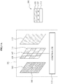
- FIGS. 1A and 1B illustrate a display apparatus and one or more corresponding image capturing and/or displaying methods, according to one or more embodiments.
- the display apparatus 101 may include a display panel 103, a sensor panel 107, a backlight unit 113, and a controller 115, for example.
- the sensor panel may include one or more sensor units 109 and one or more apertures 111.
- the left illustration of FIG. 1A shows a more expanded representation of the display apparatus 101, while the right illustration shows how layers of the display apparatus can be manufactured.
- the manufacturing of the right illustration of FIG. 1A , of the display panel 103, sensor panel 107, and backlight unit 113 may be performed by any conventional semiconductor or optical/display fabrication methodology.
- the below differing arrangements of the display panel 103, sensor panel 107, sensor units 109, apertures 111, backlight units 113, and any potential diffusing layers therein may equally be manufactured in the inventive arrangements by such semiconductor or optical/display panel fabrication methodologies.
- the sensor panel may be constructed of a substrate that can be etched or photo-resist washed to form the apertures 111, so there may be fixed areas where light may be transmitted through, e.g., from the lower backlight unit 113 toward to display panel 103, and fixed areas where light would be blocked.
- this incorporation could also be performed at the time the sensor panel 107 is manufactured, such that when light passed through the one or more apertures the light would be diffused by the diffuser.
- the display panel 103 may be a liquid crystal display (LCD) panel, though embodiments are not limited to the same.
- the display panel 103 may be any panel that may selectively provide one or more pinholes and/or masks enabling the passing of incident light.
- the display panel 103 may operate in a capturing mode or in a displaying mode based on a predetermined criterion of the controller 115. For example, when the display panel 103 refreshes at a frequency of 120 Hz, the display panel 103 may switch between the capturing mode and the displaying mode every refresh over the total 120Hz, e.g., totaling 60 Hz in the capturing mode and 60Hz in the displaying mode.
- the refresh rate of the display panel 103 is the number of times per second in which the display panel 103 can display the data it is given.
- the refresh rate may be the number of times the LCD panel can change states per second, e.g., changing a pixel or sub-pixel from an opaque state to a transparent state, or any available gradation there between, which may be representative of combined times it takes all underlying control operations to be performed.
- the pinholes and/or masks may be selectively provided by the display panel 103 without all or some of the pinholes or masks in one cycle, e.g., while radiating light out of the display 103, and the pinholes and/or masks may be selectively provided by the display panel with all or some of the pinholes or masks in another cycle, e.g., selectively passing light through the display panel 103 toward the sensor panel 107. It may not be required that the pinholes or masks are completely removed during the radiating cycle, and it is not necessary that all available, or the same, pinholes or masks be maintained in every capturing cycle. Alternatively, in an embodiment, all pinholes or masks are removed in the displaying mode.
- the display panel 103 may pass an incident first light, e.g., as reflected from an object, to the sensor panel 107.
- the display panel 103 may be controlled to form one or more patterns for passing the incident first light by controlling a first pixel or a first sub-pixel, for example, to be opaque and by controlling a second pixel or a second sub-pixel, also as an example, different from the first pixel, to be transparent.
- the display panel 103 may be controlled to form a pattern 105, including a circular hole pattern, and may pass the incident first light through the pattern 105.
- the pattern 105 may be formed by the second pixel, and though the second pixel has been described as being only a single pixel or sub-pixel, one or more embodiments include plural neighboring second pixels, e.g., which could be used to control the aperture diameter of the pinhole represented by the pattern 105. Likewise, depending on embodiment and differing uses of the ultimately sensed light, the pattern 105 would not be limited to having only a circular form, and may be non-circular. In an embodiment, the size of the pattern 105 may be controlled to have a same size or number of pixels/sub-pixels for different sized display panels and may be selectively modified based on differing resolutions of each display to maintain the same pattern size.
- the display panel 103 may be controlled to form various types of patterns.
- the display panel 103 may be controlled to form the pattern including at least one of a circular hole, a polygonal hole, and a modified uniformly redundant array (MURA) by combining the first pixel and the second pixel.
- the pattern 105 indicates an optical meaning of a pattern that may pass light instead of blocking light.
- the display panel 103 may be controlled to repeatedly configure the formed pattern based on a number of incident first lights to be passed. For example, when two incident first lights are desired to be passed, the display panel 103 may be controlled to provide two patterns. When four incident first lights are desired to be passed, the display panel 103 may be controlled to provide four patterns.
- the display panel 103 may be controlled to form various types of patterns by changing at least one of a number of opaque first pixels, a number of transparent second pixels, a position of each opaque first pixel, and a position of each transparent second pixel.
- the display panel 103 may be controlled to form a plurality of patterns, and may also change a number of patterns or a position of each pattern at predetermined intervals.
- the display panel 103 may be controlled to form the plurality of patterns horizontally or vertically, or in any other organized arrangement.
- some or all of the patterns or corresponding positions may be randomly chose by the controller 115, and/or some of the patterns or corresponding positions may vary between capturing cycles.
- the display panel 103 may be controlled to clearly outwardly display image data using a second light emitted from the backlight unit 113, radiating light outward toward the display panel 103.
- the sensor panel 107 may be disposed after or below the display panel 103 to acquire image data by sensing the incident first light, e.g., reflected from the object, and passed through the display panel 103 toward the sensor panel 107.
- the sensor panel 107 may include one or more sensor units 109 to sense incident light and apertures 111 to pass light radiating from the backlight, for example, radiating toward the display panel 103.
- the sensor panel 107 may be configured such that the sensor units 109 and the apertures 111 form a grid pattern, or may be configured so the sensor units 109 and the apertures 111 form a repeating pattern, noting that alternative patterns are also available.
- the placement of the sensor units 109 may not be evenly distributed over the entire sensor panel 107, and may be of increased density in one or more areas compared to the density of the apertures 111 in the one or more areas.
- portions of the sensor panel 107 may be made up of all or primarily apertures 111 or sensor units 109.
- portions of the sensor panel 107 may be made up of all or primarily apertures 111 or sensor units 109.
- there may be an increased density of the sensor units 109 so a remote recipient would have the feeling that the user is looking directly at the camera, and directly at the recipient.
- Alternative reasons for changing the densities are equally available.
- the sensor units 109 may be represented by at least one sensor, which may sense the incident first light, e.g., reflected from an object, as passed through the display panel 103. As described above, one or more sensor units 109 may be arranged to sense the respective incident first light passed through the pattern 105 formed in the display panel 103. Here, when there exists a plurality of patterns 105, such as plural holes, one or more sensor units 109 may sense the respective incident first lights passed through the plurality of patterns. The number of sensor units 109 that may be needed to sense the incident light from one such pattern may be calculated, or estimated, and the sensor panel 107 configured accordingly. In one or more embodiments, the sensor layer 105 may be reconfigurable and not fixed as more or less sensor units 109 and more or less apertures 111 may be selectively used or available.
- the sensor unit 109 may acquire image data corresponding to R, G, and B by sensing the incident light that has passed through the pattern 105.
- a pattern formed as an R sub-pixel, a pattern formed as a G sub-pixel, and a pattern formed as a B sub-pixel may be sequentially formed in different cycles, for example, or through neighboring sub-pixels of different colors.
- the number of times incident light from the G sub-pixel is captured may be greater than the respective number of times incident light from the R or B sub-pixels, within the example 120 available cycles. Accordingly, the sensor unit(s) 109 may acquire image data corresponding to R, G, and B by sensing the incident light that has passed through the patterns of the display panel 103.
- each sensor unit 109 may be configured to include a particular color filter to acquire image data corresponding to a corresponding color of the color filter.
- one sensor unit 109 may include a first sensor unit and a second sensor unit.
- Each of the first sensor unit and the second sensor unit may include a differently colored unit color filter.
- each of the first sensor unit and the second sensor unit may include a plurality of color filters having different colors.
- the densities and arrangements of the differently colored filters and corresponding sensor units 109 is not required to be equal or even, and their densities and arrangements may vary based upon embodiment.
- the sensor unit 109 When the sensor unit 109 is configured to have an R color filter, the sensor unit 109 may acquire image data corresponding to the color red by sensing the incident light that has passed through the pattern 105. When the sensor unit 109 is configured to have a G color filter, the sensor unit 109 may acquire image data corresponding to the color green by sensing the incident light that has passed through the pattern 105. When the sensor unit 109 is configured to have a B color filter, the sensor unit 109 may acquire image data corresponding to the color blue by sensing the incident light that has passed through the pattern 105. In one or more embodiments, the arrangement of different filtering sensor units 109 on the sensor panel 107 may be according to different Bayer patterns, for example.
- the aperture 111 of the sensor panel 107 may pass the radiating second light emitted from the backlight unit 113 towards the display panel 103.
- the aperture 111 may be represented by an optical member that may selectively pass light, always pass light, or merely represented by an emptiness in the sensor panel 107, instead of blocking the light.
- the optical member may have one or more lens features for directing light from the backlight unit 113.
- the aperture 111 may be similar to the pattern 105 of the display panel 103, and in one or more embodiments may be controllable to be transparent for the displaying mode and blocking of light in the capturing mode.
- the aperture is a fixed optical member that always permits light to be passed.
- the aperture 111 enables the second light emitted from the backlight unit 113 and radiating towards the display panel 103 to be transferred to the display panel 103 without being blocked by the sensor panel 107. Accordingly, the display panel 103 may clearly display the image data through the apertures 111 even when the sensor units 109 block transmission of one or both of the first incident light and the second light. Similar to above, the densities of sensing units 109 compared to the densities of the apertures 111 may be different, and their arrangements are not required to be fixed, equal, or even.
- the sensor panel is configured to include or use a greater number of apertures 111 than the number of sensor units 109 so as to increase display resolution, or configured to include or use a greater number of sensor units 109 than apertures 111, so as to increase captured image resolution.
- the sensor panel 107 may further include, in the aperture 111, a diffuser to prevent the radiating light from the backlight unit 113 from being partially concentrated, or the sensor panel 107 may be configured to include the backlight unit 113, e.g., in the position of the aperture 111, instead of using the aperture 111.
- the display apparatus 101 may further selectively include a diffuser between the display panel 103 and the sensor panel 107. Also, the display apparatus 101 may prevent the incident first light, to be sensed by the sensor unit 109 of the sensor panel 107, from being blocked by such a diffuser posited before or above the sensor panel 107 by arranging the sensor panel 107 to incorporate the diffuser with the aperture 111 of the sensor panel 107, or when one or more of the backlight units 113 are arranged on the sensor panel 107 instead of the aperture 111, the sensor panel 107 may also include a diffusing layer atop or before each backlight unit 113 to diffuse the light radiated by each backlight unit 113.
- the refresh rate of the display panel may be fixed and frame rates for displayed images would decrease proportionally to the capture rate
- the pattern 105 when the pattern 105 is intentionally not changed upon entering the displaying mode, e.g., even if there may be available image data for display in the same area as the pattern 105 of the display panel 103, if select apertures 111 neighboring a sensor unit(s) 109 corresponding to the pattern 105 are controllable to be opaque, or neighboring backlighting units 113 incorporated into the sensor panel 107 are controlled to not emit their respective second lights, during the displaying mode, an image may be captured from the specific sensor unit(s) 109 at the exact time an image is being displayed through all other portions of the display panel 103 depending on the ambient light effect of neighboring second lights that are radiating through other apertures 111 or emitted by other neighboring backlighting units 113.
- the display may operate at its full refresh rate and images may be captured at their full capture rate.
- alternative embodiments may include the display apparatus 101, or the display device 1100 of FIG. 11A , having the respective display panels 103 specifically engineered to reduce the ambient light effect, e.g., for particular areas of the display.
- the display apparatus 101 or display device 1100 of FIG. 11A may have a functional mode, for example, that would permit additional neighboring apertures to be made opaque or additional backlighting units 113 to be controlled to not emit their respective second lights to reduce the ambient light effect, in which case the controller could also change a vertical or horizontal scanning ratio or aspect ratio of the displayed images to compensate for the loss in viewable space of the display panel 103.
- the term 'simultaneous' with regards to displaying an image and capturing an image means that image capturing can be performed nearly at the same time as image displaying, potentially with either mode following the other in a directly subsequent cycle.
- the term 'same time' means that the capturing and displaying occur within the same cycle.
- the sampling rate and display rate e.g., frames per second, may sum up to be greater than the actual refresh rate of the display panel 103.
- the controller 115 may control a capture rate for capturing images using the sensor layer 107 and a display rate for displaying images using the display panel 103, at the same time to be in total greater than the maximum refresh rate of the display panel 103. Further, the controller 115 may selectively perform the capturing mode and displaying mode simultaneously or at the same time.
- the controller 115 may control the display panel 103 to enable the acquiring or capturing of an object image in the capturing mode and the displaying of image data in the displaying mode by switching the mode of the display panel 103 to/from the capturing mode or the displaying mode based on a predetermined criterion.
- the predetermined criterion may merely be whether the previous operation mode was the capturing mode or the displaying mode, and to currently operate in a different mode, e.g., in an alternating manner.
- the percentage of the cycles such as the percentage of cycles in the 120 available cycles (120Hz refresh rate) of an example LCD panel, for each of the capturing mode and the displaying mode may not be uniform.
- more cycles may be designated for the capturing mode, or more cycles may be designated for the displaying mode.
- the number of cycles a same mode operation is maintained may also change during the total 120 available cycles, as the number of cycles may vary between such same mode operations that the other mode operates.
- These variances between operation modes may be controlled by the controller 115, for example, and may be based on different factors, such as the desired image capturing resolution, the desired image capturing frame-rate, or the desired image displaying resolution.
- These desires may be user controlled and stored in a memory of the display device, and/or may be based on external factors, such at the amount of available light for capturing image, the viewing environment where displayed image is being viewed, the data transportation capabilities or settings between the display device and another display device, such as in teleconferencing, where the captured image data would be encoded and transmitted, either wired or wirelessly, to the other display device.
- the remote display device when the other display device, as an example remote display device, is also a display apparatus 101, the remote display device may also be respectively performing capturing mode and displaying mode operations and respectively equally controlling any of the above controls on image capturing and/or displaying.
- the capturing mode and displaying mode configurations and operations of an example local display device may control the local capturing mode and displaying mode configurations and operations based on the capturing mode and displaying mode configuration and operation settings of the remote display device.
- encoded image data may be coupled with information identifying the settings of the local display device.
- the remote or local display devices may also decode this information identifying the settings of the respective local or remote device. The information may further include indications of why the settings were instituted, such as due limitations in processing or display/capturing capability of either device, or transmission channel limitations.
- the controller 115 may adjust a size of one or more of the patterns formed on the display panel 103 based on a distance between the display panel 103 and the sensor panel 107, or a size of the sensor panel 107.
- the controller 115 may be capable of being used in differently sized display devices, with different resolutions, and/or with different distances between the respective display panel 103 and sensor panel 107, e.g., in an embodiment of the display apparatus 101 where the distance can be modified or when the controller is first determining the appropriate size or location for the pattern 105 and determines the internal dimensions of the display apparatus 101.
- One or more embodiments include a system having plural display devices with respective capturing mode capabilities through respective sensor panels 107 and controllers 115, with each of the configurations of the display devices not being required to have the same configuration, such as the available different arrangements of the pattern 105, sensor units 109, aperture 111, backlight 113, and diffusing elements. Still further, in an embodiment when there are more than two such display devices and more than two remotely generated images are displayed on the local display panel 103, densities of the sensor units 109 in the local sensor panel 107 may be greater in the areas corresponding to the displayed images, compared to densities of the sensor units 109 in other portions of the sensor panel 107. With such an arrangement, both remote viewers may be provided with the feeling that the local viewer is looking directly at each of them.
- the controller 115 may control a power of the backlight unit 113 associated with a light emission towards the display panel 103 based on the mode of the display panel 103 and thereby control the light emitted from the backlight unit 113.
- the controller 115 may power off the backlight unit 113 so that the second light may not be emitted from the backlight unit 113 towards the display unit 103, so the second light does not interfere with the sensing of the incident first light.
- the controller 115 may power on the backlight unit 113 so that the second light may be emitted from the backlight unit 113 towards the display unit 103.
- the aperture 111 may be configured to be controllable to change opacity from opaque to transparent to selectively block the second light, so the back light would not have to cycle on and off.
- the controller 115 may control a sensor image restoring unit, included in the controller 115, as only an example, to interpolate image data acquired by sensing the incident first light using one or more sensor units 109 of the display panel 103, and to restore image data lost due to the inclusion of the aperture 111 in the sensor panel 107, compared to a configuration where the aperture 111 was replaced by another sensor unit 109 that would have sensed the incident first light incident on the same position of the sensor panel 107. Accordingly, the controller 115 may acquire the image data that may more clearly express the corresponding object. In an embodiment, different sensor units 109 or groups of sensor units 109 may be capturing image information for different purposes.
- a sensor unit 109 or a group of sensor units 109 may be capturing image data for transmission to a remote viewing device, while alternate sensor units 109 or groups of sensor units 109 may be capturing image data for motion detection or depth detection.
- the depth detection may be used for encoding the captured image data in a 3D graphics data format, for example, of used for controlling a focus or image compensation based on depth.
- the motion detection may be used with both on-surface (touching the surface of the display device) motion detection and/or off-surface (not touching the surface of the display device) motion detection, for detecting gestures of the user, for example, which may be used to control operations of the display device.
- the controller 115 controls the separate detections, the on/off surface motion detection, and the depth detection. Depending on computational complexity, some detection processes may be delegated to alternate processing elements of the display apparatus 101 or display device 1100, such as shown in FIG. 11A .
- one or more embodiments above enable a user to manipulate operations of the display apparatus 101 through a multi-touch interface based at least on the captured image data by the sensor panel 107, either by directly touching the display or through off-surface gestures or other detectable imaging features that can be inferred or set as a control of the display apparatus 101.
- Control of the display apparatus is available by more than the image detected gestures, such as based on detected environments surrounding the display apparatus 101 or features detected in the facial image of the viewer, including for facial recognition for secure use of the display apparatus 101 or secure access of remote information.
- the mood of the viewer may also be detected.
- One or more embodiments include an interface technology that enables a natural interaction even though the user is at a distance from a screen, such as proximate sensing and touching, gesture recognition and long-distance gesture input, e.g., beyond multiple touches available through on-surface input methods, and detection of a camera level.
- Such multi-touch interface detection, off-surface gesture detection, off-surface image feature detection, facial recognition, emotion detection, and proximate and long-distance gesture detection and input interface are implemented in one or more embodiments based on conventional known techniques, though the capturing of the necessary image and depth information, and transmission and reception of any available remote image data and capture configurations, for example, can only be achieved through the arrangements set forth herein.
- FIG. 1B illustrates the operation of the display panel 103 and sensor panel 107 in acquiring image data with respect to an object with a pinhole camera, according to one or more embodiments.
- the pinhole camera represents at least the pattern 105 of FIG. 1A , for example. Discussions below regarding operations of the pinhole camera, such as calculations being performed, may be performed by the controller 115 of FIG. 1A , or alternative processing devices, such as in the display device 1100 of FIG. 11A .
- the pinhole camera corresponds to a camera forming an image on a sensor pane by employing a pinhole instead of using lenses to focus the incident light.
- the pinhole camera may use, as the pinhole, pattern 105 in the display panel 103, and may use the sensor panel 107 as the sensor plane.
- an effect of a plurality of cameras may be provided.
- Two types of blurs may occur based on the size of the pinhole, e.g., pattern 105 of the display panel 103. For example, when an aperture diameter of the pinhole is relatively large, a blur by a geometric effect may occur. When the aperture diameter of the pinhole is relatively small, a blur by a diffraction effect may occur.
- Equation 1 The blur bG by the geometric effect may be expressed by the below Equation 1, for example.
- b G a d o + d i d o
- Equation 1 do denotes a distance between an object and the pinhole, a denotes the aperture diameter, and di denotes a distance between the pinhole and the sensor plane.
- Equation 2 di denotes the distance between the pinhole and the sensor plane.
- a size b of a final blur corresponds to a sum of the two effects and thus, may be expressed by the below Equation 3, for example.
- Equation 4 the distance between the object and a display panel, or the depth of the object, may be calculated based upon the two blurs.
- this is different than previous approaches, such as in the above referenced Hirsch et al. article, where the authors use Equation 3 (as Equation (1) in Hirsch et al.) for a different purpose to achieve a different answer; the authors used information from the two blurs to determine the angular resolution of their system to control the number of orthographic views, rather than for obtaining depth information.
- the pinhole camera may calculate an inverse impulse response based on the distance do between the object and the pinhole.
- the pinhole camera may further restore distance-based image data by performing de-convolution using the inverse impulse response with respect to the blurred image data acquired by the sensor plane, as shown in the below Equation 5, for example.
- Equation 5 I(x, y) denotes the restored image data, I '(x, y) denotes the blurred image data, and H -1 (x, y) denotes the inverse pulse response.
- the pinhole camera may acquire more accurate image data based on determined distance between the object to the pinhole.
- the controller 115 may accordingly determine the distance between the object and the pattern 105 and then restore the image captured by corresponding one or more sensor units 109 based on that determined distance.
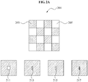
- FIGS. 2A and 2B illustrate a sensor panel 201, such as the sensor panel 107 of FIG. 1A , of a display apparatus, according to one or more embodiments.
- the sensor panel 201 may include a sensor unit 203 to sense incident light and an aperture 205 to pass light radiating from below the sensor panel 201.
- the sensor panel 201 may be configured such that the sensor unit 203 and the aperture 205 are arranged in a grid pattern, or may be configured such that the sensor unit 203 and the aperture 205 are arranged in a repeating pattern. Through this, in an embodiment, the sensor units 203 and the apertures 205 may be uniformly distributed.
- the sensor panel 201 may uniformly acquire an incident first light, e.g., reflected from an object, by having the sensor units 203 and the apertures 205 configured to be distributed, and may uniformly transfer, to an upper display panel, a second light radiating from a backlight unit below the sensor panel 201.
- the sensor panel 201 may acquire image data corresponding to R, G, and B by sensing the light passed through a pattern 211. Also, when the pattern included in the pattern of the display panel is formed based on a sub-pixel unit, a pattern 213 formed as an R sub-pixel, a pattern 215 formed as a G sub-pixel, and a pattern 217 formed as a B sub-pixel may be sequentially formed. Accordingly, the sensor panel 201 may acquire image data corresponding to R, G, and B by respectively sensing the light passing through the patterns 213, 215, and 217.
- Configurations of the sensor pattern 201 are not limited to those shown in FIG. 2A , and thus, configurations of the sensing units to sense the incident light and apertures to pass the radiating light may vary as shown in the different configurations shown in the left, center, and right sensor panel illustrations of FIG. 2B .
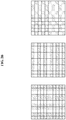
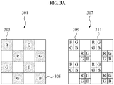
- FIGS. 3A and 3B illustrate sensor panels 301 and 307, such as the sensor panel 107 of FIG. 1A , of a display apparatus, according to one or more embodiments.
- the sensor panel 301 may be configured to include a sensor unit with a color filter to sense incident light that has passed through a pattern of a display panel, such as the pattern 105 of display panel 103 in FIG.1 , and to acquire respective image data corresponding to the color of the color filter.
- the sensor panel 301 may include a first sensor unit and a second sensor unit, for example. Each of the first sensor unit and the second sensor unit may also include respective differently colored unit color filters. Additionally, each of the first sensor unit and the second sensor unit may include a plurality of respective differently colored color filters.
- the first sensor units and the second sensor units may be organized according to any Bayer pattern, for example, and different first sensor units and second sensor units may be filter one or more different colors through different Bayer pattern.
- the sensor panel 301 may be configured to have a first sensor unit 303 as red color unit color filter and to have a second sensor unit 305 as a blue color unit color filter.
- the sensor panel 307 may be configured to have each of the first sensor unit 309 and the second sensor unit 311 include a plurality of RGB color filters.
- the configuration of the sensor panel is not limited to those shown in sensor panels 301 and 307 of FIG. 3A , and thus, the sensor panel may be configured to have various types of color filters as shown the different configurations shown in the upper left, upper right, lower left and lower right sensor panel illustrations in FIG. 3B .
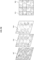
- FIGS. 4A-4B illustrates a sensor panel 401, such as the sensor panel 107, of a display apparatus, according to one or more embodiments.
- the sensor panel 401 may include a sensor unit 403 to sense incident light and a backlight unit 405 to radiate light towards a display panel 407.
- the sensor panel 401 may be configured such that the sensor unit 403 and the backlight unit 405 are configured in a grid pattern, or the sensor unit 403 and the backlight unit 405 may be configured in a repeating pattern, and thus, in one or more embodiments, the sensor units 403 and the backlight units 405 may be uniformly distributed.
- the sensor panel 401 may be configured to uniformly acquire incident first light, e.g., reflected from an object, and to uniformly radiate light.
- the sensor units 403 and the backlight units 405 may be arranged so they are evenly distributed. Accordingly, the sensor panel 401 may uniformly acquire incident light from sensor units 403 and uniformly radiate light from the backlight units 405 to the display panel 407.
- FIG. 4B also illustrates the sensor panel 401 and the display 407, but demonstrates where there are two pinholes or two patterns 105 in the display panel 407, which creates a captured stereo image by respective sensor units 403.
- the sensor panel 401 and the backlight unit 405 may be integrally formed, and thus, it is possible to reduce the internal volume of the display apparatus, by removing the previously required backlight unit disposed below the sensor panel 401, thereby producing light with a slim display apparatus 409. Additionally, with this configuration there is an increase in efficiency of light emission over the arrangement of FIGS. 2A and 2B , for example, as light from a below backlight is not being limited to transmission through only the apertures 111.
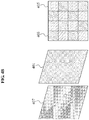
- FIGS. 5A-5B illustrate a sensor panel 501, such as the sensor panel 107 of FIG. 1A , in a display apparatus, according to one or more embodiments.
- the sensor panel 501 may include a sensor unit 503 to sense incident light and a diffuser 505 to diffuse light radiating from a backlight unit 509.
- the sensor panel 501 may be configured to have the sensor unit 503 and the diffuser 505 arranged in a grid pattern, or may be configure to have the sensor unit 503 and the diffuser 505 arranged in a repeating pattern, as only examples. Accordingly, in an embodiment, the sensor units 503 and the diffusers 505 may be uniformly distributed.
- the sensor panel 501 may uniformly acquire incident first light, e.g., reflected from an object, by having the sensor units 503 and the diffusers 505 distributed evenly, and thus, may uniformly radiate a second light emitted from the backlight unit 509 to the display panel 507.
- the display apparatus 511 using the sensor panel 501 including the diffuser 505 may directly sense incident light, passed through the display panel 507, using the sensor panel 501, and thereby acquire accurate image data with respect to an object, for example.
- FIG. 5B also illustrates the sensor panel 501 and the display 507, but demonstrates where there are two pinholes or two patterns 105 in the display panel 507, which creates a captured stereo image by respective sensor units 503.
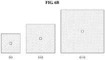
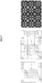
- FIGS. 6A through 6C , and FIG. 7 illustrate plural available patterns that may be formed in a display panel 601, such as the display panel 103 of FIG. 1A , in a display apparatus, according to one or more embodiments.
- the display panel 601 may be controlled to form a pattern 603 by controlling a first pixel to be opaque and by controlling a second pixel, different from the first pixel, to be transparent, and may form a pattern to be included in the pattern 603 so that a light, e.g., reflected from an object, may pass through the pattern 603.
- the display panel 601 may be controlled to form the pattern 603 to include a circular hole pattern. However, as this is only an example, the display panel 601 may be controlled to form a pattern 605, e.g., including a polygonal hole, and a pattern 607 including a MURA image.
- the display panel 601 may be controlled to form a pattern of 11x11 pixels (or sub-pixels), in illustration (i), a pattern of 17x17 pixels (or sub-pixels), in illustration (ii), and/or a pattern of 23x23 pixels (or sub-pixels), in illustration (iii).
- the display panel 601 may equally be controlled to form a MURA pattern of 11x11 pixels (or sub-pixels), in illustration (i), a MURA pattern of 17x17 pixels (or sub-pixels), in illustration (ii), and/or a MURA pattern of 23x23 pixels (or sub-pixels), in illustration (iii).
- the display panel 601 may be controlled to form both a pattern and a MURA pattern, with varying pixel or sub-pixel sizes.
- the illustration (i) of FIG. 6B may also represent a pattern using a single pixel or single sub-pixel.
- the display panel 601 may form a plurality of patterns and may pass incident light, e.g., reflected from an object, using a plurality of patterns.
- the left illustration of FIG. 7 demonstrates the above-referenced stereo image, which may be useful for image capturing of a viewer, while the center and right illustrations of FIG. 7 demonstrate patterns that may be useful for gesture capturing or orthographic capturing of a view or object with greater three-dimensional data, for example.
- the controller 115 of FIG. 1A may resolve the images both for depth and use some or all of the collected image information for generating a single image or one or more less images than patterns.
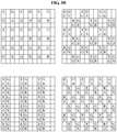
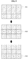
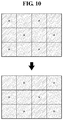
- FIG. 8 through FIG. 10 illustrate patterns that may be formed by a display panel, such as by the display panel 103 of FIG. 1A , included in a display apparatus, according to one or more embodiments.
- the display panel may be controlled to form a plurality of patterns, and may adjust the number of patterns and/or the positions of each pattern by changing at least one of a number of opaque first pixels, a number of transparent second pixels, a position of each opaque first pixel, and a position of each transparent second pixel, for example.
- the display panel may horizontally sequence the plurality of patterns by sequentially forming the plurality of patterns in a first column 801, a second column 803, a third column 805, and a fourth column 807, at predetermined intervals, e.g., in different cycles of the available 120 cycles of an example 120Hz refresh rate of an LCD screen.
- the display panel may be controlled to vertically sequence the plurality of patterns by sequentially forming the plurality of patterns in a first line 901, in a second line 903, and a third line 905, at predetermined intervals, e.g., in different cycles.
- the display panel may be controlled to alternately form the plurality of patterns, e.g., by sequentially changing pattern positions according to an interleaving scheme.
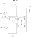
- FIG. 11A through 11C illustrate a display device, system, and method, according to one or more embodiments.
- the display device 1100 includes a display and user interface 1101, a controller 1115, a multimedia decoder 1120, a multimedia encoder 1130, a central processing unit (CPU), a memory 1150, transmitter/receiver 1160, speaker 1170, and microphone 1180, for example.
- the display and user interface 1101 may operate similarly to any of the above described display panels, sensor panels, sensor units, apertures, backlight units, and diffusing arrangements, with the controller 1115 operating as the controller 115 of FIG. 1A , for example.
- the captured image information may be analyzed by the controller 1115 or the necessary processing may be handed off to the CPU, such as where more extensive processing is required in gesture detection, facial detection, image resolution or convolution, and the like.
- the display and user interface 1101 may include user inputs through on/off-screen motion detection or gesture detection, as only example.
- the encoder 1130 may encode the captured image data, including performing any 3D graphics data encoding based upon the determined depth of one or more objects by the controller 1115, for example.
- the encoder may also encode captured audio data with the encoded image data, e.g., captured through the microphone 1180, according to any conventional video/audio encoding schemes, such as any MPEG standard, as only an example.
- the encoder may also encode with or separately the encoded video and audio information and control information, e.g., the above discussed the environment or settings for the capturing and/or displaying modes and corresponding set configurations and arrangements, as only example, used in the image capturing which may be considered by a remote display device, such as in the system of FIG. 11B having first and second display devices.
- the transmitter/receiver 1160 may then transmit the encoded data to the remote display device, such as the second display device of FIG. 11B .
- the transmitter/receiver 1160 may also receive similarly encoded information from the remote display device and forward the same to the decoder 1120, which decodes the video/audio data and any control data from the remote display device.
- the decoded video/audio information is then output through the display and any decoded control information is reviewed by the controller to determine whether to change the current image capturing settings of capturing mode of the display device 1100.
- the system includes the display device and the remote display device of FIG. 11A , as the first display device and second display device in one or more embodiments, each being a display device corresponding to the display device 1100 of FIG. 11A , e.g., including a display and user interface 1101 and encoder and decoder elements.
- the network may be any communication path available between the first display device and the second display device such as an Internet Protocol based network or wireless protocol, or a combination of the same. Both first and second display devices do not need to be a display device corresponding to the display device 1100 of FIG. 11A , and accordingly, it may not be necessary to communicate between display devices how any transmitted image data was generated.
- FIG. 11C an alternative view of the display device 1100 of FIG. 11A is shown, with the viewer using a video call capability of the display device 1100.
- the display devices 1100 of FIGS. 11A and 11B may be any same or different type of display device in the system, including televisions, a personal computer and display as a personal computer system, tablet computer devices, mobile phones, PDAs, teleconferencing devices, set-top boxes, etc.
- the system of FIG. 11B is intended to include any of these devices as either of the first or second display devices without requiring the first or second display devices to be the same type of display device.
- any apparatus, system, and unit descriptions herein include one or more hardware devices and/or hardware processing elements/devices, e.g., controllers incorporated into the displaying system or with hardware elements.
- one or more embodiments include a controlling method and/or a controller device controlling the display panel to generate the pinhole apertures during the capturing mode and controlling the display panel to display an image during the displaying mode, distinctly from a controller that may control the sensor panel, or diffusing aspects.
- Each of these controllers may include such hardware processing elements.
- one or more embodiments may include a configuration similar to that of FIG. 11A , including one or more processing elements in the controller, CPU, display, encoder, and/or decoder hardware portions of the mobile device.
- any described apparatus, system, and unit may further include one or more desirable memories, and any desired hardware input/output transmission devices, as only examples.
- apparatus should be considered synonymous with elements of a physical system, not limited to a device, i.e., a single device at a single location, or enclosure, or limited to all described elements being embodied in single respective element/device or enclosures in all embodiments, but rather, depending on embodiment, is open to being embodied together or separately in differing devices or enclosures and/or differing locations through differing hardware elements.
- embodiments can also be implemented through computer readable code/instructions in/on a non-transitory medium, e.g., a computer readable medium, to control at least one processing element/device, such as a processor, computing device, computer, or computer system with peripherals, to implement any above described embodiment or aspect of any embodiment.
- a non-transitory medium e.g., a computer readable medium
- the medium can correspond to any defined, measurable, and tangible structure permitting the storing and/or transmission of the computer readable code.
- one or more embodiments include the at least one processing element or device.
- the media may also include, e.g., in combination with the computer readable code, data files, data structures, and the like.
- One or more embodiments of computer-readable media include magnetic media such as hard disks, floppy disks, and magnetic tape; optical media such as CD ROM disks and DVDs; magneto-optical media such as optical disks; and hardware devices that are specially configured to store and/or perform program instructions, such as read-only memory (ROM), random access memory (RAM), flash memory, and the at least one processing device, respectively.
- Computer readable code may include both machine code, such as produced by a compiler, and files containing higher level code that may be executed by the computer using an interpreter, for example.
- the media may also be any defined, measurable, and tangible elements of one or more distributed networks, so that the computer readable code is stored and/or executed in a distributed fashion.
- distributed networks do not require the computer readable code to be stored at a same location, e.g., the computer readable code or portions of the same may be stored remotely, either stored remotely at a single location, potentially on a single medium, or stored in a distributed manner, such as in a cloud based manner.
- the processing element could include a processor or a computer processor, and processing elements may be distributed and/or included in a single device. There may be more than one processing element and/or processing elements with plural distinct processing elements, e.g., a processor with plural cores, in which case one or more embodiments would include hardware and/or coding to enable single or plural core synchronous or asynchronous operation.
- the computer-readable media may also be embodied in at least one application specific integrated circuit (ASIC) or Field Programmable Gate Array (FPGA), as only examples, which execute (processes like a processor) program instructions.
- ASIC application specific integrated circuit
- FPGA Field Programmable Gate Array
Landscapes
- Engineering & Computer Science (AREA)
- Physics & Mathematics (AREA)
- General Physics & Mathematics (AREA)
- Multimedia (AREA)
- Signal Processing (AREA)
- Theoretical Computer Science (AREA)
- Computer Hardware Design (AREA)
- Crystallography & Structural Chemistry (AREA)
- Chemical & Material Sciences (AREA)
- Nonlinear Science (AREA)
- Mathematical Physics (AREA)
- Optics & Photonics (AREA)
- Control Of Indicators Other Than Cathode Ray Tubes (AREA)
- Devices For Indicating Variable Information By Combining Individual Elements (AREA)
- Liquid Crystal Display Device Control (AREA)
- Geophysics And Detection Of Objects (AREA)
- Position Input By Displaying (AREA)
- User Interface Of Digital Computer (AREA)
Claims (11)
- Anzeigevorrichtung, die Folgendes umfasst:- ein Sensorfeld (107), das dazu konfiguriert ist, ein erstes einfallendes Licht zu erfassen, das nach dem Durchgehen durch eine Anzeige (103) auf das Sensorfeld einfällt, und die Übertragung von Licht durch das Sensorfeld zumindest teilweise zu blockieren; und- eine Steuerung (115), die dazu konfiguriert ist, die Anzeige wahlweise zu steuern, um das erste einfallende Licht in Richtung des Sensorfelds zu leiten, und dazu konfiguriert ist, die Anzeige so zu steuern, dass Licht von einer Hintergrundbeleuchtungseinheit (113) aus der Anzeige heraus geleitet wird, um ein Bild anzuzeigen;wobei das Sensorfeld erste mehrere unterschiedliche Abschnitte (111) umfasst, die jeweils dazu konfiguriert sind, Licht von dem Sensorfeld in Richtung der Anzeige weiterzuleiten, und zweite mehrere unterschiedliche Abschnitte (109) umfasst, die jeweils dazu konfiguriert sind, die Intensität des einfallenden Lichts zu erfassen, wobei die zweiten mehreren unterschiedlichen Abschnitte sich von den ersten mehreren unterschiedlichen Abschnitten unterscheiden und die Übertragung von Licht durch das Sensorfeld in Richtung der Anzeige blockieren,
wobei die Steuerung dazu konfiguriert ist, die Lichtundurchlässigkeit von Pixeln und/oder Subpixeln der Anzeige wahlweise zu steuern, um Bildmuster auf der Anzeige zum Anzeigen des Bildes auf der Anzeige in einem zweiten Modus zu erzeugen, und mindestens ein Muster (105) auf der Anzeige zu bilden, das so gesteuert wird, dass es transparent ist, und einen das mindestens eine Muster umgebenden Bereich der Anzeige zu bilden, der so gesteuert wird, dass er undurchsichtig ist, um ein Bild durch wenigstens eine Sensoreinheit (109) der zweiten mehreren unterschiedlichen Abschnitte in einem ersten Modus aufzunehmen, und eine Tiefe eines Objekts zu bestimmen, das in dem ersten einfallenden Licht dargestellt wird;
DADURCH GEKENNZEICHNET, DASS
die Steuerung (115) weiterhin dazu konfiguriert ist, die Tiefe eines Objekts zu bestimmen, das in dem ersten einfallenden Licht dargestellt wird, und zwar basierend auf wenigstens einer erfassten Größe einer Unschärfe wenigstens eines von dem Sensorfeld (107) erfassten Musters, und dazu, ein aufgenommenes Bild wiederherzustellen, indem eine entfernungsbasierte Impulsantwort basierend auf der bestimmten Tiefe berechnet wird, indem eine Verschiebung des aufgenommenen Bildes unter Verwendung der entfernungsbasierten Impulsantwort durchgeführt wird, um Brechungs- oder geometrische Effekte zu kompensieren, die durch das wenigstens eine Muster der Anzeige verursacht werden. - Anzeigevorrichtung nach Anspruch 1, wobei die Steuerung dazu konfiguriert ist, wahlweise die Anzeige so zu steuern, dass das Durchgehen des ersten einfallenden Lichts in Richtung des Sensorfelds nur in einem ersten Zyklus von mehreren Zyklen mit fester Zeitlänge ermöglicht wird, und die Anzeige so zu steuern, dass das Durchgehen des Lichts aus der Anzeige ermöglicht wird, damit das Bild nur in einem zweiten Zyklus der mehreren Zyklen mit fester Zeitlänge angezeigt wird, wobei es sich bei der festen Zeit um eine Zeit handelt, die die Anzeige benötigt, um eine Aktualisierung durchzuführen.
- Anzeigevorrichtung nach Anspruch 1 oder 2, wobei, wenn die Steuerung dazu konfiguriert ist, wahlweise mehrere Bilder, die aus mehreren Erfassungen von jeweiligen ersten einfallenden Lichtern, die eine Aufnahmerate darstellen, von einem Muster der von der Steuerung gesteuerten Anzeige aufgenommen werden sollen, derart zu steuern, dass sie sich nicht ändern, wenn die Steuerung die Anzeige dazu steuert, das Bild anzuzeigen, die Steuerung dazu konfiguriert ist, die Aufnahmerate plus eine Anzeigerate zum Anzeigen mehrerer Bilder so zu steuern, dass sie größer als eine maximale Aktualisierungsrate der Anzeige ist.
- Anzeigevorrichtung nach Anspruch 1, 2 oder 3, wobei die Steuerung dazu konfiguriert ist, mehrere Tiefenmessungen des Objekts zu bestimmen, das in mehreren ersten einfallenden Lichtern dargestellt wird, die jeweils von dem Sensorfeld erfasst werden, und zwar jeweils basierend auf wenigstens einer erfassten Größe eines Unschärfemusters für jedes erfasste einfallende Licht, und dazu, 3D-Informationen des Objekts zu erzeugen, wobei die Steuerung dazu konfiguriert ist, eine Überwachung der Bewegung durch das Objekt über mehrere aufgenommene Bilder, und jeweils erzeugter mehrerer 3D-Informationen zu steuern, und zu bestimmen, ob die überwachte Bewegung und die überwachten erzeugten mehreren 3D-Informationen angeben, dass eine Geste von mehreren definierten Gesten durch die Bewegung des Objekts gemacht wird.
- Anzeigevorrichtung nach einem der vorhergehenden Ansprüche, die weiterhin Folgendes umfasst:- ein Anzeigefeld als die Anzeige.
- Anzeigevorrichtung nach einem der vorhergehenden Ansprüche, die Folgendes umfasst:mehr als eine Hintergrundbeleuchtungseinheit, die jeweils an den ersten mehreren unterschiedlichen Abschnitten des Sensorfeldes ausgerichtet sind, um jeweils ein zweites Licht in Richtung der Anzeige zu emittieren,wobei die Steuerung dazu konfiguriert ist, die Anzeige wahlweise zu steuern, um jedes der zweiten Lichter in einem zweiten Modus durch die Anzeige zu leiten.
- Anzeigevorrichtung nach einem der vorhergehenden Ansprüche, wobei die Steuerung dazu konfiguriert ist, die Hintergrundbeleuchtungseinheit so zu steuern, dass sie im zweiten Modus Licht emittiert und während des ersten Modus kein Licht emittiert.
- Anzeigevorrichtung nach einem der vorhergehenden Ansprüche, wobei die Anzeigevorrichtung eines der folgenden ist: ein Fernseher, ein Personalcomputersystem, eine Tablet-Computervorrichtung, ein Mobiltelefon, ein PDA, Telekonferenzgeräte oder -system oder eine Set-Top-Box mit jeweils mindestens einem Prozessor und Speicher, einem Codierer, der dazu konfiguriert ist, ein Bild zu codieren, das durch die Erfassung durch die Sensortafel im ersten Modus aufgenommen wurde, einem Decodierer, der dazu konfiguriert ist, wenigstens Bilddaten zu decodieren, die aus einer externen Quelle empfangen wurden, und wobei die Steuerung dazu konfiguriert ist, decodierte Bilddaten von dem Decoder an das Anzeigefeld weiterzuleiten und das Anzeigefeld dazu zu steuern, die decodierten Bilddaten im zweiten Modus anzuzeigen, wobei die Steuerung dazu konfiguriert ist, die Lichtundurchlässigkeit von Pixeln und/oder Subpixeln der Anzeige wahlweise zu steuern, um Muster auf der Anzeige zum Anzeigen des Bildes auf der Anzeige in einem zweiten Modus zu erzeugen, und wenigstens ein Muster auf der Anzeigetafel zu bilden, das so gesteuert wird, dass es wenigstens ein transparentes Pixel oder Subpixel beinhaltet, und einen das wenigstens eine Muster umgebenden Bereich der Anzeige zu bilden, der so gesteuert wird, dass er undurchsichtig ist, um ein Bild durch wenigstens eine Sensoreinheit des Sensorfeldes in einem ersten Modus aufzunehmen, wobei das Anzeigefeld im ersten Modus und im zweiten Modus unterschiedlich von der Steuerung gesteuert wird.
- Anzeigevorrichtung nach einem der Ansprüche 1 bis 7, wobei die Anzeigevorrichtung eines der folgenden ist: ein Fernseher, ein Personalcomputersystem, eine Tablet-Computervorrichtung, ein Mobiltelefon, ein PDA, Telekonferenzgeräte oder -system oder eine Set-Top-Box mit jeweils mindestens einem Prozessor und Speicher, einem Codierer, der dazu konfiguriert ist, ein Bild zu codieren, das durch die Erfassung durch die Sensortafel im ersten Modus aufgenommen wurde, einem Decodierer, der dazu konfiguriert ist, wenigstens Bilddaten zu decodieren, die aus einer externen Quelle empfangen wurden, und wobei die Steuerung dazu konfiguriert, decodierte Bilddaten von dem Decoder an das Anzeigefeld weiterzuleiten und das Anzeigefeld dazu zu steuern, die decodierten Bilddaten im zweiten Modus anzuzeigen, wobei die Steuerung dazu konfiguriert ist, eine Überwachung der Bewegung eines Objekts, das in dem ersten einfallenden Licht dargestellt wird, über mehrere aufgenommene Bilder, und jeweils erzeugter mehrerer 3D-Informationen für das Objekt zu steuern, und zu bestimmen, ob die überwachte Bewegung und die überwachten erzeugten mehreren 3D-Informationen angeben, dass eine Geste von mehreren definierten Gesten durch die Bewegung des Objekts gemacht wird.
- Anzeigevorrichtung nach einem der vorhergehenden Ansprüche, wobei die Hintergrundbeleuchtungseinheit dazu konfiguriert ist, das Licht zu erzeugen, das von den ersten mehreren unterschiedlichen Abschnitten des Sensorfeldes weitergeleitet werden soll, wobei das Sensorfeld Folgendes umfasst: mehrere Sensoreinheiten zum Erfassen des ersten einfallenden Lichts in einem ersten Modus; und mehrere Öffnungen jeweils als die zweiten mehreren unterschiedlichen Abschnitte, um das zweite von der Hintergrundbeleuchtungseinheit emittierte Licht im ersten und im zweiten Modus in Richtung der Anzeige zu leiten, wobei die Steuerung dazu konfiguriert ist, die Anzeige derart zu steuern, dass sie im zweiten Modus ein Bild anzeigt; wobei die mehreren Sensoreinheiten und mehreren Öffnungen in einem Gittermuster über dem Sensorfeld angeordnet sind, wobei die Öffnungen jeweils einen Diffusor enthalten, um das zweite Licht zu streuen.
- Anzeigeverfahren zum Betrieb der Anzeigevorrichtung nach einem der vorhergehenden Ansprüche, wobei das Verfahren Folgendes umfasst:- wahlweises Konfigurieren einer Anzeige, um ein Muster mit wenigstens einem transparenten Pixel oder Subpixel zu bilden, um ein erstes einfallendes Licht durch die Anzeige und in Richtung eines Sensorfeldes hinter der Anzeige zu leiten, und um einen undurchsichtigen Bereich zu bilden, der wenigstens das Muster umgibt, wenn es sich bei einem aktuellen Modus um einen ersten Modus handelt, und Konfigurieren der Anzeige, um Licht von einer Hintergrundbeleuchtung hinter dem Sensorfeld durch die Anzeige zu leiten, wenn es sich bei einem aktuellen Modus um einen zweiten Modus handelt;- Erfassen des ersten einfallenden Lichts, das durch die Anzeige hindurchgegangen ist, beim Einfallen auf das Sensorfeld, das die Übertragung von Licht von der Hintergrundbeleuchtungseinheit an mehreren unterschiedlichen Abschnitten zumindest teilweise blockiert, wobei die zweiten mehreren unterschiedlichen Abschnitte sich von den ersten mehreren unterschiedlichen Abschnitten unterscheiden in einem ersten Modus;- Anzeigen eines Bildes auf der Anzeige mittels Durchleiten von Licht von der Hintergrundbeleuchtungseinheit an erste mehrere unterschiedliche Abschnitte in einer Richtung von der Sensorschicht durch die Anzeige; und- wiederholtes Steuern des aktuellen Modus auf nur einen aus dem ersten und dem zweiten Modus, einschließlich wenigstens einer mehrmaligen Änderung des aktuellen Modus,GEKENNZEICHNET DURCH
Bestimmen der Tiefe eines Objekts, das in dem ersten einfallenden Licht dargestellt wird, und zwar basierend auf wenigstens einer erfassten Größe einer Unschärfe wenigstens eines von dem Sensorfeld (107) erfassten Musters, und
Wiederherstellen eines aufgenommenen Bildes, indem eine entfernungsbasierte Impulsantwort basierend auf der bestimmten Tiefe berechnet wird, indem eine Verschiebung des aufgenommenen Bildes unter Verwendung der entfernungsbasierten Impulsantwort durchgeführt wird, um Brechungs- oder geometrische Effekte zu kompensieren, die durch das wenigstens eine Muster der Anzeige verursacht werden.
Applications Claiming Priority (1)
| Application Number | Priority Date | Filing Date | Title |
|---|---|---|---|
| KR1020100049564A KR101725044B1 (ko) | 2010-05-27 | 2010-05-27 | 촬영이 가능한 디스플레이 장치 |
Publications (3)
| Publication Number | Publication Date |
|---|---|
| EP2390872A2 EP2390872A2 (de) | 2011-11-30 |
| EP2390872A3 EP2390872A3 (de) | 2015-11-25 |
| EP2390872B1 true EP2390872B1 (de) | 2020-12-23 |
Family
ID=44582076
Family Applications (1)
| Application Number | Title | Priority Date | Filing Date |
|---|---|---|---|
| EP11167488.3A Active EP2390872B1 (de) | 2010-05-27 | 2011-05-25 | Bilderfassungs- und -anzeigevorrichtung und -verfahren |
Country Status (6)
| Country | Link |
|---|---|
| US (2) | US9549134B2 (de) |
| EP (1) | EP2390872B1 (de) |
| JP (1) | JP6448190B2 (de) |
| KR (1) | KR101725044B1 (de) |
| CN (1) | CN102918579B (de) |
| WO (1) | WO2011149303A2 (de) |
Families Citing this family (29)
| Publication number | Priority date | Publication date | Assignee | Title |
|---|---|---|---|---|
| US9030466B2 (en) * | 2010-10-05 | 2015-05-12 | Empire Technology Development Llc | Generation of depth data based on spatial light pattern |
| US20130002722A1 (en) * | 2011-07-01 | 2013-01-03 | Krimon Yuri I | Adaptive text font and image adjustments in smart handheld devices for improved usability |
| US9628843B2 (en) * | 2011-11-21 | 2017-04-18 | Microsoft Technology Licensing, Llc | Methods for controlling electronic devices using gestures |
| JP6004495B2 (ja) * | 2012-01-04 | 2016-10-12 | Necディスプレイソリューションズ株式会社 | ディスプレイ装置とその輝度検出方法 |
| KR102059359B1 (ko) * | 2012-11-13 | 2019-12-26 | 삼성전자주식회사 | 디스플레이 장치, 디스플레이 장치의 동작 방법 및 제조 방법 |
| KR101905528B1 (ko) * | 2012-12-28 | 2018-10-08 | 삼성전자주식회사 | 깊이 정보를 획득하는 방법 및 디스플레이 장치 |
| US10257506B2 (en) * | 2012-12-28 | 2019-04-09 | Samsung Electronics Co., Ltd. | Method of obtaining depth information and display apparatus |
| US9240162B2 (en) * | 2012-12-31 | 2016-01-19 | Lg Display Co., Ltd. | Transparent display apparatus and method for controlling the same |
| US9286710B2 (en) * | 2013-05-14 | 2016-03-15 | Google Inc. | Generating photo animations |
| KR102461652B1 (ko) * | 2015-11-30 | 2022-11-02 | 삼성전자주식회사 | 전자 기기 및 그 제어 방법 |
| CN106067941B (zh) * | 2016-04-18 | 2020-03-17 | 宿州安科迪智能技术有限公司 | 利用相机瓷砖化实现实时多尺度成像系统及方法 |
| CN105847635A (zh) * | 2016-06-20 | 2016-08-10 | 联想(北京)有限公司 | 成像实现方法、摄像装置及电子设备 |
| US20180077437A1 (en) | 2016-09-09 | 2018-03-15 | Barrie Hansen | Parallel Video Streaming |
| WO2018162985A1 (en) * | 2017-03-10 | 2018-09-13 | Zyetric Augmented Reality Limited | Interactive augmented reality |
| CN108664177B (zh) * | 2017-03-29 | 2021-11-12 | 上海耕岩智能科技有限公司 | 一种基于指纹识别开启应用的方法和装置 |
| CN115798365A (zh) * | 2018-04-08 | 2023-03-14 | 北京小米移动软件有限公司 | 显示面板、光电检测方法、装置及计算机可读存储介质 |
| US10733413B2 (en) * | 2018-08-29 | 2020-08-04 | Fingerprint Cards Ab | Optical in-display fingerprint sensor and method for manufacturing such a sensor |
| EP3871144A4 (de) * | 2018-10-26 | 2021-12-15 | Fingerprint Cards Anacatum IP AB | Biometrische bildaufnahmeanordnung unter einem display |
| US10297697B1 (en) * | 2018-11-01 | 2019-05-21 | H3D, Inc. | Coded aperture system of imaging with a plurality of detectors in a spaced-apart configuration |
| KR102617951B1 (ko) * | 2018-11-15 | 2023-12-26 | 삼성전자주식회사 | 디스플레이장치 및 그 제어방법 |
| US11514027B2 (en) * | 2019-06-07 | 2022-11-29 | Sap Se | Paged hybrid LOBs |
| CN110930953A (zh) * | 2019-11-22 | 2020-03-27 | 深圳市华星光电半导体显示技术有限公司 | mini-LED背光模组及液晶显示面板 |
| CN113497887A (zh) * | 2020-04-03 | 2021-10-12 | 中兴通讯股份有限公司 | 拍摄方法、电子设备及存储介质 |
| US11595575B2 (en) * | 2020-05-11 | 2023-02-28 | Samsung Electronics Co., Ltd. | Image sensor |
| CN114125207A (zh) * | 2020-08-31 | 2022-03-01 | 三星电子株式会社 | 图像传感器、图像获取设备和操作图像获取设备的方法 |
| KR102899907B1 (ko) | 2020-08-31 | 2025-12-18 | 삼성전자주식회사 | 이미지 센서, 이미지 센서를 포함하는 이미지 획득 장치 및 그것의 동작 방법 |
| GB202019760D0 (en) * | 2020-12-15 | 2021-01-27 | Ams Sensors Singapore Pte Ltd | Video user interface and method for use in determining depth information relating to a scene |
| CN117280705A (zh) * | 2021-04-16 | 2023-12-22 | 三星电子株式会社 | 电子装置及其图像捕获方法 |
| CN113689403B (zh) * | 2021-08-24 | 2023-09-19 | 中国科学院长春光学精密机械与物理研究所 | 基于特征间方位距的特征描述系统 |
Family Cites Families (33)
| Publication number | Priority date | Publication date | Assignee | Title |
|---|---|---|---|---|
| US4876590A (en) * | 1988-06-17 | 1989-10-24 | Eastman Kodak Company | Low resolution verifier for a still video image |
| US6404918B1 (en) * | 1999-04-30 | 2002-06-11 | Hewlett-Packard Company | Image demosaicing method utilizing directional smoothing |
| US6989862B2 (en) * | 2001-08-23 | 2006-01-24 | Agilent Technologies, Inc. | System and method for concurrently demosaicing and resizing raw data images |
| US7336430B2 (en) | 2004-09-03 | 2008-02-26 | Micron Technology, Inc. | Extended depth of field using a multi-focal length lens with a controlled range of spherical aberration and a centrally obscured aperture |
| WO2006047487A2 (en) * | 2004-10-25 | 2006-05-04 | The Trustees Of Columbia University In The City Of New York | Systems and methods for displaying three-dimensional images |
| US7767949B2 (en) | 2005-01-18 | 2010-08-03 | Rearden, Llc | Apparatus and method for capturing still images and video using coded aperture techniques |
| US7830561B2 (en) * | 2005-03-16 | 2010-11-09 | The Trustees Of Columbia University In The City Of New York | Lensless imaging with controllable apertures |
| KR100790874B1 (ko) * | 2006-04-28 | 2008-01-03 | 삼성전자주식회사 | 화상표시장치 |
| JP4926762B2 (ja) * | 2006-08-03 | 2012-05-09 | シチズン電子株式会社 | 発光シートモジュール |
| JP4747053B2 (ja) | 2006-08-15 | 2011-08-10 | Nec液晶テクノロジー株式会社 | 液晶表示素子及びこれを搭載した電子機器 |
| US7697053B2 (en) | 2006-11-02 | 2010-04-13 | Eastman Kodak Company | Integrated display having multiple capture devices |
| US8213710B2 (en) * | 2006-11-28 | 2012-07-03 | Youliza, Gehts B.V. Limited Liability Company | Apparatus and method for shift invariant differential (SID) image data interpolation in non-fully populated shift invariant matrix |
| US8040558B2 (en) * | 2006-11-29 | 2011-10-18 | Youliza, Gehts B.V. Limited Liability Company | Apparatus and method for shift invariant differential (SID) image data interpolation in fully populated shift invariant matrix |
| US7808540B2 (en) * | 2007-01-09 | 2010-10-05 | Eastman Kodak Company | Image capture and integrated display apparatus |
| JP4925929B2 (ja) | 2007-06-07 | 2012-05-09 | 株式会社 日立ディスプレイズ | 表示装置 |
| KR20090015320A (ko) * | 2007-08-08 | 2009-02-12 | 삼성전자주식회사 | 디스플레이 모드 전환 장치 및 방법 |
| JP5248062B2 (ja) * | 2007-08-24 | 2013-07-31 | 株式会社東芝 | 指向性バックライト、表示装置及び立体画像表示装置 |
| JP2009086565A (ja) | 2007-10-03 | 2009-04-23 | Mitsubishi Electric Corp | 光センサ内蔵表示装置 |
| JP5068149B2 (ja) | 2007-11-29 | 2012-11-07 | 株式会社ジャパンディスプレイウェスト | 光センサ素子、光センサ素子の駆動方法、表示装置、および表示装置の駆動方法 |
| KR101465220B1 (ko) * | 2007-11-29 | 2014-11-26 | 엘지디스플레이 주식회사 | 이중시역 표시장치 및 이의 화상구현 방법 |
| JP2009146100A (ja) | 2007-12-13 | 2009-07-02 | Sony Corp | 表示装置および光センサ素子 |
| GB0724983D0 (en) * | 2007-12-21 | 2008-01-30 | Cmosis Nv | Pixel array with reduced sensitivity to defects |
| JP5200955B2 (ja) * | 2008-02-14 | 2013-06-05 | 株式会社ニコン | 画像処理装置、撮像装置及び画像処理プログラム |
| WO2009104667A1 (ja) * | 2008-02-21 | 2009-08-27 | シャープ株式会社 | 光センサ付き表示装置 |
| CN101383132B (zh) * | 2008-08-28 | 2010-12-29 | 青岛海信电器股份有限公司 | 液晶显示方法 |
| KR101530995B1 (ko) * | 2008-09-24 | 2015-06-25 | 삼성디스플레이 주식회사 | 표시 장치 및 광학 시트의 제조 방법 |
| US8035698B2 (en) * | 2009-01-21 | 2011-10-11 | Seiko Epson Corporation | Joint automatic demosaicking and white balancing |
| JP5108802B2 (ja) * | 2009-02-03 | 2012-12-26 | 富士フイルム株式会社 | 撮像装置及びそのスルー画像表示方法 |
| US8654234B2 (en) * | 2009-07-26 | 2014-02-18 | Massachusetts Institute Of Technology | Bi-directional screen |
| WO2012124184A1 (ja) * | 2011-03-11 | 2012-09-20 | 富士フイルム株式会社 | 撮像装置およびその動作制御方法ならびに撮像システム |
| JP5433109B2 (ja) * | 2011-03-31 | 2014-03-05 | 富士フイルム株式会社 | 立体撮像装置および立体撮像方法 |
| US20150332433A1 (en) * | 2012-12-14 | 2015-11-19 | Konica Minolta, Inc. | Imaging device |
| WO2015199163A1 (ja) * | 2014-06-24 | 2015-12-30 | 日立マクセル株式会社 | 撮像センサおよび撮像装置 |
-
2010
- 2010-05-27 KR KR1020100049564A patent/KR101725044B1/ko active Active
-
2011
- 2011-05-25 US US13/067,337 patent/US9549134B2/en active Active
- 2011-05-25 EP EP11167488.3A patent/EP2390872B1/de active Active
- 2011-05-27 JP JP2013512547A patent/JP6448190B2/ja active Active
- 2011-05-27 WO PCT/KR2011/003900 patent/WO2011149303A2/en not_active Ceased
- 2011-05-27 CN CN201180008918.5A patent/CN102918579B/zh active Active
-
2017
- 2017-01-12 US US15/404,768 patent/US10477111B2/en active Active
Non-Patent Citations (1)
| Title |
|---|
| None * |
Also Published As
| Publication number | Publication date |
|---|---|
| JP6448190B2 (ja) | 2019-01-09 |
| WO2011149303A3 (en) | 2012-03-08 |
| CN102918579A (zh) | 2013-02-06 |
| US9549134B2 (en) | 2017-01-17 |
| KR101725044B1 (ko) | 2017-04-11 |
| WO2011149303A2 (en) | 2011-12-01 |
| KR20110130102A (ko) | 2011-12-05 |
| JP2013535020A (ja) | 2013-09-09 |
| US20170126982A1 (en) | 2017-05-04 |
| US20110304532A1 (en) | 2011-12-15 |
| CN102918579B (zh) | 2016-03-23 |
| EP2390872A2 (de) | 2011-11-30 |
| EP2390872A3 (de) | 2015-11-25 |
| US10477111B2 (en) | 2019-11-12 |
Similar Documents
| Publication | Publication Date | Title |
|---|---|---|
| EP2390872B1 (de) | Bilderfassungs- und -anzeigevorrichtung und -verfahren | |
| US9866825B2 (en) | Multi-view image display apparatus and control method thereof | |
| US9172949B2 (en) | Display apparatus and method | |
| CN101923249B (zh) | 显示装置和方法 | |
| CN104871453B (zh) | 影像显示方法和装置 | |
| KR20130056506A (ko) | 입체영상 처리 장치 및 입체영상 처리 장치의 칼리브레이션 방법 | |
| EP2663081A2 (de) | 3d-anzeigevorrichtung und -verfahren | |
| US11172190B2 (en) | Stereo weaving for head-tracked autostereoscopic displays | |
| US10419746B2 (en) | 3D display apparatus and 3D display method | |
| KR20120034581A (ko) | 배리어를 이용하는 3d 디스플레이 장치 및 그 구동 방법 | |
| CN103327349B (zh) | 三维图像处理装置和调整显示图像的最佳点的位置的方法 | |
| US20130093762A1 (en) | Display device and method for controlling the same | |
| US9064444B2 (en) | Three-dimensional display device | |
| US10939092B2 (en) | Multiview image display apparatus and multiview image display method thereof | |
| TW201430388A (zh) | 多視點三維顯示器系統及其控制方法 | |
| JP2013027041A (ja) | 映像処理方法及び立体映像表示装置 | |
| EP2713615A2 (de) | Anzeige für mehrere Betrachter und Anzeigeverfahren dafür | |
| EP4456530B1 (de) | Anzeigevorrichtung zur bereitstellung eines 3d-bildes und verfahren zur steuerung davon | |
| JP5932807B2 (ja) | 3dディスプレイパネルおよびそれを用いる3dディスプレイ装置とその駆動方法 | |
| US20250080713A1 (en) | Augmented superstereoscopic display | |
| JP5573426B2 (ja) | 音声処理装置、音声処理方法、およびプログラム | |
| KR20240005492A (ko) | 3d 영상을 제공하는 디스플레이 장치 및 그 제어 방법 | |
| Shen et al. | 3-D perception enhancement in autostereoscopic TV by depth cue for 3-D model interaction | |
| KR20130038658A (ko) | 이동 단말기 |
Legal Events
| Date | Code | Title | Description |
|---|---|---|---|
| AK | Designated contracting states |
Kind code of ref document: A2 Designated state(s): AL AT BE BG CH CY CZ DE DK EE ES FI FR GB GR HR HU IE IS IT LI LT LU LV MC MK MT NL NO PL PT RO RS SE SI SK SM TR |
|
| AX | Request for extension of the european patent |
Extension state: BA ME |
|
| PUAI | Public reference made under article 153(3) epc to a published international application that has entered the european phase |
Free format text: ORIGINAL CODE: 0009012 |
|
| RAP1 | Party data changed (applicant data changed or rights of an application transferred) |
Owner name: SAMSUNG ELECTRONICS CO., LTD. |
|
| PUAL | Search report despatched |
Free format text: ORIGINAL CODE: 0009013 |
|
| AK | Designated contracting states |
Kind code of ref document: A3 Designated state(s): AL AT BE BG CH CY CZ DE DK EE ES FI FR GB GR HR HU IE IS IT LI LT LU LV MC MK MT NL NO PL PT RO RS SE SI SK SM TR |
|
| AX | Request for extension of the european patent |
Extension state: BA ME |
|
| RIC1 | Information provided on ipc code assigned before grant |
Ipc: G09G 3/34 20060101AFI20151016BHEP |
|
| 17P | Request for examination filed |
Effective date: 20160331 |
|
| RBV | Designated contracting states (corrected) |
Designated state(s): AL AT BE BG CH CY CZ DE DK EE ES FI FR GB GR HR HU IE IS IT LI LT LU LV MC MK MT NL NO PL PT RO RS SE SI SK SM TR |
|
| STAA | Information on the status of an ep patent application or granted ep patent |
Free format text: STATUS: EXAMINATION IS IN PROGRESS |
|
| 17Q | First examination report despatched |
Effective date: 20190409 |
|
| GRAP | Despatch of communication of intention to grant a patent |
Free format text: ORIGINAL CODE: EPIDOSNIGR1 |
|
| STAA | Information on the status of an ep patent application or granted ep patent |
Free format text: STATUS: GRANT OF PATENT IS INTENDED |
|
| INTG | Intention to grant announced |
Effective date: 20201007 |
|
| GRAS | Grant fee paid |
Free format text: ORIGINAL CODE: EPIDOSNIGR3 |
|
| GRAA | (expected) grant |
Free format text: ORIGINAL CODE: 0009210 |
|
| STAA | Information on the status of an ep patent application or granted ep patent |
Free format text: STATUS: THE PATENT HAS BEEN GRANTED |
|
| AK | Designated contracting states |
Kind code of ref document: B1 Designated state(s): AL AT BE BG CH CY CZ DE DK EE ES FI FR GB GR HR HU IE IS IT LI LT LU LV MC MK MT NL NO PL PT RO RS SE SI SK SM TR |
|
| REG | Reference to a national code |
Ref country code: GB Ref legal event code: FG4D |
|
| REG | Reference to a national code |
Ref country code: DE Ref legal event code: R096 Ref document number: 602011069711 Country of ref document: DE |
|
| REG | Reference to a national code |
Ref country code: AT Ref legal event code: REF Ref document number: 1348487 Country of ref document: AT Kind code of ref document: T Effective date: 20210115 |
|
| REG | Reference to a national code |
Ref country code: IE Ref legal event code: FG4D |
|
| PG25 | Lapsed in a contracting state [announced via postgrant information from national office to epo] |
Ref country code: GR Free format text: LAPSE BECAUSE OF FAILURE TO SUBMIT A TRANSLATION OF THE DESCRIPTION OR TO PAY THE FEE WITHIN THE PRESCRIBED TIME-LIMIT Effective date: 20210324 Ref country code: NO Free format text: LAPSE BECAUSE OF FAILURE TO SUBMIT A TRANSLATION OF THE DESCRIPTION OR TO PAY THE FEE WITHIN THE PRESCRIBED TIME-LIMIT Effective date: 20210323 Ref country code: FI Free format text: LAPSE BECAUSE OF FAILURE TO SUBMIT A TRANSLATION OF THE DESCRIPTION OR TO PAY THE FEE WITHIN THE PRESCRIBED TIME-LIMIT Effective date: 20201223 Ref country code: RS Free format text: LAPSE BECAUSE OF FAILURE TO SUBMIT A TRANSLATION OF THE DESCRIPTION OR TO PAY THE FEE WITHIN THE PRESCRIBED TIME-LIMIT Effective date: 20201223 |
|
| REG | Reference to a national code |
Ref country code: AT Ref legal event code: MK05 Ref document number: 1348487 Country of ref document: AT Kind code of ref document: T Effective date: 20201223 |
|
| REG | Reference to a national code |
Ref country code: NL Ref legal event code: MP Effective date: 20201223 |
|
| PG25 | Lapsed in a contracting state [announced via postgrant information from national office to epo] |
Ref country code: LV Free format text: LAPSE BECAUSE OF FAILURE TO SUBMIT A TRANSLATION OF THE DESCRIPTION OR TO PAY THE FEE WITHIN THE PRESCRIBED TIME-LIMIT Effective date: 20201223 Ref country code: SE Free format text: LAPSE BECAUSE OF FAILURE TO SUBMIT A TRANSLATION OF THE DESCRIPTION OR TO PAY THE FEE WITHIN THE PRESCRIBED TIME-LIMIT Effective date: 20201223 Ref country code: BG Free format text: LAPSE BECAUSE OF FAILURE TO SUBMIT A TRANSLATION OF THE DESCRIPTION OR TO PAY THE FEE WITHIN THE PRESCRIBED TIME-LIMIT Effective date: 20210323 |
|
| PG25 | Lapsed in a contracting state [announced via postgrant information from national office to epo] |
Ref country code: NL Free format text: LAPSE BECAUSE OF FAILURE TO SUBMIT A TRANSLATION OF THE DESCRIPTION OR TO PAY THE FEE WITHIN THE PRESCRIBED TIME-LIMIT Effective date: 20201223 Ref country code: HR Free format text: LAPSE BECAUSE OF FAILURE TO SUBMIT A TRANSLATION OF THE DESCRIPTION OR TO PAY THE FEE WITHIN THE PRESCRIBED TIME-LIMIT Effective date: 20201223 |
|
| REG | Reference to a national code |
Ref country code: LT Ref legal event code: MG9D |
|
| PG25 | Lapsed in a contracting state [announced via postgrant information from national office to epo] |
Ref country code: PT Free format text: LAPSE BECAUSE OF FAILURE TO SUBMIT A TRANSLATION OF THE DESCRIPTION OR TO PAY THE FEE WITHIN THE PRESCRIBED TIME-LIMIT Effective date: 20210423 Ref country code: RO Free format text: LAPSE BECAUSE OF FAILURE TO SUBMIT A TRANSLATION OF THE DESCRIPTION OR TO PAY THE FEE WITHIN THE PRESCRIBED TIME-LIMIT Effective date: 20201223 Ref country code: SK Free format text: LAPSE BECAUSE OF FAILURE TO SUBMIT A TRANSLATION OF THE DESCRIPTION OR TO PAY THE FEE WITHIN THE PRESCRIBED TIME-LIMIT Effective date: 20201223 Ref country code: LT Free format text: LAPSE BECAUSE OF FAILURE TO SUBMIT A TRANSLATION OF THE DESCRIPTION OR TO PAY THE FEE WITHIN THE PRESCRIBED TIME-LIMIT Effective date: 20201223 Ref country code: CZ Free format text: LAPSE BECAUSE OF FAILURE TO SUBMIT A TRANSLATION OF THE DESCRIPTION OR TO PAY THE FEE WITHIN THE PRESCRIBED TIME-LIMIT Effective date: 20201223 Ref country code: EE Free format text: LAPSE BECAUSE OF FAILURE TO SUBMIT A TRANSLATION OF THE DESCRIPTION OR TO PAY THE FEE WITHIN THE PRESCRIBED TIME-LIMIT Effective date: 20201223 Ref country code: SM Free format text: LAPSE BECAUSE OF FAILURE TO SUBMIT A TRANSLATION OF THE DESCRIPTION OR TO PAY THE FEE WITHIN THE PRESCRIBED TIME-LIMIT Effective date: 20201223 |
|
| PG25 | Lapsed in a contracting state [announced via postgrant information from national office to epo] |
Ref country code: AT Free format text: LAPSE BECAUSE OF FAILURE TO SUBMIT A TRANSLATION OF THE DESCRIPTION OR TO PAY THE FEE WITHIN THE PRESCRIBED TIME-LIMIT Effective date: 20201223 Ref country code: PL Free format text: LAPSE BECAUSE OF FAILURE TO SUBMIT A TRANSLATION OF THE DESCRIPTION OR TO PAY THE FEE WITHIN THE PRESCRIBED TIME-LIMIT Effective date: 20201223 |
|
| REG | Reference to a national code |
Ref country code: DE Ref legal event code: R097 Ref document number: 602011069711 Country of ref document: DE |
|
| PG25 | Lapsed in a contracting state [announced via postgrant information from national office to epo] |
Ref country code: IS Free format text: LAPSE BECAUSE OF FAILURE TO SUBMIT A TRANSLATION OF THE DESCRIPTION OR TO PAY THE FEE WITHIN THE PRESCRIBED TIME-LIMIT Effective date: 20210423 |
|
| PG25 | Lapsed in a contracting state [announced via postgrant information from national office to epo] |
Ref country code: AL Free format text: LAPSE BECAUSE OF FAILURE TO SUBMIT A TRANSLATION OF THE DESCRIPTION OR TO PAY THE FEE WITHIN THE PRESCRIBED TIME-LIMIT Effective date: 20201223 Ref country code: IT Free format text: LAPSE BECAUSE OF FAILURE TO SUBMIT A TRANSLATION OF THE DESCRIPTION OR TO PAY THE FEE WITHIN THE PRESCRIBED TIME-LIMIT Effective date: 20201223 |
|
| PLBE | No opposition filed within time limit |
Free format text: ORIGINAL CODE: 0009261 |
|
| STAA | Information on the status of an ep patent application or granted ep patent |
Free format text: STATUS: NO OPPOSITION FILED WITHIN TIME LIMIT |
|
| PG25 | Lapsed in a contracting state [announced via postgrant information from national office to epo] |
Ref country code: ES Free format text: LAPSE BECAUSE OF FAILURE TO SUBMIT A TRANSLATION OF THE DESCRIPTION OR TO PAY THE FEE WITHIN THE PRESCRIBED TIME-LIMIT Effective date: 20201223 Ref country code: DK Free format text: LAPSE BECAUSE OF FAILURE TO SUBMIT A TRANSLATION OF THE DESCRIPTION OR TO PAY THE FEE WITHIN THE PRESCRIBED TIME-LIMIT Effective date: 20201223 |
|
| 26N | No opposition filed |
Effective date: 20210924 |
|
| REG | Reference to a national code |
Ref country code: CH Ref legal event code: PL |
|
| PG25 | Lapsed in a contracting state [announced via postgrant information from national office to epo] |
Ref country code: LI Free format text: LAPSE BECAUSE OF NON-PAYMENT OF DUE FEES Effective date: 20210531 Ref country code: LU Free format text: LAPSE BECAUSE OF NON-PAYMENT OF DUE FEES Effective date: 20210525 Ref country code: MC Free format text: LAPSE BECAUSE OF FAILURE TO SUBMIT A TRANSLATION OF THE DESCRIPTION OR TO PAY THE FEE WITHIN THE PRESCRIBED TIME-LIMIT Effective date: 20201223 Ref country code: CH Free format text: LAPSE BECAUSE OF NON-PAYMENT OF DUE FEES Effective date: 20210531 |
|
| REG | Reference to a national code |
Ref country code: BE Ref legal event code: MM Effective date: 20210531 |
|
| PG25 | Lapsed in a contracting state [announced via postgrant information from national office to epo] |
Ref country code: SI Free format text: LAPSE BECAUSE OF FAILURE TO SUBMIT A TRANSLATION OF THE DESCRIPTION OR TO PAY THE FEE WITHIN THE PRESCRIBED TIME-LIMIT Effective date: 20201223 |
|
| PG25 | Lapsed in a contracting state [announced via postgrant information from national office to epo] |
Ref country code: IE Free format text: LAPSE BECAUSE OF NON-PAYMENT OF DUE FEES Effective date: 20210525 |
|
| PG25 | Lapsed in a contracting state [announced via postgrant information from national office to epo] |
Ref country code: IS Free format text: LAPSE BECAUSE OF FAILURE TO SUBMIT A TRANSLATION OF THE DESCRIPTION OR TO PAY THE FEE WITHIN THE PRESCRIBED TIME-LIMIT Effective date: 20210423 |
|
| PG25 | Lapsed in a contracting state [announced via postgrant information from national office to epo] |
Ref country code: BE Free format text: LAPSE BECAUSE OF NON-PAYMENT OF DUE FEES Effective date: 20210531 |
|
| PG25 | Lapsed in a contracting state [announced via postgrant information from national office to epo] |
Ref country code: HU Free format text: LAPSE BECAUSE OF FAILURE TO SUBMIT A TRANSLATION OF THE DESCRIPTION OR TO PAY THE FEE WITHIN THE PRESCRIBED TIME-LIMIT; INVALID AB INITIO Effective date: 20110525 Ref country code: CY Free format text: LAPSE BECAUSE OF FAILURE TO SUBMIT A TRANSLATION OF THE DESCRIPTION OR TO PAY THE FEE WITHIN THE PRESCRIBED TIME-LIMIT Effective date: 20201223 |
|
| P01 | Opt-out of the competence of the unified patent court (upc) registered |
Effective date: 20230530 |
|
| PG25 | Lapsed in a contracting state [announced via postgrant information from national office to epo] |
Ref country code: MK Free format text: LAPSE BECAUSE OF FAILURE TO SUBMIT A TRANSLATION OF THE DESCRIPTION OR TO PAY THE FEE WITHIN THE PRESCRIBED TIME-LIMIT Effective date: 20201223 |
|
| PG25 | Lapsed in a contracting state [announced via postgrant information from national office to epo] |
Ref country code: MT Free format text: LAPSE BECAUSE OF FAILURE TO SUBMIT A TRANSLATION OF THE DESCRIPTION OR TO PAY THE FEE WITHIN THE PRESCRIBED TIME-LIMIT Effective date: 20201223 |
|
| PGFP | Annual fee paid to national office [announced via postgrant information from national office to epo] |
Ref country code: DE Payment date: 20250408 Year of fee payment: 15 |
|
| PGFP | Annual fee paid to national office [announced via postgrant information from national office to epo] |
Ref country code: GB Payment date: 20250410 Year of fee payment: 15 |
|
| PGFP | Annual fee paid to national office [announced via postgrant information from national office to epo] |
Ref country code: FR Payment date: 20250409 Year of fee payment: 15 |
|
| PG25 | Lapsed in a contracting state [announced via postgrant information from national office to epo] |
Ref country code: TR Free format text: LAPSE BECAUSE OF FAILURE TO SUBMIT A TRANSLATION OF THE DESCRIPTION OR TO PAY THE FEE WITHIN THE PRESCRIBED TIME-LIMIT Effective date: 20201223 |