EP2390705B1 - Zoom-linse, mit zoom-linse ausgestattete optische einrichtung und verfahren zur herstellung einer zoom-linse - Google Patents
Zoom-linse, mit zoom-linse ausgestattete optische einrichtung und verfahren zur herstellung einer zoom-linse Download PDFInfo
- Publication number
- EP2390705B1 EP2390705B1 EP09838854.9A EP09838854A EP2390705B1 EP 2390705 B1 EP2390705 B1 EP 2390705B1 EP 09838854 A EP09838854 A EP 09838854A EP 2390705 B1 EP2390705 B1 EP 2390705B1
- Authority
- EP
- European Patent Office
- Prior art keywords
- lens
- lens group
- object side
- group
- focal length
- Prior art date
- Legal status (The legal status is an assumption and is not a legal conclusion. Google has not performed a legal analysis and makes no representation as to the accuracy of the status listed.)
- Not-in-force
Links
Images


Classifications
-
- G—PHYSICS
- G02—OPTICS
- G02B—OPTICAL ELEMENTS, SYSTEMS OR APPARATUS
- G02B15/00—Optical objectives with means for varying the magnification
- G02B15/14—Optical objectives with means for varying the magnification by axial movement of one or more lenses or groups of lenses relative to the image plane for continuously varying the equivalent focal length of the objective
- G02B15/144—Optical objectives with means for varying the magnification by axial movement of one or more lenses or groups of lenses relative to the image plane for continuously varying the equivalent focal length of the objective having four groups only
- G02B15/1441—Optical objectives with means for varying the magnification by axial movement of one or more lenses or groups of lenses relative to the image plane for continuously varying the equivalent focal length of the objective having four groups only the first group being positive
- G02B15/144113—Optical objectives with means for varying the magnification by axial movement of one or more lenses or groups of lenses relative to the image plane for continuously varying the equivalent focal length of the objective having four groups only the first group being positive arranged +-++
Definitions
- the present invention relates to a zoom lens, an optical apparatus equipped therewith and a method for manufacturing the zoom lens.
- a zoom lens having a four-lens-group configuration of positive-negative-positive-positive has been known (for example, see Japanese Patent Application Laid-Open No. 11-352400 ).
- the positive-negative-positive-positive four-lens-group type zoom lens is composed of four lens groups which are, in order from an object side, a first lens group having positive refractive power, a second lens group having negative refractive power, a third lens group having positive refractive power, and a fourth lens group having positive refractive power.
- a conventional optical system cannot obtain sufficient optical performance over large photographing area, and tends to become large because of a large aperture.
- portability becomes worse.
- a zoom lens having a wide angle of view has been requested. With using a wider angle of view, it becomes possible to enjoy photograph with high flexibility.
- a high zoom ratio, a wider angle of view and high optical performance are very hard to compatible. Even if they are compatible, the optical system becomes large.
- JP 2004 199000 relates to a zoom lens with a first lens group having positive refractive power, a second lens group having negative refractive power, a third lens group having positive refractive power and a fourth lens group having positive refractive power in order from an object side.
- lens groups are moved so that relative distances between respective lens groups change, and a prescribed conditional expression is satisfied.
- US 2008/0019018 A1 relates to a zoom lens with a first lens group having positive refractive power, a second lens group having negative refractive power, a third lens group having positive refractive power and a fourth lens group having positive refractive power four lens groups, and a vibration reduction function by moving the rear group of the third lens group perpendicular to the optical axis.
- US 2001/0022696 A1 relates to a zoom lens with a first lens unit having positive refractive power, a second lens unit having negative refractive power, a third lens unit having positive refractive power and a fourth lens unit having positive refractive power, and a second lens subunit of the third lens unit can be moved perpendicular to the optical axis to displace an image.
- EP 2 056 152 A2 relates to a zoom lens with a first lens group having positive refractive power, a second lens group having negative refractive power, a third lens group having positive refractive power and a fourth lens group having positive refractive power in order from an object side.
- the first and fourth lens groups move to the object side and on focusing, a rear lens group of the fourth lens group is moved along the optical axis.
- the present invention is made in view of the above-described problems, and has an object to provide a downsized zoom lens having excellent optical performance, an optical apparatus equipped therewith and a method for manufacturing the zoom lens.
- a zoom lens as set out in claim 1.
- conditional expression (3) 0.10 ⁇ fw / f 3 ⁇ 0.50 where fw denotes a focal length of the zoom lens in a wide-angle end state, and f3 denotes a focal length of the third lens group.
- the first lens group and the fourth lens group are moved to the object side such that a distance between the first lens group and the second lens group varies, a distance between the second lens group and the third lens group varies, and a distance between the third lens group and the fourth lens group varies.
- a distance between the first lens group and the second lens group increases, a distance between the second lens group and the third lens group decreases, and a distance between the third lens group and the fourth lens group decreases.
- conditional expression (4) 6.00 ⁇ f1 / ⁇ f 2 ⁇ 7.80 where f1 denotes a focal length of the first lens group, and f2 denotes a focal length of the second lens group.
- an aperture stop is disposed between the second lens group and the third lens group.
- the cemented lens in the third lens group has negative refractive power.
- At least one aspherical lens is included in the third lens group.
- an image side lens surface of the negative meniscus lens disposed to the image side of the cemented lens in the third lens group is formed as an aspherical surface.
- conditional expression (6) is satisfied: 1.40 ⁇ f1 / f 3 ⁇ 2.74 where f1 denotes a focal length of the first lens group, and f3 denotes a focal length of the third lens group.
- the second lens group is moved along an optical axis, thereby carrying out focusing on a close object.
- the third lens group is moved in a direction including a component perpendicular to an optical axis.
- conditional expression (7) is satisfied: 0.170 ⁇ ⁇ f 2 / f 3 ⁇ 0.365
- f2 denotes a focal length of the second lens group
- f3 denotes a focal length of the third lens group.
- an optical apparatus equipped with the zoom lens according to the first aspect for forming an image of an object on a given image plane.
- a zoom lens ZL is composed of, in order from an object side, a first lens group G1 having positive refractive power, a second lens group G2 having negative refractive power, a third lens group G3 having positive refractive power, and a fourth lens group G4 having positive refractive power.
- the zoom lens ZL upon zooming from a wide-angle end state, which gives the shortest focal length, to a telephoto end state, which gives the longest focal length, at least the first lens group G1 and the fourth lens group G4 are moved to the object side such that a distance between the first lens group G1 and the second lens group G2 increases, a distance between the second lens group G2 and the third lens group G3 decreases, and a distance between the third lens group G3 and the fourth lens group G4 decreases.
- the zoom lens ZL makes it possible to obtain excellent optical performance with having a wide angle of view and a high zoom ratio.
- the first lens group G1 has a function of converging light rays, and is disposed near to the image as much as possible in the wide-angle end state, so that off-axis rays pass the lens group away from the optical axis, so that the diameter of the first lens group G1 can be small.
- the first lens group is moved to the object side so as to increase a distance to the second lens group G2, so that converging effect is enhanced to shorten the total lens length.
- the second lens group G2 has an effect for expanding an image of the object formed by the first lens group G1, upon zooming from the wide-angle end state to the telephoto end state, the rate of expansion is enhanced by increasing the distance between the first lens group G1 and the second lens group G2 so as to vary the focal length.
- the third lens group G3 has an effect for converging the light rays diverged by the second lens group G2.
- the third lens group G3 is composed of a plurality of lens groups.
- the fourth lens group G4 has an effect for further converging light rays converged by the third lens group G3. With actively varying the distance between the third lens group G3 and the fourth lens group G4 upon zooming, variation in the image plane upon zooming can be suppressed.
- the third lens group G3 is composed of, in order from the object side, a first positive lens L31, a cemented lens CL31 constructed by a second positive lens L32 cemented with a negative lens L33, and a negative meniscus lens L34, and the negative meniscus lens L34 in the third lens group G3 has a concave surface facing the object side.
- conditional expressions (1) and (2) are preferably satisfied: r 3 R ⁇ 0 ⁇ 2.00 ⁇ r 3 R + r 3 F / r 3 R ⁇ r 3 F ⁇ 1.00 where r3F denotes a radius of curvature of the image side lens surface of the cemented lens CL31 in the third lens group G3, and r3R denotes a radius of curvature of the object side lens surface of the negative meniscus lens L34 in the third lens group G3.
- Conditional expression (1) defines the radius of curvature of the object side lens surface of the most image side lens in the third lens group G3.
- Conditional expression (2) defines a ratio of the radius of curvature of the image side lens surface of the cemented lens SL31 (sic) to the radius of curvature of the object side lens surface of the most image side lens in the third lens group G3, and is for excellently correcting coma and curvature of field generated solely in the third lens group G3.
- the ratio (r3R+r3F)/(r3R-r3F) is equal to or exceeds the upper limit of conditional expression (2), it becomes impossible to correct coma and curvature of field generated solely in the third lens group G3.
- distortion increases, so that it is undesirable.
- the third lens group G3 is preferably constructed in the following manner.
- the third lens group G3 is composed of, in order from the object side, the first positive lens L31, the cemented lens CL31 constructed by the second positive lens L32 cemented with the negative lens L33, and the negative meniscus lens L34.
- an aperture stop S is disposed between the second lens group G2 and the third lens group G3, and moved in a body with the third lens group G3 upon zooming from the wide-angle end state to the telephoto end state.
- the third lens group G3 is preferably constructed in the following manner.
- the first positive lens L31 in the third lens group G3 has a convex surface facing the object side
- the second positive lens L32 in the cemented lens CL31 has a convex surface facing the object side and cemented with the negative lens L33 having a concave surface facing the image side
- the negative meniscus lens L34 has a convex surface facing the image side.
- the following conditional expression (3) is preferable satisfied: 0.10 ⁇ fw / f 3 ⁇ 0.50 where fw denotes a focal length of the zoom lens in the wide-angle end state, and f3 denotes a focal length of the third lens group G3.
- Conditional expression (3) defines the focal length of the third lens group G3.
- the ratio fw/f3 is equal to or exceeds the upper limit of conditional expression (3), refractive power of the third lens group G3 becomes strong, and spherical aberration generated solely in the third lens group G3 increases, so that it is undesirable.
- conditional expression (4) is preferably satisfied: 6.00 ⁇ f1 / ⁇ f 2 ⁇ 7.80 where f1 denotes a focal length of the first lens group G1, and f2 denotes a focal length of the second lens group G2.
- Conditional expression (4) defines an appropriate range of a ratio of the focal length of the first lens group G1 to the focal length of the second lens group G2.
- the ratio f1/(-f2) is equal to or exceeds the upper limit of conditional expression (4), refractive power of the first lens group G1 becomes relatively weak, so that the first lens group G1 cannot effectively contribute to zooming.
- a moving amount of the first lens group G1 becomes large, so that variation in spherical aberration generated in the first lens group G1 upon zooming becomes large. As a result, it becomes difficult to suppress deterioration in optical performance over entire zoom range from the wide-angle end state to the telephoto end state.
- refractive power of the second lens group G2 becomes relatively strong, so that generation of coma cannot be suppressed, and high optical performance cannot be obtained. Accordingly, it is undesirable.
- refractive power of the first lens group G1 becomes relatively strong, so that an angle between the off-axis ray incident on the first lens group and the optical axis in the wide-angle state becomes small.
- the outer diameter of the first lens group G1 becomes large, which is contrary to downsizing.
- refractive power of the second lens group G2 becomes relatively weak, so that the second lens group G2 cannot effectively contribute to zooming, so that the high zoom ratio cannot be secured.
- correction of coma becomes difficult, so that it is undesirable.
- the third lens group G3 is composed of in the following manner.
- the cemented lens CL31 in the third lens group G3 has negative refractive power. With disposing negative refractive power in this manner, refractive power distribution in the third lens group G3 becomes proper, so that spherical aberration and curvature of field generated solely in the third lens group can be excellently corrected.
- the third lens group G3 preferably includes at least one aspherical lens. With disposing an aspherical lens in the third lens group G3, it becomes possible to excellently correct coma and curvature of field generated solely in the third lens group G3.
- the image side lens surface of the negative meniscus lens L34 disposed to the image side of the cemented lens CL31 in the third lens group G3 is formed as an aspherical surface.
- conditional expression (5) is preferably satisfied: 0.15 ⁇ f 3 / f 4 ⁇ 2.75
- f3 denotes a focal length of the third lens group G3
- f4 denotes a focal length of the fourth lens group G4.
- Conditional expression (5) defines an appropriate range of the ratio of the focal length of the third lens group G3 to the focal length of the fourth lens group G4.
- the ratio f3/f4 is equal to or exceeds the upper limit of conditional expression (5)
- refractive power of the third lens group G3 becomes relatively weak, so that the total lens length becomes large.
- correction of spherical aberration and coma generated in the third lens group G3 becomes insufficient, and desired optical performance cannot be accomplished, so that it is undesirable.
- conditional expression (6) is preferably satisfied: 0.85 ⁇ f 1 / f 3 ⁇ 2.74
- f1 denotes a focal length of the first lens group G1
- f3 denotes a focal length of the third lens group G3.
- Conditional expression (6) defines an appropriate range of the ratio of the focal length of the first lens group G1 to the focal length of the third lens group G3.
- the ratio f1/f3 is equal to or exceeds the upper limit of conditional expression (6)
- refractive power of the first lens group G1 becomes relatively weak, so that the first lens group G1 cannot effectively contribute to zooming.
- refractive power of the third lens group G3 becomes relatively strong, so that it becomes difficult to suppress generation of spherical aberration and coma. Accordingly, higher optical performance cannot be obtained, so that it is undesirable.
- the upper limit of conditional expression (6) it is most preferable to set the upper limit of conditional expression (6) to 2.30.
- the ratio f1/f3 is equal to or falls below the lower limit of conditional expression (6), refractive power of the first lens group G1 becomes relatively strong, so that an angle between the off-axis ray incident on the first lens group G1 in the wide-angle state and the optical axis becomes small. Accordingly, in order to realize a wide angle of view, the outer diameter of the first lens group G1 becomes large, which is contrary to downsizing.
- refractive power of the third lens group G3 becomes relatively weak, it becomes difficult to correct coma and curvature of field generated solely in the third lens group, so that it is undesirable.
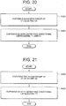
- each lens group is prepared with disposing each lens (Step S100).
- the first lens group G1 is prepared by disposing, in order from an object side, a cemented positive lens CL11 constructed by a negative meniscus lens L11 having a convex surface facing the object side cemented with a positive meniscus lens L12 having a concave surface facing the image side, and a positive meniscus lens L13 having a convex surface facing the object side.
- the second lens group G2 is prepared by disposing, in order from the object side, a negative meniscus lens L21 having a convex surface facing the object side and an aspherical surface formed on the image side, a double concave lens L22, a double convex lens L23, and a negative meniscus lens L24 having a concave surface facing the object side.
- the third lens group G3 is prepared by disposing, in order from the object side, a double convex lens L31, a cemented negative lens CL31 constructed by a double convex lens L32 cemented with a double concave lens L33, and a negative meniscus lens L34 having a concave surface facing the object side and an aspherical surface formed on the image side.
- the fourth lens group G4 is prepared by disposing, in order from the object side, a double convex lens L41 having an aspherical surface formed on the image side, a cemented negative lens CL41 constructed by a double convex lens L42 cemented with a double concave lens L43, and a double convex lens L44.
- the third lens group G3 is disposed so that the third lens group G3 may satisfy the following conditional expressions (1) and (2) (Step S200): r 3 R ⁇ 0 ⁇ 2.00 ⁇ r 3 R + r 3 F / r 3 R ⁇ r 3 F ⁇ 1.00 where r3F denotes a radius of curvature of the image side lens surface of the cemented lens CL31 in the third lens group G3, and r3R denotes a radius of curvature of the object side lens surface of the negative meniscus lens L34 in the third lens group G3.
- Fig. 1 is a view showing refractive power distribution of a zoom lens ZL according to each example of the first embodiment of the present application and movement of each lens group upon zooming from a wide-angle end state (W) to a telephoto end state (T).
- Figs. 2 , 4 , 6 , 8 , 10 and 12 are sectional views showing respective constructions of zoom lenses ZL1 through ZL6.
- each of the zoom lenses ZL1 through ZL6 is composed of, in order from an object side, a first lens group G1 having positive refractive power, a second lens group G2 having negative refractive power, a third lens group G3 having positive refractive power, a fourth lens group G4 having positive refractive power, and a filter group FL.
- the first lens group G1 is moved with respect to an image plane and the first lens group G1, the third lens group G3 and the fourth lens group G4 are moved to the object side, and the second lens group G2 is moved such that a distance between the first lens group G1 and the second lens group G2 varies, a distance between the second lens group G2 and the third lens group G3 decreases, and a distance between the third lens group G3 and the fourth lens group G4 decreases.
- the filter group FL is composed of a low-pass filter, an infrared blocking filter, and the like.
- the image plane I is formed on an unillustrated imaging device such as a film, a CCD, a DMOS, and the like.
- An aperture stop S is disposed to the most object side of the third lens group G3 and moved in a body with the third lens group G3 upon zooming from the wide-angle end state to the telephoto end state.
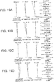
- y denotes a vertical height from the optical axis
- S(y) denotes a sag amount which is a distance along the optical axis from the tangent surface at the vertex of the aspherical surface to the aspherical surface at the vertical height "y" from the optical axis
- r denotes a radius of curvature of a reference sphere (paraxial radius of curvature)
- ⁇ denotes a conical coefficient
- An denotes an aspherical coefficient of n-th order.
- E-n denotes " ⁇ 10 -n ".
- an aspherical coefficient of the second order A2 is zero.
- Each aspherical surface is expressed in (Lens Data) by attaching "*" to the left side of the surface number.
- Fig. 2 is a sectional view showing a lens configuration of a zoom lens ZL1 according to Example 1 of the first embodiment.
- the first lens group G1 is composed of, in order from the object side, a cemented positive lens CL11 constructed by a negative meniscus lens L11 having a convex surface facing the object side cemented with a positive meniscus lens L12 having a concave surface facing the image side, and a positive meniscus lens L13 having a convex surface facing the object side.
- the second lens group G2 is composed of, in order from the object side, a negative meniscus lens L21 having a convex surface facing the object side and an aspherical surface formed on the image side, a double concave lens L22, a double convex lens L23, and a negative meniscus lens L24 having a concave surface facing the object side.
- the third lens group G3 is composed of, in order from the object side, a double convex lens L31, a cemented negative lens CL31 constructed by a double convex L32 cemented with a double concave lens L33, and a negative meniscus lens L34 having a concave surface facing the object side and an aspherical surface formed on the image side.
- the fourth lens group G4 is composed of, in order from the object side, a double convex lens L41 having an aspherical surface formed on the image side, a cemented negative lens CL41 constructed by a double convex lens L42 cemented with a double concave lens L43, and a double convex lens L44.
- W denotes a wide-angle end state
- M1 denotes a first intermediate focal length state
- M2 denotes a second intermediate focal length state
- T denotes a telephoto end state
- f denotes a focal length of the zoom lens
- FNO denotes an f-number
- 2 ⁇ denotes an angle of view
- BF denotes a back focal length
- TL denotes an air converted total lens length.
- the left most column “i” shows the lens surface number counted in order from the object side
- the third column “d” shows a distance to the next optical surface
- the total lens length "TL” denotes a distance along an optical axis between the first surface and the image plane I upon focusing on infinity.
- each of the surfaces 7, 21 and 23 is formed with an aspherical surface.
- paraxial radius of curvature "R”, a conical coefficient " ⁇ ”, and aspherical coefficient A4 through A10 are shown.
- Example 1 a distance d5 between the first lens group G1 and the second lens group G2, a distance d13 along the optical axis between the second lens group G2 and the third lens group G3, a distance d21 between the third lens group G3 and the fourth lens group G4, and a distance d28 between the fourth lens group G4 and the filter group FL are varied upon zooming.
- Values of variable distances with respect to the wide-angle end state (W), the intermediate focal length state 1 (M1), the intermediate focal length state 2 (M2), and the telephoto end state (T) are shown.
- Values for Conditional Expressions corresponding values for respective conditional expressions of the zoom lens ZL1 according to Example 1 are shown.
- fw denotes a focal length of the zoom lens ZL1 in the wide-angle end state
- f1 denotes a focal length of the first lens group G1
- f2 denotes a focal length of the second lens group G2
- f3 denotes a focal length to the third lens group G3
- f4 denotes a focal length of the fourth lens group G4
- r3F denotes a radius of curvature of the image side lens surface of the cemented negative lens CL31 in the third lens group G3
- r3R denotes a radius of curvature of the object side lens surface of the negative meniscus lens L34 in the third lens group G3.
- mm is generally used for the unit of length such as the focal length, the radius of curvature and the distance to the next lens surface.
- the unit is not necessarily to be limited to "mm", and any other suitable unit can be used.
- the explanation of reference symbols is the same in the other Examples.
- the zoom lens system according to Example 1 shows superb optical performance as a result of good corrections to various aberrations in each focal length state from the wide-angle end state through the telephoto end state.
- Fig. 4 is a sectional view showing a lens configuration of a zoom lens ZL2 according to Example 2 of the first embodiment.
- the first lens group G1 is composed of, in order from the object side, a cemented positive lens CL11 constructed by a negative meniscus lens L11 having a convex surface facing the object side cemented with a positive meniscus lens L12 having a concave surface facing the image side, and a positive meniscus lens L13 having a convex surface facing the object side.
- the second lens group G2 is composed of, in order from the object side, a negative meniscus lens L21 having a convex surface facing the object side and an aspherical surface formed on the image side, a double concave lens L22, a double convex lens L23, and a double concave lens L24.
- the third lens group G3 is composed of, in order from the object side, a double convex lens L31, a cemented negative lens CL31 constructed by a double convex L32 cemented with a double concave lens L33, and a negative meniscus lens L34 having a concave surface facing the object side and an aspherical surface formed on the image side.
- the fourth lens group G4 is composed of, in order from the object side, a double convex lens L41 having an aspherical surface formed on the image side, a cemented negative lens CL41 constructed by a double convex lens L42 cemented with a double concave lens L43, and a double convex lens L44.
- Example 2 Various values associated with the zoom lens ZL2 according to Example 2 are listed in Table 2.
- each of lens surfaces 7, 21, and 23 is formed with an aspherical surface.
- a distance d5 between the first lens group G1 and the second lens group G2 a distance d13 between the second lens group G2 and the third lens group G3, a distance d21 between the third lens group G3 and the fourth lens group G4, and a distance d28 between the fourth lens group G4 and the filter group FL are varied upon zooming.
- the zoom lens system according to Example 2 shows superb optical performance as a result of good corrections to various aberrations in each focal length state from the wide-angle end state through the telephoto end state.
- Fig. 6 is a sectional view showing a lens configuration of a zoom lens ZL3 according to Example 3 of the first embodiment.
- the first lens group G1 is composed of, in order from the object side, a cemented positive lens CL21 ( sic ) constructed by a negative meniscus lens L11 having a convex surface facing the object side cemented with a double convex lens L12, and a positive meniscus lens L13 having a convex surface facing the object side.
- the second lens group G2 is composed of, in order from the object side, a negative meniscus lens L21 having a convex surface facing the object side and an aspherical surface formed on the image side, a double concave lens L22, a double convex lens L23, and a double concave lens L24.
- the third lens group G3 is composed of, in order from the object side, a double convex lens L31, a cemented negative lens CL31 constructed by a double convex L32 cemented with a double concave lens L33, and a negative meniscus lens L34 having a concave surface facing the object side and an aspherical surface formed on the image side.
- the fourth lens group G4 is composed of, in order from the object side, a double convex lens L41 having an aspherical surface formed on the image side, a cemented negative lens CL41 constructed by a double convex lens L42 cemented with a double concave lens L43, and a positive meniscus lens L44 having a convex surface facing the image side.
- Example 3 Various values associated with the zoom lens ZL3 according to Example 3 are listed in Table 3.
- each of lens surfaces 7, 21, and 23 is formed with an aspherical surface.
- a distance d5 between the first lens group G1 and the second lens group G2, a distance d13 between the second lens group G2 and the third lens group G3, a distance d21 between the third lens group G3 and the fourth lens group G4, and a distance d28 between the fourth lens group G4 and the filter group FL are varied upon zooming.
- the zoom lens system according to Example 3 shows superb optical performance as a result of good corrections to various aberrations in each focal length state from the wide-angle end state through the telephoto end state.
- Fig. 8 is a sectional view showing a lens configuration of a zoom lens ZL4 according to Example 4 of the first embodiment.
- the first lens group G1 is composed of, in order from the object side, a cemented positive lens CL11 constructed by a negative meniscus lens L11 having a convex surface facing the object side cemented with a double convex lens L12, and a positive meniscus lens L13 having a convex surface facing the object side.
- the second lens group G2 is composed of, in order from the object side, a negative meniscus lens L21 having a convex surface facing the object side and an aspherical surface formed on the object side, a double concave lens L22, a double convex lens L23, and a double concave lens L24.
- the third lens group G3 is composed of, in order from the object side, a double convex lens L31, a cemented negative lens CL31 constructed by a double convex lens L32 cemented with a double concave lens L33, and a negative meniscus lens L34 having a concave surface facing the object side and an aspherical surface formed on the image side.
- the fourth lens group G4 is composed of, in order from the object side, a double convex lens L41 having an aspherical surface formed on the image side, a cemented negative lens CL41 constructed by a double convex lens L42 cemented with a double concave lens L43, and a positive meniscus lens L44 having a convex surface facing the image side.
- Example 4 Various values associated with the zoom lens ZL4 according to Example 4 are listed in Table 4.
- each of lens surfaces 6, 22, and 24 is formed with an aspherical surface.
- a distance d5 between the first lens group G1 and the second lens group G2, a distance d14 between the second lens group G2 and the third lens group G3, a distance d22 between the third lens group G3 and the fourth lens group G4, and a distance d29 between the fourth lens group G4 and the filter group FL are varied upon zooming.
- the zoom lens system according to Example 4 shows superb optical performance as a result of good corrections to various aberrations in each focal length state from the wide-angle end state through the telephoto end state.
- Fig. 10 is a sectional view showing a lens configuration of a zoom lens ZL5 according to Example 5 of the first embodiment.
- the first lens group G1 is composed of, in order from the object side, a cemented positive lens CL11 constructed by a negative meniscus lens L11 having a convex surface facing the object side cemented with a double convex lens L12, and a positive meniscus lens L13 having a convex surface facing the object side.
- the second lens group G2 is composed of, in order from the object side, a negative meniscus lens L21 having a convex surface facing the object side and an aspherical surface formed on the image side, a double concave lens L22, a double convex lens L23, and a double concave lens L24.
- the third lens group G3 is composed of, in order from the object side, a double convex lens L31, a cemented negative lens CL31 constructed by a double convex L32 cemented with a double concave lens L33, and a negative meniscus lens L34 having a concave surface facing the object side and an aspherical surface formed on the image side.
- the fourth lens group G4 is composed of, in order from the object side, a double convex lens L41 having an aspherical surface formed on the image side, a cemented negative lens CL41 constructed by a double convex lens L42 cemented with a double concave lens L43, and a positive meniscus lens L44 having a convex surface facing the image side.
- Example 5 Various values associated with the zoom lens ZL5 according to Example 5 are listed in Table 5.
- each of lens surfaces 7, 21, and 23 is formed with an aspherical surface.
- a distance d5 between the first lens group G1 and the second lens group G2, a distance d13 between the second lens group G2 and the third lens group G3, a distance d21 between the third lens group G3 and the fourth lens group G4, and a distance d28 between the fourth lens group G4 and the filter group FL are varied upon zooming.
- the zoom lens system according to Example 5 shows superb optical performance as a result of good corrections to various aberrations in each focal length state from the wide-angle end state through the telephoto end state.
- Fig. 12 is a sectional view showing a lens configuration of a zoom lens ZL6 according to Example 6 of the first embodiment.
- the first lens group G1 is composed of, in order from the object side, a cemented positive lens CL11 constructed by a negative meniscus lens L11 having a convex surface facing the object side cemented with a positive meniscus lens L12 having a concave surface facing the image side, and a positive meniscus lens L13 having a convex surface facing the object side.
- the second lens group G2 is composed of, in order from the object side, a negative meniscus lens L21 having a convex surface facing the object side and an aspherical surface formed on the image side, a double concave lens L22, a double convex lens L23, and a double concave lens L24.
- the third lens group G3 is composed of, in order from the object side, a double convex lens L31, a cemented negative lens CL31 constructed by a double convex L32 cemented with a double concave lens L33, and a negative meniscus lens L34 having a concave surface facing the object side and an aspherical surface formed on the image side.
- the fourth lens group G4 is composed of, in order from the object side, a double convex lens L41 having an aspherical surface formed on the image side, and a cemented negative lens CL41 constructed by a negative meniscus lens L42 having a convex surface facing the object side cemented with a double convex lens L43.
- Example 6 Various values associated with the zoom lens ZL6 according to Example 6 are listed in Table 6.
- each of lens surfaces 7, 21, and 23 is formed with an aspherical surface.
- a distance d5 between the first lens group G1 and the second lens group G2 a distance d13 between the second lens group G2 and the third lens group G3, a distance d21 between the third lens group G3 and the fourth lens group G4, and a distance d26 between the fourth lens group G4 and the filter group FL are varied upon zooming.
- the zoom lens system according to Example 6 shows superb optical performance as a result of good corrections to various aberrations in each focal length state from the wide-angle end state through the telephoto end state.
- a zoom lens ZL is composed of, in order from an object side, a first lens group G1 having positive refractive power, a second lens group G2 having negative refractive power, a third lens group G3 having positive refractive power, and a fourth lens group G4 having positive refractive power.
- the zoom lens ZL upon zooming from a wide-angle end state, which gives the shortest focal length, to a telephoto end state, which gives the longest focal length, at least the first lens group G1 and the fourth lens group G4 are moved to the object side such that a distance between the first lens group G1 and the second lens group G2 increases, a distance between the second lens group G2 and the third lens group G3 decreases, and a distance between the third lens group G3 and the fourth lens group G4 decreases.
- the zoom lens ZL makes it possible to obtain excellent optical performance with having a wide angle of view and a high zoom ratio.
- the first lens group G1 has a function of converging light rays, and is disposed near to the image as much as possible in the wide-angle end state, so that off-axis rays pass the lens group away from the optical axis, so that the diameter of the first lens group can be small.
- the first lens group is moved to the object side so as to increase a distance to the second lens group, so that converging effect is enhanced to shorten the total lens length.
- the second lens group G2 has an effect for expanding an image of the object formed by the first lens group G1, upon zooming from the wide-angle end state to the telephoto end state, the rate of expansion is enhanced by increasing the distance between the first lens group G1 and the second lens group G2 so as to vary the focal length.
- the third lens group G3 has an effect for converging the light rays diverged by the second lens group G2.
- the third lens group G3 is composed of a plurality of lens groups.
- the fourth lens group G4 has an effect for further converging light rays converged by the third lens group G3. With actively varying the distance between the third lens group G3 and the fourth lens group G4 upon zooming, variation in the image plane upon zooming can be suppressed.
- conditional expression (7) is preferably satisfied: 0.170 ⁇ ⁇ f 2 / f 3 ⁇ 0.365
- f2 denotes a focal length of the second lens group G2
- f3 denotes a focal length of the third lens group G3.
- Conditional expression (7) defines an appropriate range of the ratio of the focal length of the second lens group G2 to the focal length of the third lens group G3.
- the ratio (-f2)/f3 is equal to or exceeds the upper limit of conditional expression (7), refractive power of the second lens group G2 becomes relatively weak, so that the second lens group G2 cannot effectively contribute to zooming.
- correction of coma and curvature of field generated solely in the second lens group G2 becomes insufficient, so that it is undesirable.
- refractive power of the third lens group G3 becomes relatively strong, generation of spherical aberration and coma cannot be suppressed, so that high optical performance cannot be obtained.
- the upper limit of conditional expression (7) it is preferable to set the upper limit of conditional expression (7) to 0.350. In order to further secure the effect of the present application, it is most preferable to set the upper limit of conditional expression (7) to 0.340.
- the ratio (-f2)/f3 is equal to or falls below the lower limit of conditional expression (7), refractive power of the second lens group G2 becomes relatively strong, correction of coma in the wide-angle state becomes excessive.
- refractive power of the third lens group G3 becomes relatively weak, so that it becomes difficult to correct spherical aberration and coma generated solely in the third lens group G3. Accordingly, it is undesirable.
- the third lens group G3 is preferably constructed in the following manner.
- the third lens group G3 is composed of, in order from the object side, a positive lens L31, a cemented lens CL31 constructed by a positive lens L32 cemented with a negative lens L33, and a negative lens L34.
- an aperture stop S is disposed between the second lens group G2 and the third lens group G3, and moved in a body with the third lens group G3 upon zooming from the wide-angle end state to the telephoto end state.
- the third lens group G3 is preferably constructed in the following manner.
- the positive lens L31 in the third lens group G3 has a convex surface facing the object side
- the positive lens L32 in the cemented lens CL31 has a convex surface facing the object side and cemented with the negative lens L33 having a concave surface facing the image side
- the negative lens L34 is a negative meniscus lens and has a convex surface facing the image side.
- the following conditional expression (3) is preferable satisfied: 0.10 ⁇ fw / f 3 ⁇ 0.50 where fw denotes a focal length of the zoom lens in the wide-angle end state, and f3 denotes a focal length of the third lens group G3.
- Conditional expression (3) defines the focal length of the third lens group G3.
- the ratio fw/f3 is equal to or exceeds the upper limit of conditional expression (3), refractive power of the third lens group G3 becomes strong, and spherical aberration generated solely in the third lens group G3 increases, so that it is undesirable.
- conditional expression (4) is preferably satisfied: 6.00 ⁇ f 1 / ⁇ f 2 ⁇ 7.80 where f1 denotes a focal length of the first lens group G1, and f2 denotes a focal length of the second lens group G2.
- Conditional expression (4) defines an appropriate range of a ratio of the focal length of the first lens group G1 to the focal length of the second lens group G2. However, conditional expression (4) has already explained above, so that duplicated explanations are omitted.
- the third lens group G3 is composed of in the following manner.
- the cemented lens CL31 constructed by the positive lens L32 having the convex surface facing the object side cemented with the negative lens L33 having the concave surface facing the image side in the third lens group G3 has negative refractive power. With disposing negative refractive power in this manner, refractive power distribution in the third lens group G3 becomes proper, so that spherical aberration and curvature of field generated solely in the third lens group can be excellently corrected.
- the third lens group G3 preferably includes at least one aspherical lens. With disposing an aspherical lens in the third lens group G3, it becomes possible to excellently correct coma and curvature of field generated solely in the third lens group G3.
- the image side lens surface of the negative lens L34 disposed to the image side of the cemented lens CL31 in the third lens group G3 is formed as an aspherical surface.
- conditional expression (5) is preferably satisfied: 0.15 ⁇ f 3 / f 4 ⁇ 2.75
- f3 denotes a focal length of the third lens group G3
- f4 denotes a focal length of the fourth lens group G4.
- Conditional expression (5) defines an appropriate range of the ratio of the focal length of the third lens group G3 to the focal length of the fourth lens group G4.
- conditional expression (5) has already explained above, so that duplicated explanations are omitted.
- conditional expression (6) is preferably satisfied: 0.85 ⁇ f 1 / f 3 ⁇ 2.74 where f1 denotes a focal length of the first lens group G1, and f3 denotes a focal length of the third lens group G3.
- Conditional expression (6) defines an appropriate range of the ratio of the focal length of the first lens group G1 to the focal length of the third lens group G3. However, conditional expression (6) has already explained above, so that duplicated explanations are omitted.
- each lens group is prepared with disposing each lens (Step S300).
- the first lens group G1 is prepared by disposing, in order from an object side, a cemented positive lens CL11 constructed by a negative meniscus lens L11 having a convex surface facing the object side cemented with a positive meniscus lens L12 having a concave surface facing the image side, and a positive meniscus lens L13 having a convex surface facing the object side.
- the second lens group G2 is prepared by disposing, in order from the object side, a negative meniscus lens L21 having a convex surface facing the object side and an aspherical surface formed on the image side, a double concave lens L22, a double convex lens L23, and a negative meniscus lens L24 having a concave surface facing the object side.
- the third lens group G3 is prepared by disposing, in order from the object side, a double convex lens L31, a cemented negative lens CL31 constructed by a double convex lens L32 cemented with a double concave lens L33, and a negative meniscus lens L34 having a concave surface facing the object side and an aspherical surface formed on the image side.
- the fourth lens group G4 is prepared by disposing, in order from the object side, a double convex lens L41 having an aspherical surface formed on the image side, a cemented negative lens CL41 constructed by a double convex lens L42 cemented with a double concave lens L43, and a double convex lens L44.
- the third lens group G3 is disposed so that the third lens group G3 may satisfy the following conditional expression (7) (Step S400): 0.170 ⁇ ⁇ f 2 / f 3 ⁇ 0.365 where f2 denotes a focal length of the second lens group G2, and f3 denotes a focal length of the third lens group G3.
- Fig. 1 is a view showing refractive power distribution of a zoom lens ZL according to each example of the illustrative example of the present application and movement of each lens group upon zooming from a wide-angle end state (W) to a telephoto end state (T).
- Figs. 2 , 4 , 14 , 6 , 8 , 16 , 18 and 12 are sectional views showing respective constructions of zoom lenses ZL7 through ZL14.
- each of the zoom lenses ZL7 through ZL14 is composed of, in order from an object side, a first lens group G1 having positive refractive power, a second lens group G2 having negative refractive power, a third lens group G3 having positive refractive power, a fourth lens group G4 having positive refractive power, and a filter group FL.
- the first lens group G1 is moved with respect to an image plane and the first lens group G1, the third lens group G3 and the fourth lens group G4 are moved to the object side, and the second lens group G2 is moved such that a distance between the first lens group G1 and the second lens group G2 varies, a distance between the second lens group G2 and the third lens group G3 decreases, and a distance between the third lens group G3 and the fourth lens group G4 decreases.
- the filter group FL is composed of a low-pass filter, an infrared blocking filter, and the like.
- the image plane I is formed on an unillustrated imaging device such as a film, a CCD, a DMOS, and the like.
- An aperture stop S is disposed to the most object side of the third lens group G3 and moved in a body with the third lens group G3 upon zooming from the wide-angle end state to the telephoto end state.
- Fig. 2 is a sectional view showing a lens configuration of a zoom lens ZL1 according to Example 7 of the illustrative example.
- the first lens group G1 is composed of, in order from the object side, a cemented positive lens CL11 constructed by a negative meniscus lens L11 having a convex surface facing the object side cemented with a positive meniscus lens L12 having a concave surface facing the image side, and a positive meniscus lens L13 having a convex surface facing the object side.
- the second lens group G2 is composed of, in order from the object side, a negative meniscus lens L21 having a convex surface facing the object side and an aspherical surface formed on the image side, a double concave lens L22, a double convex lens L23, and a negative meniscus lens L24 having a concave surface facing the object side.
- the third lens group G3 is composed of, in order from the object side, a double convex lens L31, a cemented negative lens CL31 constructed by a double convex L32 cemented with a double concave lens L33, and a negative meniscus lens L34 having a concave surface facing the object side and an aspherical surface formed on the image side.
- the fourth lens group G4 is composed of, in order from the object side, a double convex lens L41 having an aspherical surface formed on the image side, a cemented negative lens CL41 constructed by a double convex lens L42 cemented with a double concave lens L43, and a double convex lens L44.
- Example 7 Various values associated with the zoom lens ZL7 according to Example 7 are listed in Table 7.
- each of lens surfaces 7, 21, and 23 is formed with an aspherical surface.
- a distance d5 between the first lens group G1 and the second lens group G2 a distance d13 between the second lens group G2 and the third lens group G3, a distance d21 between the third lens group G3 and the fourth lens group G4, and a distance d28 between the fourth lens group G4 and the filter group FL are varied upon zooming.
- the zoom lens system according to Example 7 shows superb optical performance as a result of good corrections to various aberrations in each focal length state from the wide-angle end state through the telephoto end state.
- Fig. 4 is a sectional view showing a lens configuration of a zoom lens ZL8 according to Example 8 of the illustrative example.
- the first lens group G1 is composed of, in order from the object side, a cemented positive lens CL11 constructed by a negative meniscus lens L11 having a convex surface facing the object side cemented with a positive meniscus lens L12 having a concave surface facing the image side, and a positive meniscus lens L13 having a convex surface facing the object side.
- the second lens group G2 is composed of, in order from the object side, a negative meniscus lens L21 having a convex surface facing the object side and an aspherical surface formed on the image side, a double concave lens L22, a double convex lens L23, and a double concave lens L24.
- the third lens group G3 is composed of, in order from the object side, a double convex lens L31, a cemented negative lens CL31 constructed by a double convex L32 cemented with a double concave lens L33, and a negative meniscus lens L34 having a concave surface facing the object side and an aspherical surface formed on the image side.
- the fourth lens group G4 is composed of, in order from the object side, a double convex lens L41 having an aspherical surface formed on the image side, a cemented negative lens CL41 constructed by a double convex lens L42 cemented with a double concave lens L43, and a double convex lens L44.
- Example 8 Various values associated with the zoom lens ZL8 according to Example 8 are listed in Table 8.
- each of lens surfaces 7, 21, and 23 is formed with an aspherical surface.
- a distance d5 between the first lens group G1 and the second lens group G2 a distance d13 between the second lens group G2 and the third lens group G3, a distance d21 between the third lens group G3 and the fourth lens group G4, and a distance d28 between the fourth lens group G4 and the filter group FL are varied upon zooming.
- the zoom lens system according to Example 8 shows superb optical performance as a result of good corrections to various aberrations in each focal length state from the wide-angle end state through the telephoto end state.
- Fig. 14 is a sectional view showing a lens configuration of a zoom lens ZL9 according to Example 9 of the illustrative example.
- the first lens group G1 is composed of, in order from the object side, a cemented positive lens CL11 constructed by a negative meniscus lens L11 having a convex surface facing the object side cemented with a double convex lens L12, and a positive meniscus lens L13 having a convex surface facing the object side.
- the second lens group G2 is composed of, in order from the object side, a negative meniscus lens L21 having a convex surface facing the object side and an aspherical surface formed on the image side, a double concave lens L22, a double convex lens L23, and a double concave lens L24.
- the third lens group G3 is composed of, in order from the object side, a double convex lens L31, a cemented negative lens CL31 constructed by a double convex L32 cemented with a double concave lens L33, and a negative meniscus lens L34 having a concave surface facing the object side and an aspherical surface formed on the image side.
- the fourth lens group G4 is composed of, in order from the object side, a double convex lens L41 having an aspherical surface formed on the image side, a cemented negative lens CL41 constructed by a double convex lens L42 cemented with a double concave lens L43, and a double convex lens L44.
- Example 9 Various values associated with the zoom lens ZL9 according to Example 9 are listed in Table 9.
- each of lens surfaces 7, 21, and 23 is formed with an aspherical surface.
- a distance d5 between the first lens group G1 and the second lens group G2, a distance d13 between the second lens group G2 and the third lens group G3, a distance d21 between the third lens group G3 and the fourth lens group G4, and a distance d28 between the fourth lens group G4 and the filter group FL are varied upon zooming.
- the zoom lens system according to Example 9 shows superb optical performance as a result of good corrections to various aberrations in each focal length state from the wide-angle end state through the telephoto end state.
- Fig. 6 is a sectional view showing a lens configuration of a zoom lens ZL10 according to Example 10 of the illustrative example.
- the first lens group G1 is composed of, in order from the object side, a cemented positive lens CL21 ( sic ) constructed by a negative meniscus lens L11 having a convex surface facing the object side cemented with a double convex lens L12, and a positive meniscus lens L13 having a convex surface facing the object side.
- the second lens group G2 is composed of, in order from the object side, a negative meniscus lens L21 having a convex surface facing the object side and an aspherical surface formed on the image side, a double concave lens L22, a double convex lens L23, and a double concave lens L24.
- the third lens group G3 is composed of, in order from the object side, a double convex lens L31, a cemented negative lens CL31 constructed by a double convex L32 cemented with a double concave lens L33, and a negative meniscus lens L34 having a concave surface facing the object side and an aspherical surface formed on the image side.
- the fourth lens group G4 is composed of, in order from the object side, a double convex lens L41 having an aspherical surface formed on the image side, a cemented negative lens CL41 constructed by a double convex lens L42 cemented with a double concave lens L43, and a positive meniscus lens L44 having a convex surface facing the image side.
- Example 10 Various values associated with the zoom lens ZL10 according to Example 10 are listed in Table 10.
- each of lens surfaces 7, 21, and 23 is formed with an aspherical surface.
- a distance d5 between the first lens group G1 and the second lens group G2 a distance d13 between the second lens group G2 and the third lens group G3, a distance d21 between the third lens group G3 and the fourth lens group G4, and a distance d28 between the fourth lens group G4 and the filter group FL are varied upon zooming.
- the zoom lens system according to Example 10 shows superb optical performance as a result of good corrections to various aberrations in each focal length state from the wide-angle end state through the telephoto end state.
- Fig. 8 is a sectional view showing a lens configuration of a zoom lens ZL11 according to Example 11 of the illustrative example.
- the first lens group G1 is composed of, in order from the object side, a cemented positive lens CL11 constructed by a negative meniscus lens L11 having a convex surface facing the object side cemented with a double convex lens L12, and a positive meniscus lens L13 having a convex surface facing the object side.
- the second lens group G2 is composed of, in order from the object side, a negative meniscus lens L21 having a convex surface facing the object side and an aspherical surface formed on the object side, a double concave lens L22, a double convex lens L23, and a double concave lens L24.
- the third lens group G3 is composed of, in order from the object side, a double convex lens L31, a cemented negative lens CL31 constructed by a double convex lens L32 cemented with a double concave lens L33, and a negative meniscus lens L34 having a concave surface facing the object side and an aspherical surface formed on the image side.
- the fourth lens group G4 is composed of, in order from the object side, a double convex lens L41 having an aspherical surface formed on the image side, a cemented negative lens CL41 constructed by a double convex lens L42 cemented with a double concave lens L43, and a positive meniscus lens L44 having a convex surface facing the image side.
- Example 11 Various values associated with the zoom lens ZL11 according to Example 11 are listed in Table 11.
- each of lens surfaces 6, 22, and 24 is formed with an aspherical surface.
- a distance d5 between the first lens group G1 and the second lens group G2, a distance d14 between the second lens group G2 and the third lens group G3, a distance d22 between the third lens group G3 and the fourth lens group G4, and a distance d29 between the fourth lens group G4 and the filter group FL are varied upon zooming.
- the zoom lens system according to Example 11 shows superb optical performance as a result of good corrections to various aberrations in each focal length state from the wide-angle end state through the telephoto end state.
- Fig. 16 is a sectional view showing a lens configuration of a zoom lens ZL12 according to Example 12 of the illustrative example.
- the first lens group G1 is composed of, in order from the object side, a cemented positive lens CL11 constructed by a negative meniscus lens L11 having a convex surface facing the object side cemented with a double convex lens L12, and a positive meniscus lens L13 having a convex surface facing the object side.
- the second lens group G2 is composed of, in order from the object side, a negative meniscus lens L21 having a convex surface facing the object side and an aspherical surface formed on the object side, a double concave lens L22, a double convex lens L23, and a double concave lens L24.
- the third lens group G3 is composed of, in order from the object side, a double convex lens L31, a cemented positive lens CL31 constructed by a double convex L32 cemented with a negative meniscus lens L33 having a convex surface facing the image side, and a negative meniscus lens L34 having a concave surface facing the object side and an aspherical surface formed on the image side.
- the fourth lens group G4 is composed of, in order from the object side, a double convex lens L41 having an aspherical surface formed on the image side, a cemented negative lens CL41 constructed by a double convex lens L42 cemented with a double concave lens L43, and a positive meniscus lens L44 having a convex surface facing the image side.
- Example 12 Various values associated with the zoom lens ZL12 according to Example 12 are listed in Table 12.
- each of lens surfaces 7, 21, and 23 is formed with an aspherical surface.
- a distance d5 between the first lens group G1 and the second lens group G2 a distance d13 between the second lens group G2 and the third lens group G3, a distance d21 between the third lens group G3 and the fourth lens group G4, and a distance d28 between the fourth lens group G4 and the filter group FL are varied upon zooming.
- the zoom lens system according to Example 12 shows superb optical performance as a result of good corrections to various aberrations in each focal length state from the wide-angle end state through the telephoto end state.
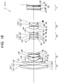
- Fig. 18 is a sectional view showing a lens configuration of a zoom lens ZL13 according to Example 13 of the illustrative example.
- the first lens group G1 is composed of, in order from the object side, a cemented positive lens CL11 constructed by a negative meniscus lens L11 having a convex surface facing the object side cemented with a double convex lens L12, and a positive meniscus lens L13 having a convex surface facing the object side.
- the second lens group G2 is composed of, in order from the object side, a negative meniscus lens L21 having a convex surface facing the object side and an aspherical surface formed on the object side, a double concave lens L22, a double convex lens L23, and a double concave lens L24.
- the third lens group G3 is composed of, in order from the object side, a double convex lens L31, a cemented positive lens CL31 constructed by a double convex L32 cemented with a negative meniscus lens L33 having a convex surface facing the image side, and a negative meniscus lens L34 having a concave surface facing the object side and an aspherical surface formed on the image side.
- the fourth lens group G4 is composed of, in order from the object side, a double convex lens L41 having an aspherical surface formed on the image side, and a cemented negative lens CL41 constructed by a negative meniscus lens L42 having a convex surface facing the object side cemented with a double convex lens L43.
- Example 13 Various values associated with the zoom lens ZL13 according to Example 13 are listed in Table 13.
- each of lens surfaces 7, 21, and 23 is formed with an aspherical surface.
- a distance d5 between the first lens group G1 and the second lens group G2 a distance d13 between the second lens group G2 and the third lens group G3, a distance d21 between the third lens group G3 and the fourth lens group G4, and a distance d26 between the fourth lens group G4 and the filter group FL are varied upon zooming.
- the zoom lens system according to Example 13 shows superb optical performance as a result of good corrections to various aberrations in each focal length state from the wide-angle end state through the telephoto end state.
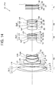
- Fig. 12 is a sectional view showing a lens configuration of a zoom lens ZL14 according to Example 14 of the illustrative example.
- the first lens group G1 is composed of, in order from the object side, a cemented positive lens CL11 constructed by a negative meniscus lens L11 having a convex surface facing the object side cemented with a positive meniscus lens L12 having a concave surface facing the image side, and a positive meniscus lens L13 having a convex surface facing the object side.
- the second lens group G2 is composed of, in order from the object side, a negative meniscus lens L21 having a convex surface facing the object side and an aspherical surface formed on the image side, a double concave lens L22, a double convex lens L23, and a double concave lens L24.
- the third lens group G3 is composed of, in order from the object side, a double convex lens L31, a cemented negative lens CL31 constructed by a double convex L32 cemented with a double concave lens L33, and a negative meniscus lens L34 having a concave surface facing the object side and an aspherical surface formed on the image side.
- the fourth lens group G4 is composed of, in order from the object side, a double convex lens L41 having an aspherical surface formed on the image side, and a cemented negative lens CL41 constructed by a negative meniscus lens L42 having a convex surface facing the object side cemented with a double convex lens L43.
- Example 14 Various values associated with the zoom lens ZL14 according to Example 14 are listed in Table 14.
- each of lens surfaces 7, 21, and 23 is formed with an aspherical surface.
- a distance d5 between the first lens group G1 and the second lens group G2, a distance d13 between the second lens group G2 and the third lens group G3, a distance d21 between the third lens group G3 and the fourth lens group G4, and a distance d26 between the fourth lens group G4 and the filter group FL are varied upon zooming.
- the zoom lens system according to Example 14 shows superb optical performance as a result of good corrections to various aberrations in each focal length state from the wide-angle end state through the telephoto end state.
- Fig. 22 is a sectional view showing a construction of a single-lens reflex digital camera 1 (hereinafter simply called as a camera) as an optical apparatus equipped with the zoom lens ZL according to each embodiment of the present application.
- a camera single-lens reflex digital camera 1
- light rays emitted from an unillustrated object are converged by the imaging lens 2 (zoom lens ZL), reflected by a quick return mirror 3, and focused on a focusing screen 4.
- the light rays focused on the focusing screen 4 are reflected a plurality of times in a pentagonal roof prism 5, and led to an eyepiece 6. Accordingly, a photographer can observe the object (the object to be photographed) image as an erected image through the eyepiece 6.
- the quick return mirror 3 When the photographer presses an unillustrated release button all the way down, the quick return mirror 3 is retracted from the optical path, and the light rays from the unillustrated object are formed an object image on an imaging device 7. Accordingly, the light rays emitted from the object are captured by the imaging device 7, and stored in an unillustrated memory as a photographed image of the object(the object to be photographed). In this manner, the photographer can take a picture of an object (the object to be photographed) by the camera 1.
- the camera 1 shown in Fig. 22 may be constructed to removably hold the zoom lens ZL and may also be constructed integrally with the zoom lens ZL.
- the camera 1 may be constructed as a so-called single lens reflex camera and may also be constructed as a compact camera including none of the quick return mirror.
- a camera-shake detector for detecting vibrations of a lens system and a driving means are connected to the lens system, a lens group or a portion of a lens group composing the lens system disposed as a shift lens group, and the shift lens group is shifted by the drive means for correcting an image blur (movement of the image) caused by vibration of the lens system detected by the camera-shake detector, so that the image blur can be corrected.
- the zoom lens ZL can be functioned as a vibration reduction lens system.
- a lens configuration in which a lens or a lens group is added to the most object side and a lens configuration in which a lens or a lens group is added to the most image side may be possible.
- a lens configuration in which a lens or a lens group is added between lens groups is also possible.
- a lens group is defined as a portion having at least one lens that is separated from the other portions by air spaces that vary upon zooming.
- a single lens group, a plurality of lens groups, or a sub-lens group may be moved along the optical axis as a focusing lens group.
- the focusing lens group can be used for auto focus, and suitable for being driven by a motor such as an ultrasonic motor. It is particularly preferable that at least a portion of the second lens group G2, or at least a portion of the fourth lens group G4 is used as the focusing lens group.
- any lens surface in a zoom lens system according to the present application may be formed as a spherical surface, a plane surface or an aspherical surface.
- a lens surface is a spherical surface or a plane surface, processing and assembling become easy, so that deterioration of optical performance caused by errors upon processing and assembling can be prevented. Even if the image plane is shifted, deterioration in optical performance is small, so that it is desirable.
- the aspherical surface may be fabricated by a fine grinding process, a glass molding process that a glass material is formed into an aspherical shape by a mold, or a compound type process that a resin material is formed into an aspherical shape on a glass surface.
- Any lens surface may be a diffractive optical surface.
- Any lens may be a graded index lens (GRIN lens), or a plastic lens.
- an aperture stop S is preferably disposed between the second lens group G2 and the third lens group G3, the function may be substituted by a lens frame without disposing a member as an aperture stop.
- An antireflection coating having high transmittance over a broad wavelength range may be applied to each lens surface in a zoom lens ZL according to the present application to reduce flare or ghost images, so that high optical performance with a high contrast can be achieved.
- the first lens group G1 includes two positive lens components. In the first lens group G1, it is preferable that these lens components are disposed, in order from the object side, positive-positive with an air space between them. Alternatively, the first lens group G1 preferably includes two positive lens components and one negative lens component. In the first lens group G1, it is preferable that these lens components are disposed, in order from the object side, negative-positive-positive with air spaces between them.
- the second lens group G2 includes one positive lens component and two negative lens components.
- these lens components are disposed, in order from the object side, negative-negative-positive with disposing air spaces between them.
- the second lens group G2 preferably includes one positive lens component and three negative lens components.
- these lens components are disposed, in order from the object side, negative-negative-positive-negative with disposing air spaces between them.
- the third lens group G3 includes one positive lens component and two negative lens components.
- these lens components are disposed, in order from the object side, positive-negative-negative with disposing air spaces between them.
- the fourth lens group G4 includes two positive lens components and one negative lens component. In the fourth lens group G4, it is preferable that these lens components are disposed, in order from the object side, positive-negative-positive with disposing air spaces between them. Otherwise, the fourth lens group G4 preferably includes one positive lens component and one negative lens component. In the fourth lens group G4, it is preferable that these lens components are disposed, in order from the object side, positive-negative with disposing an air space between them.
- the zoom ratio is about five to fifteen.
- a distance between the image side lens surface of the most image side lens and the image plane, which is the back focal length, is preferably 10 to 30mm in the smallest state.
- an image height is preferable 5 to 12.5mm, and most preferable 5 to 9.5mm.
Claims (12)
- Zoomlinse (ZL), die in der Reihenfolge von einer Objektseite aus Folgendem besteht:einer ersten Linsengruppe (G1), die eine positive Brechkraft aufweist;einer zweiten Linsengruppe (G2), die eine negative Brechkraft aufweist;einer dritten Linsengruppe (G3), die eine positive Brechkraft aufweist; undeiner vierten Linsengruppe (G4), die eine positive Brechkraft aufweist,wobei die dritte Linsengruppe (G3) in der Reihenfolge von der Objektseite aus Folgendem besteht: einer ersten positiven Linse (L31), die eine konvexe Oberfläche aufweist, welche der Objektseite zugewandt ist, einer verkitteten Linse (CL31),konstruiert aus einer zweiten positiven Linse (L32), die eine konvexe Oberfläche aufweist, welche der Objektseite zugewandt ist, und verkittet mit einer bikonkaven negativen Linse (L33), die eine konkave Oberfläche aufweist, welche der Bildseite zugewandt ist, und einer negativen Meniskuslinse (L34) neben der negativen Linse (L33) der verkitteten Linse (CL31), wobei die negative Meniskuslinse (L34) eine konvexe Oberfläche aufweist, die der Bildseite zugewandt ist, unddie folgenden konditionalen Ausdrücke erfüllt werden:


- Zoomlinse nach Anspruch 1, wobei der folgende konditionale Ausdruck erfüllt wird:

- Zoomlinse nach Anspruch 1, wobei beim Zoomen von einem Weitwinkelendzustand in einen Teleobjektivendzustand mindestens die erste Linsengruppe (G1) und die vierte Linsengruppe (G4) zu der Objektseite bewegt werden, sodass sich eine Entfernung zwischen der ersten Linsengruppe (G1) und der zweiten Linsengruppe (G2) verändert, sich eine Entfernung zwischen der zweiten Linsengruppe (G2) und der dritten Linsengruppe (G3) verändert und sich eine Entfernung zwischen der dritten Linsengruppe (G3) und der vierten Linsengruppe (G4) verändert.
- Zoomlinse nach Anspruch 1, wobei sich beim Zoomen von einem Weitwinkelendzustand in einen Teleobjektivendzustand eine Entfernung zwischen der ersten Linsengruppe (G1) und der zweiten Linsengruppe (G2) vergrößert, sich eine Entfernung zwischen der zweiten Linsengruppe (G2) und der dritten Linsengruppe (G3) verringert und sich eine Entfernung zwischen der dritten Linsengruppe (G3) und der vierten Linsengruppe (G4) verringert.
- Zoomlinse nach Anspruch 1, wobei der folgende konditionale Ausdruck erfüllt wird:

- Zoomlinse nach Anspruch 1, wobei zwischen der zweiten Linsengruppe (G2) und der dritten Linsengruppe (G3) eine Aperturblende (S) angeordnet ist.
- Zoomlinse nach Anspruch 1, wobei die verkittete Linse (CL31) in der dritten Linsengruppe (G3) eine negative Brechkraft aufweist.
- Zoomlinse nach Anspruch 1, wobei die dritte Linsengruppe (G3) mindestens eine asphärische Linse beinhaltet.
- Zoomlinse nach Anspruch 1, wobei eine Bildseitenlinsenoberfläche der negativen Meniskuslinse, die zu der Bildseite der verkitteten Linse in der dritten Linsengruppe (G3) angeordnet ist, als eine asphärische Oberfläche gebildet ist.
- Zoomlinse nach Anspruch 1, wobei mindestens ein Abschnitt der zweiten Linsengruppe (G2) entlang einer optischen Achse bewegt wird, wodurch Fokussierung auf ein nahes Objekt durchgeführt wird.
- Zoomlinse nach Anspruch 1, wobei mindestens ein Abschnitt der dritten Linsengruppe (G3) in einer Richtung, beinhaltend eine Komponente, senkrecht zu einer optischen Achse bewegt wird.
- Optische Vorrichtung, die mit der Zoomlinse (ZL) nach Anspruch 1 ausgestattet ist, zum Bilden eines Bilds eines Objekts auf einer gegebenen Bildebene (I).
Applications Claiming Priority (3)
| Application Number | Priority Date | Filing Date | Title |
|---|---|---|---|
| JP2009013721A JP5240663B2 (ja) | 2009-01-24 | 2009-01-24 | ズームレンズ、このズームレンズを備えた光学機器、及び、ズームレンズの製造方法 |
| JP2009013720A JP5240662B2 (ja) | 2009-01-24 | 2009-01-24 | ズームレンズ、このズームレンズを備えた光学機器、及び、ズームレンズの製造方法 |
| PCT/JP2009/070086 WO2010084664A1 (ja) | 2009-01-24 | 2009-11-24 | ズームレンズ、ズームレンズを備えた光学機器、及び、ズームレンズの製造方法 |
Publications (3)
| Publication Number | Publication Date |
|---|---|
| EP2390705A1 EP2390705A1 (de) | 2011-11-30 |
| EP2390705A4 EP2390705A4 (de) | 2014-09-03 |
| EP2390705B1 true EP2390705B1 (de) | 2018-08-01 |
Family
ID=42355732
Family Applications (1)
| Application Number | Title | Priority Date | Filing Date |
|---|---|---|---|
| EP09838854.9A Not-in-force EP2390705B1 (de) | 2009-01-24 | 2009-11-24 | Zoom-linse, mit zoom-linse ausgestattete optische einrichtung und verfahren zur herstellung einer zoom-linse |
Country Status (4)
| Country | Link |
|---|---|
| US (1) | US8619373B2 (de) |
| EP (1) | EP2390705B1 (de) |
| CN (1) | CN102292660B (de) |
| WO (1) | WO2010084664A1 (de) |
Families Citing this family (5)
| Publication number | Priority date | Publication date | Assignee | Title |
|---|---|---|---|---|
| CN104011578B (zh) | 2011-12-27 | 2016-03-09 | 富士胶片株式会社 | 变焦透镜以及摄像装置 |
| CN104769478B (zh) * | 2012-11-08 | 2017-04-05 | 富士胶片株式会社 | 变焦透镜以及摄像装置 |
| US20160004053A1 (en) * | 2013-02-13 | 2016-01-07 | Tamron Co., Ltd. | Zoom Lens |
| US10156707B2 (en) * | 2013-08-09 | 2018-12-18 | Nikon Corporation | Zoom lens, optical apparatus and method for manufacturing the zoom lens |
| CN106772965B (zh) * | 2017-01-22 | 2018-12-11 | 嘉兴中润光学科技有限公司 | 一种变焦距镜头 |
Family Cites Families (16)
| Publication number | Priority date | Publication date | Assignee | Title |
|---|---|---|---|---|
| US4763998A (en) | 1985-06-26 | 1988-08-16 | Canon Kabushiki Kaisha | Compact zoom lens |
| JPS61296319A (ja) | 1985-06-26 | 1986-12-27 | Canon Inc | 小型のズ−ムレンズ |
| JPS6385518A (ja) | 1986-09-29 | 1988-04-16 | Canon Inc | 小型のズ−ムレンズ |
| JPS63247715A (ja) | 1987-04-03 | 1988-10-14 | Canon Inc | ズ−ムレンズ |
| JPH01142519A (ja) | 1987-11-27 | 1989-06-05 | Minolta Camera Co Ltd | 有限距離用ズームレンズ |
| JPH07113957A (ja) * | 1993-10-19 | 1995-05-02 | Minolta Co Ltd | インナーフォーカス式ズームレンズ |
| JP3376142B2 (ja) | 1994-12-21 | 2003-02-10 | キヤノン株式会社 | ズームレンズ |
| JP3376143B2 (ja) | 1994-12-21 | 2003-02-10 | キヤノン株式会社 | ズームレンズ |
| JPH11352400A (ja) | 1998-06-08 | 1999-12-24 | Minolta Co Ltd | ズームレンズ系 |
| JP4146977B2 (ja) * | 1999-12-10 | 2008-09-10 | キヤノン株式会社 | ズームレンズ |
| JP4366932B2 (ja) * | 2002-12-20 | 2009-11-18 | 株式会社ニコン | ズームレンズ |
| JP2006350049A (ja) * | 2005-06-17 | 2006-12-28 | Konica Minolta Photo Imaging Inc | レンズユニット、およびそれを備える撮像装置 |
| JP4821207B2 (ja) * | 2005-08-02 | 2011-11-24 | コニカミノルタオプト株式会社 | 変倍光学系、およびそれを備えた撮像装置 |
| JP4907169B2 (ja) | 2005-12-28 | 2012-03-28 | 株式会社リコー | ズームレンズ,カメラ装置および携帯情報端末装置 |
| EP2128676B1 (de) * | 2006-07-20 | 2016-08-17 | Nikon Corporation | Vibrationsbeständiges Telezoomobjektiv mit vier Linsengruppen |
| JP5126663B2 (ja) * | 2007-11-02 | 2013-01-23 | 株式会社ニコン | ズームレンズ及びこのズームレンズを備えた光学機器 |
-
2009
- 2009-11-24 WO PCT/JP2009/070086 patent/WO2010084664A1/ja active Application Filing
- 2009-11-24 EP EP09838854.9A patent/EP2390705B1/de not_active Not-in-force
- 2009-11-24 CN CN200980155379.0A patent/CN102292660B/zh not_active Expired - Fee Related
- 2009-11-24 US US13/145,944 patent/US8619373B2/en active Active
Non-Patent Citations (1)
| Title |
|---|
| None * |
Also Published As
| Publication number | Publication date |
|---|---|
| US8619373B2 (en) | 2013-12-31 |
| EP2390705A1 (de) | 2011-11-30 |
| US20110286108A1 (en) | 2011-11-24 |
| CN102292660A (zh) | 2011-12-21 |
| WO2010084664A1 (ja) | 2010-07-29 |
| CN102292660B (zh) | 2014-07-16 |
| EP2390705A4 (de) | 2014-09-03 |
Similar Documents
| Publication | Publication Date | Title |
|---|---|---|
| EP2360504B1 (de) | Zoomobjektivsystem, optische Vorrichtung und Verfahren zur Herstellung eines Zoomobjektivsystems | |
| EP2620796B1 (de) | Optisches System und Bildgebungsvorrichtung | |
| EP2397881B1 (de) | Retrofokus Zoomobjektiv mit vier Linsengruppen | |
| EP2362259B1 (de) | Makro-Teleobjektiv mit drei Linsengruppen vom Frontfokus-Typ und Verfahren zu seiner Herstellung | |
| EP2045637B1 (de) | Zoomobjektivsystem | |
| EP2128676B1 (de) | Vibrationsbeständiges Telezoomobjektiv mit vier Linsengruppen | |
| EP2045639A1 (de) | Optisches system mit variabler leistung, abbildungsvorrichtung und verfahren zur variierung der vergrösserung eines optischen systems mit variabler leistung | |
| US8144403B2 (en) | Zoom lens system, optical apparatus, and method for zooming | |
| CN108490592B (zh) | 变焦光学系统 | |
| EP1998204B1 (de) | Vibrationsbeständiges Telezoomobjektiv mit vier Linsengruppen vom Hinterfokus-Typ | |
| EP1870760A1 (de) | Retrofokus Zoom Objektiv mit vier Linsengruppen | |
| EP3252519B1 (de) | Zoomobjektiv, optische vorrichtung und zoomobjektivherstellungsverfahren | |
| EP2325682A2 (de) | Optisches System, optische Vorrichtung und Verfahren zur Herstellung eines optischen Systems | |
| JP4847091B2 (ja) | ズームレンズ及びそれを有する撮像装置 | |
| EP2390705B1 (de) | Zoom-linse, mit zoom-linse ausgestattete optische einrichtung und verfahren zur herstellung einer zoom-linse | |
| EP2020613A2 (de) | Optisches System | |
| EP2015122A1 (de) | Zoomobjektiv und optische vorrichtung damit | |
| EP2071380B1 (de) | Zoomobjektivsystem, optisches Gerät und Verfahren zur Herstellung eines Zoomobjektivsystems | |
| CN113366362B (zh) | 变倍光学系统以及光学设备 | |
| JPH0933808A (ja) | ズームレンズ | |
| JP5115871B2 (ja) | ズームレンズ、光学機器及びズームレンズの製造方法 | |
| JP2011069888A (ja) | ズームレンズ、光学機器及びズームレンズの製造方法 | |
| JP2008015432A (ja) | ズームレンズと、これを有する光学機器 |
Legal Events
| Date | Code | Title | Description |
|---|---|---|---|
| PUAI | Public reference made under article 153(3) epc to a published international application that has entered the european phase |
Free format text: ORIGINAL CODE: 0009012 |
|
| 17P | Request for examination filed |
Effective date: 20110823 |
|
| AK | Designated contracting states |
Kind code of ref document: A1 Designated state(s): AT BE BG CH CY CZ DE DK EE ES FI FR GB GR HR HU IE IS IT LI LT LU LV MC MK MT NL NO PL PT RO SE SI SK SM TR |
|
| DAX | Request for extension of the european patent (deleted) | ||
| REG | Reference to a national code |
Ref country code: DE Ref legal event code: R079 Ref document number: 602009053638 Country of ref document: DE Free format text: PREVIOUS MAIN CLASS: G02B0015200000 Ipc: G02B0015173000 |
|
| A4 | Supplementary search report drawn up and despatched |
Effective date: 20140806 |
|
| RIC1 | Information provided on ipc code assigned before grant |
Ipc: G02B 15/173 20060101AFI20140731BHEP |
|
| RAP1 | Party data changed (applicant data changed or rights of an application transferred) |
Owner name: NIKON CORPORATION |
|
| 17Q | First examination report despatched |
Effective date: 20160331 |
|
| STAA | Information on the status of an ep patent application or granted ep patent |
Free format text: STATUS: EXAMINATION IS IN PROGRESS |
|
| GRAP | Despatch of communication of intention to grant a patent |
Free format text: ORIGINAL CODE: EPIDOSNIGR1 |
|
| STAA | Information on the status of an ep patent application or granted ep patent |
Free format text: STATUS: GRANT OF PATENT IS INTENDED |
|
| INTG | Intention to grant announced |
Effective date: 20180215 |
|
| GRAS | Grant fee paid |
Free format text: ORIGINAL CODE: EPIDOSNIGR3 |
|
| GRAA | (expected) grant |
Free format text: ORIGINAL CODE: 0009210 |
|
| STAA | Information on the status of an ep patent application or granted ep patent |
Free format text: STATUS: THE PATENT HAS BEEN GRANTED |
|
| AK | Designated contracting states |
Kind code of ref document: B1 Designated state(s): AT BE BG CH CY CZ DE DK EE ES FI FR GB GR HR HU IE IS IT LI LT LU LV MC MK MT NL NO PL PT RO SE SI SK SM TR |
|
| REG | Reference to a national code |
Ref country code: GB Ref legal event code: FG4D |
|
| REG | Reference to a national code |
Ref country code: CH Ref legal event code: EP Ref country code: AT Ref legal event code: REF Ref document number: 1024965 Country of ref document: AT Kind code of ref document: T Effective date: 20180815 |
|
| REG | Reference to a national code |
Ref country code: IE Ref legal event code: FG4D |
|
| REG | Reference to a national code |
Ref country code: DE Ref legal event code: R096 Ref document number: 602009053638 Country of ref document: DE |
|
| REG | Reference to a national code |
Ref country code: FR Ref legal event code: PLFP Year of fee payment: 10 |
|
| REG | Reference to a national code |
Ref country code: NL Ref legal event code: MP Effective date: 20180801 |
|
| REG | Reference to a national code |
Ref country code: LT Ref legal event code: MG4D |
|
| REG | Reference to a national code |
Ref country code: AT Ref legal event code: MK05 Ref document number: 1024965 Country of ref document: AT Kind code of ref document: T Effective date: 20180801 |
|
| PG25 | Lapsed in a contracting state [announced via postgrant information from national office to epo] |
Ref country code: PL Free format text: LAPSE BECAUSE OF FAILURE TO SUBMIT A TRANSLATION OF THE DESCRIPTION OR TO PAY THE FEE WITHIN THE PRESCRIBED TIME-LIMIT Effective date: 20180801 Ref country code: LT Free format text: LAPSE BECAUSE OF FAILURE TO SUBMIT A TRANSLATION OF THE DESCRIPTION OR TO PAY THE FEE WITHIN THE PRESCRIBED TIME-LIMIT Effective date: 20180801 Ref country code: NL Free format text: LAPSE BECAUSE OF FAILURE TO SUBMIT A TRANSLATION OF THE DESCRIPTION OR TO PAY THE FEE WITHIN THE PRESCRIBED TIME-LIMIT Effective date: 20180801 Ref country code: BG Free format text: LAPSE BECAUSE OF FAILURE TO SUBMIT A TRANSLATION OF THE DESCRIPTION OR TO PAY THE FEE WITHIN THE PRESCRIBED TIME-LIMIT Effective date: 20181101 Ref country code: SE Free format text: LAPSE BECAUSE OF FAILURE TO SUBMIT A TRANSLATION OF THE DESCRIPTION OR TO PAY THE FEE WITHIN THE PRESCRIBED TIME-LIMIT Effective date: 20180801 Ref country code: GR Free format text: LAPSE BECAUSE OF FAILURE TO SUBMIT A TRANSLATION OF THE DESCRIPTION OR TO PAY THE FEE WITHIN THE PRESCRIBED TIME-LIMIT Effective date: 20181102 Ref country code: AT Free format text: LAPSE BECAUSE OF FAILURE TO SUBMIT A TRANSLATION OF THE DESCRIPTION OR TO PAY THE FEE WITHIN THE PRESCRIBED TIME-LIMIT Effective date: 20180801 Ref country code: FI Free format text: LAPSE BECAUSE OF FAILURE TO SUBMIT A TRANSLATION OF THE DESCRIPTION OR TO PAY THE FEE WITHIN THE PRESCRIBED TIME-LIMIT Effective date: 20180801 Ref country code: IS Free format text: LAPSE BECAUSE OF FAILURE TO SUBMIT A TRANSLATION OF THE DESCRIPTION OR TO PAY THE FEE WITHIN THE PRESCRIBED TIME-LIMIT Effective date: 20181201 Ref country code: NO Free format text: LAPSE BECAUSE OF FAILURE TO SUBMIT A TRANSLATION OF THE DESCRIPTION OR TO PAY THE FEE WITHIN THE PRESCRIBED TIME-LIMIT Effective date: 20181101 |
|
| PGFP | Annual fee paid to national office [announced via postgrant information from national office to epo] |
Ref country code: DE Payment date: 20181113 Year of fee payment: 10 |
|
| PG25 | Lapsed in a contracting state [announced via postgrant information from national office to epo] |
Ref country code: ES Free format text: LAPSE BECAUSE OF FAILURE TO SUBMIT A TRANSLATION OF THE DESCRIPTION OR TO PAY THE FEE WITHIN THE PRESCRIBED TIME-LIMIT Effective date: 20180801 Ref country code: HR Free format text: LAPSE BECAUSE OF FAILURE TO SUBMIT A TRANSLATION OF THE DESCRIPTION OR TO PAY THE FEE WITHIN THE PRESCRIBED TIME-LIMIT Effective date: 20180801 Ref country code: LV Free format text: LAPSE BECAUSE OF FAILURE TO SUBMIT A TRANSLATION OF THE DESCRIPTION OR TO PAY THE FEE WITHIN THE PRESCRIBED TIME-LIMIT Effective date: 20180801 |
|
| PGFP | Annual fee paid to national office [announced via postgrant information from national office to epo] |
Ref country code: CH Payment date: 20181219 Year of fee payment: 10 |
|
| PG25 | Lapsed in a contracting state [announced via postgrant information from national office to epo] |
Ref country code: IT Free format text: LAPSE BECAUSE OF FAILURE TO SUBMIT A TRANSLATION OF THE DESCRIPTION OR TO PAY THE FEE WITHIN THE PRESCRIBED TIME-LIMIT Effective date: 20180801 Ref country code: EE Free format text: LAPSE BECAUSE OF FAILURE TO SUBMIT A TRANSLATION OF THE DESCRIPTION OR TO PAY THE FEE WITHIN THE PRESCRIBED TIME-LIMIT Effective date: 20180801 Ref country code: CZ Free format text: LAPSE BECAUSE OF FAILURE TO SUBMIT A TRANSLATION OF THE DESCRIPTION OR TO PAY THE FEE WITHIN THE PRESCRIBED TIME-LIMIT Effective date: 20180801 Ref country code: RO Free format text: LAPSE BECAUSE OF FAILURE TO SUBMIT A TRANSLATION OF THE DESCRIPTION OR TO PAY THE FEE WITHIN THE PRESCRIBED TIME-LIMIT Effective date: 20180801 |
|
| REG | Reference to a national code |
Ref country code: DE Ref legal event code: R097 Ref document number: 602009053638 Country of ref document: DE |
|
| PG25 | Lapsed in a contracting state [announced via postgrant information from national office to epo] |
Ref country code: SK Free format text: LAPSE BECAUSE OF FAILURE TO SUBMIT A TRANSLATION OF THE DESCRIPTION OR TO PAY THE FEE WITHIN THE PRESCRIBED TIME-LIMIT Effective date: 20180801 Ref country code: DK Free format text: LAPSE BECAUSE OF FAILURE TO SUBMIT A TRANSLATION OF THE DESCRIPTION OR TO PAY THE FEE WITHIN THE PRESCRIBED TIME-LIMIT Effective date: 20180801 Ref country code: SM Free format text: LAPSE BECAUSE OF FAILURE TO SUBMIT A TRANSLATION OF THE DESCRIPTION OR TO PAY THE FEE WITHIN THE PRESCRIBED TIME-LIMIT Effective date: 20180801 |
|
| PLBE | No opposition filed within time limit |
Free format text: ORIGINAL CODE: 0009261 |
|
| STAA | Information on the status of an ep patent application or granted ep patent |
Free format text: STATUS: NO OPPOSITION FILED WITHIN TIME LIMIT |
|
| REG | Reference to a national code |
Ref country code: CH Ref legal event code: PL |
|
| 26N | No opposition filed |
Effective date: 20190503 |
|
| PG25 | Lapsed in a contracting state [announced via postgrant information from national office to epo] |
Ref country code: LU Free format text: LAPSE BECAUSE OF NON-PAYMENT OF DUE FEES Effective date: 20181124 Ref country code: MC Free format text: LAPSE BECAUSE OF FAILURE TO SUBMIT A TRANSLATION OF THE DESCRIPTION OR TO PAY THE FEE WITHIN THE PRESCRIBED TIME-LIMIT Effective date: 20180801 |
|
| REG | Reference to a national code |
Ref country code: BE Ref legal event code: MM Effective date: 20181130 |
|
| REG | Reference to a national code |
Ref country code: IE Ref legal event code: MM4A |
|
| PG25 | Lapsed in a contracting state [announced via postgrant information from national office to epo] |
Ref country code: SI Free format text: LAPSE BECAUSE OF FAILURE TO SUBMIT A TRANSLATION OF THE DESCRIPTION OR TO PAY THE FEE WITHIN THE PRESCRIBED TIME-LIMIT Effective date: 20180801 Ref country code: LI Free format text: LAPSE BECAUSE OF NON-PAYMENT OF DUE FEES Effective date: 20181130 Ref country code: CH Free format text: LAPSE BECAUSE OF NON-PAYMENT OF DUE FEES Effective date: 20181130 |
|
| PG25 | Lapsed in a contracting state [announced via postgrant information from national office to epo] |
Ref country code: IE Free format text: LAPSE BECAUSE OF NON-PAYMENT OF DUE FEES Effective date: 20181124 |
|
| PG25 | Lapsed in a contracting state [announced via postgrant information from national office to epo] |
Ref country code: BE Free format text: LAPSE BECAUSE OF NON-PAYMENT OF DUE FEES Effective date: 20181130 |
|
| PG25 | Lapsed in a contracting state [announced via postgrant information from national office to epo] |
Ref country code: MT Free format text: LAPSE BECAUSE OF NON-PAYMENT OF DUE FEES Effective date: 20181124 |
|
| PGFP | Annual fee paid to national office [announced via postgrant information from national office to epo] |
Ref country code: FR Payment date: 20191014 Year of fee payment: 11 |
|
| PG25 | Lapsed in a contracting state [announced via postgrant information from national office to epo] |
Ref country code: TR Free format text: LAPSE BECAUSE OF FAILURE TO SUBMIT A TRANSLATION OF THE DESCRIPTION OR TO PAY THE FEE WITHIN THE PRESCRIBED TIME-LIMIT Effective date: 20180801 |
|
| PG25 | Lapsed in a contracting state [announced via postgrant information from national office to epo] |
Ref country code: PT Free format text: LAPSE BECAUSE OF FAILURE TO SUBMIT A TRANSLATION OF THE DESCRIPTION OR TO PAY THE FEE WITHIN THE PRESCRIBED TIME-LIMIT Effective date: 20180801 |
|
| REG | Reference to a national code |
Ref country code: DE Ref legal event code: R119 Ref document number: 602009053638 Country of ref document: DE |
|
| PG25 | Lapsed in a contracting state [announced via postgrant information from national office to epo] |
Ref country code: HU Free format text: LAPSE BECAUSE OF FAILURE TO SUBMIT A TRANSLATION OF THE DESCRIPTION OR TO PAY THE FEE WITHIN THE PRESCRIBED TIME-LIMIT; INVALID AB INITIO Effective date: 20091124 Ref country code: MK Free format text: LAPSE BECAUSE OF NON-PAYMENT OF DUE FEES Effective date: 20180801 Ref country code: CY Free format text: LAPSE BECAUSE OF FAILURE TO SUBMIT A TRANSLATION OF THE DESCRIPTION OR TO PAY THE FEE WITHIN THE PRESCRIBED TIME-LIMIT Effective date: 20180801 |
|
| GBPC | Gb: european patent ceased through non-payment of renewal fee |
Effective date: 20191124 |
|
| PG25 | Lapsed in a contracting state [announced via postgrant information from national office to epo] |
Ref country code: GB Free format text: LAPSE BECAUSE OF NON-PAYMENT OF DUE FEES Effective date: 20191124 Ref country code: DE Free format text: LAPSE BECAUSE OF NON-PAYMENT OF DUE FEES Effective date: 20200603 |
|
| PG25 | Lapsed in a contracting state [announced via postgrant information from national office to epo] |
Ref country code: FR Free format text: LAPSE BECAUSE OF NON-PAYMENT OF DUE FEES Effective date: 20201130 |