EP2389528B1 - Hydraulische steuerplatte - Google Patents
Hydraulische steuerplatte Download PDFInfo
- Publication number
- EP2389528B1 EP2389528B1 EP09804011.6A EP09804011A EP2389528B1 EP 2389528 B1 EP2389528 B1 EP 2389528B1 EP 09804011 A EP09804011 A EP 09804011A EP 2389528 B1 EP2389528 B1 EP 2389528B1
- Authority
- EP
- European Patent Office
- Prior art keywords
- control plate
- hydraulic control
- gasket
- intermediate layer
- beads
- Prior art date
- Legal status (The legal status is an assumption and is not a legal conclusion. Google has not performed a legal analysis and makes no representation as to the accuracy of the status listed.)
- Revoked
Links
- 239000011324 bead Substances 0.000 claims description 84
- 238000007789 sealing Methods 0.000 claims description 58
- 230000005540 biological transmission Effects 0.000 claims description 6
- 239000012530 fluid Substances 0.000 claims description 6
- 239000007769 metal material Substances 0.000 claims description 6
- 229910000831 Steel Inorganic materials 0.000 claims description 5
- 239000006223 plastic coating Substances 0.000 claims description 5
- 239000010959 steel Substances 0.000 claims description 5
- 230000007704 transition Effects 0.000 claims description 3
- 238000003466 welding Methods 0.000 claims description 2
- 239000012858 resilient material Substances 0.000 claims 1
- 238000000576 coating method Methods 0.000 description 13
- 239000011248 coating agent Substances 0.000 description 8
- 239000000463 material Substances 0.000 description 8
- 230000000694 effects Effects 0.000 description 6
- 239000007787 solid Substances 0.000 description 4
- 238000010276 construction Methods 0.000 description 3
- 238000004519 manufacturing process Methods 0.000 description 3
- 230000002349 favourable effect Effects 0.000 description 2
- 230000010354 integration Effects 0.000 description 2
- 239000002184 metal Substances 0.000 description 2
- 229910052751 metal Inorganic materials 0.000 description 2
- 230000000284 resting effect Effects 0.000 description 2
- 229910000838 Al alloy Inorganic materials 0.000 description 1
- 241001272720 Medialuna californiensis Species 0.000 description 1
- 241000270295 Serpentes Species 0.000 description 1
- 229910000639 Spring steel Inorganic materials 0.000 description 1
- 239000004411 aluminium Substances 0.000 description 1
- 229910052782 aluminium Inorganic materials 0.000 description 1
- XAGFODPZIPBFFR-UHFFFAOYSA-N aluminium Chemical compound [Al] XAGFODPZIPBFFR-UHFFFAOYSA-N 0.000 description 1
- 238000013459 approach Methods 0.000 description 1
- 238000005452 bending Methods 0.000 description 1
- 238000005536 corrosion prevention Methods 0.000 description 1
- 230000005489 elastic deformation Effects 0.000 description 1
- 239000013013 elastic material Substances 0.000 description 1
- 239000013536 elastomeric material Substances 0.000 description 1
- 238000004049 embossing Methods 0.000 description 1
- 238000001914 filtration Methods 0.000 description 1
- 239000010720 hydraulic oil Substances 0.000 description 1
- 238000009434 installation Methods 0.000 description 1
- 239000003921 oil Substances 0.000 description 1
- 230000010355 oscillation Effects 0.000 description 1
- 238000004080 punching Methods 0.000 description 1
- 230000003014 reinforcing effect Effects 0.000 description 1
- 239000011343 solid material Substances 0.000 description 1
- 229920001187 thermosetting polymer Polymers 0.000 description 1
Images


Classifications
-
- F—MECHANICAL ENGINEERING; LIGHTING; HEATING; WEAPONS; BLASTING
- F16—ENGINEERING ELEMENTS AND UNITS; GENERAL MEASURES FOR PRODUCING AND MAINTAINING EFFECTIVE FUNCTIONING OF MACHINES OR INSTALLATIONS; THERMAL INSULATION IN GENERAL
- F16J—PISTONS; CYLINDERS; SEALINGS
- F16J15/00—Sealings
- F16J15/02—Sealings between relatively-stationary surfaces
- F16J15/06—Sealings between relatively-stationary surfaces with solid packing compressed between sealing surfaces
- F16J15/08—Sealings between relatively-stationary surfaces with solid packing compressed between sealing surfaces with exclusively metal packing
- F16J15/0818—Flat gaskets
- F16J15/0825—Flat gaskets laminated
-
- F—MECHANICAL ENGINEERING; LIGHTING; HEATING; WEAPONS; BLASTING
- F15—FLUID-PRESSURE ACTUATORS; HYDRAULICS OR PNEUMATICS IN GENERAL
- F15B—SYSTEMS ACTING BY MEANS OF FLUIDS IN GENERAL; FLUID-PRESSURE ACTUATORS, e.g. SERVOMOTORS; DETAILS OF FLUID-PRESSURE SYSTEMS, NOT OTHERWISE PROVIDED FOR
- F15B13/00—Details of servomotor systems ; Valves for servomotor systems
- F15B13/02—Fluid distribution or supply devices characterised by their adaptation to the control of servomotors
- F15B13/06—Fluid distribution or supply devices characterised by their adaptation to the control of servomotors for use with two or more servomotors
- F15B13/08—Assemblies of units, each for the control of a single servomotor only
- F15B13/0803—Modular units
- F15B13/0807—Manifolds
- F15B13/081—Laminated constructions
-
- F—MECHANICAL ENGINEERING; LIGHTING; HEATING; WEAPONS; BLASTING
- F16—ENGINEERING ELEMENTS AND UNITS; GENERAL MEASURES FOR PRODUCING AND MAINTAINING EFFECTIVE FUNCTIONING OF MACHINES OR INSTALLATIONS; THERMAL INSULATION IN GENERAL
- F16H—GEARING
- F16H61/00—Control functions within control units of change-speed- or reversing-gearings for conveying rotary motion ; Control of exclusively fluid gearing, friction gearing, gearings with endless flexible members or other particular types of gearing
- F16H61/0003—Arrangement or mounting of elements of the control apparatus, e.g. valve assemblies or snapfittings of valves; Arrangements of the control unit on or in the transmission gearbox
- F16H61/0009—Hydraulic control units for transmission control, e.g. assembly of valve plates or valve units
-
- F—MECHANICAL ENGINEERING; LIGHTING; HEATING; WEAPONS; BLASTING
- F16—ENGINEERING ELEMENTS AND UNITS; GENERAL MEASURES FOR PRODUCING AND MAINTAINING EFFECTIVE FUNCTIONING OF MACHINES OR INSTALLATIONS; THERMAL INSULATION IN GENERAL
- F16J—PISTONS; CYLINDERS; SEALINGS
- F16J15/00—Sealings
- F16J15/02—Sealings between relatively-stationary surfaces
- F16J15/06—Sealings between relatively-stationary surfaces with solid packing compressed between sealing surfaces
- F16J15/08—Sealings between relatively-stationary surfaces with solid packing compressed between sealing surfaces with exclusively metal packing
- F16J15/0818—Flat gaskets
- F16J2015/085—Flat gaskets without fold over
Definitions
- the invention relates to a hydraulic control plate, thus a control plate for hydraulic systems - also referred to as valve plate - comprising a first gasket layer with first sealing sections, a second gasket layer with second sealing sections and at least one plane intermediate layer arranged between the gasket layers.
- a control plate for hydraulic systems with multilayer construction is known from US 5,582,415 .
- This control plate consists of a single gasket layer with sealing sections being imprinted onto the intermediate layer.
- DE 10 2007 019 946 discloses a flat gasket which comprises an intermediate layer made of filter screen material. On the surfaces of the intermediate layer opposing each other, gasket layers different from the intermediate layer are arranged. The sealing effect of these gasket layers results from elastomeric sealing lips which are molded onto the surface of these gasket layers in the sealing sections.
- EP 0 803 654 A2 discloses a filter/gasket formed of woven screen material and having beads formed of elastomeric material.
- EP 0 921 333 A1 discloses a sealing structure printed on a plate, the structure including overlapping first and second sealing layers.
- US 3,679,218 discloses a metal plate and gasket assembly, wherein the gasket is firmly bonded to the metal plate.
- the invention has the object to provide a control plate for a hydraulic system of the kind mentioned above, which provides for a good sealing effect even at high pressures of the hydraulic system.
- a control plate for a hydraulic system of the kind mentioned above which is characterized in that the gasket layers are made from a metallic material, and the sealing sections of said gasket layers comprise beads embossed into the gasket layers which are supported on the intermediate layer, and wherein a part of the course of the beads of the first sealing sections used for sealing a through opening and a part of the course of the corresponding beads of the second sealing sections used for sealing said through opening are offset relative to each other, thereby sealing parts on opposite sides of the control plate which have different geometries.
- the sealing sections are provided as beads which are formed by embossing into at least one of the gasket layers. These beads show at least one section of their material which is distanced to the intermediate plate and in its mounted state rests against the part to be sealed with pre-tension. In its section in which the bead rests against the part to be sealed, it is distanced from the intermediate layer resulting in an interspace. When compressed, this interspace provides for sufficient space in order to take up the section of the bead in contact with the part to be sealed. Compared to the state of the art, where the profile of the sealing sections is quasi rigid, this interspace allows for an improved sealing effect. As a consequence, the control plate for hydraulic systems is especially suited for hydraulic systems with high system pressures.
- the metallic layers from a metallic material provide for a particularly stable control plate for hydraulic systems.
- the beads can be formed as laterally closed, e.g. U-shaped, beads (full beads), and/or laterally open, e.g. z-shaped, beads (half beads).
- forming the beads into the gasket layer allows for this gasket layer to be produced independent from the intermediate layer, especially by embossment or other manners of mechanical deformation, and that the gasket layer to be afterwards attached to the intermediate plate. This allows for an especially simple and most precise production of the hydraulic control plate.
- the at least one intermediate layer possesses a higher resistance against deformation than the at least one gasket layer.
- Resistance against deformation in particular signifies the resistance of a layer towards bending, which resistance is characterized by the choice of the material and the moment of inertia of the respective layer. A higher moment of inertia results from a higher thickness or strength of a particular layer compared to another layer.
- At least one of the gasket layers is made from a resilient, spring-elastic material, especially from spring-hard steel. This enables a particularly simple integration of the beads into the gasket layers.
- the resiliency of the material allows for preventing a plastic deformation of the material and a thus resulting reduction of the sealing effect of the control plate for hydraulic systems. It is preferred in this respect to utilize steels with a tensile strength of at least about 1000 N/mm 2 , preferably of at least 1200 N/mm 2 .
- At least one of the gasket layers has a layer thickness (sheet thickness) of at least about 0.1 mm to at the most about 0.5 mm, more advantageous at least 0.15 to at the most about 0.3 mm and most advantageous at least 0.2 to at the most 0.25 mm. This range of thicknesses allows for an excellent deformability of the beads when in contact with a part to be sealed.
- the at least one intermediate plate is made from a metallic material, too. This results in a particularly stable control plate for hydraulic systems.
- the intermediate layer in its cross section is solid, so that the sealing effect is achieved by an elastic deformation of the beads and not of the intermediate layer. It is favourable that the intermediate layer is a smooth, especially planar layer with essentially constant thickness, which only provides for through openings. This means that in a preferred embodiment, the intermediate layer shows no structure besides the through openings.
- the at least one intermediate layer has a thickness of at least about 0.5 mm to at the most about 5 mm, preferably of 0.8 to 3 mm, more preferably of 0.8 to 1.8 mm.
- the intermediate layer is not produced from spring-hard steel but from a material with a tensile strength of at the most about 900 N/mm 2 , especially at the most about 750 N/mm 2 .
- the ratio between the thicknesses of the at least one intermediate layer and one of the gasket layers is at least about 2 to 1 and especially about 8 to 1.
- the intermediate layer forms a stable support for the beads formed in the relatively thin gasket layers. This results in a pre-tension in the beads resting against the parts of the hydraulic system to be sealed.
- the ratio between the thicknesses of the at least one intermediate layer and one of the gasket layers is at the most about 40 to 1, especially 20 to 1.
- the course of the first sealing sections and the course of the second sealing sections are offset one from the other. Offset in this respect does not mean that they are concentric to each other, but that they have an independent course. In this way it is possible to seal parts on opposite sides of the control plate which have different geometries.
- first sealing sections and the course of the second sealing sections at least in areas run in parallel, thus without offset relative to each other. If beads are used as sealing elements in both gasket layers, they then run as bead-packages in parallel through the corresponding areas of the control plate with the bead forces of the two layers reinforcing each other, meaning that they are to be considered as two springs that are in serial connection.
- the beads shows a self-contained course. These beads circularly extend about a region to be sealed, thus especially encircling a through-opening of the control plate of the hydraulic system.
- a bead extends along the outer edge of the control plate of the hydraulic system in a self-contained manner. Both laterally closed beads (full beads) and laterally open beads (half beads) can be used in this respect.
- the beads do not extend in a self-contained manner, resulting in the corresponding region not being encircled by a bead.
- laterally closed beads full beads
- laterally open beads half beads
- a further embodiment of the invention provides for a first bead and at least a second bead in the same gasket layer to be angularly situated with respect to the course of each other - in a top-view on the control plate - and being connected to each other.
- the resulting structure of crossing, splitting and adjoining beads in one gasket layer enables the production of particularly complex sealing geometries.
- control plate according to the invention even allows to properly seal hydraulic systems with completely non-symmetric arrangement of the openings to be sealed which means that the pattern of holes in the control plate shows no symmetry - neither mirror nor point symmetry. This results in a non-symmetric arrangement of the beads in the respective gasket layer.
- At least one of the surfaces of the gasket layer pointing away from the intermediate layer is provided at least partially - at least along sections of the course or the complete course of the bead - or completely with a plastic coating.
- the plastic coating is preferably a thermoset plastic, which shows excellent mechanical stability or an elastomeric plastic, which adapts particularly well to the surface of the part to be sealed. Foamed coatings may be applied as well.
- the intermediate layer which point towards the gasket layers. It is further possible to also coat at least one of the surfaces of the intermediate layer which point towards the gasket layers. However, if one or both surfaces of the intermediate layer are coated, it is preferred that they are completely coated for corrosion prevention purposes. Preferred coatings used for this are metallic coatings or plastic coatings. Using a complete coating for the one or both surfaces of the intermediate layer, this intermediate layer keeps a constant thickness which is advantageous for a good sealing.
- the at least one gasket layer and the at least one intermediate layer are locally connected to each other, locally welded to each other - e.g. by point welding - locally connected to each other in a form-locking manner or by rivets. In this way a stable connection between the gasket layer(s) and the intermediate layer(s) can be obtained which is particularly simple to manufacture.
- the gasket layer(s) are connected to the intermediate layer(s) by folding the edges of the former around the edges of the latter at least in sections.
- the respective other gasket layer has a recess in those edge areas in which the folded-over edge of the other gasket layer abuts to opposite surface of the intermediate layer.
- control plate for the hydraulic system comprises a plurality of through-openings for media, e.g. 10 or more through-openings for media with the through-openings for media extending through the cross-section of the gasket layer(s) and the intermediate layer(s) and the largest of the through-openings showing an extension of at the most 35 mm, preferably at the most 30 mm and most preferably of at the most 20 mm.
- the extension of the media through-openings is especially to be understood as the diameter of an annular through-opening or in general as the longest range of a media through-opening.
- At least one of the media through-openings is provided with a passage regulation device, especially a filter or a check valve. This allows a filtration of the medium passing the through-opening or a control of the flow.
- the passage regulation device is fixed in the media through-opening in the intermediate layer, especially at the edge of the media through-opening or adjacent to the latter. This provides for a compact construction of the control-plate for hydraulic systems.
- the passage regulation device will be arranged in such a way that in its closed state it does not protrude beyond the surface of the intermediate layer so that the intermediate layer as such remains flat and plane.
- control-plate for hydraulic systems is designed for a maximum fluid pressure of at least about 30 bar, preferably of at least about 50 bar and most preferably of a least about 80 bar, which allows to use the control-plate as a transmission plate.
- control plate is designed in such a manner that a maximum sealing gap between the sealing sections of a gasket layer and the part of the hydraulic system to be sealed by this sealing section at the predetermined maximum fluid pressure is at the most about 15 ⁇ m, preferably at the most 10 ⁇ m. This allows defining the maximum leaking steams allowable at the predetermined maximum fluid pressure.
- control plate for a hydraulic system is a transmission plate.
- the invention also relates to a hydraulic system with a control plate as described above.
- a hydraulic system constitutes e.g. a transmission system, especially for a vehicle.
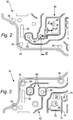
- An embodiment of the hydraulic system represented in figure 1 may for instance be a transmission block of a vehicle.
- the hydraulic system 10 comprises a first housing part 12 and a second housing part 14.
- the first housing part 12 shows a first surface 16 to be sealed which points towards the second housing part 14;
- the second housing part 14 shows a second surface 18 to be sealed which points towards the first housing part 12.
- a control plate 20 for the hydraulic system is arranged between the surfaces to be sealed, 16 and 18.
- the housing parts 12 and 14 and the control plate 20 arranged between them can be connected to each other with a connecting arrangement 22.
- This connecting arrangement 22 produces a force which braces the housing parts 12 and 14 and the control plate 20 with each other.
- the connecting arrangement 22 advantageously comprises a plurality of connecting elements 24, which are favourably screws.
- the first housing part 12 for example comprises guidances 26 for connecting elements, which are especially formed as cut-outs.
- the second housing part 14 comprises connection receptacles 28, which are especially given as inner threads.
- Typical line pressures used for the installation of the control plate are at least 8 N/mm, preferably at least 10N/mm, these line pressures allow for a sufficient sealing.
- the control plate for hydraulic systems 20 is multi-layered and comprises a first gasket layer 30, which interacts with the first surface 16 to be sealed of the first housing parts 12. On the side of the first gasket layer 30 facing away from the first surface to be sealed 16, an intermediate layer 32 is arranged.
- the control plate 20 further comprises a second gasket layer 34, which is arranged on the side of the intermediate layer 32 opposite to the first gasket layer 30, and which interacts with the second surface 18 to be sealed of the second housing part 14.
- the gasket layer 30 and 34 and the intermediate layer show through-openings 36 for fastening means which are flush and through which the connection means 24 reach.
- gasket layers 30 and 34 as well as the intermediate layer provide media trough openings which are flush and which allow a medium to pass through the control plate 20.
- the medium is preferably a fluid, in particular a transmission oil.
- Figure 2 represents a section of the first gasket layer 30; figure 3 a corresponding section of the second gasket layer 34.
- the first gasket layer 30 shows first sealing sections 40, the second gasket layer 34 second sealing sections 42.
- the sealing sections 40, 42 are embossed into the gasket layers 30, 34 and constitute beads.
- the beads are for instance formed as laterally open half-beads 44 and as laterally closed full beads 46, see also figure 4 .
- Half beads 44 are preferably used at the outer edges of the hydraulic control plate as well as around the through-openings 36 for connection elements 24; full beads allow for a large variety of designs with extensively branched bead courses.
- the half beads 44 and full beads 46 each show a solid section 48, which is distanced to the intermediate layer 32.
- a single solid section 48 via a single descending section 50 is supported on the intermediate layer 32.
- a solid material section 48 is supported via two adjacent descending sections 50, 52 being opposite to each other with respect to section 48 on the intermediate layer 32.
- the descending section 50 of a half bead 44 and the descending sections 50, 52 of a full bead 46 each merge with the contact sections 54, which rest against the intermediate layer 32.
- the coating is in most cases present at least on the surfaces of the gasket layers 30, 34 which point away from the intermediate layer 32, at least in the area of the beads 44, 46.
- the coating of the beads 44, 46 advantageously extends beyond the actual bead area, the width of the coated area preferably shows up to the five-fold, most preferably up to the three and a half-fold the width of the bead.
- other areas of the surface of a gasket layer can be coated in sections, e.g. the environment of the through-opening 36 for connecting elements 24.
- the intermediate layer 32 and the sealing layers 30 and 34 are made from a metallic material.
- the intermediate layer is for instance made from steel or aluminium or an aluminium alloy.
- the gasket layers 30 and/or 34 are for instance made from spring steel.
- the thickness 56 of the intermediate layer 32 is a multiple of the thickness of the gasket layer 30 and/or 34.
- the height of a bead 44, 45 results from the distance 60 between a contact section 54 pointing towards the intermediate layer 32 and the outer surface of a solid section 48 minus the thickness 58 of the gasket layer.
- the height of the bead is e.g. by a factor of at least about 1.5 to at the most about 3 larger than the thickness 58 of the gasket layer.
- At least one of the gasket layers may dispose of supporting elements 62 in addition to the beads 44, 46, see figure 5 .
- These supporting elements 62 are formed by structures embossed into the gasket layers 30, 34.
- the supporting elements are characterized by a supporting means' height.
- the supporting means' height results from the distance 64 of the surface of a gasket layer 30, 34 facing the intermediate layer 32 to the outer side of the supporting element 62 minus the thickness 58 of the gasket layer.
- the supporting means' height is preferably smaller than the height of the bead 44, 46. It is most preferable that the supporting means' height is less than the height of the bead.
- the supporting elements delimit the resilient oscillation distance of a full (or half) bead 46 (44). As a consequence, the minimum distance between a first surface 16 of the first housing part 12 and a surface of the contact section 54 of the first layer 30 pointing towards the intermediate layer 32 can be restricted to the supporting means' height.
- the supporting element 62 for instance shows an undulating profile with reduction of the thickness in the flanks of the profile and is preferably arranged adjacent to a through-opening 36 for fastening means.
- a supporting element 62 may for instance completely encircle a through-opening 36 for fastening means.
- the profiling with its outer contour or with single ones of its elements may follow the contour of the through-opening, thus the elements of the profiling may extend rectilinear or in a concentric manner. It is also possible that a supporting element 62 only partially surrounds a through-opening 36 for fastening means, e.g. in a half-moon shape. This allows reducing the supporting elements' demand of space.
- a cup-shaped profiling or a bead-shaped profiling meandering like a snake may be used.
- Figures 4 and 5 also demonstrate that the intermediate layer is a flat layer without any structure besides the through openings.
- control plate 20 for hydraulic systems allows for an arbitrary course of the sealing sections 40 and 42 formed by the beads 44, 46. At least a first subset 68 of the beads 44, 46 shows a circumferentially closed course, see figure 3 . This allows annularly encircling and sealing a media through-opening 38.
- a second subset 70 of the beads 44, 46 can have a circumferentially open course, see figure 3 , which allows guiding a media flow along at least one of the gasket layers 30, 34.
- the guidance of the media flow can be realized particularly well if a first bead 72 and a second bead 74 in a single gasket layer, in a top-view on the control plate, are arranged angularly with respect to each other and connected with each other in a transition area 76 (see figure 3 ). In the transition area 76, the beads 72, 74 adjoin to each other under an angle and merge with each other.
- a part of the course of the first sealing sections 40 and a part of the course of the second sealing sections 42 show no offset relative to each other, as is for instance the case for the half bead 44 arranged along the outer edge, see figure 4 . It is also possible that a part of the course of the first sealing sections 40 and at least a part of the course of the second sealing sections is arranged offset relative to each other, as is the case with the full beads 46 in the first and second gasket layer 30, 34, which are arranged in the neighbourhood to a media through opening 38, see figure 4 . It is obvious from figures 2 and 3 that these offset sections are not arranged in parallel with constant distance, but that the course of the full beads 46 in the first and second gasket layer 30, 34 is independent of each other.
- the layers 30, 32 and 34 of the control plate of the hydraulic system can be produced independent of each other, especially by punching and/or embossment.
Landscapes
- Engineering & Computer Science (AREA)
- General Engineering & Computer Science (AREA)
- Mechanical Engineering (AREA)
- Physics & Mathematics (AREA)
- Fluid Mechanics (AREA)
- Gasket Seals (AREA)
Claims (21)
- Hydrauliksystemsteuerplatte (20), umfassend eine erste Dichtungslage (30) mit ersten Dichtabschnitten (40), eine zweite Dichtungslage (34) mit zweiten Dichtabschnitten (42) und mindestens eine zwischen den Dichtungslagen (30, 34) angeordnete Zwischenlage (32), wobei die Dichtungslagen aus einem metallischen Werkstoff hergestellt sind und die Dichtabschnitte (40, 42) der Dichtungslagen (30, 24) auf der Zwischenlage (32) abgestützte in die Dichtungslagen (30, 34) eingeprägte Sicken (46) umfassen, und wobei ein Teil des Verlaufs der Sicken der ersten Dichtabschnitte (40), die für die Abdichtung einer Durchgangsöffnung (38) verwendet werden, und ein Teil des Verlaufs der entsprechenden Sicken (46) der zweiten Dichtabschnitte (42), die für die Abdichtung der Durchgangsöffnung (38) verwendet werden, relativ zueinander versetzt sind, wodurch Teile auf gegenüberliegenden Seiten der Steuerplatte (20), die unterschiedliche Geometrien aufweisen, abgedichtet werden.
- Hydrauliksystemsteuerplatte (20) nach Anspruch 1, dadurch gekennzeichnet, dass die Sicken als Vollsicken und/oder Halbsicken ausgebildet sind.
- Hydrauliksystemsteuerplatte (20) nach Anspruch 1 oder 2, dadurch gekennzeichnet, dass die mindestens eine Zwischenlage (32) einen höheren Verformungswiderstand als mindestens eine der Dichtungslagen (30,34) aufweist.
- Hydrauliksystemsteuerplatte (20) nach einem der vorhergehenden Ansprüche, dadurch gekennzeichnet, dass mindestens eine der Dichtungslagen (30, 34) aus einem elastischen Werkstoff, insbesondere aus federhartem Stahl, hergestellt ist.
- Hydrauliksystemsteuerplatte (20) nach einem der vorhergehenden Ansprüche, dadurch gekennzeichnet, dass mindestens eine der Dichtungslagen (30, 34) eine Stärke von mindestens etwa 0,1 mm und von höchstens etwa 0,5 mm aufweist.
- Hydrauliksystemsteuerplatte (20) nach einem der vorhergehenden Ansprüche, dadurch gekennzeichnet, dass die mindestens eine Zwischenlage aus einem metallischen Werkstoff hergestellt ist.
- Hydrauliksystemsteuerplatte (20) nach einem der vorhergehenden Ansprüche, dadurch gekennzeichnet, dass die mindestens eine Zwischenlage (32) eine Lagenstärke (56) von mindestens etwa 0,5 mm und höchstens etwa 5 mm, bevorzugt von mindestens etwa 0,8 mm und höchstens etwa 3 mm, aufweist.
- Hydrauliksystemsteuerplatte (20) nach einem der vorhergehenden Ansprüche, dadurch gekennzeichnet, dass das Verhältnis zwischen der Stärke (56) der mindestens einen Zwischenlage (32) und der Stärke (58) einer Dichtungslage (30, 34) mindestens etwa 2 zu 1, bevorzugt mindestens etwa 8 zu 1, beträgt.
- Hydrauliksystemsteuerplatte (20) nach einem der vorhergehenden Ansprüche, dadurch gekennzeichnet, dass das Verhältnis zwischen der Stärke (56) der mindestens einen Zwischenlage (32) und der Stärke (58) einer Dichtungslage (30, 34) höchstens etwa 40 zu 1, bevorzugt höchstens etwa 20 zu 1, beträgt.
- Hydrauliksystemsteuerplatte (20) nach einem der vorhergehenden Ansprüche, dadurch gekennzeichnet, dass ein Teil des Verlaufs der ersten Dichtabschnitte (40) und ein Teil des Verlaufs der zweiten Dichtabschnitte (42) relativ zueinander keinen Versatz aufweisen.
- Hydrauliksystemsteuerplatte (20) nach einem der vorhergehenden Ansprüche, dadurch gekennzeichnet, dass mindestens eine Teilmenge (68) der Sicken (46) einen umfangsseitig geschlossenen Verlauf aufweist.
- Hydrauliksystemsteuerplatte (20) nach einem der vorhergehenden Ansprüche, dadurch gekennzeichnet, dass mindestens eine Teilmenge (70) der Sicken (46) einen umfangsseitig offenen Verlauf aufweist.
- Hydrauliksystemsteuerplatte (20) nach einem der vorhergehenden Ansprüche, dadurch gekennzeichnet, dass mindestens eine erste Sicke (72) und mindestens eine zweite Sicke (74) einer Dichtungslage (30, 34) zueinander winklig angeordnet und in einem Übergangsbereich (76) miteinander verbunden sind.
- Hydrauliksystemsteuerplatte (20) nach einem der vorhergehenden Ansprüche, dadurch gekennzeichnet, dass mindestens eine von der Zwischenlage (32) abgewandte Oberfläche mindestens einer Dichtungslage (30, 34) zumindest teilweise mit einer Kunststoffbeschichtung versehen ist, insbesondere dass die Sicken (44, 46) auf dieser Oberfläche entlang mindestens eines Teils ihres Verlaufs mit einer Kunststoffbeschichtung versehen sind.
- Hydrauliksystemsteuerplatte (20) nach einem der vorhergehenden Ansprüche, dadurch gekennzeichnet, dass mindestens eine der Dichtungslagen (30, 34) und die mindestens eine Zwischenlage (32) lokal miteinander verbunden sind, bevorzugt durch Verschweißen und/oder formschlüssige Verbindung oder durch Vernieten.
- Hydrauliksystemsteuerplatte (20) nach einem der vorhergehenden Ansprüche, dadurch gekennzeichnet, dass sie eine Getriebeplatte eines Fahrzeugs bildet.
- Hydrauliksystemsteuerplatte (20) nach einem der vorhergehenden Ansprüche, gekennzeichnet durch mehrere Mediendurchgangsöffnungen (36), welche durch die Dichtungslagen (30, 34) und die mindestens eine Zwischenlage (32) hindurchreichen, wobei die größte der Mediendurchgangsöffnungen (36) eine maximale Erstreckung von 35 mm, bevorzugt von 30 mm, aufweist.
- Hydrauliksystemsteuerplatte (20) nach einem der vorhergehenden Ansprüche, dadurch gekennzeichnet, dass mindestens eine Mediendurchgangsöffnung (36) mit einer Durchlassregelvorrichtung, bevorzugt einem Filter oder einem Rückschlagventil, versehen ist.
- Hydrauliksystemsteuerplatte (20) nach Anspruch 18, dadurch gekennzeichnet, dass die Durchlassregelvorrichtung in der Mediendurchgangsöffnung (36) der Zwischenlage (32) fixiert ist.
- Hydrauliksystemsteuerplatte (20) nach einem der vorhergehenden Ansprüche, dadurch gekennzeichnet, dass sie derart ausgelegt ist, dass ein maximaler Dichtspalt zwischen den Dichtabschnitten (40, 42) einer Dichtungslage (30, 34) und einem mittels dieser Dichtabschnitte (40, 42) abzudichtenden Teil (12, 14) des Hydrauliksystems (10) bei einem vorbestimmten maximalen Fluiddruck maximal etwa 15 Mikrometer, bevorzugt maximal etwa 10 Mikrometer, beträgt.
- Hydrauliksystem (10) mit einer Hydrauliksystemsteuerplatte (20) nach einem der vorhergehenden Ansprüche.
Applications Claiming Priority (2)
| Application Number | Priority Date | Filing Date | Title |
|---|---|---|---|
| DE200810062829 DE102008062829B4 (de) | 2008-12-23 | 2008-12-23 | Hydrauliksystemsteuerplatte |
| PCT/EP2009/009212 WO2010072402A1 (en) | 2008-12-23 | 2009-12-22 | Hydraulic control plate |
Publications (2)
| Publication Number | Publication Date |
|---|---|
| EP2389528A1 EP2389528A1 (de) | 2011-11-30 |
| EP2389528B1 true EP2389528B1 (de) | 2018-08-29 |
Family
ID=41818750
Family Applications (1)
| Application Number | Title | Priority Date | Filing Date |
|---|---|---|---|
| EP09804011.6A Revoked EP2389528B1 (de) | 2008-12-23 | 2009-12-22 | Hydraulische steuerplatte |
Country Status (3)
| Country | Link |
|---|---|
| EP (1) | EP2389528B1 (de) |
| DE (2) | DE102008062829B4 (de) |
| WO (1) | WO2010072402A1 (de) |
Families Citing this family (23)
| Publication number | Priority date | Publication date | Assignee | Title |
|---|---|---|---|---|
| DE102009008019C5 (de) * | 2009-02-07 | 2019-02-21 | Elringklinger Ag | Getriebesteuerplatte |
| DE102010042400A1 (de) * | 2010-10-13 | 2012-04-19 | Robert Bosch Gmbh | Verfahren zum Herstellen einer hydraulischen Vorrichtung |
| DE202011103420U1 (de) | 2011-07-20 | 2012-07-23 | Reinz-Dichtungs-Gmbh | Hydrauliksystemsteuerplatte |
| DE202011103429U1 (de) * | 2011-07-20 | 2012-07-23 | Reinz-Dichtungs-Gmbh | Getriebesteuerplatte |
| DE102012202760A1 (de) * | 2012-02-23 | 2013-08-29 | Zf Friedrichshafen Ag | Hydraulisches Steuergerät für ein Getriebe |
| DE102012202759A1 (de) * | 2012-02-23 | 2013-08-29 | Zf Friedrichshafen Ag | Zwischenblechanordnung für ein hydraulisches Steuergerät |
| DE202012009539U1 (de) | 2012-10-05 | 2014-01-09 | Reinz-Dichtungs-Gmbh | Flachdichtung |
| DE102012109646A1 (de) * | 2012-10-10 | 2014-04-10 | Elringklinger Ag | Zylinderkopfdichtung |
| DE202012012058U1 (de) * | 2012-12-15 | 2013-12-16 | Reinz-Dichtungs-Gmbh | Steuereinheit |
| DE102013205220A1 (de) * | 2013-03-25 | 2014-09-25 | Elringklinger Ag | Steuerplatte |
| DE202013005264U1 (de) * | 2013-06-11 | 2014-06-12 | Reinz-Dichtungs-Gmbh | Steuerungssystem |
| DE102013219295A1 (de) | 2013-09-25 | 2015-03-26 | Elringklinger Ag | Zwischenplatte |
| DE102013219300A1 (de) | 2013-09-25 | 2015-03-26 | Elringklinger Ag | Zwischenplatte und Steuereinheit |
| DE102015102432A1 (de) * | 2015-02-20 | 2016-08-25 | Elringklinger Ag | Zwischenplatte |
| DE202015103421U1 (de) | 2015-06-29 | 2016-06-30 | Reinz-Dichtungs-Gmbh | Getriebesteuervorrichtung |
| DE202015103420U1 (de) * | 2015-06-29 | 2016-06-30 | Reinz-Dichtungs-Gmbh | Getriebesteuervorrichtung |
| DE202016101613U1 (de) * | 2016-03-23 | 2017-06-28 | Reinz-Dichtungs-Gmbh | Getriebesystemsteuerplatte und Getriebesteuersystem |
| DE202016107046U1 (de) * | 2016-12-16 | 2018-03-19 | Reinz-Dichtungs-Gmbh | Hydrauliksteuermodul |
| DE202016102266U1 (de) * | 2016-04-28 | 2017-07-31 | Reinz-Dichtungs-Gmbh | Hydrauliksystemsteuerplatte |
| DE202016106105U1 (de) | 2016-10-31 | 2018-02-01 | Reinz-Dichtungs-Gmbh | Hydrauliksystemsteuerplatte, Hydrauliksteuersystem und Getriebe |
| DE102019203238A1 (de) * | 2019-03-11 | 2020-09-17 | Zf Friedrichshafen Ag | Hydrauliksteuergerät für ein Getriebe |
| DE102020101414A1 (de) | 2020-01-22 | 2021-07-22 | Elringklinger Ag | Flachdichtung |
| DE202023102396U1 (de) * | 2023-05-03 | 2024-08-06 | Reinz-Dichtungs-Gmbh | Flachdichtung und Fluidverteilsystem |
Citations (3)
| Publication number | Priority date | Publication date | Assignee | Title |
|---|---|---|---|---|
| US3679218A (en) | 1969-03-03 | 1972-07-25 | Farnam Co F D | Unitized valve plate, gaskets and the like |
| DE19702382A1 (de) | 1996-01-31 | 1997-11-06 | Exedy Corp | Dichtungsanordnung und Trennscheibe |
| US5938208A (en) | 1994-12-30 | 1999-08-17 | Kokusan Parts Industry Co., Ltd. | Separate plate placed between adjacent valve bodies in a control valve unit of an automatic transmission |
Family Cites Families (14)
| Publication number | Priority date | Publication date | Assignee | Title |
|---|---|---|---|---|
| US5000464A (en) * | 1989-04-20 | 1991-03-19 | Ishikawa Gasket Co., Ltd. | Gasket with a fluid hole regulation device |
| US5582415A (en) * | 1993-08-31 | 1996-12-10 | Kokusan Parts Industry Co., Ltd. | Metal gasket |
| EP0773392B1 (de) | 1995-11-07 | 2004-12-15 | Nicholsons Aircraft Seals Limited | Abdichtung |
| US5680883A (en) | 1996-04-24 | 1997-10-28 | Eaton Corporation | Manifold and valve assembly and filter/gasket therefor |
| DE19641491A1 (de) * | 1996-10-09 | 1998-04-23 | Payen Goetze Gmbh | Laminierte metallische Flachdichtung |
| US6073938A (en) | 1997-11-06 | 2000-06-13 | Kokusan Parts Industry Co., Ltd. | Sealing structure |
| US6089572A (en) | 1998-03-03 | 2000-07-18 | Dana Corporation | Three-layer gasket with primary and secondary sealing element |
| DE19924260C2 (de) * | 1999-05-27 | 2003-03-20 | Reinz Dichtungs Gmbh | Metallische Flachdichtung |
| DE10018290B4 (de) * | 2000-04-13 | 2004-07-15 | Elringklinger Ag | Zylinderkopfdichtung und Verfahren zu ihrer Herstellung |
| US7059609B1 (en) * | 2000-06-13 | 2006-06-13 | Federal-Mogul World Wide, Inc. | Metal gasket with cold formed stopper |
| KR100895930B1 (ko) | 2000-06-15 | 2009-05-07 | 라인츠-디히퉁스-게엠베하 | 평개스킷 및 그 제조 방법 |
| DE10060555B4 (de) * | 2000-12-06 | 2006-11-23 | Carl Freudenberg Kg | Flachdichtung für eine Kolbenkraft- oder Arbeitsmaschine |
| DE102007019946A1 (de) * | 2007-04-27 | 2008-10-30 | Elringklinger Ag | Flachdichtung und Verfahren zur Herstellung einer Flachdichtung |
| EP1992847A1 (de) * | 2007-05-16 | 2008-11-19 | Reinz-Dichtungs-Gmbh | Metallische Flachdichtung |
-
2008
- 2008-12-23 DE DE200810062829 patent/DE102008062829B4/de not_active Revoked
-
2009
- 2009-12-22 DE DE200920018646 patent/DE202009018646U1/de not_active Expired - Lifetime
- 2009-12-22 WO PCT/EP2009/009212 patent/WO2010072402A1/en not_active Ceased
- 2009-12-22 EP EP09804011.6A patent/EP2389528B1/de not_active Revoked
Patent Citations (3)
| Publication number | Priority date | Publication date | Assignee | Title |
|---|---|---|---|---|
| US3679218A (en) | 1969-03-03 | 1972-07-25 | Farnam Co F D | Unitized valve plate, gaskets and the like |
| US5938208A (en) | 1994-12-30 | 1999-08-17 | Kokusan Parts Industry Co., Ltd. | Separate plate placed between adjacent valve bodies in a control valve unit of an automatic transmission |
| DE19702382A1 (de) | 1996-01-31 | 1997-11-06 | Exedy Corp | Dichtungsanordnung und Trennscheibe |
Non-Patent Citations (3)
| Title |
|---|
| "Auszüge aus Reparaturanleitung zu Getriebe 3 WG 161 von ZF", ZF -ERGOPOWER 3 WG-116/131/161/171 |
| JOHANSON ET AL.: "Automatic Transmissions and Transaxels", article "Excerpts from Chapters 1, 8, 9, 15", pages: 11,28,149,179,185,189 - 194,363,374-378, XP055625833 |
| WOLFGANG TIETZE: "Handbuch Dichtungspraxis", article "3 Statische Dichtungen", pages: 11 - 118.170-182, XP055625850 |
Also Published As
| Publication number | Publication date |
|---|---|
| DE102008062829B4 (de) | 2013-06-13 |
| DE202009018646U1 (de) | 2012-05-30 |
| WO2010072402A1 (en) | 2010-07-01 |
| EP2389528A1 (de) | 2011-11-30 |
| DE102008062829A1 (de) | 2010-07-01 |
Similar Documents
| Publication | Publication Date | Title |
|---|---|---|
| EP2389528B1 (de) | Hydraulische steuerplatte | |
| US6073938A (en) | Sealing structure | |
| KR101713867B1 (ko) | 편평 실 | |
| US10627002B2 (en) | Transmission control device | |
| EP2047147B1 (de) | Mehrschichtige metall-flachdichtung, insbesondere zylinderkopfdichtung | |
| US20070170659A1 (en) | Metal gasket | |
| US20090072493A1 (en) | Gasket | |
| JP2010525270A (ja) | 金属製平形ガスケット | |
| EP2188554A2 (de) | Metallzylinderkopfdichtung | |
| WO2013075891A1 (de) | Bremsscheibe | |
| US5769430A (en) | Metal gasket with bead and thermal sprayed layer thereof | |
| US20110101626A1 (en) | Flat seal | |
| EP2276950B1 (de) | Metallische flachdichtung | |
| JP2993445B2 (ja) | シール構造 | |
| CN101365902A (zh) | 用于过程控制阀的挠性密封件 | |
| EP3832175A1 (de) | Sickendichtung | |
| EP1522771B1 (de) | Metalldichtung | |
| EP2072818A1 (de) | Metallische Flachdichtung und Ihre Verwendung | |
| EP1888949B1 (de) | Dichtung | |
| EP1306588B1 (de) | Metalldichtung mit einer partiellen Oberflächenbeschichtung | |
| US20180252309A1 (en) | Transmission control device | |
| DE102018203445B4 (de) | Dichtungsanordnung, Fluidregelventil mit einer solchen Dichtungsanordnung und Verwendung eines solchen Fluidregelventils | |
| DE102004054709B4 (de) | Zylinderkopfdichtung | |
| US20060261561A1 (en) | Flat gasket, in particular cylinder-head gasket | |
| EP1740856B1 (de) | Metallflachdichtung |
Legal Events
| Date | Code | Title | Description |
|---|---|---|---|
| PUAI | Public reference made under article 153(3) epc to a published international application that has entered the european phase |
Free format text: ORIGINAL CODE: 0009012 |
|
| 17P | Request for examination filed |
Effective date: 20110513 |
|
| AK | Designated contracting states |
Kind code of ref document: A1 Designated state(s): AT BE BG CH CY CZ DE DK EE ES FI FR GB GR HR HU IE IS IT LI LT LU LV MC MK MT NL NO PL PT RO SE SI SK SM TR |
|
| DAX | Request for extension of the european patent (deleted) | ||
| 17Q | First examination report despatched |
Effective date: 20130412 |
|
| STAA | Information on the status of an ep patent application or granted ep patent |
Free format text: STATUS: EXAMINATION IS IN PROGRESS |
|
| GRAP | Despatch of communication of intention to grant a patent |
Free format text: ORIGINAL CODE: EPIDOSNIGR1 |
|
| STAA | Information on the status of an ep patent application or granted ep patent |
Free format text: STATUS: GRANT OF PATENT IS INTENDED |
|
| INTG | Intention to grant announced |
Effective date: 20180314 |
|
| GRAS | Grant fee paid |
Free format text: ORIGINAL CODE: EPIDOSNIGR3 |
|
| GRAA | (expected) grant |
Free format text: ORIGINAL CODE: 0009210 |
|
| STAA | Information on the status of an ep patent application or granted ep patent |
Free format text: STATUS: THE PATENT HAS BEEN GRANTED |
|
| AK | Designated contracting states |
Kind code of ref document: B1 Designated state(s): AT BE BG CH CY CZ DE DK EE ES FI FR GB GR HR HU IE IS IT LI LT LU LV MC MK MT NL NO PL PT RO SE SI SK SM TR |
|
| REG | Reference to a national code |
Ref country code: GB Ref legal event code: FG4D |
|
| REG | Reference to a national code |
Ref country code: CH Ref legal event code: EP |
|
| REG | Reference to a national code |
Ref country code: AT Ref legal event code: REF Ref document number: 1035506 Country of ref document: AT Kind code of ref document: T Effective date: 20180915 |
|
| REG | Reference to a national code |
Ref country code: IE Ref legal event code: FG4D |
|
| REG | Reference to a national code |
Ref country code: DE Ref legal event code: R096 Ref document number: 602009054197 Country of ref document: DE |
|
| REG | Reference to a national code |
Ref country code: NL Ref legal event code: MP Effective date: 20180829 |
|
| REG | Reference to a national code |
Ref country code: LT Ref legal event code: MG4D |
|
| PG25 | Lapsed in a contracting state [announced via postgrant information from national office to epo] |
Ref country code: FI Free format text: LAPSE BECAUSE OF FAILURE TO SUBMIT A TRANSLATION OF THE DESCRIPTION OR TO PAY THE FEE WITHIN THE PRESCRIBED TIME-LIMIT Effective date: 20180829 Ref country code: GR Free format text: LAPSE BECAUSE OF FAILURE TO SUBMIT A TRANSLATION OF THE DESCRIPTION OR TO PAY THE FEE WITHIN THE PRESCRIBED TIME-LIMIT Effective date: 20181130 Ref country code: BG Free format text: LAPSE BECAUSE OF FAILURE TO SUBMIT A TRANSLATION OF THE DESCRIPTION OR TO PAY THE FEE WITHIN THE PRESCRIBED TIME-LIMIT Effective date: 20181129 Ref country code: SE Free format text: LAPSE BECAUSE OF FAILURE TO SUBMIT A TRANSLATION OF THE DESCRIPTION OR TO PAY THE FEE WITHIN THE PRESCRIBED TIME-LIMIT Effective date: 20180829 Ref country code: NO Free format text: LAPSE BECAUSE OF FAILURE TO SUBMIT A TRANSLATION OF THE DESCRIPTION OR TO PAY THE FEE WITHIN THE PRESCRIBED TIME-LIMIT Effective date: 20181129 Ref country code: NL Free format text: LAPSE BECAUSE OF FAILURE TO SUBMIT A TRANSLATION OF THE DESCRIPTION OR TO PAY THE FEE WITHIN THE PRESCRIBED TIME-LIMIT Effective date: 20180829 Ref country code: LT Free format text: LAPSE BECAUSE OF FAILURE TO SUBMIT A TRANSLATION OF THE DESCRIPTION OR TO PAY THE FEE WITHIN THE PRESCRIBED TIME-LIMIT Effective date: 20180829 Ref country code: IS Free format text: LAPSE BECAUSE OF FAILURE TO SUBMIT A TRANSLATION OF THE DESCRIPTION OR TO PAY THE FEE WITHIN THE PRESCRIBED TIME-LIMIT Effective date: 20181229 |
|
| REG | Reference to a national code |
Ref country code: AT Ref legal event code: MK05 Ref document number: 1035506 Country of ref document: AT Kind code of ref document: T Effective date: 20180829 |
|
| PG25 | Lapsed in a contracting state [announced via postgrant information from national office to epo] |
Ref country code: HR Free format text: LAPSE BECAUSE OF FAILURE TO SUBMIT A TRANSLATION OF THE DESCRIPTION OR TO PAY THE FEE WITHIN THE PRESCRIBED TIME-LIMIT Effective date: 20180829 Ref country code: ES Free format text: LAPSE BECAUSE OF FAILURE TO SUBMIT A TRANSLATION OF THE DESCRIPTION OR TO PAY THE FEE WITHIN THE PRESCRIBED TIME-LIMIT Effective date: 20180829 Ref country code: LV Free format text: LAPSE BECAUSE OF FAILURE TO SUBMIT A TRANSLATION OF THE DESCRIPTION OR TO PAY THE FEE WITHIN THE PRESCRIBED TIME-LIMIT Effective date: 20180829 |
|
| REG | Reference to a national code |
Ref country code: DE Ref legal event code: R026 Ref document number: 602009054197 Country of ref document: DE |
|
| PLBI | Opposition filed |
Free format text: ORIGINAL CODE: 0009260 |
|
| PG25 | Lapsed in a contracting state [announced via postgrant information from national office to epo] |
Ref country code: EE Free format text: LAPSE BECAUSE OF FAILURE TO SUBMIT A TRANSLATION OF THE DESCRIPTION OR TO PAY THE FEE WITHIN THE PRESCRIBED TIME-LIMIT Effective date: 20180829 Ref country code: CZ Free format text: LAPSE BECAUSE OF FAILURE TO SUBMIT A TRANSLATION OF THE DESCRIPTION OR TO PAY THE FEE WITHIN THE PRESCRIBED TIME-LIMIT Effective date: 20180829 Ref country code: RO Free format text: LAPSE BECAUSE OF FAILURE TO SUBMIT A TRANSLATION OF THE DESCRIPTION OR TO PAY THE FEE WITHIN THE PRESCRIBED TIME-LIMIT Effective date: 20180829 Ref country code: AT Free format text: LAPSE BECAUSE OF FAILURE TO SUBMIT A TRANSLATION OF THE DESCRIPTION OR TO PAY THE FEE WITHIN THE PRESCRIBED TIME-LIMIT Effective date: 20180829 Ref country code: IT Free format text: LAPSE BECAUSE OF FAILURE TO SUBMIT A TRANSLATION OF THE DESCRIPTION OR TO PAY THE FEE WITHIN THE PRESCRIBED TIME-LIMIT Effective date: 20180829 Ref country code: PL Free format text: LAPSE BECAUSE OF FAILURE TO SUBMIT A TRANSLATION OF THE DESCRIPTION OR TO PAY THE FEE WITHIN THE PRESCRIBED TIME-LIMIT Effective date: 20180829 |
|
| 26 | Opposition filed |
Opponent name: ELRINGKLINGER AG Effective date: 20190410 |
|
| PG25 | Lapsed in a contracting state [announced via postgrant information from national office to epo] |
Ref country code: DK Free format text: LAPSE BECAUSE OF FAILURE TO SUBMIT A TRANSLATION OF THE DESCRIPTION OR TO PAY THE FEE WITHIN THE PRESCRIBED TIME-LIMIT Effective date: 20180829 Ref country code: SK Free format text: LAPSE BECAUSE OF FAILURE TO SUBMIT A TRANSLATION OF THE DESCRIPTION OR TO PAY THE FEE WITHIN THE PRESCRIBED TIME-LIMIT Effective date: 20180829 Ref country code: SM Free format text: LAPSE BECAUSE OF FAILURE TO SUBMIT A TRANSLATION OF THE DESCRIPTION OR TO PAY THE FEE WITHIN THE PRESCRIBED TIME-LIMIT Effective date: 20180829 |
|
| PLAX | Notice of opposition and request to file observation + time limit sent |
Free format text: ORIGINAL CODE: EPIDOSNOBS2 |
|
| REG | Reference to a national code |
Ref country code: CH Ref legal event code: PL |
|
| GBPC | Gb: european patent ceased through non-payment of renewal fee |
Effective date: 20181222 |
|
| PG25 | Lapsed in a contracting state [announced via postgrant information from national office to epo] |
Ref country code: SI Free format text: LAPSE BECAUSE OF FAILURE TO SUBMIT A TRANSLATION OF THE DESCRIPTION OR TO PAY THE FEE WITHIN THE PRESCRIBED TIME-LIMIT Effective date: 20180829 Ref country code: LU Free format text: LAPSE BECAUSE OF NON-PAYMENT OF DUE FEES Effective date: 20181222 Ref country code: MC Free format text: LAPSE BECAUSE OF FAILURE TO SUBMIT A TRANSLATION OF THE DESCRIPTION OR TO PAY THE FEE WITHIN THE PRESCRIBED TIME-LIMIT Effective date: 20180829 |
|
| REG | Reference to a national code |
Ref country code: IE Ref legal event code: MM4A |
|
| REG | Reference to a national code |
Ref country code: BE Ref legal event code: MM Effective date: 20181231 |
|
| PLBB | Reply of patent proprietor to notice(s) of opposition received |
Free format text: ORIGINAL CODE: EPIDOSNOBS3 |
|
| PG25 | Lapsed in a contracting state [announced via postgrant information from national office to epo] |
Ref country code: IE Free format text: LAPSE BECAUSE OF NON-PAYMENT OF DUE FEES Effective date: 20181222 |
|
| PG25 | Lapsed in a contracting state [announced via postgrant information from national office to epo] |
Ref country code: BE Free format text: LAPSE BECAUSE OF NON-PAYMENT OF DUE FEES Effective date: 20181231 |
|
| PG25 | Lapsed in a contracting state [announced via postgrant information from national office to epo] |
Ref country code: CH Free format text: LAPSE BECAUSE OF NON-PAYMENT OF DUE FEES Effective date: 20181231 Ref country code: GB Free format text: LAPSE BECAUSE OF NON-PAYMENT OF DUE FEES Effective date: 20181222 Ref country code: LI Free format text: LAPSE BECAUSE OF NON-PAYMENT OF DUE FEES Effective date: 20181231 |
|
| PG25 | Lapsed in a contracting state [announced via postgrant information from national office to epo] |
Ref country code: MT Free format text: LAPSE BECAUSE OF NON-PAYMENT OF DUE FEES Effective date: 20181222 |
|
| PGFP | Annual fee paid to national office [announced via postgrant information from national office to epo] |
Ref country code: FR Payment date: 20191226 Year of fee payment: 11 |
|
| PG25 | Lapsed in a contracting state [announced via postgrant information from national office to epo] |
Ref country code: TR Free format text: LAPSE BECAUSE OF FAILURE TO SUBMIT A TRANSLATION OF THE DESCRIPTION OR TO PAY THE FEE WITHIN THE PRESCRIBED TIME-LIMIT Effective date: 20180829 |
|
| PG25 | Lapsed in a contracting state [announced via postgrant information from national office to epo] |
Ref country code: PT Free format text: LAPSE BECAUSE OF FAILURE TO SUBMIT A TRANSLATION OF THE DESCRIPTION OR TO PAY THE FEE WITHIN THE PRESCRIBED TIME-LIMIT Effective date: 20180829 |
|
| PG25 | Lapsed in a contracting state [announced via postgrant information from national office to epo] |
Ref country code: HU Free format text: LAPSE BECAUSE OF FAILURE TO SUBMIT A TRANSLATION OF THE DESCRIPTION OR TO PAY THE FEE WITHIN THE PRESCRIBED TIME-LIMIT; INVALID AB INITIO Effective date: 20091222 Ref country code: MK Free format text: LAPSE BECAUSE OF NON-PAYMENT OF DUE FEES Effective date: 20180829 Ref country code: CY Free format text: LAPSE BECAUSE OF FAILURE TO SUBMIT A TRANSLATION OF THE DESCRIPTION OR TO PAY THE FEE WITHIN THE PRESCRIBED TIME-LIMIT Effective date: 20180829 |
|
| PG25 | Lapsed in a contracting state [announced via postgrant information from national office to epo] |
Ref country code: FR Free format text: LAPSE BECAUSE OF NON-PAYMENT OF DUE FEES Effective date: 20201231 |
|
| APBM | Appeal reference recorded |
Free format text: ORIGINAL CODE: EPIDOSNREFNO |
|
| APBP | Date of receipt of notice of appeal recorded |
Free format text: ORIGINAL CODE: EPIDOSNNOA2O |
|
| APAH | Appeal reference modified |
Free format text: ORIGINAL CODE: EPIDOSCREFNO |
|
| APBM | Appeal reference recorded |
Free format text: ORIGINAL CODE: EPIDOSNREFNO |
|
| APBP | Date of receipt of notice of appeal recorded |
Free format text: ORIGINAL CODE: EPIDOSNNOA2O |
|
| APBQ | Date of receipt of statement of grounds of appeal recorded |
Free format text: ORIGINAL CODE: EPIDOSNNOA3O |
|
| P01 | Opt-out of the competence of the unified patent court (upc) registered |
Effective date: 20230522 |
|
| PGFP | Annual fee paid to national office [announced via postgrant information from national office to epo] |
Ref country code: DE Payment date: 20231121 Year of fee payment: 15 |
|
| REG | Reference to a national code |
Ref country code: DE Ref legal event code: R103 Ref document number: 602009054197 Country of ref document: DE Ref country code: DE Ref legal event code: R064 Ref document number: 602009054197 Country of ref document: DE |
|
| APBU | Appeal procedure closed |
Free format text: ORIGINAL CODE: EPIDOSNNOA9O |
|
| RDAF | Communication despatched that patent is revoked |
Free format text: ORIGINAL CODE: EPIDOSNREV1 |
|
| STAA | Information on the status of an ep patent application or granted ep patent |
Free format text: STATUS: PATENT REVOKED |
|
| RDAG | Patent revoked |
Free format text: ORIGINAL CODE: 0009271 |
|
| REG | Reference to a national code |
Ref country code: CH Ref legal event code: PL |
|
| 27W | Patent revoked |
Effective date: 20240910 |